BRITISH COLUMBIA SAFETY AUTHORITY www.safetyauthority.ca Incident Summary (5603257) SUPPORTING INFORMATION Incident Date August 4, 2016 Location Victoria Regulated industry sector Zip line Impact Injury Qty injuries 2 Injury description One person sustained a broken wrist and back injury and a second person sustained a concussion. Injury rating Moderate Damage Damage description Failure of zip line anchor bolt. Damaged zip line cable. Damage rating Major Incident rating Major Incident overview It was reported to BCSA that a zip line tension anchor bolt failed. The failure caused the complete release of the zip line cable. One person was riding the zip line at the time of the failure, the release of the cable caused this person to fall to the ground several meters. A second person was holding on to the zip line cable at the loading area deck of the zip line when the failure occurred causing them to be thrown several meters off of the loading area deck to the ground. INVESTIGATION CONCLUSIONS Site, system and components This is a recreational zip line in a forested area. The zip line is 133 meters in length, installed in 2007. A zip line has a steel cable stretched between two anchors. The cable is tensioned to provide sufficient support for passengers. Zip line steel cables and anchor points are designed to withstand the tension forces applied and the most adverse loading conditions. The upper end of the zip line cable was anchored to a 1” steel eyebolt. The eyebolt was connected to a rod embedded in concrete by means of a threaded connecting nut. Passengers ride the tensioned cable by means of a trolley assembly attached to a body harness. The passenger’s trolley is attached to the cable at a loading platform (upper cable anchor point area). The passengers ride the cable to a unloading platform ( lower cable anchor point area). The passengers are slowed down by a braking system at the unloading platform and assisted by a trained guide to remove the passenger trolley from the zip line cable. Failure scenario(s) The design of the anchor did not specify the orientation or material standards of the eyebolt anchor. The eyebolt anchor was installed in an orientation that resulted with a relatively large bending moment applied to the threads of the eyebolt. The eyebolt material was both weaker and less tolerant to damage than others typically used in this application of similar size. There was insufficient margin between the loads applied to the eyebolt and the material strength of the eyebolt. Over time, fatigue cracking developed at the thread root at the point of maximum stress. With continued use, the crack propagated into the material until a rapid and complete brittle failure occurred. Facts and evidence Eyebolt Material and Fracture Analysis - There was no material or manufacturer identification on the eyebolt. - There was no hardened surface layer. Surface hardening is used to improve resistance to high stress, fatigue and surface damage.
Transcript
BRITISH COLUMBIA SAFETY AUTHORITY www.safetyauthority.ca
Incident Summary (5603257)
SUP
PO
RTI
NG
INFO
RM
ATI
ON
Incident Date August 4, 2016
Location Victoria
Regulated industry sector Zip line
Imp
act In
jury
Qty injuries 2
Injury description
One person sustained a broken wrist and back injury and a second person sustained a concussion.
Injury rating Moderate
Dam
age
Damage description
Failure of zip line anchor bolt. Damaged zip line cable.
Damage rating Major
Incident rating Major
Incident overview
It was reported to BCSA that a zip line tension anchor bolt failed. The failure caused the complete release of the zip line cable. One person was riding the zip line at the time of the failure, the release of the cable caused this person to fall to the ground several meters. A second person was holding on to the zip line cable at the loading area deck of the zip line when the failure occurred causing them to be thrown several meters off of the loading area deck to the ground.
INV
ESTI
GA
TIO
N C
ON
CLU
SIO
NS
Site, system and components
This is a recreational zip line in a forested area. The zip line is 133 meters in length, installed in 2007. A zip line has a steel cable stretched between two anchors. The cable is tensioned to provide sufficient support for passengers. Zip line steel cables and anchor points are designed to withstand the tension forces applied and the most adverse loading conditions. The upper end of the zip line cable was anchored to a 1” steel eyebolt. The eyebolt was connected to a rod embedded in concrete by means of a threaded connecting nut. Passengers ride the tensioned cable by means of a trolley assembly attached to a body harness. The passenger’s trolley is attached to the cable at a loading platform (upper cable anchor point area). The passengers ride the cable to a unloading platform ( lower cable anchor point area). The passengers are slowed down by a braking system at the unloading platform and assisted by a trained guide to remove the passenger trolley from the zip line cable.
Failure scenario(s)
The design of the anchor did not specify the orientation or material standards of the eyebolt anchor. The eyebolt anchor was installed in an orientation that resulted with a relatively large bending moment applied to the threads of the eyebolt. The eyebolt material was both weaker and less tolerant to damage than others typically used in this application of similar size. There was insufficient margin between the loads applied to the eyebolt and the material strength of the eyebolt. Over time, fatigue cracking developed at the thread root at the point of maximum stress. With continued use, the crack propagated into the material until a rapid and complete brittle failure occurred.
Facts and evidence
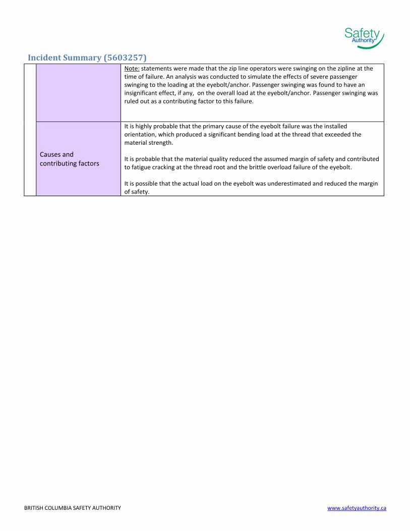
Eyebolt Material and Fracture Analysis - There was no material or manufacturer identification on the eyebolt. - There was no hardened surface layer. Surface hardening is used to improve resistance to high stress, fatigue and surface damage.
BRITISH COLUMBIA SAFETY AUTHORITY www.safetyauthority.ca
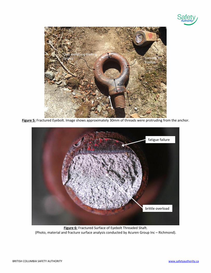
Incident Summary (5603257) -The strength of the eyebolt, estimated from hardness testing, was 20% lower than typical for similar as-rolled or annealed grade steel. -The low ductility (ability to deform) appearance of the failure area of eyebolt indicates heat treatment practices were inadequate to maintain the typical ductility for this grade of steel. Ductility of material allows for ‘slow’ failures that may be detected by inspection prior to complete failure. - A deflection of approximately 3 degrees was measured in the loading plane of the eyebolt. This deflection reflects the amount of material deformation prior to failure. -Cracks were present in several anchor bolt thread roots near the fracture, and corrosion was present in most bolt thread roots. -The cracks were straight and roughly horizontal, and filled with corrosion deposits, indicating fatigue cracks that were present for some time. -23 % of the bolt diameter was corroded and dark-coloured, indicating that a crack was present to that point for at least several weeks, likely months. The flat smooth surface and straight lines across this region are typical of progressive crack growth due to fatigue. The remainder of the fracture face was shiny and crystalline, indicating brittle fracture. -Cracking in several threads adjacent to the failure indicated the service the eyebolt was in exceeded its fatigue strength. Zip Line Design - Load on the anchor was defined as 7.8KN (3/8 cable per original design) - Cable increased from 3/8” to 1/2" in 2009
- Drawing note defines anchor and eyebolt as follows: 25∅[1” diameter] THREADED ROD
EMBEDDED 1000 INTO ROCK WITH APPROVED GROUT. THREAD ON 25∅[1” diameter] GALV.
FORGED EYE NUT - Original designer stated that loading was assumed to be in line with the eyebolt threaded shaft/embedded rod - Original design calculations support a safety factor of 5 between the defined load of 7.8KN and an in line eyebolt capacity of 44.5KN (typical in line published working load for 1 inch eyebolts) Eyebolt Installed Configuration - eyebolt was loaded at an angle of 47.1 degrees - eyebolt shoulder was not threaded and seated flush onto anchor surface - eyebolt was loaded such that the direction of pull was 11 degrees from the plane of the eyebolt Zip Line Engineering Analysis of Eyebolt/Anchor Orientation - a model of the zip line was created and estimated the loads at the eyebolt/anchor could have been 33.4KN (1/2” cable only) and 43.4KN (including person + wind). - analysis considering the
- angular loading at 47.1 degrees - material strength reduction of 20%
concluded that the eyebolt was overstressed in this orientation.
BRITISH COLUMBIA SAFETY AUTHORITY www.safetyauthority.ca
Incident Summary (5603257) Note: statements were made that the zip line operators were swinging on the zipline at the time of failure. An analysis was conducted to simulate the effects of severe passenger swinging to the loading at the eyebolt/anchor. Passenger swinging was found to have an insignificant effect, if any, on the overall load at the eyebolt/anchor. Passenger swinging was ruled out as a contributing factor to this failure.
Causes and contributing factors
It is highly probable that the primary cause of the eyebolt failure was the installed orientation, which produced a significant bending load at the thread that exceeded the material strength. It is probable that the material quality reduced the assumed margin of safety and contributed to fatigue cracking at the thread root and the brittle overload failure of the eyebolt. It is possible that the actual load on the eyebolt was underestimated and reduced the margin of safety.