45
Incompressible Potential Flow Panel Methods (3)
Incompressible Potential FlowPanel Methods (3)

Outline• Some Potential Theory• Derivation of the Integral Equation for the Potential• Classic Panel Method• Program PANEL• Subsonic Airfoil Aerodynamics• Issues in the Problem formulation for 3D flow over aircraft• Example applications of panel methods• Using Panel Methods• Advanced panel methods

Program PANEL• Description of PANEL
– An exact implementation of the classic method (2D)
– Including a subroutine to generate the ordinates for the NACA 4-digit and 5-digit airfoils
– The main drawback is the requirement for a trailing edge thickness that’s exactly zero.
– The node points are distributed employing the widely used cosine spacing function.

• Study on the convergence– Sensitivity of the solution (Cd, Cl, Cm) to
the number of panels
Change of drag with number of panels

Change of lift with number of panels

Change of pitching moment with the inverse of the number of panels
Conclusion:Results are relatively insensitive to the number of panels once fifty or sixty panels are used.

• Study on the convergence– Sensitivity of the the pressure to the number
of panels
Pressure distribution from program PANEL, 20 Panels
More panels are required to define the details of the pressure distribution.
The stagnation pressure region on the lower surface of the leading edge is not yet distinct.
The expansion peak and trailing edge recovery pressure are not resolved clearly.
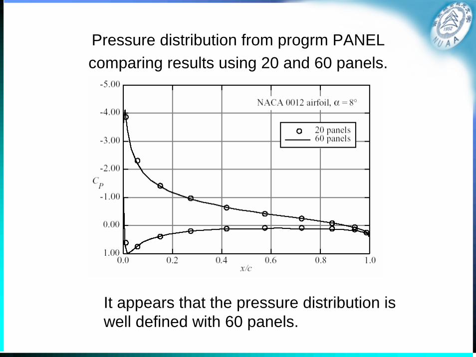
Pressure distribution from progrm PANELcomparing results using 20 and 60 panels.
It appears that the pressure distribution is well defined with 60 panels.
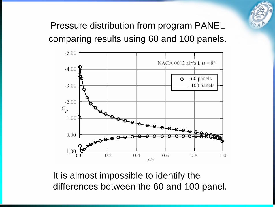
Pressure distribution from program PANELcomparing results using 60 and 100 panels.
It is almost impossible to identify the differences between the 60 and 100 panel.

• Validation– Comparison of results with an exact solution
Comparison of results from PANEL with an essentially exact mapping solution for the NACA 4412 airfoil at 6° angle-of-attack.
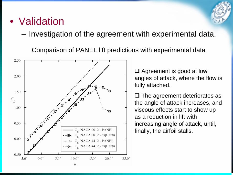
• Validation– Investigation of the agreement with experimental data.
Comparison of PANEL lift predictions with experimental data
Agreement is good at low angles of attack, where the flow is fully attached.
The agreement deteriorates as the angle of attack increases, and viscous effects start to show up as a reduction in lift with increasing angle of attack, until, finally, the airfoil stalls.

Comparison of PANEL moment predictions with experimental data
The computed location of the aerodynamic center, dCm / dCL = 0 , is not exactly at the quarter chord, although the experimental data is very close to this value.
The uncambered NACA 0012 data shows nearly zero pitching moment until flow separation starts to occur.
The cambered airfoil shows a significant pitching moment, and a trend due to viscous effects that is exactly opposite the computed prediction.

Comparison of pressure distribution from PANEL with data
In general the agreement is very good.
The primary area of disagreement is at the trailing edge. Here viscous effects act to prevent the recovery of the experimental pressure to the levels predicted by the inviscid solution.
2
211
2
pp p vC
vvρ∞
∞∞
⎛ ⎞−= = − ⎜ ⎟
⎝ ⎠
• Limitation – Panel methods often have trouble with
accuracy at the trailing edge of airfoils with cusped trailing edges, so that the included angle at the trailing edge is zero.

PANEL Performance near the airfoil trailing edge
Comparison at the trailing edge of 6- and 6A-series airfoil geometries
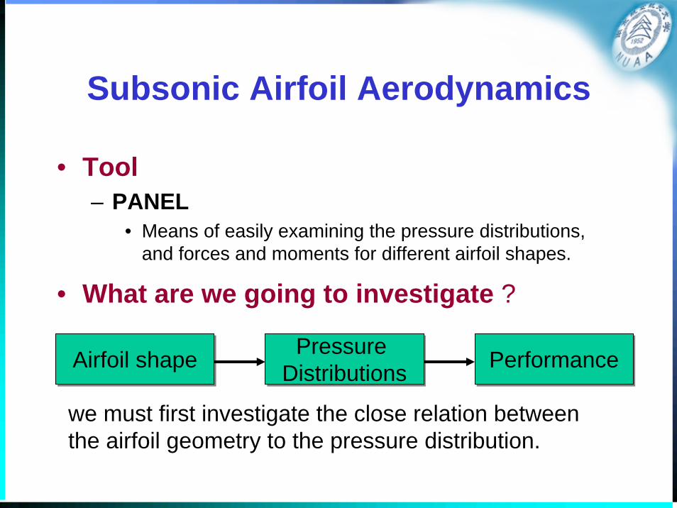
Subsonic Airfoil Aerodynamics
• Tool– PANEL
• Means of easily examining the pressure distributions, and forces and moments for different airfoil shapes.
• What are we going to investigate ?
Airfoil shapeAirfoil shape Pressure DistributionsPressure
Distributions PerformancePerformance
we must first investigate the close relation between the airfoil geometry to the pressure distribution.
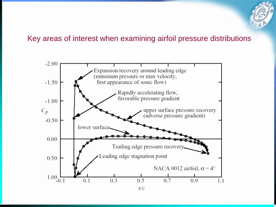
Key areas of interest when examining airfoil pressure distributions

Airfoil Pressures and Performance

• Overview of Airfoil Characteristics– Drag
– Lift• The slop of the lift curve
– Thin airfoil theory predicts that the lift curve slope should be 2π
– Thick airfoil theory says that it should be slightly greater than 2π, with 2π being the limit for zero thickness.
• Zero-lift angle
– Moment• Thin airfoil theory predicts that subsonic airfoils have their
aerodynamic centers at the quarter chord for attached flow.
• The value of Cm0 depends on the camber

• Investigation of Airfoil Pressure Distributions– Uncambered airfoils
The a = 0° case produces a mild expansion around the leading edge followed by a monotonic recovery to the trailing edge pressure.
As the angle of attack increases the pressure begins to expand rapidly around the leading edge, reaching a very low pressure, and resulting in an increasingly steep pressure recovery at the leading edge.
Effect of angle of attack on the pressure distribution

Comparison of NACA 4-digit airfoils of 6, 12, and 18% thicknesses

Effect of airfoil thickness on the pressure distribution at zero lift
The thicker airfoil produces a larger disturbance, and lower minimum pressure.

Effect of airfoil thickness on the pressure distribution at CL = 0.48
The thinnest airfoil shows a dramatic expansion and recompression.
The thicker airfoil results in a significantly milder expansion and subsequent recompression.

• Investigation of Airfoil Pressure Distributions– Cambered airfoils
Comparison of uncambered and cambered NACA 4-digit airfoils
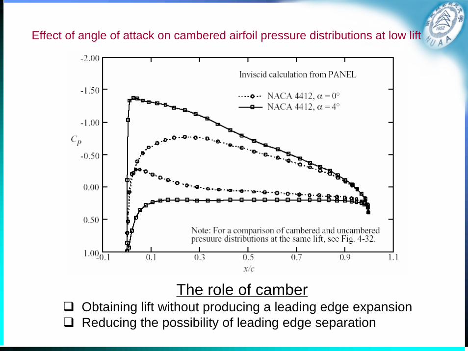
Effect of angle of attack on cambered airfoil pressure distributions at low lift
The role of camberObtaining lift without producing a leading edge expansionReducing the possibility of leading edge separation

Camber effects on airfoil pressure distributionsat CL = 0.48

Camber effects on airfoil pressure distributionsat CL = 0.96
Distribution is very different !
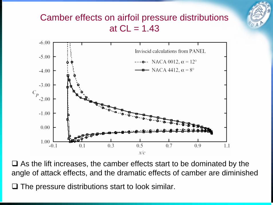
Camber effects on airfoil pressure distributions at CL = 1.43
As the lift increases, the camber effects start to be dominated by the angle of attack effects, and the dramatic effects of camber are diminished
The pressure distributions start to look similar.

The effect of extreme aft camber

Comments on airfoil with extreme aft camber
• This is part of the design strategy of Whitcomb when the so-called NASA supercritical airfoils were developed.
• The aft camber “opens up” the pressure distribution near the trailing edge.
• Two adverse properties– the large zero lift pitching moment
– the delayed and then rapid pressure recovery on the upper surface
• This type of pressure recovery is a very poor way to try to achieve a significant pressure recovery because the boundary layer will separate early.

An advanced airfoil: GA(W)-1 airfoil
• 17% thick airfoil• Providing better maximum lift and stall
characteristics

Pressure distribution at zero angle of attack of the GA(W)-1
• The upper surface pressure distribution reaches a constant pressure plateau, and then has a moderate pressure recovery.
• Aft camber is used to obtain lift on the lower surface and “open up” the airfoil pressure distribution near the trailing edge.

Geometry and Design• Effects of Shape Changes on Pressure
Distributions– Shape changes
• camber and thickness.
• local modifications to the airfoil surface
• small deflections of the trailing edge
• Shape for a specified pressure distribution– The inverse problem
• The aerodynamic designer wants to find the geometric shape corresponding to a prescribed pressure distribution from scratch.

Airfoil analysis and design
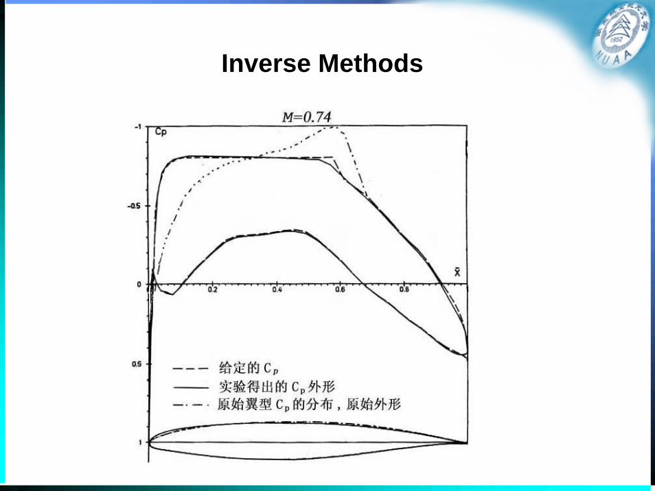
Inverse Methods
Introduction to PABLO
Potential flow around Airfoils with Boundary Layer coupled One-way
KTH- The Royal Institute of Technology Department of Aeronautics
Stockholm, Sweden Programmed by Christian Wauquiez, 1999

Program PABLO description• A pedagogical low-speed airfoil analysis program written in MATLAB
• Using one way coupled inviscid + boundary layer model
• The inviscid flow is solved using a Panel Method. Three different kinds of singularity distributions can be used.
– Constant-strength sources
– Constant-strength doublets
– Linear vortices
• Three different kinds of geometries are implemented
– Ellipse with prescribed axis ratio
– NACA 4 digits airfoil library
– General airfoil library

Program PABLO description
• The boundary layer equations– Thwaites' equations for the laminar part of the flow
– Head's equations for the turbulent part
– Michel's criterion is used to locate transition
– The drag coefficient is computed using the Squire-Young formula
• The solution computed by the program– The Cp distribution
– The aerodynamics coefficients CL, CD and CM
– The coordinate of the center of pressure Xcp
– The location of transition and eventual laminar or turbulent separation
– The distribution of the boundary layer parameters
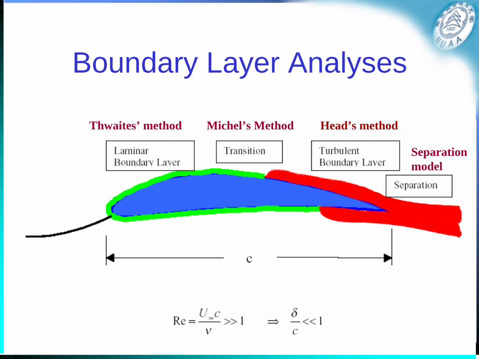
Boundary Layer Analyses
Head’s methodMichel’s MethodThwaites’ method
Separation model

PABLO
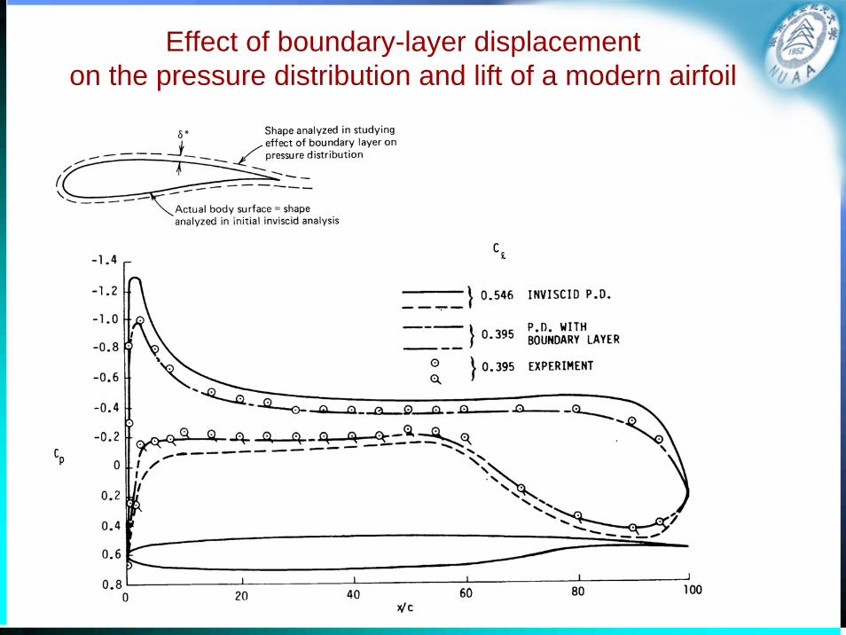
Effect of boundary-layer displacement on the pressure distribution and lift of a modern airfoil

Coupled inviscid / viscous iterative methods

Introduction to XFOIL
• XFOIL is a software which goal was to combine the speed and accuracy of high-order panel methods with the new fully-coupled viscous/inviscid interaction methods.
• It was developed by Dr. Mark Drela, MIT and Harold Youngren, Aerocraft, Inc.
• It consists of a collection of menu-driven routines which perform various useful functions.– “Profili” based on Xfoil has a nice interface

Introduction to XFOIL
• Functions– Viscous (or inviscid) analysis of an existing airfoil
– Airfoil design and redesign by interactive specification of a surface speed distribution via screen cursor or mouse.
– Airfoil redesign by interactive specification of new geometric parameters
– Blending of airfoils
– Drag polar calculation with fixed or varying Reynolds and/or Mach numbers.
– Writing and reading of airfoil geometry and polar save files
– Plotting of geometry, pressure distributions, and polar.
Homework 3• Study on the convergence using PABLO/XFoil
– Sensitivity of the solution (Cl, Cm) to the number of panels
• Validation on PABLO/Xfoil– Compare Cl, Cm from PABLO/Xfoil with the experiment data
• Study on the airfoil aerodynamics– Camber effects on airfoil pressure distributions at same angle of
attack
– Camber effects on airfoil pressure distributions at same lift coefficient
– Camber effects on the angle of attack at which lift is zero


