1 INCORRECT VALVE SELECTION ON PLUNGER PUMPS RESULTS IN UNDETECTED HIGH FREQUENCY VIBRATION AND COSTLY FAILURES, A CASE STUDY Brian C. Howes, M.Sc., P.Eng. Lyle Berg, B.Sc Val Zacharias, M.A. Beta Machinery Analysis Ltd. Suite 300, 1615 Tenth Avenue Southwest Calgary, AB, T3C 0J7 For Canadian Machinery Vibration Association 1996 Annual Meeting ABSTRACT An amine triplex plunger pump system had been extremely noisy during the four months since its installation. Piping welds and nipples on the discharge piping had failed frequently, causing substantial loss of amine each time. The owner installed discharge pulsation dampers on the triplex pump. This procedure eliminated a severe vibration, but failures of nipples persisted on the discharge piping. Spectrum analysis and normal piping vibration guidelines did not indicate that the vibration was severe enough to cause such problems. The vibration waveform, however, showed positive and negative 1.0 in/s spikes at irregular intervals. The suction valve closing angles were up to 30 degrees after dead centre and the discharge valve closing angles were up to 23 degrees after dead centre. On the recommendation of Beta and with the concurrence of the pump supplier, the owner installed valves with stiffer springs to correct the late valve closures. The original suction and discharge valve sleeves were found to have excessive wear. Some of the valve plates and backguards were also worn. Cavitation damage was found on at least one plunger. When the pump was run with the new valves it was so quiet that operators questioned whether the pump was functioning. The suction and discharge valve closing angles were around 10 degrees after dead centre. The time base plot of the vibration waveform showed the vibration levels to be significantly lower, and the large positive and negative spikes were no longer occurring. 1. THE PROBLEM An amine triplex plunger pump system had been extremely noisy during the four months since its installation. Piping welds and nipples on the discharge piping had failed frequently, causing substantial loss of amine and plant downtime each time. The owner then sought third party assistance. 2. THE SYSTEM The amine system consists of two triplex plunger pumps, with one at 100% standby, as shown in Figure 1. The system is used to remove hydrogen sulfide and carbon dioxide from a natural gas stream. Each plunger pump had six valves, with steel plates. Motor speed was about 1760 RPM and the pumps were belt driven to run at approximately 337 RPM. The suction side had a booster pump and a desurger, and the discharge side had a desurger. http://www.BetaMachinery.com
Transcript
1
INCORRECT VALVE SELECTION ON PLUNGER PUMPS RESULTS IN
UNDETECTED HIGH FREQUENCY VIBRATION AND COSTLY FAILURES,
A CASE STUDY
Brian C. Howes, M.Sc., P.Eng. Lyle Berg, B.Sc Val Zacharias, M.A.
For Canadian Machinery Vibration Association 1996 Annual Meeting
ABSTRACTAn amine triplex plunger pump system had beenextremely noisy during the four months since itsinstallation. Piping welds and nipples on thedischarge piping had failed frequently, causingsubstantial loss of amine each time. The ownerinstalled discharge pulsation dampers on thetriplex pump. This procedure eliminated asevere vibration, but failures of nipples persistedon the discharge piping.
Spectrum analysis and normal piping vibrationguidelines did not indicate that the vibration wassevere enough to cause such problems. Thevibration waveform, however, showed positiveand negative 1.0 in/s spikes at irregularintervals. The suction valve closing angles wereup to 30 degrees after dead centre and thedischarge valve closing angles were up to 23degrees after dead centre.
On the recommendation of Beta and with theconcurrence of the pump supplier, the ownerinstalled valves with stiffer springs to correct thelate valve closures. The original suction anddischarge valve sleeves were found to haveexcessive wear. Some of the valve plates andbackguards were also worn. Cavitation damagewas found on at least one plunger.
When the pump was run with the new valves itwas so quiet that operators questioned whetherthe pump was functioning. The suction anddischarge valve closing angles were around 10degrees after dead centre. The time base plot
of the vibration waveform showed the vibrationlevels to be significantly lower, and the largepositive and negative spikes were no longeroccurring.
1. THE PROBLEM
An amine triplex plunger pump system had beenextremely noisy during the four months since itsinstallation. Piping welds and nipples on thedischarge piping had failed frequently, causingsubstantial loss of amine and plant downtimeeach time.
The owner then sought third party assistance.
2. THE SYSTEM
The amine system consists of two triplex plungerpumps, with one at 100% standby, as shown inFigure 1. The system is used to removehydrogen sulfide and carbon dioxide from anatural gas stream. Each plunger pump had sixvalves, with steel plates.
Motor speed was about 1760 RPM and thepumps were belt driven to run at approximately337 RPM.
The suction side had a booster pump and adesurger, and the discharge side had adesurger.
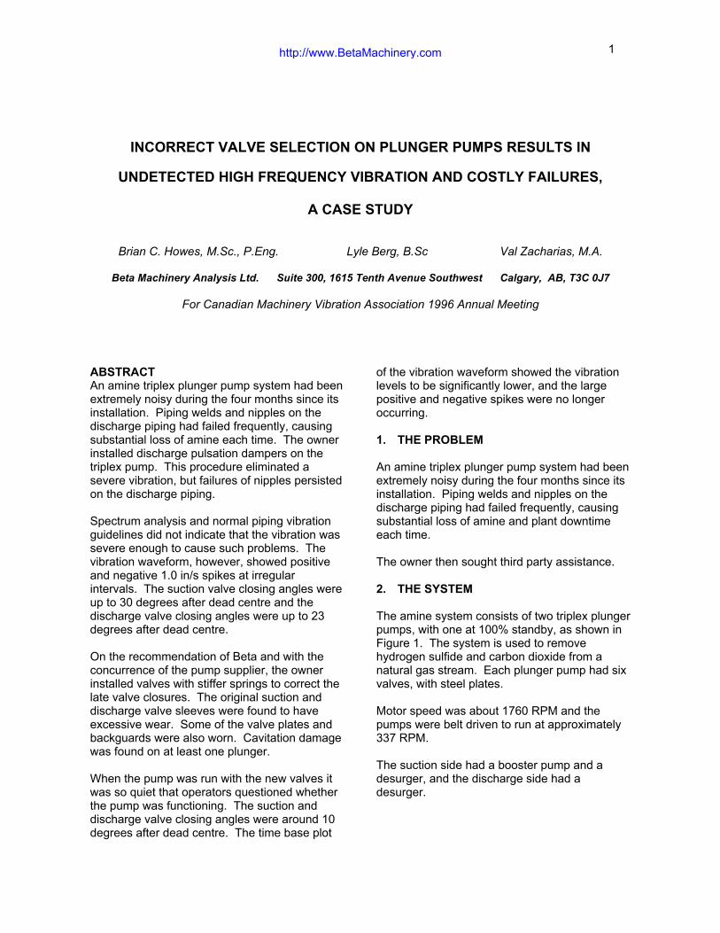
Figure 1 Two identical plunger pumps, with one on 100% standby, are used to remove hydrogensulfide and carbon dioxide from a natural gas stream. Both pumps experienced failures onthe discharge piping.
3. THE HISTORY
Figure 1 shows the areas where failuresoccurred. Both pump discharge system hadsimilar failures.
Specifically, failures occurred on
• the relief valve nipple on the verticalriser directly after the pump discharge,
• the pressure tap nipple at the samelocation, and
• the top side of the discharge nozzlesocket weld.
The pump manufacturer explained that theplunger pump had been designed for 33 psigsuction and 675 psig discharge but wasoperating at 60 psig suction and 337 psigdischarge.
Originally, the discharge system had beeninstalled without desurgers, which was anoversight. The owners recognized thisshortcoming after a few hours of operation, andinstalled discharge desurgers where fittingswere available. Improvement was noted. Later,
they installed a larger desurger for each pump,as close as possible to the pump’s discharge.There was a substantial reduction inperceptible vibration. However, piping failurescontinued to occur, each time causing downtimeand loss of amine.
4. THE MEASUREMENTS
The unit was pumping 103 US gal/minute,compared to the rated 106 US gal/minute.
Vibration was measured at several points in thevicinity of the pump. See figure 1, Testpoints 1,2 and 3. Particular attention was paid to thedischarge system, where breakages hadoccurred.
As a rough screening guideline for pipingvibration, we used an empirically determinedfigure of 1.0 in/s pk, for any peak in thespectrum. This figure is based on close to thirtyyears of field experience and has usually provento be a conservative level.
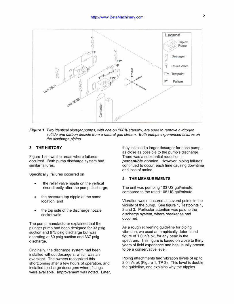
Piping attachments had vibration levels of up to2.0 in/s pk (Figure 1, TP 3). This level is doublethe guideline, and explains why the nipples
Figure 2 Vibration on the piping attachmentswas double the guideline.
failed. This vibration was not readily apparent tothe human touch, and it was later determined tobe a high frequency vibration. See Figure 2.
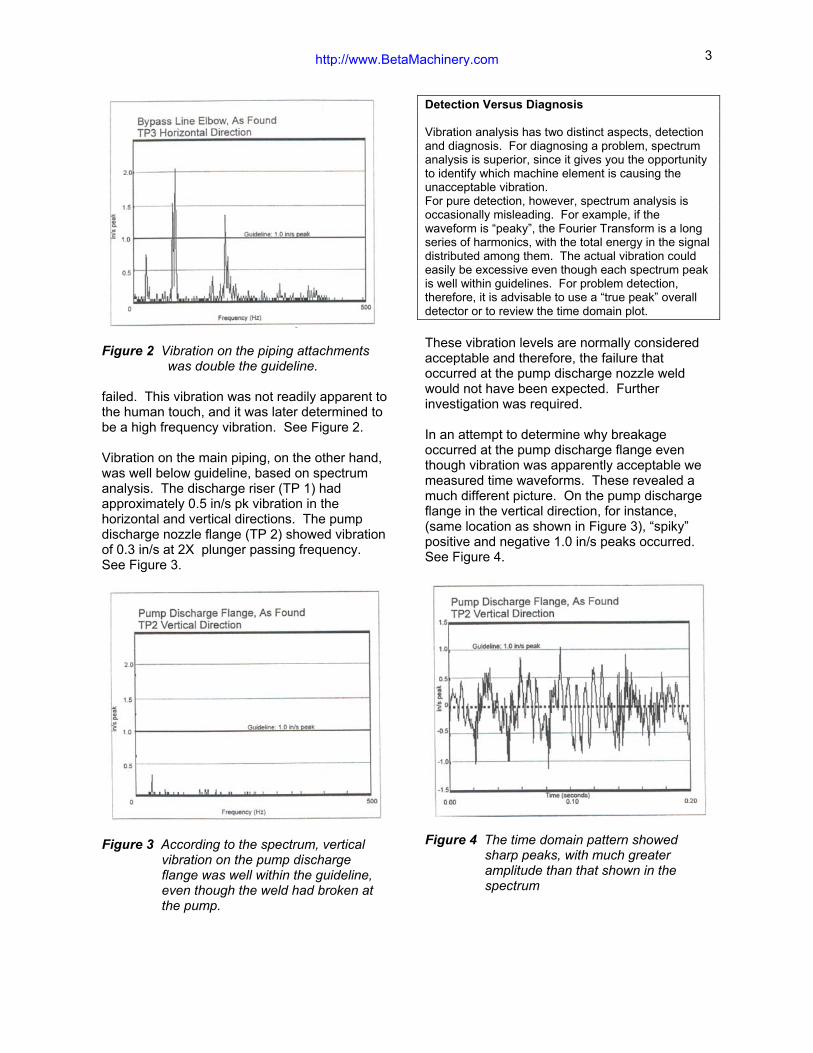
Vibration on the main piping, on the other hand,was well below guideline, based on spectrumanalysis. The discharge riser (TP 1) hadapproximately 0.5 in/s pk vibration in thehorizontal and vertical directions. The pumpdischarge nozzle flange (TP 2) showed vibrationof 0.3 in/s at 2X plunger passing frequency.See Figure 3.
Figure 3 According to the spectrum, verticalvibration on the pump dischargeflange was well within the guideline,even though the weld had broken atthe pump.
Detection Versus Diagnosis
Vibration analysis has two distinct aspects, detectionand diagnosis. For diagnosing a problem, spectrumanalysis is superior, since it gives you the opportunityto identify which machine element is causing theunacceptable vibration.For pure detection, however, spectrum analysis isoccasionally misleading. For example, if thewaveform is “peaky”, the Fourier Transform is a longseries of harmonics, with the total energy in the signaldistributed among them. The actual vibration couldeasily be excessive even though each spectrum peakis well within guidelines. For problem detection,therefore, it is advisable to use a “true peak” overalldetector or to review the time domain plot.
These vibration levels are normally consideredacceptable and therefore, the failure thatoccurred at the pump discharge nozzle weldwould not have been expected. Furtherinvestigation was required.
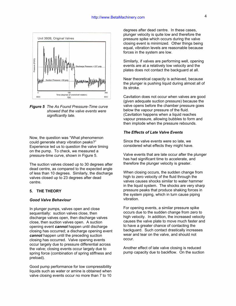
In an attempt to determine why breakageoccurred at the pump discharge flange eventhough vibration was apparently acceptable wemeasured time waveforms. These revealed amuch different picture. On the pump dischargeflange in the vertical direction, for instance,(same location as shown in Figure 3), “spiky”positive and negative 1.0 in/s peaks occurred.See Figure 4.
Figure 4 The time domain pattern showedsharp peaks, with much greateramplitude than that shown in thespectrum
Figure 5 The As Found Pressure-Time curveshowed that the valve events weresignificantly late.
Now, the question was “What phenomenoncould generate sharp vibration peaks?”Experience led us to question the valve timingon the pump. To check, we measured apressure-time curve, shown in Figure 5.
The suction valves closed up to 30 degrees afterdead centre, as compared to the expected angleof less than 10 degrees. Similarly, the dischargevalves closed up to 23 degrees after deadcentre.
5. THE THEORY
Good Valve Behaviour
In plunger pumps, valves open and closesequentially: suction valves close, thendischarge valves open, then discharge valvesclose, then suction valves open. A suctionopening event cannot happen until dischargeclosing has occurred; a discharge opening eventcannot happen until the preceding suctionclosing has occurred. Valve opening eventsoccur largely due to pressure differential acrossthe valve; closing events occur largely due tospring force (combination of spring stiffness andpreload).
Good pump performance for low compressibilityliquids such as water or amine is obtained whenvalve closing events occur no more than 7 to 10
degrees after dead centre. In these cases,plunger velocity is quite low and therefore thepressure spike which occurs during the valveclosing event is minimized. Other things beingequal, vibration levels are reasonable becauseforces in the system are low.
Similarly, if valves are performing well, openingevents are at a relatively low velocity and theplates does not contact the backguard at all.
Near theoretical capacity is achieved, becausethe plunger is pushing liquid during almost all ofits stroke.
Cavitation does not occur when valves are good(given adequate suction pressure) because thevalve opens before the chamber pressure goesbelow the vapour pressure of the fluid.(Cavitation happens when a liquid reachesvapour pressure, allowing bubbles to form andthen implode when the pressure rebounds.
The Effects of Late Valve Events
Since the valve events were so late, weconsidered what effects they might have.
Valve events that are late occur after the plungerhas had significant time to accelerate, andtherefore the plunger velocity is greater.
When closing occurs, the sudden change fromhigh to zero velocity of the fluid through thevalves causes shocks similar to water hammerin the liquid system. The shocks are very sharppressure peaks that produce shaking forces inthe system piping, which in turn cause pipingvibration.
For opening events, a similar pressure spikeoccurs due to the sudden change from zero tohigh velocity. In addition, the increased velocitycauses the valve plate to move much faster andto have a greater chance of contacting thebackguard. Such contact drastically increaseswear and tear on the valve, and should notoccur.
Another effect of late valve closing is reducedpump capacity due to backflow. On the suction
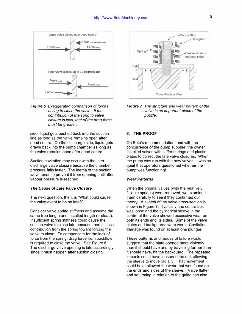
Figure 6 Exaggerated comparison of forcesacting to close the valve. If thecontribution of the sprig to valveclosure is less, that of the drag forcemust be greater.
side, liquid gets pushed back into the suctionline as long as the valve remains open afterdead centre. On the discharge side, liquid getsdrawn back into the pump chamber as long asthe valve remains open after dead centre.
Suction cavitation may occur with the laterdischarge valve closure because the chamberpressure falls faster. The inertia of the suctionvalve tends to prevent it from opening until aftervapour pressure is reached.
The Cause of Late Valve Closure
The next question, then, is “What could causethe valve event to be so late?”
Consider valve spring stiffness and assume thesame free length and installed length (preload).Insufficient spring stiffness could cause thesuction valve to close late because there is lesscontribution from the spring toward forcing thevalve to close. To compensate for the lack offorce from the spring, drag force from backflowis required to close the valve. See Figure 6.The discharge valve opening is late accordingly,since it must happen after suction closing.
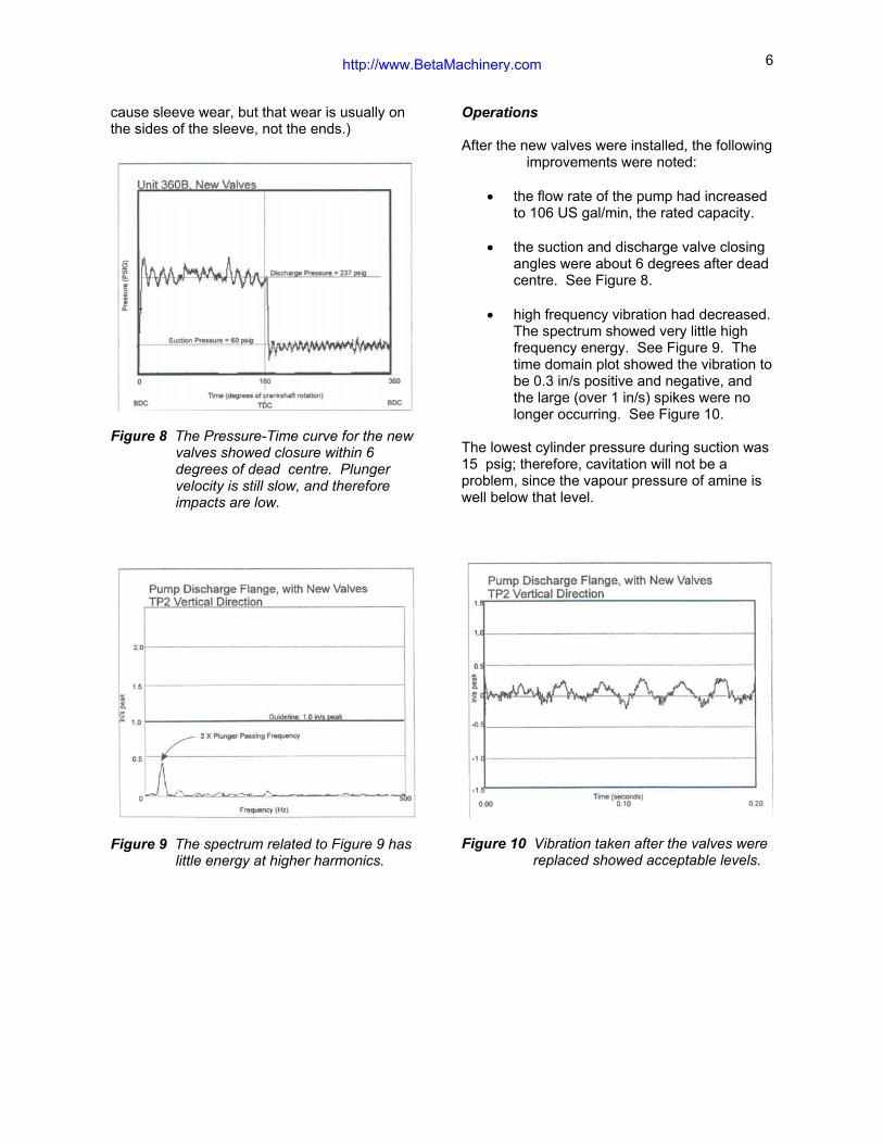
Figure 7 The structure and wear pattern of thevalve is an important piece of thepuzzle.
6. THE PROOF
On Beta’s recommendation, and with theconcurrence of the pump supplier, the ownerinstalled valves with stiffer springs and plasticplates to correct the late valve closures. Whenthe pump was run with the new valves, it was soquiet that operators questioned whether thepump was functioning!
Wear Patterns
When the original valves (with the relativelyflexible springs) were removed, we examinedthem carefully to see if they confirmed ourtheory. A sketch of the valve cross-section isshown in Figure 7. Typically, the centre boltwas loose and the cylindrical sleeve in thecentre of the valve showed excessive wear onboth its ends and its sides. Some of the valveplates and backguards were worn. Cavitationdamage was found on at least one plunger.
These patterns and modes of failure wouldsuggest that the plate opened more violentlythan it should have and by travelling farther thanit should have, hit the backguard. The repeatedimpacts could have loosened the nut, allowingthe sleeve to move radially. That movementcould have allowed the wear that was found onthe ends and sides of the sleeve. (Valve flutterand squirming in relation to the guide can also
cause sleeve wear, but that wear is usually onthe sides of the sleeve, not the ends.)
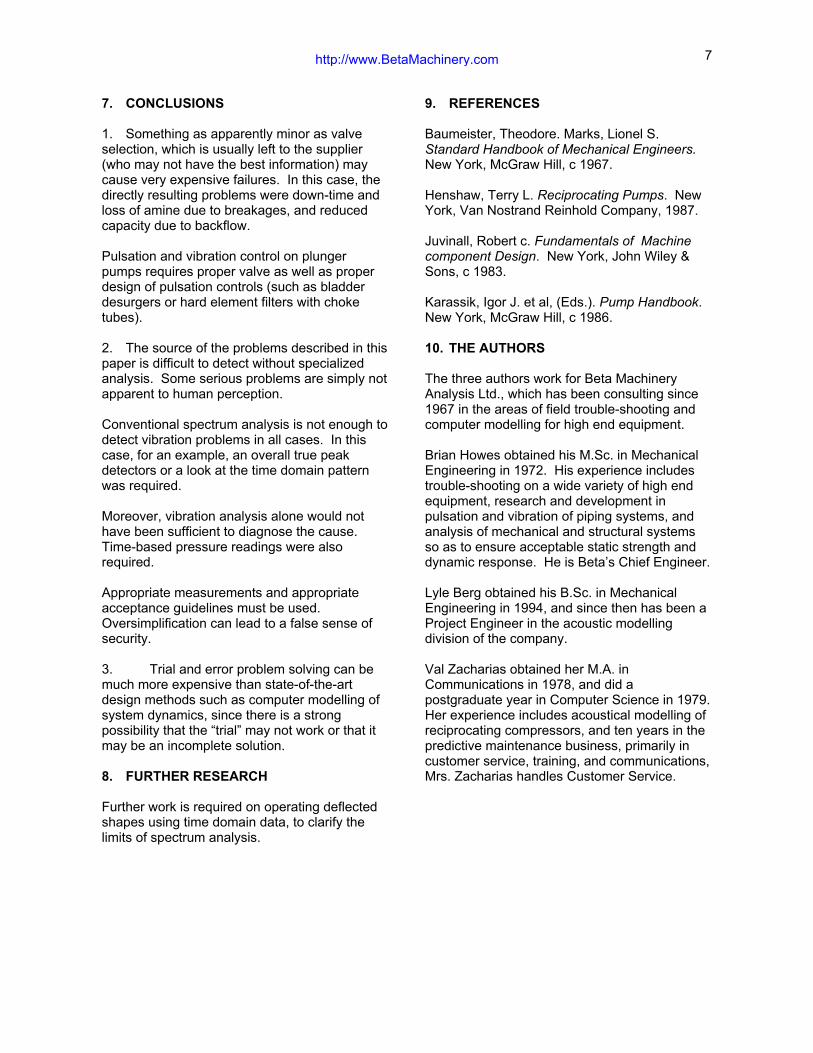
Figure 8 The Pressure-Time curve for the newvalves showed closure within 6degrees of dead centre. Plungervelocity is still slow, and thereforeimpacts are low.
Figure 9 The spectrum related to Figure 9 haslittle energy at higher harmonics.
Operations
After the new valves were installed, the followingimprovements were noted:
• the flow rate of the pump had increasedto 106 US gal/min, the rated capacity.
• the suction and discharge valve closingangles were about 6 degrees after deadcentre. See Figure 8.
• high frequency vibration had decreased.The spectrum showed very little highfrequency energy. See Figure 9. Thetime domain plot showed the vibration tobe 0.3 in/s positive and negative, andthe large (over 1 in/s) spikes were nolonger occurring. See Figure 10.
The lowest cylinder pressure during suction was15 psig; therefore, cavitation will not be aproblem, since the vapour pressure of amine iswell below that level.
Figure 10 Vibration taken after the valves werereplaced showed acceptable levels.
1. Something as apparently minor as valveselection, which is usually left to the supplier(who may not have the best information) maycause very expensive failures. In this case, thedirectly resulting problems were down-time andloss of amine due to breakages, and reducedcapacity due to backflow.
Pulsation and vibration control on plungerpumps requires proper valve as well as properdesign of pulsation controls (such as bladderdesurgers or hard element filters with choketubes).
2. The source of the problems described in thispaper is difficult to detect without specializedanalysis. Some serious problems are simply notapparent to human perception.
Conventional spectrum analysis is not enough todetect vibration problems in all cases. In thiscase, for an example, an overall true peakdetectors or a look at the time domain patternwas required.
Moreover, vibration analysis alone would nothave been sufficient to diagnose the cause.Time-based pressure readings were alsorequired.
Appropriate measurements and appropriateacceptance guidelines must be used.Oversimplification can lead to a false sense ofsecurity.
3. Trial and error problem solving can bemuch more expensive than state-of-the-artdesign methods such as computer modelling ofsystem dynamics, since there is a strongpossibility that the “trial” may not work or that itmay be an incomplete solution.
8. FURTHER RESEARCH
Further work is required on operating deflectedshapes using time domain data, to clarify thelimits of spectrum analysis.
9. REFERENCES
Baumeister, Theodore. Marks, Lionel S.Standard Handbook of Mechanical Engineers.New York, McGraw Hill, c 1967.
Henshaw, Terry L. Reciprocating Pumps. NewYork, Van Nostrand Reinhold Company, 1987.
Juvinall, Robert c. Fundamentals of Machinecomponent Design. New York, John Wiley &Sons, c 1983.
Karassik, Igor J. et al, (Eds.). Pump Handbook.New York, McGraw Hill, c 1986.
10. THE AUTHORS
The three authors work for Beta MachineryAnalysis Ltd., which has been consulting since1967 in the areas of field trouble-shooting andcomputer modelling for high end equipment.
Brian Howes obtained his M.Sc. in MechanicalEngineering in 1972. His experience includestrouble-shooting on a wide variety of high endequipment, research and development inpulsation and vibration of piping systems, andanalysis of mechanical and structural systemsso as to ensure acceptable static strength anddynamic response. He is Beta’s Chief Engineer.
Lyle Berg obtained his B.Sc. in MechanicalEngineering in 1994, and since then has been aProject Engineer in the acoustic modellingdivision of the company.
Val Zacharias obtained her M.A. inCommunications in 1978, and did apostgraduate year in Computer Science in 1979.Her experience includes acoustical modelling ofreciprocating compressors, and ten years in thepredictive maintenance business, primarily incustomer service, training, and communications,Mrs. Zacharias handles Customer Service.