.lu software verification & validation V V S Incremental Reconfiguration of Product Specific Use Case Models for Evolving Configuration Decisions Ines Hajri, Arda Goknil, Lionel Briand, and Thierry Stephany SnT Center, University of Luxembourg IEE, Luxembourg
Transcript
.lusoftware verification & validationVVSIncremental Reconfiguration of
Product Specific Use Case Models for Evolving Configuration Decisions
Ines Hajri, Arda Goknil, Lionel Briand, and Thierry Stephany
SnT Center, University of LuxembourgIEE, Luxembourg
Context: Automotive Domain
2
International Electronics & Engineering
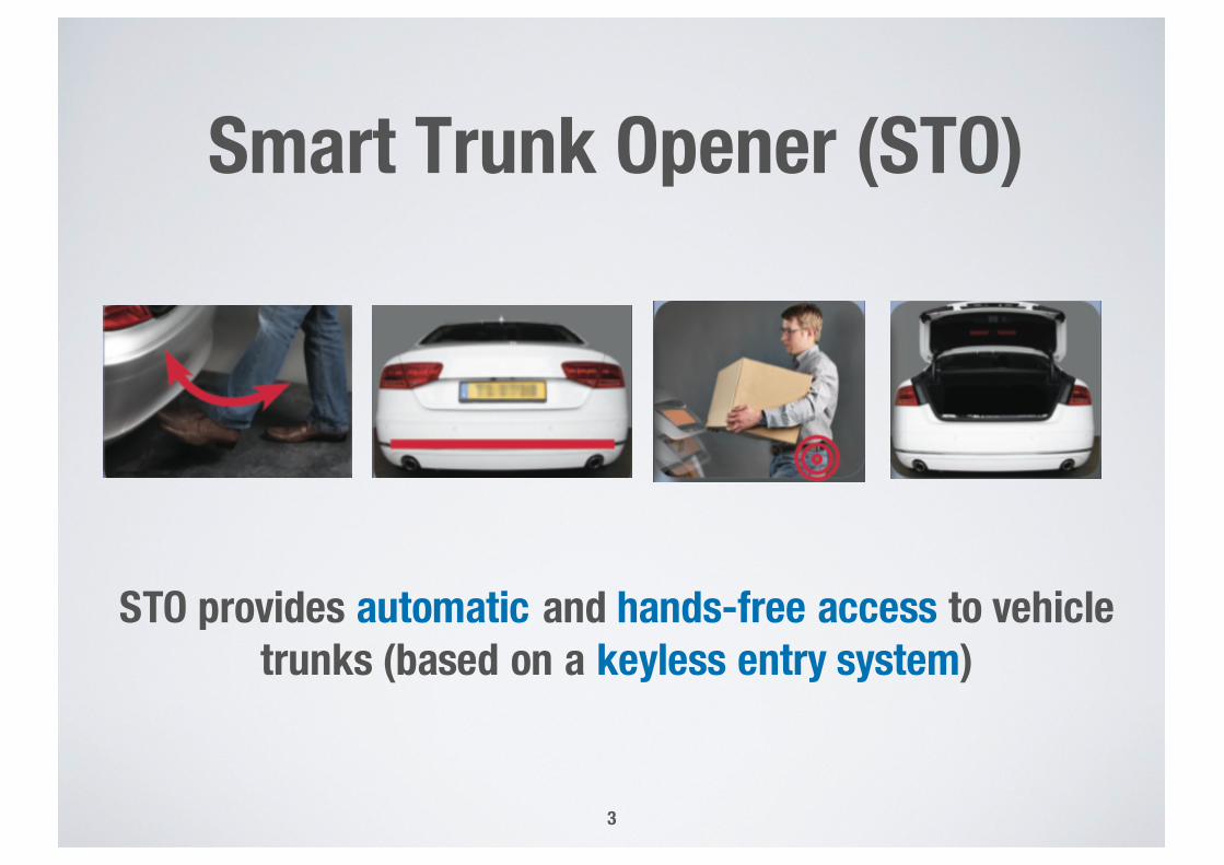
Smart Trunk Opener (STO)
STO provides automatic and hands-free access to vehicle trunks (based on a keyless entry system)
3
Context: Use Case Driven Development in Product Lines
4
Use case Diagram
Use Case SpecificationsActor Request
Order
Show catalog
Pay For
Products are developed for multiple customers with varyingneeds in a product line
Context: Evolution of Requirements
5
STO Requirements from Customer A
(Use Case Diagram and Specifications)
Customer Afor STO
STO Test Cases for Customer A
Derived from
STO Requirements from Customer B
(Use Case Diagram and Specifications)
Customer Bfor STO
STO Test Cases for Customer B
Derived from
evolves to
(clone-and-own)
modify modify
evolves to
(clone-and-own)
STO Requirements from Customer C
(Use Case Diagram and Specifications)
modify
Customer Cfor STO
STO Test Cases for Customer C
Derived from
Long Term ObjectiveSupport:
• automated and effective change management,
• and regression test selection
in the context of:
• product lines,
• and use case-driven development and testing
6
Research Steps
• Step1: Product line Use case modeling Method (PUM)[MODELS’15]
• Step2: Product line Use case Model Configurator (PUMConf) [SoSyM’16]
• Step3: Supporting incremental reconfiguration of use case models for evolving configuration decisions[This paper]
7
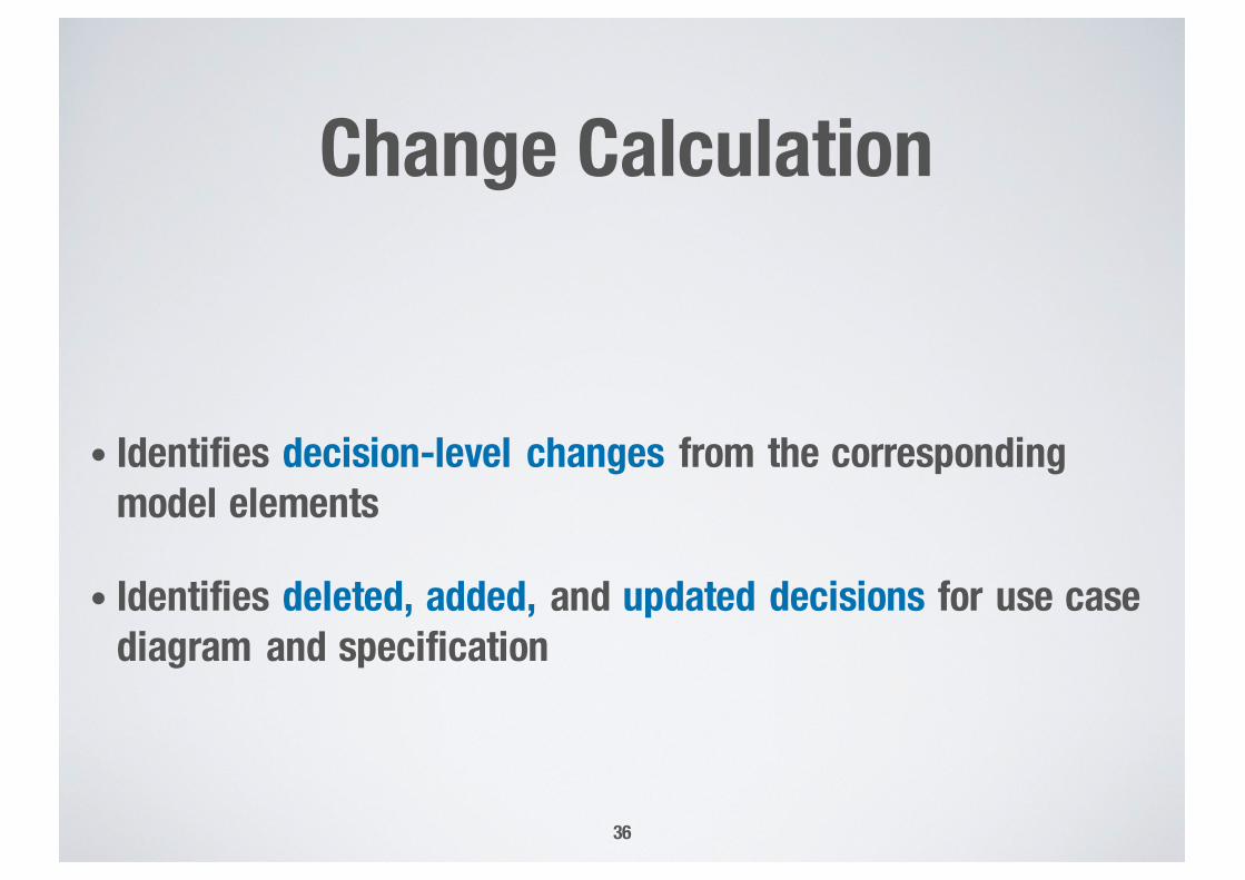
Incremental Reconfiguration
• Main goal: reduce manual effort during reconfiguration- In particular, reducing the effort of manually assigning
traceability links between product specific use case models and external documents
• Approach: product specific use case models can be incrementally regenerated by exclusively focusing on the changed decisions and their side effects
8
Background
Product Line Use Case Modeling Method: PUM
10
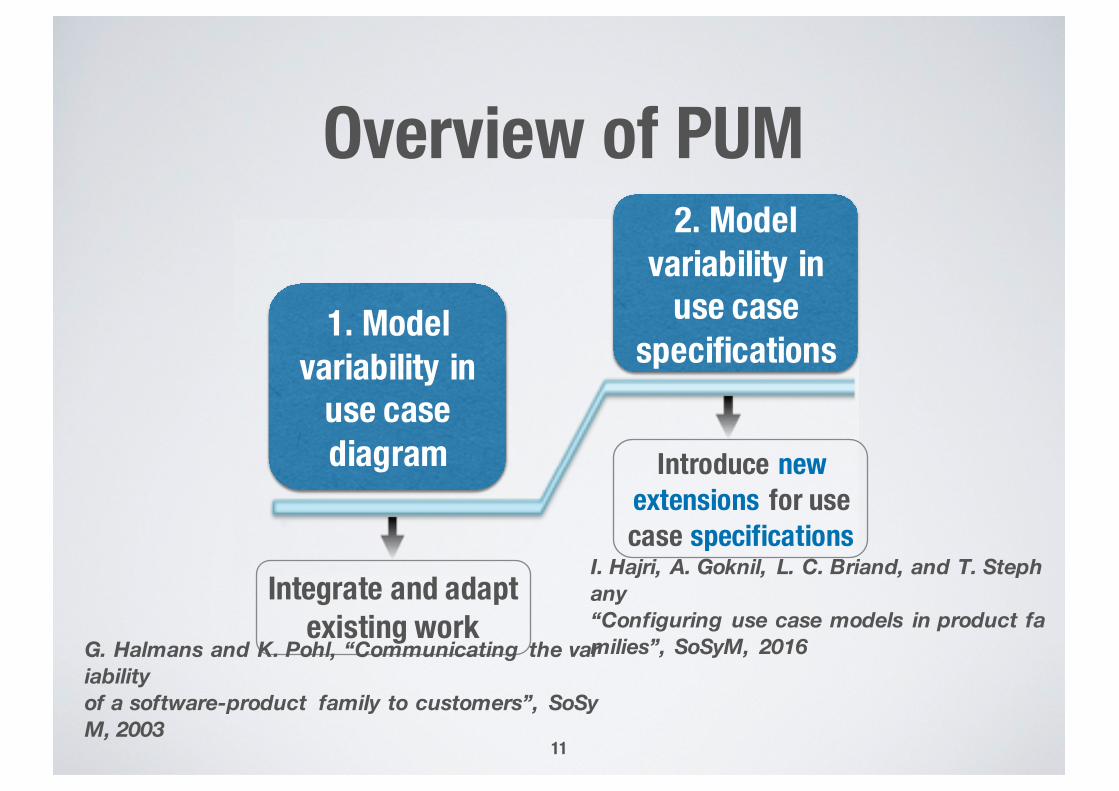
Overview of PUM
11
2. Model variability in
use case specifications
1. Model variability in
use case diagram Introduce new
extensions for use case specifications
Integrate and adapt existing work
G. Halmans and K. Pohl, “Communicating the variability of a software-product family to customers”, SoSyM, 2003
I. Hajri, A. Goknil, L. C. Briand, and T. Stephany“Configuring use case models in product families”, SoSyM, 2016
Product Line Use Case Diagram
12
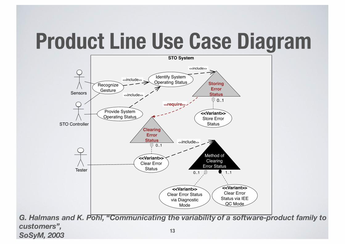
Product Line Use Case Diagram
13
STO System
SensorsRecognize
Gesture
Identify System Operating Status Storing
Error Status
Provide System Operating Status
Tester
<<include>>
<<Variant>>Store Error
Status
<<include>>
Clearing Error
Status
<<Variant>>Clear Error
Status
0..1
0..1
<<Variant>>Clear Error Status
via Diagnostic Mode
<<Variant>>Clear Error
Status via IEE QC Mode
0..1
<<include>>
Method of Clearing
Error Status 1..1
<<require>>
STO Controller
<<include>>
G. Halmans and K. Pohl, “Communicating the variability of a software-product family to customers”, SoSyM, 2003
Product Line Use Case Specifications
14
Restricted Use Case Modeling: RUCM
15
• RUCM is based on: - Predefined template- Restriction rules- Specific keywords
• RUCM reduces ambiguities and facilitates automated analysis of use cases
T. Yue, L. C. Briand, and Y. Labiche, “Facilitating the transition from use case models to analysis models: Approach and experiments”, TOSEM, 2013.
RUCM Extensions
New keywords for modeling variability in use case specifications:• INCLUDE VARIATION POINT: for including variation points
• VARIANT: for variability in use cases
• OPTIONAL: for variability in steps and alternative flows
• V: for variability in steps order
16
Example Product Line Use Case Specifications
17
Configuration Approach for Use Case-Driven Development
18
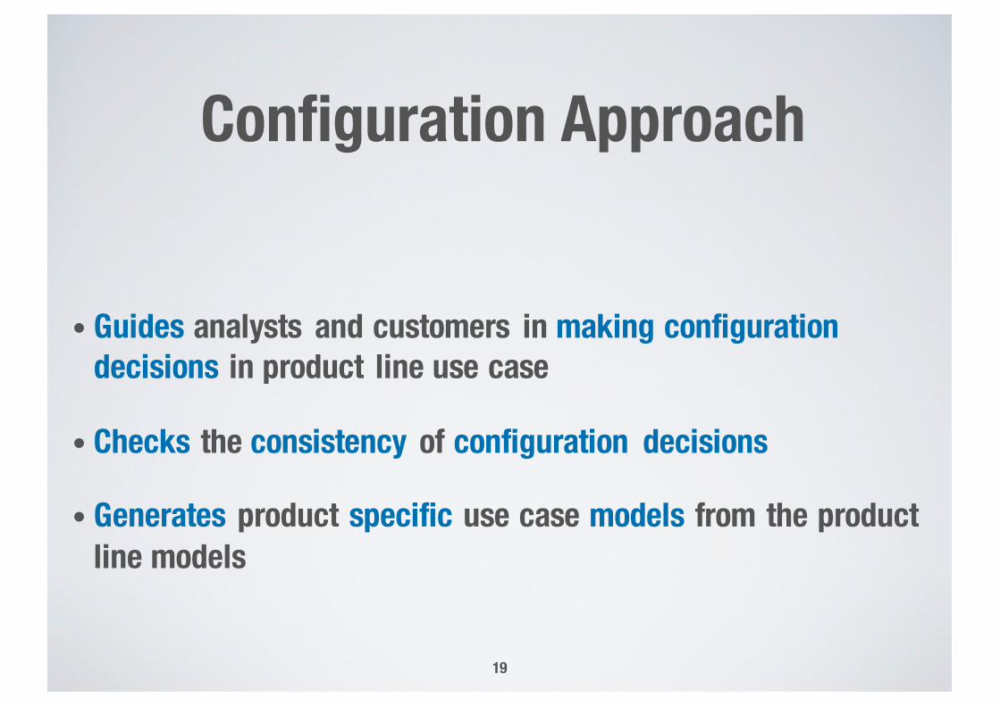
Configuration Approach
• Guides analysts and customers in making configuration decisions in product line use case
• Checks the consistency of configuration decisions
• Generates product specific use case models from the product line models
19
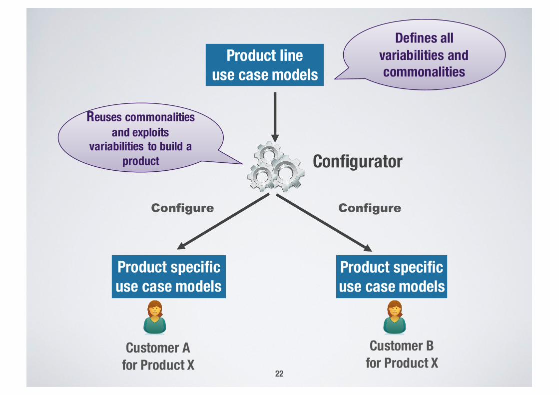
Product specific use case models
Customer Afor Product X
Product lineuse case models
Customer Bfor Product X
Product specific use case models
ConfigureConfigure
Defines all variabilities and commonalities
Reuses commonalities and exploits
variabilities to build a product
20
Configurator
Incremental Reconfiguration of PS Models for Evolving Configuration
Decisions
Product specific use case models
Customer Afor Product X
Product lineuse case models
Customer Bfor Product X
Product specific use case models
ConfigureConfigure
Defines all variabilities and commonalities
Reuses commonalities and exploits
variabilities to build a product Configurator
22
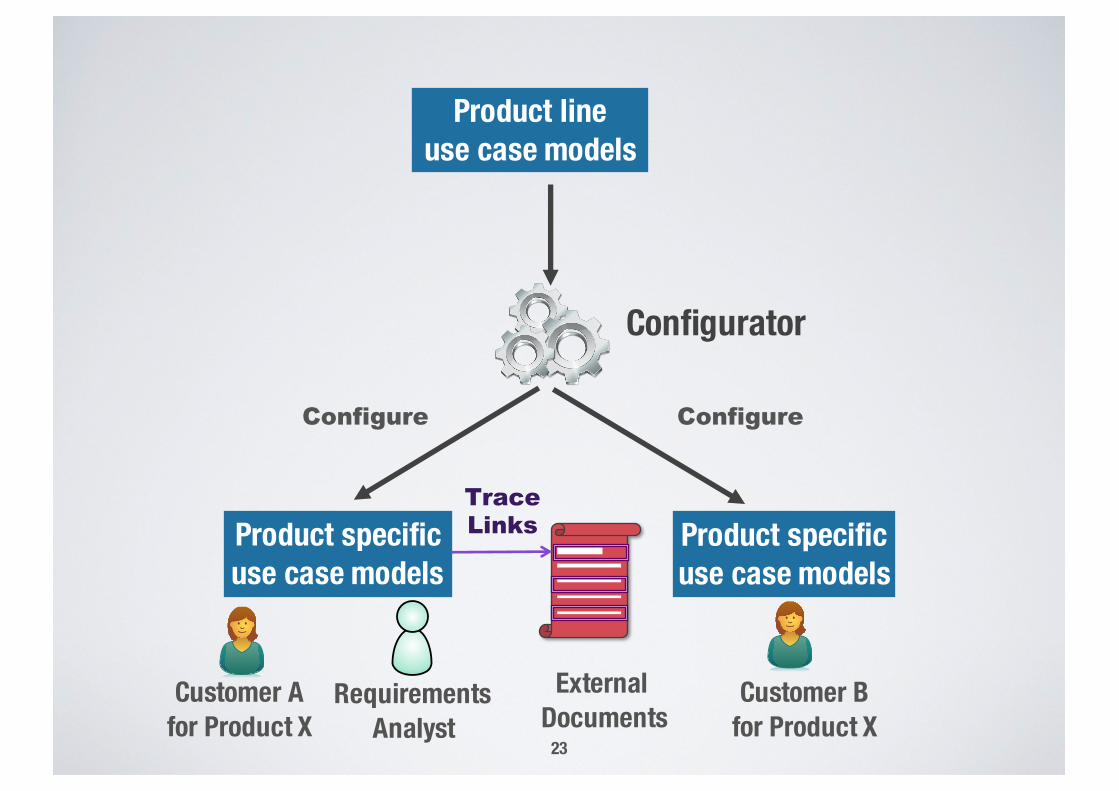
Product specific use case models
Customer Afor Product X
Product lineuse case models
Customer Bfor Product X
Product specific use case models
ConfigureConfigure
Configurator
Requirements Analyst
TraceLinks
23
External Documents
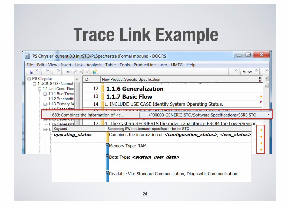
Trace Link Example
24
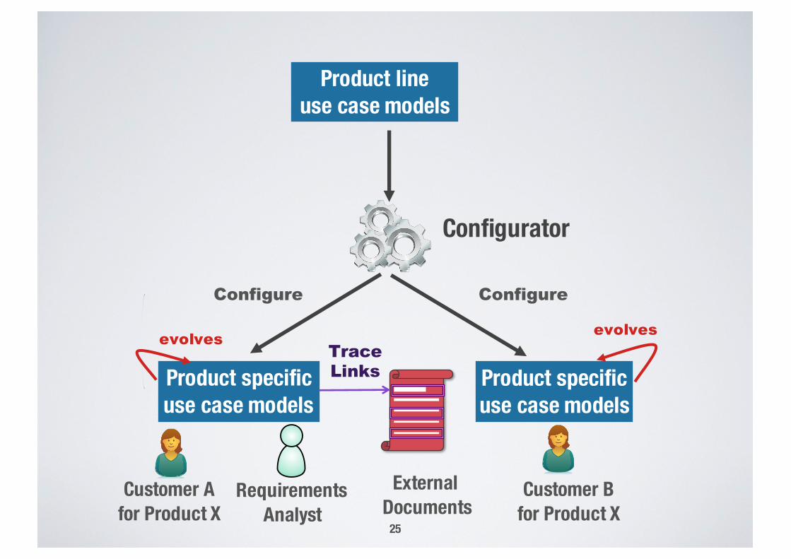
Product specific use case models
Customer Afor Product X
Product lineuse case models
Customer Bfor Product X
Product specific use case models
ConfigureConfigure
Configurator
Requirements Analyst
TraceLinks
25
External Documents
evolvesevolves
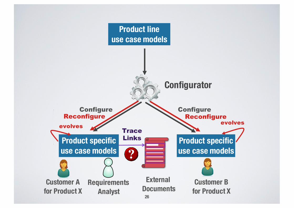
Product specific use case models
Customer Afor Product X
Product lineuse case models
Customer Bfor Product X
Product specific use case models
ConfigureConfigure
Configurator
Requirements Analyst
TraceLinks
26
External Documents
evolvesevolvesReconfigure Reconfigure
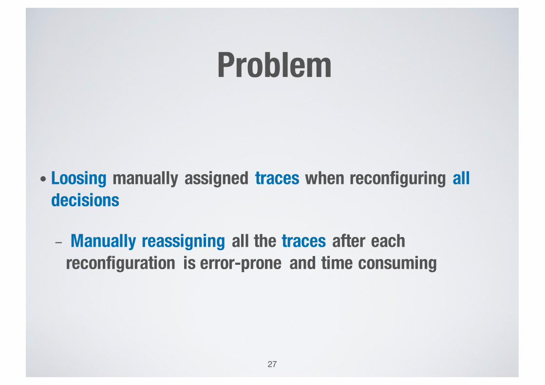
Problem
• Loosing manually assigned traces when reconfiguring all decisions
- Manually reassigning all the traces after each reconfiguration is error-prone and time consuming
27
Goal
• Avoid manual effort during reconfiguration by incrementally reconfiguring the generated product specific models exclusively for the changed decisions
- Preserve non-impacted parts of product specific use case models and their a-priori assigned traces
- Inform analysts about the impact of changes on configuration decisions for product line models
28
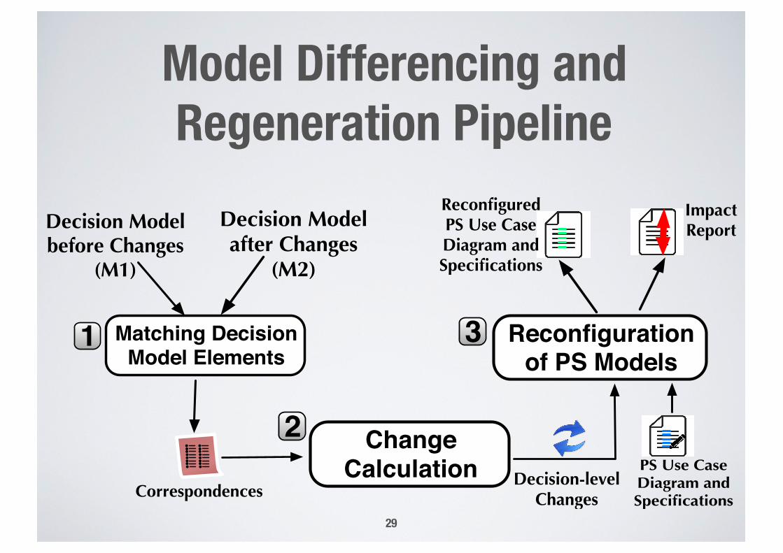
Model Differencing and Regeneration Pipeline
29
Decision Model before Changes
(M1)
Decision Model after Changes
(M2)
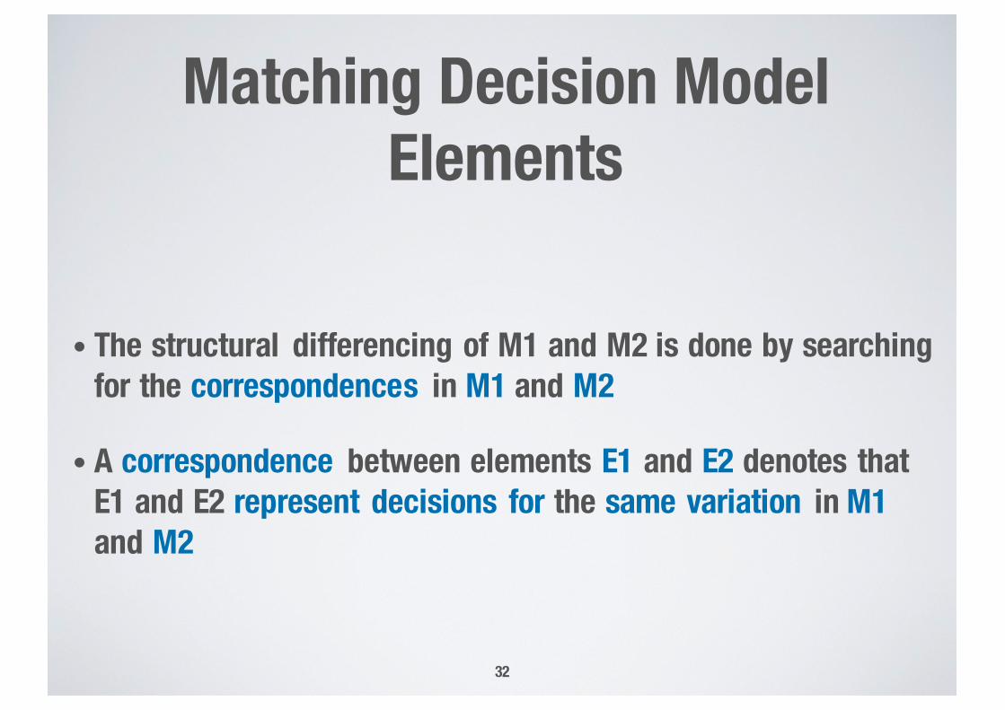
Matching Decision Model Elements
1
Correspondences
•• •• •• •• •• •• •• ••
2 Change Calculation
Reconfiguration of PS Models
3
Decision-levelChanges
PS Use Case Diagram and Specifications
ReconfiguredPS Use Case Diagram and Specifications
Impact Report
Matching Decision Model Elements
30
Decision Model before Changes
(M1)
Decision Model after Changes
(M2)
Matching Decision Model Elements
1
Correspondences
•• •• •• •• •• •• •• ••
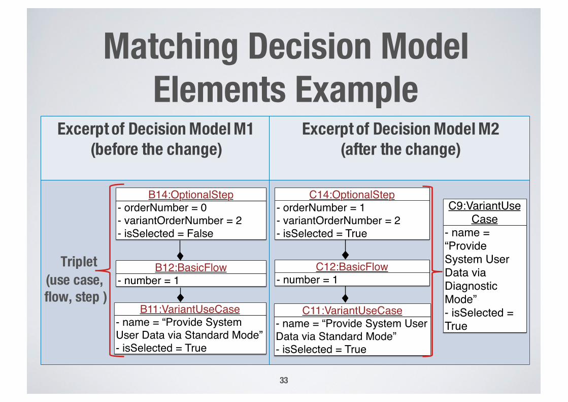
Decision Model Example
31
:DecisionModel- name = “Provide System User Data”
:EssentialUseCase
- name = “Method of Providing Data”:MandatoryVariationPoint
- name = “Provide System User Data via Standard Mode”- isSelected = True
:VariantUseCase- name = “Provide System User Data via Diagnostic Mode”- isSelected = True
:VariantUseCase- name = “Provide System User Data via IEE QC Mode”- isSelected = True
- name = “Provide System User Data via Diagnostic Mode”- isSelected = True
C9:VariantUseCase
Reconfiguration of Product Specific Models
38
Decision Model before Changes
(M1)
Decision Model after Changes
(M2)
Matching Decision Model Elements
1
Correspondences
•• •• •• •• •• •• •• ••
2 Change Calculation
Reconfiguration of PS Models
3
Decision-levelChanges
PS Use Case Diagram and Specifications
ReconfiguredPS Use Case Diagram and Specifications
Impact Report
Reconfiguration of Product Specific Models
• Regenerates the product specific use case diagram and specifications only for the added, deleted, and updateddecisions
• Generates a report for the impacted and regenerated parts of the product specific models
39
Reconfiguration of PS Models Example
40
Impact Report Example
41
Evaluation
42
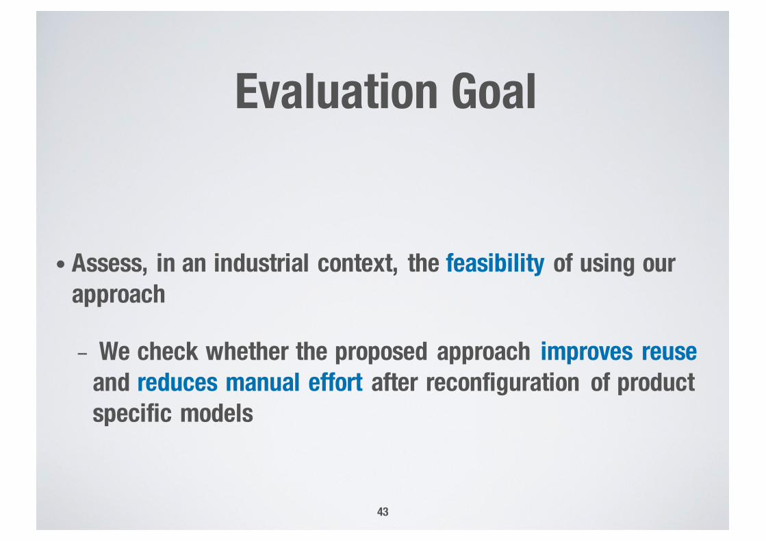
Evaluation Goal
• Assess, in an industrial context, the feasibility of using our approach
- We check whether the proposed approach improves reuse and reduces manual effort after reconfiguration of product specific models
43
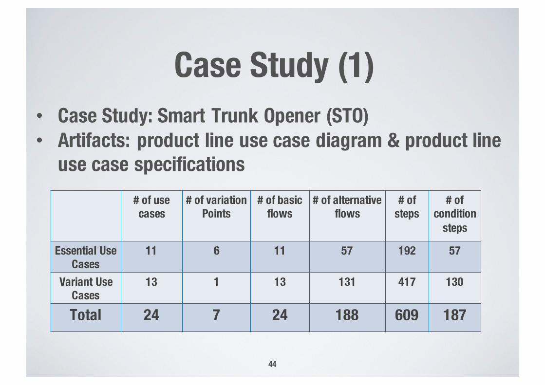
Case Study (1)
44
# of use cases
# of variation Points
# of basic flows
# of alternative flows
# of steps
# of condition
steps
Essential Use Cases
11 6 11 57 192 57
Variant Use Cases
13 1 13 131 417 130
Total 24 7 24 188 609 187
• Case Study: Smart Trunk Opener (STO)• Artifacts: product line use case diagram & product line
use case specifications
Case Study (2)
• We configured product specific models for 4 products
• We chose 1 product to be used for reconfiguration
• The selected product includes: - 36 traces from product specific use case diagram- 278 traces from product specific use case specifications to
other requirements documents
• We considered 8 change scenarios 45
Example Change Scenarios
46
ID Change Scenario ExplanationS1 Update a diagram decision Unselecting selected use cases
S2 Update and delete diagram decisions
Unselecting selected use cases, removing other decisions
S3 Update and add diagram decisions Selecting unselected use cases, implying other decisions
…
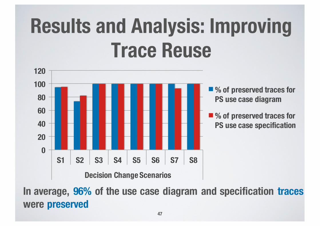
Results and Analysis: Improving Trace Reuse
47
020406080
100120
S1 S2 S3 S4 S5 S6 S7 S8
Decision Change Scenarios
% of preserved traces for PS use case diagram
% of preserved traces for PS use case specification
In average, 96% of the use case diagram and specification traces were preserved
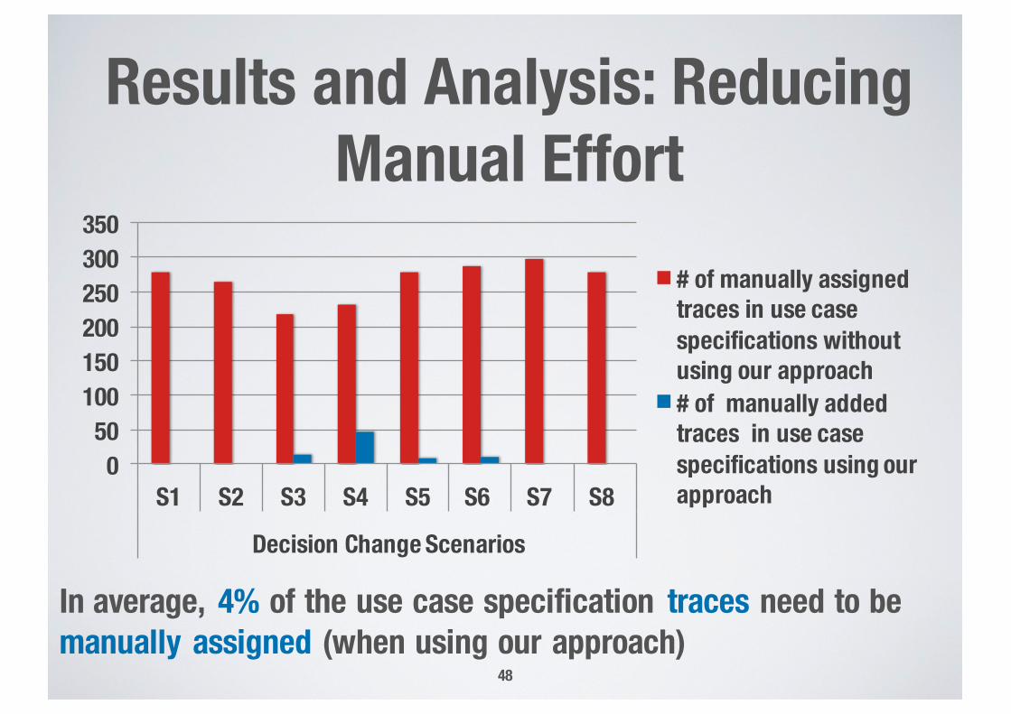
Results and Analysis: Reducing Manual Effort
48
In average, 4% of the use case specification traces need to be manually assigned (when using our approach)
050
100150200250300350
S1 S2 S3 S4 S5 S6 S7 S8
Decision Change Scenarios
# of manually assigned traces in use case specifications without using our approach# of manually added traces in use case specifications using our approach
Evaluation Summary
• Our approach preserved all the traces for the unchanged parts of PS models
• Only the traces for the deleted parts of the PS models were removed
• Our automated approach for incremental reconfiguration leads to significant reuse and savings when updating traces
49
Future Work
• Change impact analysis in the context of product lines
• Regression test selection in the context of product lines
50
Summing up
52
.lusoftware verification & validationVVSIncremental Reconfiguration of
Product Specific Use Case Models for Evolving Configuration Decisions
Ines Hajri, Arda Goknil, Lionel Briand, and Thierry Stephany
SnT Center, University of LuxembourgIEE, Luxembourg