189
Operating manual 2013-05-15 Multitron Pro Incubation Shaker Dok-ID: V.02.000 - Original

Operating manual
2013-05-15
Multitron Pro Incubation Shaker
Dok-ID: V.02.000 - Original
Page 2 of 188 15 May 2013
Infors AG Headoffice, Schweiz Rittergasse 27 CH-4103 Bottmingen T +41 (0)61 425 77 00 F +41 (0)61 425 77 01 [email protected] [email protected]
Infors GmbH Dachauer Str. 6 D-85254 Einsbach T +49 (0)8135 8333 F +49 (0)8135 8320 [email protected]
Infors UK Ltd The Courtyard Business Centre Dovers Farm, Lonesome Lane, Reigate Surrey, RH2 7QT, UK T +44 (0)1737 22 31 00 F +44 (0)1737 24 72 13 [email protected]
Infors Sarl 2, rue du Buisson aux Fraises Bâtiment D13 F-91300 Massy T +33 (0)1 69 30 95 04 F +33 (0)1 69 30 95 05 [email protected]
Infors Benelux BV Fabriekstraat 38 7005 AR Doetinchem P.O. Box 613 NL-7000 AP Doetinchem T +31 (0)314 36 44 50 F +31 (0)314 37 80 76 [email protected]
Contact details of our local dealers worldwide can be found on our website www.infors-ht.com
Infors Canada 8350 rue Bombardier Anjou, Quebec Canada H1J 1A6 T +1 514 352 5095 F +1 514 352 5610 [email protected]
Infors Bio-Technology (Beijing) Co., Ltd. Room 505C, Building 106 Lize Zhongyuan Wangjing New Industrial Zone Chaoyang District, Beijing 100102 P.R. of China T +86 10 51652068 F +86 10 64390585 [email protected]
Infors South East Asia 16, 1st Floor, Taman City MY-51200 Kuala Lumpur Malaysia T +603 625 771 81 F +603 625 067 48 [email protected]
Engineering and production in Switzerland

Multitron Pro - Incubation Shaker
Table of Contents
15 May 2013 Page 3 of 188
1 General Information .............................................................7 1.1 About this Manual ........................................................7 1.2 Symbols ......................................................................8 1.3 Limitation of Liability ....................................................9 1.4 Copyright Protection .................................................. 10 1.5 Spare parts ................................................................ 10 1.6 Terms of Guarantee ................................................... 10 1.7 Customer Service ...................................................... 10 1.8 Declaration of Conformity........................................... 11
2 Safety ................................................................................. 12 2.1 Responsibility of the operator ..................................... 12 2.2 Requirements for qualified personnel ......................... 13
2.2.1 Unauthorised persons ................................. 14 2.3 Conventional use of the equipment ............................ 14 2.4 Personal protective equipment ................................... 16 2.5 Particular hazards ...................................................... 16 2.6 Step to take in the event of hazardous situations and
at accidents ............................................................... 19 2.7 Environmental protection ........................................... 19 2.8 Adhesive labels / signs / symbols ............................... 20
3 Technical data.................................................................... 21 3.1 Dimensions................................................................ 21 3.2 Weights ..................................................................... 27 3.3 Connection values ..................................................... 30 3.4 Specifications ............................................................ 37 3.5 Operating conditions .................................................. 50 3.6 Emissions .................................................................. 51 3.7 Utilities....................................................................... 51 3.8 Identification plate ...................................................... 52 3.9 Interface communication protocol............................... 52
4 Setup and function ............................................................ 53 4.1 Base unit ................................................................... 53 4.2 Basic Functions ......................................................... 58 4.3 Messages .................................................................. 59 4.4 Serial interface........................................................... 61 4.5 Option Analog Interface ............................................. 62 4.6 Option bases ............................................................. 63 4.7 Operating panel ......................................................... 64
4.7.1 Operating panel symbols............................. 66 4.7.2 Operating panel displays ............................. 68

Multitron Pro Incubation Shaker
Table of Contents
Page 4 of 188 15 May 2013
4.7.3 Operating panel keys .................................. 69 4.8 Option cooling system ............................................... 70 4.9 Option «Sticky Stuff» adhesive matting ...................... 72 4.10 Option Direct Steam Humidification............................ 72 4.11 Option CO2 gassing ................................................... 73 4.12 Option Reduction Station for CO2 gassing.................. 76 4.13 Optional Illumination .................................................. 76 4.14 Option “Algae” Illumination ......................................... 78 4.15 Option Pass-through .................................................. 79 4.16 Option Mobile Pt100 sensor ....................................... 80 4.17 Option Adjustable counterweight................................ 82 4.18 Option UV sterilisation of the air supply ...................... 83
5 Transport, packaging and storage.................................... 84 5.1 Safety instructions for transport ................................. 84 5.2 Transport inspection .................................................. 84 5.3 Packaging ................................................................. 85 5.4 Transport ................................................................... 85 5.5 Storage of the incubator shaker ................................. 86
6 Installation and initial operation ....................................... 87 6.1 Safety ........................................................................ 87 6.2 Location requirements for installation ......................... 88
6.2.1 Place of installation ..................................... 88 6.2.2 Minimum distances ..................................... 89
6.3 Removing the transport lock ...................................... 90 6.4 Mounting the drain nozzle .......................................... 91 6.5 Switching on the unit.................................................. 92 6.6 Installing the incubator shaker ................................... 93 6.7 Setting the capillary thermostat .................................. 95 6.8 Setting the adjustable counterweight.......................... 96
6.8.1 Changing the throw ..................................... 97 6.8.2 Adjusting the detachable counterweights .... 99
6.9 Switching on the cooling system .............................. 100 6.10 Filling with cooling liquid .......................................... 101
6.10.1 Top-mounted cooling system .................... 102 6.11 Connecting the external cooling system ................... 103 6.12 Connecting the Direct Steam Humidification ............ 104 6.13 Connecting the CO2 gas supply ............................... 106 6.14 Connecting the gassing pipe .................................... 106
7 Operation ......................................................................... 107 7.1 Safety ...................................................................... 107

Multitron Pro - Incubation Shaker
Table of Contents
15 May 2013 Page 5 of 188
7.2 Switching on the unit ................................................ 108 7.3 General operation .................................................... 109 7.4 Operating the timer .................................................. 112
7.4.1 Displaying the time .................................... 112 7.4.2 Continuous operation without timer ........... 113 7.4.3 Setting the timer ........................................ 113 7.4.4 Setting the timer for a single changeover ... 114 7.4.5 Setting the timer for multiple changeovers
(cycling) .................................................... 115 7.4.6 Display the remaining runtime of the timer . 116
7.5 Selecting a unit in a stack ........................................ 117 7.6 Starting a work cycle ................................................ 119 7.7 Ending a work cycle ................................................. 122 7.8 Stopping shaker table .............................................. 123 7.9 Testing the alarm function ........................................ 123 7.10 Alarm messages ...................................................... 124 7.11 Operating the tray .................................................... 125 7.12 Handling the flasks without pulling out the tray ......... 129 7.13 Loading the trays ..................................................... 129 7.14 Using the «Sticky Stuff» adhesive matting ................ 131 7.15 Interrupting operation ............................................... 132 7.16 Operating the UV sterilisation................................... 133 7.17 Operating the Direct Steam Humidification ............... 133 7.18 Operating the cooling system ................................... 134 7.19 Starting illumination ................................................. 135 7.20 Starting algae illumination ........................................ 137 7.21 Operating the CO2 gassing system .......................... 137 7.22 Setting the pressure reduction station for CO2
gassing .................................................................... 139 7.23 Using the gassing pipe............................................. 139 7.24 Operating the mobile Pt100 sensor .......................... 139 7.25 Setting up the pass-through ..................................... 140
8 Maintenance ..................................................................... 143 8.1 Safety ...................................................................... 143 8.2 Environmental protection ......................................... 145 8.3 Maintenance plan .................................................... 145 8.4 Replacing the fuse ................................................... 147 8.5 Cleaning the cooling system .................................... 147 8.6 Illumination .............................................................. 149
8.6.1 Replacing fluorescent tubes ...................... 149 8.6.2 Replacing the starter ................................. 150

Multitron Pro Incubation Shaker
Table of Contents
Page 6 of 188 15 May 2013
8.7 Cleaning the algae illumination ................................ 150 8.8 Replacing the feed hose of the Direct Steam
Humidification .......................................................... 151 8.9 Replacing the «Sticky Stuff» adhesive matting ......... 151 8.10 Cleaning .................................................................. 152 8.11 Cleaning the glass door pane .................................. 152
8.11.1 Cleaning the housing ................................ 153 8.11.2 Cleaning the chamber ............................... 153 8.11.3 Cleaning the floor pan ............................... 153 8.11.4 Cleaning the trays ..................................... 155
8.12 Cleaning the «Sticky Stuff» adhesive matting ........... 155 8.13 CO2 curtain ............................................................. 156 8.14 Finishing maintenance work..................................... 156
9 Interferences .................................................................... 157 9.1 Safety ...................................................................... 159 9.2 Tables of interferences ............................................ 160 9.3 Error messages ....................................................... 160 9.4 Interference Illumination broken tube ....................... 167 9.5 Returning for repair .................................................. 168
10 Disassembly .................................................................... 169 10.1 Safety ...................................................................... 169 10.2 Disassembly ............................................................ 170 10.3 Disposal .................................................................. 171
11 Examples ......................................................................... 172 11.1 Delay a speed change ............................................. 172 11.2 Switch-on delay ....................................................... 174 11.3 Cyclic operation ....................................................... 176
12 Appendix .......................................................................... 179 12.1 Circuit diagram ........................................................ 179 12.2 Additional information of the use of sterile filters ....... 180 12.3 Purifying Methods .................................................... 181 12.4 Roxtec EzEntry 4 Mini ............................................. 183
13 Index ................................................................................ 185
Multitron Pro - Incubation Shaker
General Information
15 May 2013 Page 7 of 188
1 General Information
1.1 About this Manual This manual enables the safe and efficient handling of the equipment. This manual is a component part of the equipment. It must be kept near to the equipment and must be accessible to the operators at all times. The operators must read thoroughly and fully understand this manual before commencement of any work.
Adhering to all the points, advice and instructions concerning safety and operation in this operating manual is a pre-condition for safe working.
Furthermore, local rules for accident prevention and general safety regulations relevant to the equipment’s field of application may be in force. This manual contains pictures which aid general understanding and can differ from the actual equipment as supplied.
NOTICE! Application notes are available for several issues. They are provided as PDF-Downloads on the website of the manufacturer.
Multitron Pro - Incubation Shaker
General Information
Page 8 of 188 15 May 2013
1.2 Symbols
Safety Instructions Safety instructions are labeled using symbols. All safety instructions begin with a word that signifies the degree of hazard. Strictly follow all safety points and act with due caution to avoid accidents, damage to equipment, personal injuries and loss of property.
DANGER! … points out an immediate, dangerous situation that leads to death or severe injuries unless avoided.
WARNING! … points out a potentially dangerous situation that may lead to death or severe injuries unless avoided.
CAUTION! … points out a possibly dangerous situation that leads to slight or minor injuries unless avoided.
CAUTION! … points out a possibly dangerous situation that leads to damage to property unless avoided.
Hints and Recommendations
NOTICE! … highlights useful hints and recommendations as well as information for safe and efficient use of the equipment.

Multitron Pro - Incubation Shaker
General Information
15 May 2013 Page 9 of 188
Specific Safety Instructions The following safety instructions are used to call attention to particular hazards.
DANGER! Danger of fatal electric shock! …signifies danger by electric current. Non-observance of safety instructions may lead to a severe or fatal physical injury.
WARNING! Danger of infectious substances! … signifies danger by infectious substances (e.g. liquids which contain bacteria or viruses). Non-observance of safety instructions may lead to serious or fatal infections.
1.3 Limitation of Liability All information and instructions in this manual comply with current standards and regulations, as well as the current state of technology & the manufacturer’s knowledge and experience.
The manufacturer will not be held responsible for losses arising from:
Non-observance of the points listed in the operating manual Incorrect and inappropriate use of the equipment
Unqualified personnel using the equipment Arbitrary modifications Unauthorised technical changes
Arbitrary repair Utilisation of unauthorised spare parts
The scope of delivery may differ from the explanations, descriptions and figures in this operating manual due to additional options specified on ordering and the latest technical/mechanical modifications. Obligations stated in the delivery contract, general conditions of contract, the manufacturer’s delivery conditions and the current legal regulations at the time of conclusion of the contract will apply.

Multitron Pro - Incubation Shaker
General Information
Page 10 of 188 15 May 2013
1.4 Copyright Protection This operating manual is protected by copyright and exclusively intended to be used for in-house purposes. To pass this manual on to a third party, to copy or duplicate it – in part or as a whole – and to exploit or communicate its content by transmission outside the workplace is not allowed unless authorised in written form by the manufacturer. Contravention will lead to liability for damages. All rights are reserved.
1.5 Spare parts
WARNING! Safety risk due to incorrect spare parts! Inappropriate or faulty spare parts may impair safety and/or may lead to damage, malfunction or complete breakdown Therefore: – Use only original spare parts from the
manufacturer.
Spare parts may be purchased from an authorised dealer or direct from the manufacturer. See address on page 2
1.6 Terms of Guarantee
The terms of the guarantee are included in the manufacturer’s general conditions of business contract to supply.
1.7 Customer Service Our customer service is at your disposal for technical advice. See contact details on page 2. Furthermore, our colleagues are always interested in new information and experiences resulting from user’s applications for the equipment which may be valuable for the continued development of our products.

Multitron Pro - Incubation Shaker
General Information
15 May 2013 Page 11 of 188
1.8 Declaration of Conformity The incubation shaker Multitron Pro complies in terms of Directive 2006 / 42 EC on machinery with the following relevant regulations:
Directive on machinery 2006 / 42 / EC
EMC Directive 2004 / 108 / EC
Multitron Pro - Incubation Shaker
Safety
Page 12 of 188 15 May 2013
2 Safety
This section outlines all important safety aspects for optimal personnel protection and for the safe and error-free operation of the equipment. Non-observance of the operational descriptions and safety instructions listed in the operating manual may lead to serious hazards.
2.1 Responsibility of the operator
The equipment is used in industrial domains, institutes and academic workplaces. Therefore an operator is individually liable with regard to statutory duties relating to operational safety. All regulations concerning health & safety, accident prevention and environmental protection of the workplace must be complied with alongside all safety instructions in this manual. In particular:
The operator must be informed about the current industrial safety regulations. He must carry out a risk assessment to identify additional hazards due to special working conditions related to the equipment’s area of application. They must declare these hazards in the form of directives for the equipment’s operation.
The operator must ensure that these directives comply with current legal regulations and adapt them as necessary.
The operator must clearly regulate and define responsibility for installation, operation, maintenance and cleaning.
The operator must ensure that all employees using the equipment have read and understood the operating manual. Beyond that, he must provide training and inform personnel at regular intervals regarding potential dangers.
The operator must provide the employees with the necessary protective equipment.
Furthermore, the operator is responsible for the equipment’s maintenance in correct operational condition. Therefore, the following applies:
The operator must ensure that the maintenance frequency, as stated in the operating manual, is adhered to.
The operator must ensure that all safety devices are checked regularly for efficiency and integrity.
Multitron Pro - Incubation Shaker
Safety
15 May 2013 Page 13 of 188
2.2 Requirements for qualified personnel
WARNING! Risk of injury when used by anyone inadequately qualified! Inappropriate use of the equipment may lead to serious physical injury and material damage. Therefore: – All operations must be executed by qualified
personnel only.
The following qualifications for different operations are listed in the operating manual:
Qualified electrician is capable of carrying out work on electrical systems, identifying and avoiding possible hazards independently due to their professional standing, experience, skills and knowledge of relevant standards and regulations. The qualified electrician is familiar with the site on which they are operating and knows the relevant standards and regulations.
Qualified personnel are capable of carrying out the assigned work, identifying and avoiding possible hazards independently due to their professional standing, experience, skills and knowledge of relevant standards and regulations.
Qualified personnel in biology, biotechnology or chemical engineering are capable of carrying out work in the field of biology, biotechnology or chemical engineering alongside the chemical or biological process chain due to their professional standing, experience, skills and knowledge of relevant standards and regulations. This includes regulations concerning health and environmental protection, safety at work, plant safety and taking quality management into account at work. They are capable of identifying and avoiding possible hazards independently. The qualified personnel in biology, biotechnology or chemical engineering are familiar with the site on which they are operating and know the relevant standards and regulations.
Multitron Pro - Incubation Shaker
Safety
Page 14 of 188 15 May 2013
2.2.1 Unauthorised persons
WARNING! Danger for unauthorised persons! Unauthorised persons are those who do not fulfill the criteria described here and so may not appreciate any of the dangers related to operation. Therefore: – Keep unauthorised people away from the area
of operation. – Challenge and remove any such persons from
the area of operation, if in doubt. – Halt operation as long as unauthorised
personnel remain in the area of operation
2.3 Conventional use of the equipment
The equipment is designed and constructed only for conventional uses as described here.
The equipment is conventionally used only as an incubation shaker for (depending on the equipment version and selected options) microorganisms, cell culture and photo sensitive cells.
Conventional use of the equipment also includes following all instructions in this operating manual. Each instance of non-conventional use is considered as misuse and may lead to dangerous situations.
WARNING! Danger by misuse! Misuse of the equipment may lead to dangerous situations. In particular, desist from using the equipment in any of the following ways: – Producing explosive gases e.g. methane,
hydrogen etc. – Producing overpressure in the cultivation
vessel(s) caused by biologic activity. – Uncontrolled cultivation of toxic or pathogenic
organisms.

Multitron Pro - Incubation Shaker
Safety
15 May 2013 Page 15 of 188
All claims due to loss or damage arising from non-conventional use of the equipment will not be considered.
The following containers for cultivation are allowed: Erlenmeyer flasks up to 5000 mL made of borosilicate glass,
e.g. Schott Duran® glass, or made of synthetics, e.g. polycarbonate such as e.g. Corning® etc.
Fernbach flasks up to 3000 mL made of borosilicate glass, e.g. Schott Duran® glass, or made of synthetics, e.g. polycarbonate such as e.g. Corning® etc.
Other possibilities are: Test tubes Centrifuge tubes Microtitre plates Deep-well plates
NOTICE! The cultivation vessel(s) must be fixed to the tray with the appropriate holding devices (clamps, adhesive matting, test tube rack etc.) corresponding to the shaking speed of the equipment.
CAUTION! Risk of loss of property caused by increased abrasion due to incorrect loading of the tray! Drive and mechanical parts of the shaking table may be damaged if other type of flasks as permitted or larger working volumes as permitted are used. Therefore: – Working volume must not be more than 1/3 of
the total volume of the flask. – Do not use flow diffusing inserts in the flasks. – Reduce the loading or the shaking speed until
the equipment runs smoothly, if loud noises or strong vibrations occur!

Multitron Pro - Incubation Shaker
Safety
Page 16 of 188 15 May 2013
2.4 Personal protective equipment It is essential to wear personal protective equipment to minimise health hazards
Always wear the personal protective equipment which the particular activity requires.
Always follow instructions available in the workplace, regarding the use of personal protective equipment
Strictly to be worn Strictly to be worn for all activities:
Protective clothes To protect against contamination and carryover of viable organisms. Must be tight-fitting and only slightly tear proof work clothes with tight sleeves and no loose material.
Protective cap To protect against contamination and carryover of viable organisms.
Protective gloves (chemical resistant) To protect hands from aggressive substances. Check gloves are impermeable before use. Clean gloves before taking them off and store in a well-ventilated location after use.
Safety goggles To protect the eyes against liquid splashes
Safety shoes To protect against loose materials falling and slipping on substances coating the floor.
2.5 Particular hazards The following section contains additional risks which were identified on the basis of a risk assessment.
Observe all safety instructions and warning notices in this and the following sections, in order to reduce health hazards and to avoid dangerous situations.

Multitron Pro - Incubation Shaker
Safety
15 May 2013 Page 17 of 188
Electric current
DANGER! Danger of fatal electric shock! There may be fatal danger by touching components connected to a mains power supply (single or 3-phase). Damage to insulation or components may have fatal consequences! Therefore: – Immediately turn off the electrical supply when
the insulation is damaged and initiate a repair. – Qualified electricians only must be used to
make these repairs on the electrical system. – Disconnect electrical components from the
mains supply and check whether it is electrically isolated before making any repairs.
– Turn off the electrical supply and lock off any isolation switch before commencing maintenance, cleaning or repairing.
– Do not bypass fuses or take them out of operation. Adhere to the correct rates (in Amps) when replacing fuses.
– Keep components which are electrically powered away from humidity, as excessive moisture may lead to short circuit.
– Do not expose equipment to inappropriate environmental temperatures outside the stated operating range.
– Never open the housing covers of the basic unit and control panel when the electrical supply is turned on.
Biohazard
WARNING! Biohazard! Noncompliance with biological safety regulations increases the health risk of the operator and the risk of lower equipment functionality. Therefore: – Strictly follow all biological safety regulations – Decontaminate and clean every part that comes
in contact with any infectious biochemical substances.

Multitron Pro - Incubation Shaker
Safety
Page 18 of 188 15 May 2013
Dangerous gases
WARNING! Risk of explosion, risk of asphyxiation and high risk of danger to the health due to dangerous gases! Non-compliance with safety regulations regarding the use of dangerous gases such as e.g. O2, N2, CO2 or inappropriate handling contains a risk of explosion or asphyxiation and a high health risk for the user depending on the type of gases used. Therefore: – Strictly adhere to safety regulations regarding
the use and handling of dangerous gases. – Strictly follow the instructions in this operating
manual regarding gas supply and handling of gases and exhaust gas.
Moving parts
WARNING! Risk of injury due to moving parts. Parts that are rotating or moving linearly can cause serious injuries. Therefore: – Do not reach into moving parts nor work on or
near moving parts. – Do not open covers while the equipment is
operating. – Pay attention to the stopping time:
Make sure that all parts have stopped moving before opening any covers.
– Wear close-fitting protective work clothing in the danger zone.
Dirt and materials lying about
CAUTION! Risk of slipping due to dirt and materials lying about! Dirt and materials lying about may lead to slipping and present a health hazard e.g. possible infection. Therefore: – Always keep the work place clean and tidy. – Remove all materials not required immediately.
Multitron Pro - Incubation Shaker
Safety
15 May 2013 Page 19 of 188
2.6 Step to take in the event of hazardous situations and at accidents
Preventive measures Always be prepared for accidents and fire! Have first aid facilities readily at hand (first aid box, blankets
etc.) and fire extinguisher Familiarize personnel with accident notification, first aid and
rescue facilities. Keep access routes clear for ambulance.
Steps to take in case of an accident Immediately switch off the equipment and unplug the mains cable.
NOTICE! Instructions given by in-house safety protocols are to be followed if additional isolation switches for the power supply have been installed locally.
Initiate first aid measures Remove people away from the danger zones (care with
handling!). Inform responsible personnel on site Alert emergency medical services, if appropriate.
Clear access routes for ambulance
2.7 Environmental protection
CAUTION! Danger for the environment caused by mishandling! Mishandling environmentally hazardous substances, especially incorrect disposing, may cause severe damage to the environment. Therefore: – Always observe the points stated below. – Immediately take appropriate action should
environmentally hazardous substances be released into the environment accidentally. Inform the responsible local authority, if in doubt.
The following environmentally hazardous substances are used:

Multitron Pro - Incubation Shaker
Safety
Page 20 of 188 15 May 2013
Genetically modified organisms and genetically modified materials
Organisms and genetically modified materials must not gain access to the environment. They must be disposed of in accordance with local regulations.
2.8 Adhesive labels / signs / symbols The following symbols and information labels are located in the working area. They refer to the local surrounding the area where they are applied.
WARNING! Risk of injury by illegible symbols! Stickers and labels can get dirty and unrecognizable by other means over the course of time. Therefore: – Keep all safety, warning and operating
instructions in a clearly legible state. – Replace damaged labels and stickers
immediately.
Biohazards Warns against infectious biochemical substances (e.g. liquids which contain bacteria or viruses) present in the working area. Some procedures must be executed on objects or in rooms which contain bacteria, yeasts or other parasites. These substances may become perilous not only to medical and laboratory personnel, but also to cleaners when handled incorrectly. Non-authorised persons must not have access to work areas in which bio hazardous or infectious materials are handled. Immediately call a doctor if suspicion of infection arises.
Hot surfaces Hot surfaces such as heated parts of any equipment, flasks or material and hot liquids are not always clear to see. Do not touch without protective gloves.

Multitron Pro - Incubation Shaker
Technical data
15 May 2013 Page 21 of 188
3 Technical data
3.1 Dimensions
Front view of 3 units stacked with low base frame and closed door
Fig. 1: Dimensions in mm
Multitron Pro - Incubation Shaker
Technical data
Page 22 of 188 15 May 2013
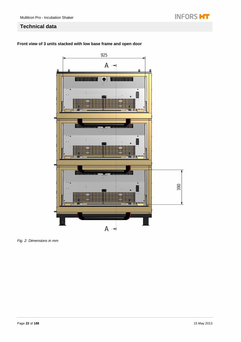
Front view of 3 units stacked with low base frame and open door
Fig. 2: Dimensions in mm

Multitron Pro - Incubation Shaker
Technical data
15 May 2013 Page 23 of 188
Side view of 3 units stacked with low base frame and closed door
Fig. 3: Dimensions in mm

Multitron Pro - Incubation Shaker
Technical data
Page 24 of 188 15 May 2013
Side view of 3 units stacked with low base frame and open door
Fig. 4: Dimensions in mm

Multitron Pro - Incubation Shaker
Technical data
15 May 2013 Page 25 of 188
Incubation chamber
Fig. 5 Dimensions in mm
Base unit
Description Value Unit
Width 1070 mm
Single unit height 520 mm
2-unit staple height 1040 mm
3-unit staple height 1560 mm
Base unit (with door handle) depth 880 mm
Base unit (with open door) depth 1160 mm
Base depth 715 mm
Incubation chamber
Description Value Unit
Width 925 mm
Depth 550 mm
Hight 387 mm
Hight with illumination inside 337 mm
Volumn ~200 L

Multitron Pro - Incubation Shaker
Technical data
Page 26 of 188 15 May 2013
Base frame
Description Value Unit
Rubber feet 30 mm
Trolley 90 mm
Frame low 130 mm
Frame high 310 mm
Cooling units
Description Value Unit
Side cooling width 245 mm
Top cooling width 1070 mm
Top cooling heigth 290 mm
Direct steam humidification
Description Value Unit
Direct steam humidification depth 80 mm
CO2 gassing
Description Value Unit
Width 30 mm
CO2 pressure reducing unit
Description Value Unit
Width 40 mm
ShakerBag gassing
Description Value Unit
Width 115 mm
Multitron Pro - Incubation Shaker
Technical data
15 May 2013 Page 27 of 188
Illumination daylight / photosynthesis Equivalent to base unit
Illumination algae
Description Value Unit
Illumination width 1260 mm
3.2 Weights
Base unit
Description Value Unit
Single unit 25mm throw 95 kg
Additional weight 50 mm throw 13 kg
1 units stacked 25mm throw 98 kg
2 units stacked 25mm throw 202 kg
3 units stacked 25mm throw 305 Kg
Approved load 25 throw (incl. tray)
Description Value Unit
Standard unit with 25 mm throw:
up to 350 rpm over 350 rpm
9 to 19 12 to 16
kg kg
Approved load 50 throw (incl. tray)
Description Value Unit
up to 250 rpm over 250 rpm
9 to 19 12 to 16
kg kg
Multitron Pro - Incubation Shaker
Technical data
Page 28 of 188 15 May 2013
M-tray
Description Value Unit
Tray 4.50 kg
Adhesive matting «Sticky Stuff» 0.50 kg
Clamp 25 mL 0.02 kg
Clamp 50 mL 0.02 kg
Clamp 100 mL 0.03 kg
Clamp 250 mL 0.06 kg
Clamp 500 mL 0.10 kg
Clamp 1000 mL 0.15 kg
Clamp 2000 mL 0.26 kg
Clamp 2800 mL (F3) 0.30 kg
Clamp 3000 mL 0.30 kg
Clamp 4000 mL 0.35 Kg
Clamp 5000 mL 0.45 Kg
Perforated tray
Description Value Unit
Perforated tray 3.5 kg
Base frame
Description Value Unit
Rubber feet 6 kg
Trolley 10 kg
Base frame 130 mm 26 kg
Base frame 310 mm 27 kg
Multitron Pro - Incubation Shaker
Technical data
15 May 2013 Page 29 of 188
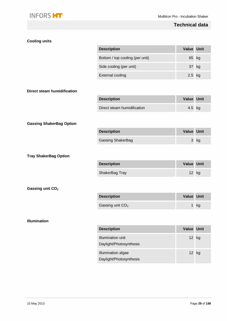
Cooling units
Description Value Unit
Bottom / top cooling (per unit) 65 kg
Side cooling (per unit) 37 kg
External cooling 2.5 kg
Direct steam humidification
Description Value Unit
Direct steam humidification 4.5 kg
Gassing ShakerBag Option
Description Value Unit
Gassing ShakerBag 3 kg
Tray ShakerBag Option
Description Value Unit
ShakerBag Tray 12 kg
Gassing unit CO2
Description Value Unit
Gassing unit CO2 1 kg
Illumination
Description Value Unit
Illumination unit Daylight/Photosynthesis
12 kg
Illumination algae Daylight/Photosynthesis
12 kg

Multitron Pro - Incubation Shaker
Technical data
Page 30 of 188 15 May 2013
3.3 Connection values
Electrical (single unit) Type 230V 50/60 Hz
Description Value Unit
Voltage 230 V
Power consumption max. 880 W
Power consumption stand-by 6 W
Current max. 3.8 A
Individual fusing 16 A
Frequency 50/60 Hz
2 unit fuses 5 x 20 mm, time-lag
10 A
Type 115V 60 Hz
Description Value Unit
Voltage 115 V
Power consumption max. 880 W
Power consumption stand-by 6 W
Current max. 7.7 A
Individual fusing 16 A
Frequency 60 Hz
2 unit fuses 5 x 20 mm, time-lag
16 A

Multitron Pro - Incubation Shaker
Technical data
15 May 2013 Page 31 of 188
Electrical Top cooling 900 Watts Type 230 V 50 Hz
Description Value Unit
Voltage 230 V
Power consumption max. 540 W
Current max. 4.2 A
Individual fuses 16 A
Frequency 50 Hz
2 unit fuses 5 x 20 mm, time-lag
10 A
Type 230 V / 60 Hz
Description Value Unit
Voltage 230 V
Power consumption max. 690 W
Current max. 4.6 A
Individual fuses 16 A
Frequency 60 Hz
2 unit fuses 5 x 20 mm, time-lag
10 A
Type 115 V / 60 Hz
Description Value Unit
Voltage 115 V
Power consumption max. 570 W
Current max. 7.5 A
Individual fuses 16 A
Frequency 60 Hz
2 unit fuses 5 x 20 mm, time-lag
16 A

Multitron Pro - Incubation Shaker
Technical data
Page 32 of 188 15 May 2013
Electrical Top cooling 1200 Watts Type 230 V 50 Hz
Description Value Unit
Voltage 230 V
Power consumption max. 650 W
Current max. 2.8 A
Individual fuses 16 A
Frequency 50 Hz
2 unit fuses 5 x 20 mm, time-lag
10 A
Type 230 V / 60 Hz
Description Value Unit
Voltage 230 V
Power consumption max. 800 W
Current max. 3.5 A
Individual fuses 16 A
Frequency 60 Hz
2 unit fuses 5 x 20 mm, time-lag
10 A
Type 115 V / 60 Hz
Description Value Unit
Voltage 115 V
Power consumption max. 800 W
Current max. 6.9 A
Individual fuses 16 A
Frequency 60 Hz
2 unit fuses 5 x 20 mm, time-lag
16 A

Multitron Pro - Incubation Shaker
Technical data
15 May 2013 Page 33 of 188
Electrical Side cooling 380 Watts Type 230 V 50 Hz
Description Value Unit
Voltage 230 V
Power consumption max. 220 W
Current max. 1.2 A
Fuses None
Frequency 50 Hz
2 unit fuses 5 x 20 mm, time-lag
10 A
Type 230 V / 60 Hz
Description Value Unit
Voltage 230 V
Power consumption max. 220 W
Current max. 1.2 A
Fuses None
Frequency 60 Hz
2 unit fuses 5 x 20 mm, time-lag
10 A
Type 115 V / 60 Hz
Description Value Unit
Voltage 115 V
Power consumption max. 200 W
Current max. 2.6 A
Fuses None
Frequency 60 Hz
2 unit fuses 5 x 20 mm, time-lag
16 A

Multitron Pro - Incubation Shaker
Technical data
Page 34 of 188 15 May 2013
Electrical Direct steam humidification Type 230V 50/60 Hz
Description Value Unit
Power consumption, max. 125 W
Current 0.4 A
Type 115V 60 Hz
Description Value Unit
Power consumption, max. 125 W
Current 0.9 A
Electrical Heated door
Description Value Unit
Voltage 24 V
Power consumption 18.8 W
Current 0.8 A
Electrical CO2 Gassing
Description Value Unit
Power consumption 4.5 W

Multitron Pro - Incubation Shaker
Technical data
15 May 2013 Page 35 of 188
Electrical Gassing ShakerBag Option Type 230V 50/60 Hz
Description Value Unit
Electrical Power 25 W
Power consumption max. 0.1 A
Type 115V 50/60 Hz
Description Value Unit
Electrical Power 25 W
Power consumption max. 0.2 A
Electrical Illumination daylight / photosynthesis Type 230V 50/60 Hz
Description Value Unit
Voltage 230 V
Power consumption 180 W
Current 0.8 A
Type 115V 60 Hz
Description Value Unit
Voltage 115 V
Power consumption 180 W
Current 1.6 A

Multitron Pro - Incubation Shaker
Technical data
Page 36 of 188 15 May 2013
Electrical Illumination algae daylight / photosynthesis Type 230V 50/60 Hz
Description Value Unit
Voltage 230 V
Power consumption 250 W
Current 1.1 A
Type 115V 60 Hz
Description Value Unit
Voltage 115 V
Power consumption 250 W
Current 2.2 A
Electrical Mobile Pt100 sensor
Description Value Unit
Voltage 24 V
Electrical UV-sterilisation
Description Value Unit
Power consumption 11 W

Multitron Pro - Incubation Shaker
Technical data
15 May 2013 Page 37 of 188
3.4 Specifications
General information
Description Value
Material housing PU, safety glass
Material chamber Stainless steal
Material table Aluminum, anodized
Mounting table 4 x M5x16, hexagon socket
Fuses
230 V, 50/60 Hz 2 x 20 mm 10 Amperes time-lag
115 V, 60 Hz 2 x 20 mm 16 Amperes time-lag
Hose nozzle
Ø inner diameter nozzle
8 mm
Ø inner diameter hose
10 mm
Temperature
Description Value
Power 2 cross flow blowers with heating
700 W
Air circulation 360 m3/h
Control Electronic PID-controller
Sensor Pt100
Operating range +4 °C up to +80 °C, typically up to 65 °C
Control accuracy ± 0.2 °C
Measuring accuracy ± 0.15 °C
Control accuracy capillary thermostat
± 2.5 °C
Capillary thermostat Adjustable, standard setting ex works 70 °C
Multitron Pro - Incubation Shaker
Technical data
Page 38 of 188 15 May 2013
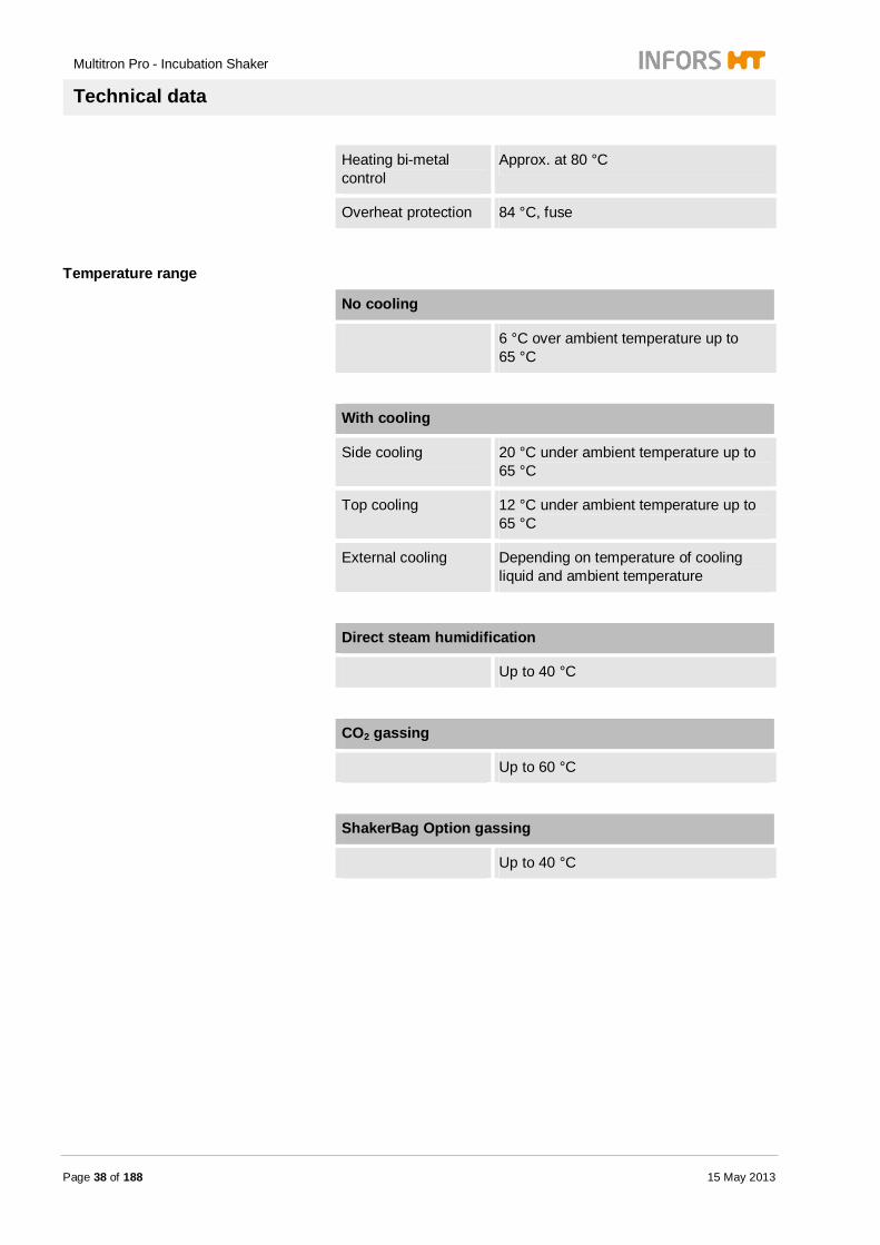
Heating bi-metal control
Approx. at 80 °C
Overheat protection 84 °C, fuse
Temperature range
No cooling
6 °C over ambient temperature up to 65 °C
With cooling
Side cooling 20 °C under ambient temperature up to 65 °C
Top cooling 12 °C under ambient temperature up to 65 °C
External cooling Depending on temperature of cooling liquid and ambient temperature
Direct steam humidification
Up to 40 °C
CO2 gassing
Up to 60 °C
ShakerBag Option gassing
Up to 40 °C
Multitron Pro - Incubation Shaker
Technical data
15 May 2013 Page 39 of 188
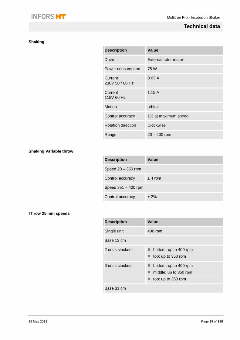
Shaking
Description Value
Drive External rotor motor
Power consumption 75 W
Current 230V 50 / 60 Hz
0.63 A
Current 115V 60 Hz
1.15 A
Motion orbital
Control accuracy 1% at maximum speed
Rotation direction Clockwise
Range 20 – 400 rpm
Shaking Variable throw
Description Value
Speed 20 – 350 rpm
Control accuracy ± 4 rpm
Speed 351 – 400 rpm
Control accuracy ± 2%
Throw 25 mm speeds
Description Value
Single unit 400 rpm
Base 13 cm
2 units stacked bottom: up to 400 rpm top: up to 350 rpm
3 units stacked bottom: up to 400 rpm middle: up to 350 rpm top: up to 350 rpm
Base 31 cm
Multitron Pro - Incubation Shaker
Technical data
Page 40 of 188 15 May 2013
2 units stacked bottom: up to 400 rpm top: up to 250 rpm
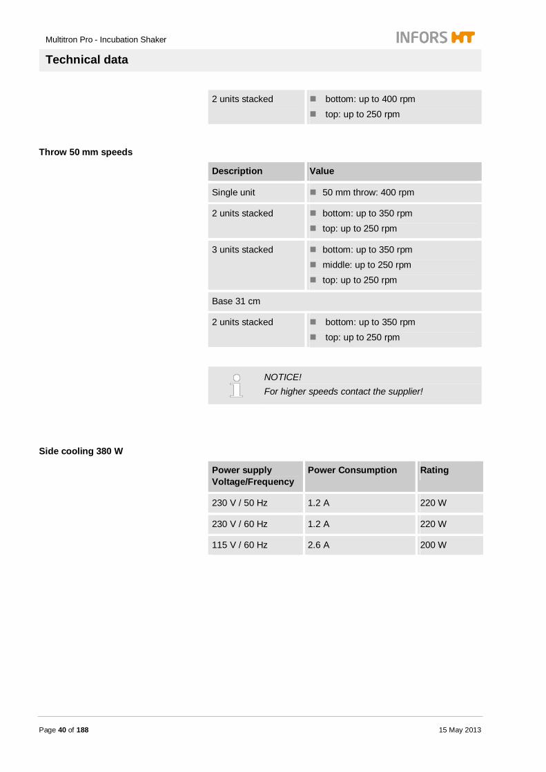
Throw 50 mm speeds
Description Value
Single unit 50 mm throw: 400 rpm
2 units stacked bottom: up to 350 rpm top: up to 250 rpm
3 units stacked bottom: up to 350 rpm middle: up to 250 rpm top: up to 250 rpm
Base 31 cm
2 units stacked bottom: up to 350 rpm top: up to 250 rpm
NOTICE! For higher speeds contact the supplier!
Side cooling 380 W
Power supply Voltage/Frequency
Power Consumption Rating
230 V / 50 Hz 1.2 A 220 W
230 V / 60 Hz 1.2 A 220 W
115 V / 60 Hz 2.6 A 200 W
Multitron Pro - Incubation Shaker
Technical data
15 May 2013 Page 41 of 188
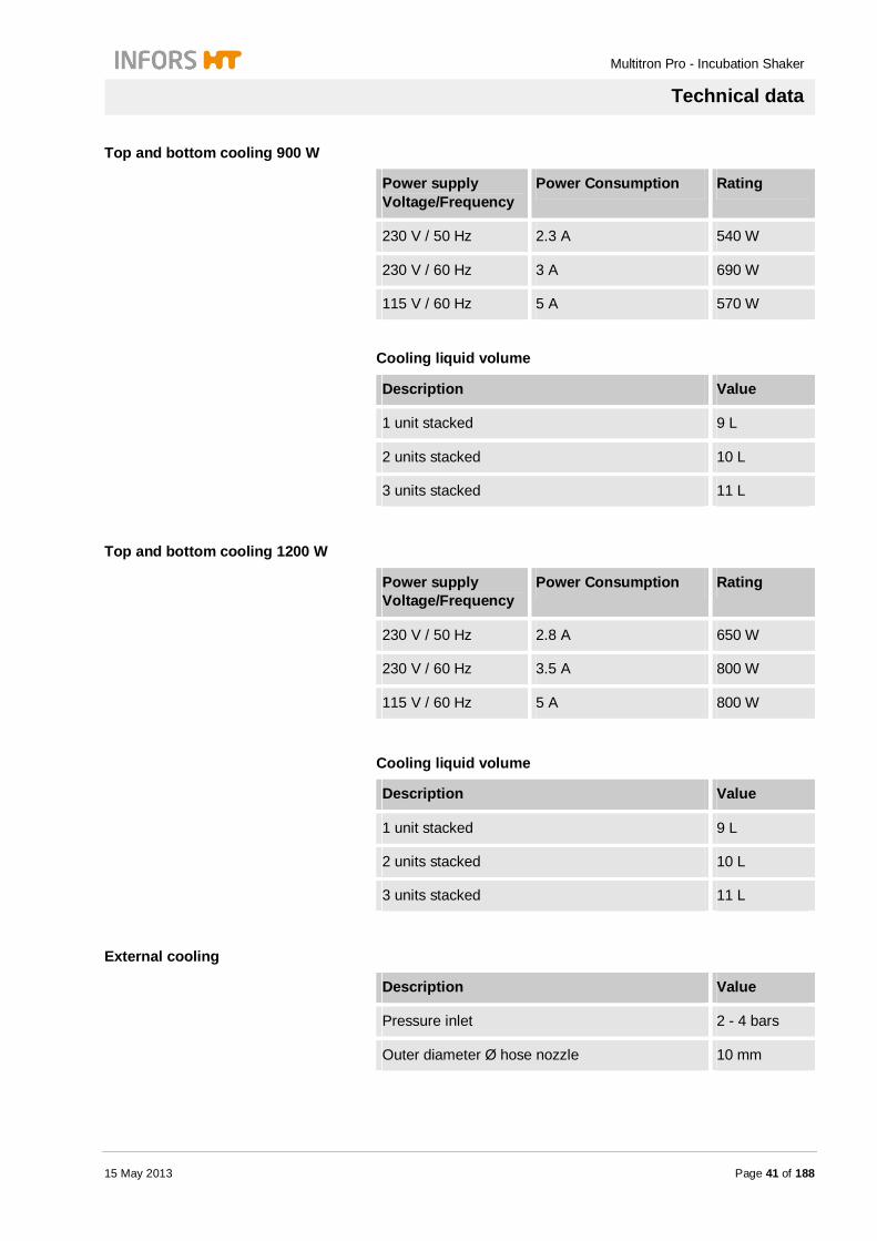
Top and bottom cooling 900 W
Power supply Voltage/Frequency
Power Consumption Rating
230 V / 50 Hz 2.3 A 540 W
230 V / 60 Hz 3 A 690 W
115 V / 60 Hz 5 A 570 W
Cooling liquid volume
Description Value
1 unit stacked 9 L
2 units stacked 10 L
3 units stacked 11 L
Top and bottom cooling 1200 W
Power supply Voltage/Frequency
Power Consumption Rating
230 V / 50 Hz 2.8 A 650 W
230 V / 60 Hz 3.5 A 800 W
115 V / 60 Hz 5 A 800 W
Cooling liquid volume
Description Value
1 unit stacked 9 L
2 units stacked 10 L
3 units stacked 11 L
External cooling
Description Value
Pressure inlet 2 - 4 bars
Outer diameter Ø hose nozzle 10 mm

Multitron Pro - Incubation Shaker
Technical data
Page 42 of 188 15 May 2013
Adhesive matting «Sticky Stuff» For operating the adhesive matting «Sticky Stuff» only high quality flasks with flat-bottom are allowed.
Following materials are permitted: Borosilicate glass (3.3) – flasks, e.g. Schott Duran® glass
Polycarbonate – flasks, e.g. Corning® The use of all other materials or quality levels is in the responsibility of the user.
CAUTION! Danger of damage of property by released or broken flasks when using inapplicable flasks. Flasks of bad quality or deficient contact surface may be accidentally released from the adhesive matting when shaking or may break at removing process. Therefore: – Use only recommended flasks – Use only flasks that are intact and free of
scratches
NOTICE! The following speed values are only valid for flasks with 20% filling level. Adhesive matting and flasks have to be totally intact, dry and fat-free.

Multitron Pro - Incubation Shaker
Technical data
15 May 2013 Page 43 of 188
Type 50 mm throws
Description Value
Temperature range 16 – 60 °C
Size 200 x 200 mm
Max. rotations Erlenmeyer flasks Borosilicate glass (3.3)
25 – 750 mL: 200 rpm
1000 mL: 250 rpm
2000 mL: 250 rpm
3000 mL: 300 rpm
5000 mL: 250 rpm
Max. rotations Erlenmeyer flasks Polycarbonate
125 – 3000 mL: 200 rpm
Max. rotations Fernbach flasks Polycarbonate
3000 mL: 250 rpm
Type 25 mm throws
Description Value
Temperature range 16 – 60 °C
Size 200 x 200 mm
Max. rotations Erlenmeyer flasks Borosilicate glass (3.3)
25 – 750 mL: 250 rpm
1000 mL: 300 rpm
2000 mL: 300 rpm
3000 mL: 350 rpm
5000 mL: 300 rpm
Max. rotations Erlenmeyer flasks Polycarbonate
125 – 3000 mL: 250 rpm
Max. rotations Fernbach flasks Polycarbonate
3000 mL: 300 rpm

Multitron Pro - Incubation Shaker
Technical data
Page 44 of 188 15 May 2013
Direct steam humidification
Description Value
Inlet pressure Max. 0.3 bars
Supply constant
Hose nozzle 8 mm
Control range 20 – 85% rH
Accuracy ± 0.3% rH at 20 °C and 54% rH
Measuring method capacitive
Control method Inlet valve
Hose 8 mm Legris-connection
Water consumption reference value
10 g/h at 37 °C, 80% rH per unit
Water quality Hardness < 0.01 mmol/L CaCO3, equivalent
Conductivity < 20 µS/cm
Dissolved solids < 10 mg/L
Approachable values of humidity
Temperature Maximum humidity
27 °C 85 %rH
33 °C 85 %rH
37 °C 85 %rH
Path through
Description Value
Unit Roxtec EzEntry 4 Mini
Diameter pass through
4 x 3.5 – 16.5 mm
Torque screws
3 – 5 Nm
Multitron Pro - Incubation Shaker
Technical data
15 May 2013 Page 45 of 188
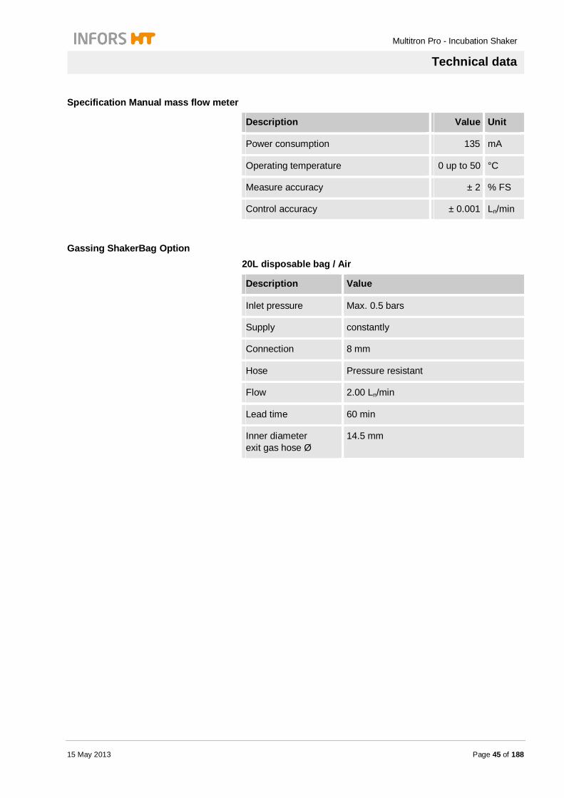
Specification Manual mass flow meter
Description Value Unit
Power consumption 135 mA
Operating temperature 0 up to 50 °C
Measure accuracy ± 2 % FS
Control accuracy ± 0.001 Ln/min
Gassing ShakerBag Option 20L disposable bag / Air
Description Value
Inlet pressure Max. 0.5 bars
Supply constantly
Connection 8 mm
Hose Pressure resistant
Flow 2.00 Ln/min
Lead time 60 min
Inner diameter exit gas hose Ø
14.5 mm
Multitron Pro - Incubation Shaker
Technical data
Page 46 of 188 15 May 2013
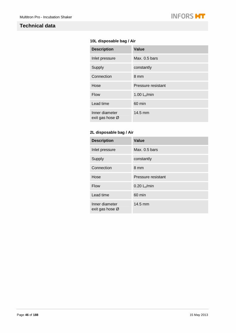
10L disposable bag / Air
Description Value
Inlet pressure Max. 0.5 bars
Supply constantly
Connection 8 mm
Hose Pressure resistant
Flow 1.00 Ln/min
Lead time 60 min
Inner diameter exit gas hose Ø
14.5 mm
2L disposable bag / Air
Description Value
Inlet pressure Max. 0.5 bars
Supply constantly
Connection 8 mm
Hose Pressure resistant
Flow 0.20 Ln/min
Lead time 60 min
Inner diameter exit gas hose Ø
14.5 mm

Multitron Pro - Incubation Shaker
Technical data
15 May 2013 Page 47 of 188
ShakerBag Tray
Description Value
Tray capacity for disposable bags
3 x 2 L 2 x 10 L
1 x 20 L
Heat resistance Up to 65 °C
Cleaning Mild detergent
Disinfection Standard disinfectants
Sterilisation Not possible
CO2 gassing Gassing unit
Description Value
Inlet pressure Maximum 0.5 bars
Supply constantly
Flow (clocked) 120 – 480 NL/h (rotameter recommended)
Consumption Approx. 13L/h (reference value)
Warm-up period 15 min
Temperature range Up to 60 °C
Humidity range 0 – 100% rH not condensing
Connection inner diameter hose
6 mm
Hose Pressure resistant
Measuring range 0 – 20% CO2
Control range 0 – 19.5% CO2
Response time 20 s
Measuring method Infrared
Control method Inlet valve

Multitron Pro - Incubation Shaker
Technical data
Page 48 of 188 15 May 2013
Accuracy at 25 °C ± 0.02% CO2 + 2% FS
Dependency temperature
0.1% FS/°C
Dependency pressure 0.1% FS/mbars
Long-term stability < ± 5% FS/2 years
CO2 curtain
Description Value
Material PVC, UV-stabilized
Heat resistance Up to 65 °C
CO2 pressure reducing unit
Description Value
Inlet pressure max. 20 bars
Supply constant
Rotameter Flow 1 – 6,7 NL/min
Accuracy ± 4% FS
Loss of pressure max.
20 mbar
Gassing tube
Description Value
Outer diameter Ø 10 mm
Length 330 mm
Control none

Multitron Pro - Incubation Shaker
Technical data
15 May 2013 Page 49 of 188
Illumination Daylight
Fig. 6
Description Value
Fluorescent lamp T8 socket G13 15 Watts
Color temperature 4000 K
Life cycle 9000 h
Starter single connection (115V / 230V) Life cycle 8000h
FS 22
Length 438 mm
Photosynthesis
Fig. 7
Description Value
Fluorescent lamp T8 socket G13 15 Watts
Color temperature 8500 K
Life cycle 9000 h
Starter single connection (115V / 230V) Life cycle 8000h
FS 22
Length 438 mm
Illumination algae Daylight
Fig. 8
Description Value
Fluorescent lamp L 36/77 socket G13 36 Watts
Luminous flux at 25 °C 1400 lm
Length 1200 mm
Life cycle 13.000 h

Multitron Pro - Incubation Shaker
Technical data
Page 50 of 188 15 May 2013
Mobile Pt100-Sensor
Description Value
Control Electronic PID-Controller
Sensor Pt100
Control accuracy 0.2 °C
Measure accuracy 0.15 °C
UV-sterilization of process air
Abb. 9
Description Value
UV-sterilization lamp 5 Watts socket G23 5 Watts
Wave length UV-C 200 – 280 nm
Maximum emission 253.7 nm
Life cycle 9000 h
Output UV-C radiation 1.1 Watts
Intensity after 5000 h 80%
Output total 11 Watts
Power consumption total 0.18 A
3.5 Operating conditions
Description Value
Ambient temperature max.
With / without cooling 30 °C
Ambient temperature max.
without cooling: 8 °C below required minimum incubation temperature
with cooling: side cooling: 15 °C top cooling: 12 °C upon required minimum incubation temperature
Relative humidity max.
With / without cooling: 85% rH

Multitron Pro - Incubation Shaker
Technical data
15 May 2013 Page 51 of 188
3.6 Emissions
Description Value Unit
Noise emission <70 dB(A)
3.7 Utilities
CAUTION! Risk of loss of property due using of inappropriate utilities! Using wrong utilities may cause loss of property. Therefore: – Only use manufacturer prescribed utilities, listed
in the following table.
Description Valid substances
Cooling liquid Secondary circuit
Top cooling External cooling
Permitted for food and pharmaceutical fields Freezing < -40 °C Corrosion copper: < -0.6 g/m2
Temperature range: -40 °C up to 150 °C
Water quality direct steam humidification
Distilled water Deionized water Demineralized water
Reverse-osmosis water (for details see appendix)
Cleaning agents generally Mild cleaning agents
Disinfectants generally Quaternary ammonium compounds
Disinfectants door pane polycarbonate
Quaternary ammonium compounds
Cleaning agents adhesive matting
Mild cleaning agents
Disinfectants adhesive matting
Quaternary ammonium compounds

Multitron Pro - Incubation Shaker
Technical data
Page 52 of 188 15 May 2013
3.8 Identification plate Es beinh altet f olge nde An gab en:
Fig. 10
The identification plate is placed in the middle of the front side underneath the front door.
It contains the following information:
Fig. 11
Name and internet address of the manufacturer TYPE = Model Type NR = Serial number VOLT = Nominal voltage
AMP = Current consumption YEAR = Year of manufacture
CE-marking
3.9 Interface communication protocol For communication with other equipment a serial interface is available.
The communication protocol can be ordered via [email protected].
Multitron Pro - Incubation Shaker
Setup and function
15 May 2013 Page 53 of 188
4 Setup and function
Options of Equipment
NOTICE! All optional features or optional components of the equipment are not part of the delivery of the standard machine!
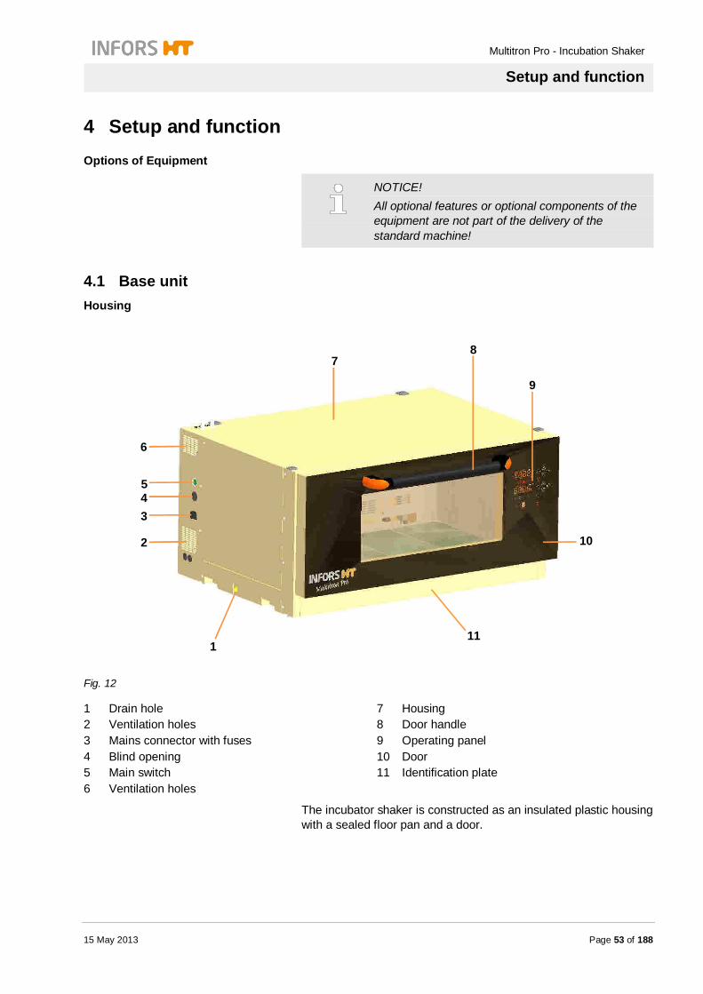
4.1 Base unit Housing
Fig. 12
1 Drain hole 2 Ventilation holes 3 Mains connector with fuses 4 Blind opening 5 Main switch 6 Ventilation holes
7 Housing 8 Door handle 9 Operating panel 10 Door 11 Identification plate
The incubator shaker is constructed as an insulated plastic housing with a sealed floor pan and a door.
1
2
3 4 5
6
7 8
9
10
11
Multitron Pro - Incubation Shaker
Setup and function
Page 54 of 188 15 May 2013
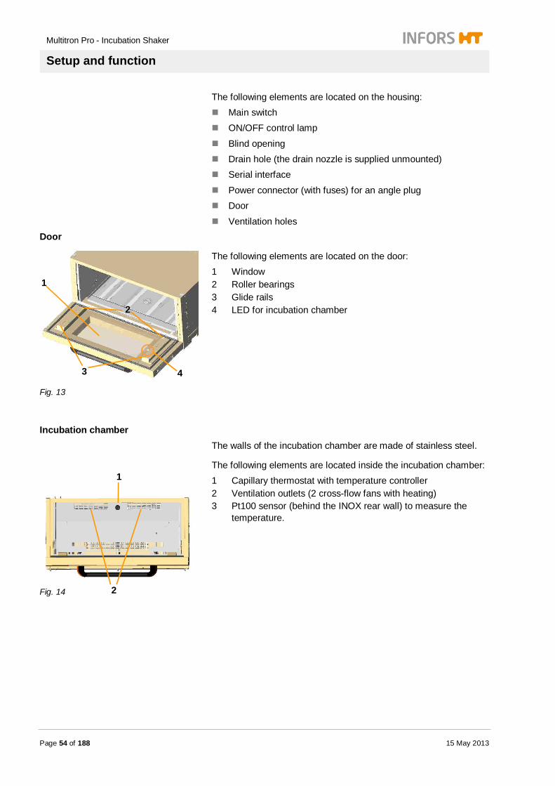
The following elements are located on the housing: Main switch ON/OFF control lamp
Blind opening Drain hole (the drain nozzle is supplied unmounted) Serial interface
Power connector (with fuses) for an angle plug Door
Ventilation holes Door
Fig. 13
The following elements are located on the door: 1 Window 2 Roller bearings 3 Glide rails 4 LED for incubation chamber
Incubation chamber
The walls of the incubation chamber are made of stainless steel.
Fig. 14
The following elements are located inside the incubation chamber: 1 Capillary thermostat with temperature controller 2 Ventilation outlets (2 cross-flow fans with heating) 3 Pt100 sensor (behind the INOX rear wall) to measure the
temperature.
1
2
3
1
2
4

Multitron Pro - Incubation Shaker
Setup and function
15 May 2013 Page 55 of 188
There is a safety fuse located between the cross-flow fans behind the rear wall. It protects against overheating.
Fig. 15
1 Table 2 Cones (to lock the tray) 3 Stop bar
Fig. 16
1 Rear stops 2 Guide rails
Fig. 17
Locking hooks
2
1
2
1 3
Multitron Pro - Incubation Shaker
Setup and function
Page 56 of 188 15 May 2013
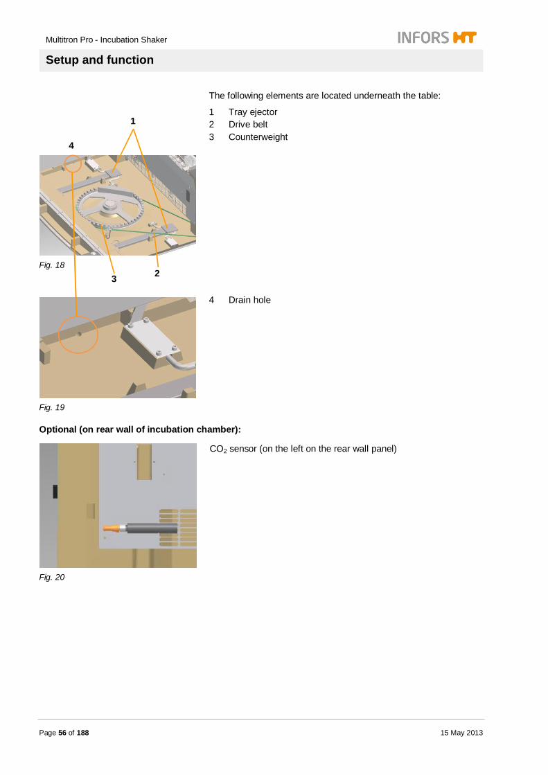
The following elements are located underneath the table:
Fig. 18
1 Tray ejector 2 Drive belt 3 Counterweight
Fig. 19
4 Drain hole
Optional (on rear wall of incubation chamber):
Fig. 20
CO2 sensor (on the left on the rear wall panel)
1
4
2 3

Multitron Pro - Incubation Shaker
Setup and function
15 May 2013 Page 57 of 188
Fig. 21
Humidity sensor (on the right on the rear wall panel)
Fig. 22
Mobile Pt100 sensor
G
Transport lock
Fig. 23
The table and the counterweight are secured with a star knob screw during transport to stop them moving uncontrollably.
This lock is located in the front section of the table.

Multitron Pro - Incubation Shaker
Setup and function
Page 58 of 188 15 May 2013
NOTICE! Please keep the star knob screw in a safe place for future use. Do not relocate the unit without engaging the transport lock first.
4.2 Basic Functions Shaking
The table rotates with a speed of 20 to 400 RPM. The counterbalancing weight is located underneath the table. Depending on the model (fixed throw or variable throw), the orbital throw is 12.5 mm, 25 mm or 50 mm.
The loading weights must lie within the specified range. Loading weights above or below this range prevent the table moving smoothly and thus increase wear of the bearings and joints.
The loading weights depend on the position of the deck in the stack, the throw and the rotation speed.
NOTICE! The loading weights and maximum speeds are given in the chapter "Technical Data".
Temperature control
The temperature is controlled via two cross-flow fans, which are each equipped with a downstream heating element. The temperature is measured and controlled with a Pt100 temperature sensor. The two cross-flow fans are each equipped with a thermostat to prevent overheating. It switches off the heating at 80 °C.
The incubation shaker is doubly protected against overheating: Capillary thermostat with rotary knob
(standard setting from 65 °C) Melting fuse (84 °C)
NOTICE! Please contact the manufacturer's service center if the melting fuse has blown. The heating is out of order and can only be reinstated by replacing the melting fuse.

Multitron Pro - Incubation Shaker
Setup and function
15 May 2013 Page 59 of 188
Control system The incubator shaker is equipped with a microprocessor control system. It is used to control, monitor and program the unit. Each deck of a stack can be operated from each operating panel. An integrated timer function allows programming of time cycles. Various displays and alarm functions are integrated into the control system.
Operation The operating panel in the door of the incubator shaker is used to activate the parameters and set the target values. The incubator shaker is equipped with a tray lock that secures the tray to the table. When the door is fully open, the locking hooks on the table release the tray. The tray ejectors underneath the table lift the tray out of the locking cones on the table. The tray is pulled out of the incubation chamber over glide rails and the embedded roller bearings located on the interior side of the door. 2 Cylindrical pins (stops) in the glide rails limit the end position of the extended tray. The fully extended tray rests partly on the door and partly on the table.
The table is stopped as soon as the door is opened by more than 30°. The door can only be opened completely after the table has stopped moving. The table restarts automatically as soon as the door is closed by more than 45°. All activated parameters are stopped as soon as the door is opened by more than 30°. They are re-activated as soon as the door is closed by more than 45°.
4.3 Messages An alarm system is integrated into the unit to monitor its functions.
The incubation shaker differentiates between: Alarm:
Setpoint value not reached (usually due to an operating error) Display: High, Low, RESTARTED, warning symbol
and Error messages:
Fault due to a defect component or blocked table Display: ERROR, Er1, Er2, warning symbol
NOTICE! For evaluation and troubleshooting of interferences: please refer to Chapter 9 Interferences.

Multitron Pro - Incubation Shaker
Setup and function
Page 60 of 188 15 May 2013
An alarm is triggered when a parameter does not reach the setpoint value within defined time.
The alarm is automatically cancelled when the parameter reaches the setpoint value.
There are three ways of issuing an alarm: visually acoustically
analog signal
Visual alarm
Value below setpoint: Low
Value above setpoint: High
Restart after power failure
Acoustic alarm
PIEP – PIEP – PAUSE – PIEP – PIEP
An error message is triggered when the incubation shaker ha a fault. This is the case when a component is defect or communication between sensor and control is interrupted.
Visual error message
The displays show various error messages. Please refer to chapter Interferences.
Message ERROR lights and warning symbol blinks.
Acoustic error message
PIEP – PAUSE – PIEP
Multitron Pro - Incubation Shaker
Setup and function
15 May 2013 Page 61 of 188
Warning symbol
The warning symbol lights at any operations. Additionally it lights when as alarm or error is triggered. The warning symbol supports the user to operate the incubation shaker properly.
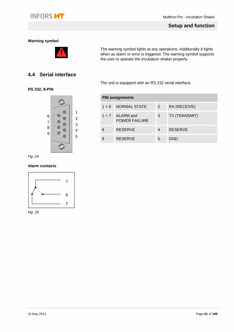
4.4 Serial interface The unit is equipped with an RS 232 serial interface.
RS 232, 9-PIN
Fig. 24
PIN assignments
1 + 6 NORMAL STATE 2 RX (RECEIVE)
1 + 7 ALARM and POWER FAILURE
3 TX (TRANSMIT)
8 RESERVE 4 RESERVE
9 RESERVE 5 GND
Alarm contacts
Fig. 25
1 2 3 4 5
6 7 8 9

Multitron Pro - Incubation Shaker
Setup and function
Page 62 of 188 15 May 2013
4.5 Option Analog Interface The unit is equipped with an analog interface DB 15.
DB 15, female, 15-PIN
Fig. 26
PIN assignments
15 GND 8 RESERVE
14 GND 7 RESERVE
13 GND 6 RESERVE
12 GND 5 RESERVE
11 GND 4 CO2 0 – 10%
10 GND 3 HUMIDITY 0 – 100%
9 GND 2 TEMP 0 – 100 °C
1 RPM 0 – 500 RPM
Signal strength 0 – 10V

Multitron Pro - Incubation Shaker
Setup and function
15 May 2013 Page 63 of 188
4.6 Option bases The incubator shaker can be equipped with the following bases:
Fig. 27
Rubber feet, 3 cm (bench-top model, standard)
Fig. 28
Trolley, base frame 13 cm plus castors (optional)
Fig. 29
Base frame, 13 cm (optional)
Fig. 30
Base frame, 31 cm (optional)
Multitron Pro - Incubation Shaker
Setup and function
Page 64 of 188 15 May 2013
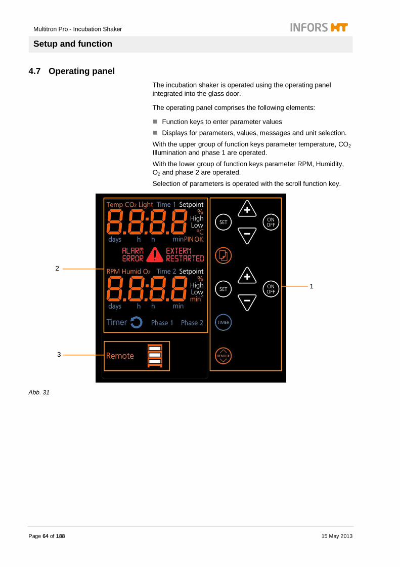
4.7 Operating panel The incubation shaker is operated using the operating panel integrated into the glass door.
The operating panel comprises the following elements:
Function keys to enter parameter values Displays for parameters, values, messages and unit selection.
With the upper group of function keys parameter temperature, CO2 Illumination and phase 1 are operated.
With the lower group of function keys parameter RPM, Humidity, O2 and phase 2 are operated.
Selection of parameters is operated with the scroll function key.
Abb. 31
1
2
3

Multitron Pro - Incubation Shaker
Setup and function
15 May 2013 Page 65 of 188
1 Function keys to enter parameter values. 2 Displays parameter, timer and messages.
Displays parameter values, parameters and units. Diplays messages
Displays timer functions Diplays Setpoint, High, Low
3 Display unit selection and remote access.
Parameter symbols and units lit orange when active. Values and messages in the displays lit orange when active. Warning symbol and warning messages lit red when active. Function of timer lit blue when active.
Setpoint, High and Low lit white when active.
Multitron Pro - Incubation Shaker
Setup and function
Page 66 of 188 15 May 2013
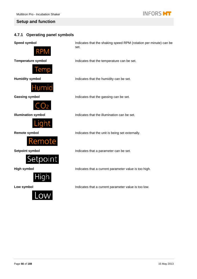
4.7.1 Operating panel symbols
Speed symbol
Indicates that the shaking speed RPM (rotation per minute) can be set.
Temperature symbol
Indicates that the temperature can be set.
Humidity symbol
Indicates that the humidity can be set.
Gassing symbol
Indicates that the gassing can be set.
Illumination symbol
Indicates that the illumination can be set.
Remote symbol
Indicates that the unit is being set externally.
Setpoint symbol
Indicates that a parameter can be set.
High symbol
Indicates that a current parameter value is too high.
Low symbol
Indicates that a current parameter value is too low.

Multitron Pro - Incubation Shaker
Setup and function
15 May 2013 Page 67 of 188
Timer symbol
Indicates that timer function can be operated (duration of Time1 and Time 2).
Cycle symbol
Indicates, that both timer are active.
Phase 1 symbol
Indicates, that the equipment is operating in timephase 1.
Phase 2 symbol
Indicates, that the equipment is operating in timephase 2.
Time 1 symbol
Indicates, that programming mode of timer is active and Time 1 is selected.
Time 2 symbol
Indicates, that programming mode of timer is active and Time 2 is selected.
EXTERN symbol
Indicates, that the equipment is accessed by remote.
RESTARTED symbol
Indicates, that the equipment had a power supply interruption.
ALARM symbol
Indicates, that a current value of a parameter is in the alarm limits.
ERROR symbol
Indicates, that an interference occurred.
WARNING symbol
Indicates, that the equipment is in a special mode except the normal operating mode.
Multitron Pro - Incubation Shaker
Setup and function
Page 68 of 188 15 May 2013
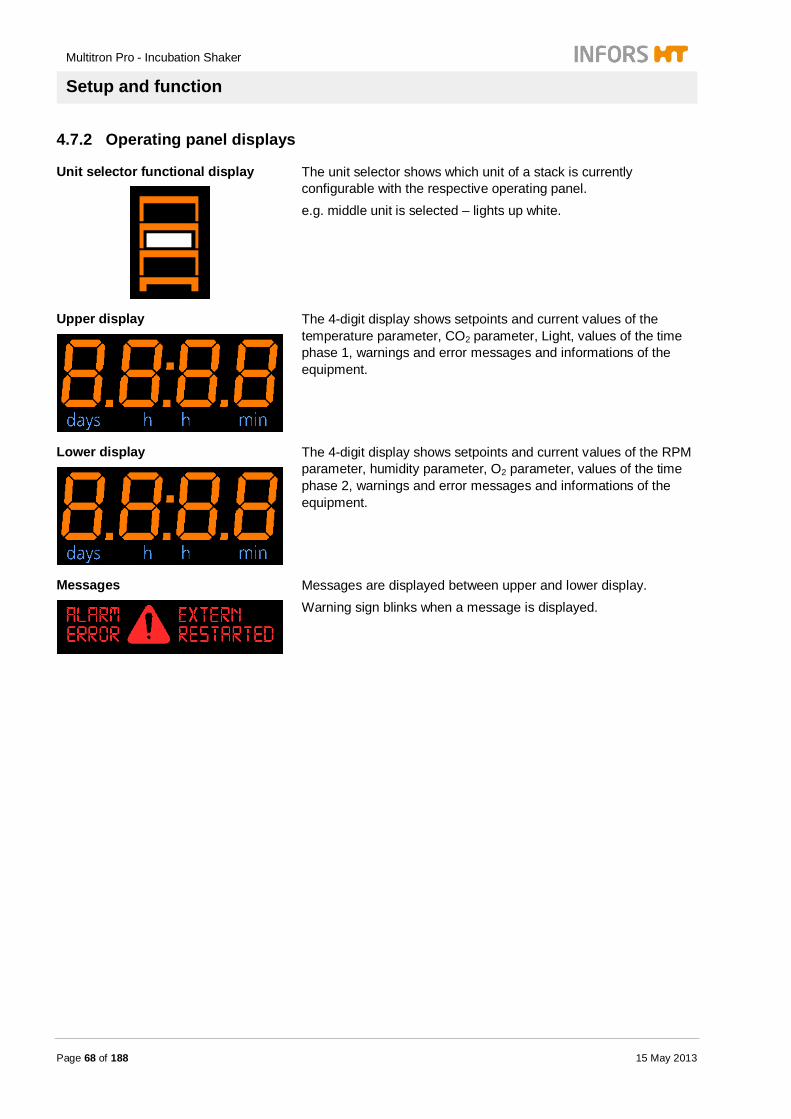
4.7.2 Operating panel displays
Unit selector functional display
The unit selector shows which unit of a stack is currently configurable with the respective operating panel. e.g. middle unit is selected – lights up white.
Upper display
The 4-digit display shows setpoints and current values of the temperature parameter, CO2 parameter, Light, values of the time phase 1, warnings and error messages and informations of the equipment.
Lower display
The 4-digit display shows setpoints and current values of the RPM parameter, humidity parameter, O2 parameter, values of the time phase 2, warnings and error messages and informations of the equipment.
Messages
Messages are displayed between upper and lower display. Warning sign blinks when a message is displayed.

Multitron Pro - Incubation Shaker
Setup and function
15 May 2013 Page 69 of 188
4.7.3 Operating panel keys
ON/OFF function key
Switches parameters and timer on or off.
SET function key
Activates the edit mode of parameters or timer.
Option function key
Scrolls through the installed parameters.
PLUS function key
Increases the value of the selected parameter or time phase.
MINUS function key
Decreases the value of the selected parameter or time phase.
TIMER function key
Activates the edit mode of the timer.
REMOTE function key
Switches between the controls systems of the individual units in stacked systems.

Multitron Pro - Incubation Shaker
Setup and function
Page 70 of 188 15 May 2013
4.8 Option cooling system The incubator shaker is equipped with a cooling system so that cultivation can be carried out in a defined climate. The heat exchanger of all cooling systems is located behind the rear wall of the incubation chamber. The following cooling systems are available:
Top-mounted cooling system, 900 watts / 1200 watts
Fig. 32
The cooling unit is located in a housing mounted on top of the incubator shaker.
It can cool up to three incubators. The cooling unit has a separate power supply.
The mains switch is located on the left-hand side of the mounted housing.
The cooling unit has a twin-circuit system with a coolant tank. The coolant tank is located in the mounted housing.
Side-mounted cooling system, 380 watts
Fig. 33
The cooling unit is located in a housing mounted on the side of the incubator shaker.
It can cool only one incubator. The incubator shaker supplies power to the cooling unit.
The cooling unit is a closed single-circuit system.

Multitron Pro - Incubation Shaker
Setup and function
15 May 2013 Page 71 of 188
External cooling system
CAUTION! Risk of material damage to the circulating pump of the external cooling unit. The circulating pump of the external coolant system may be damaged if it is not connected correctly. Therefore: – The cooling register must be connected to the
external coolant system with a bypass.
Fig. 34
The cooling unit is supplied with cooling liquid from the in-house cooling system.
A control valve opens when necessary to allow coolant to flow through the cooling register.
The inlet and outlet of the coolant circuit are each equipped with a male hose nozzle with an outside diameter of 10 mm.
They are located on the upper left-hand side of the top of the incubator shaker.
The cooling unit does not require a power supply.

Multitron Pro - Incubation Shaker
Setup and function
Page 72 of 188 15 May 2013
4.9 Option «Sticky Stuff» adhesive matting
Fig. 35
The «Sticky Stuff» adhesive matting is a very sticky mat that lines the tray. It can be detached from the tray and replaced. The adhesive matting can also be used on perforated trays.
The adhesive matting provides secure purchase for cultivation flasks with a large base.
The tray is labeled on two diagonally opposed corners with an information sticker on how to remove the cultivation flasks.
These stickers must not be removed under any circumstances.
4.10 Option Direct Steam Humidification The incubator shaker is equipped with a Direct Steam Humidification. The Direct Steam Humidification is switched on or off via the operating panel. A humidity sensor, located on the rear wall of the incubation chamber, measures the humidity.
Please note the following points:
The Direct Steam Humidification operates in one direction only. It increases the humidity, but does not decrease it.
The Direct Steam Humidification only operates correctly at temperatures up to 40 °C.
The temperature parameter must be switched on.
The cooling system switches off automatically when the Direct Steam Humidification is switched on.

Multitron Pro - Incubation Shaker
Setup and function
15 May 2013 Page 73 of 188
NOTICE! An optional control program is available for simultaneous operation of the humidification and the cooling system.
If the illumination is switched on, the maximum humidity may
not reach 85% rH under all conditions.
Fig. 36
The Direct Steam Humidification is mounted on the rear of the housing.
A controlled pump feeds water dropwise into an evaporator chamber via a feed hose. The steam is then fed directly into the incubation chamber.
There are two types of water supply: unpressurised from a water tank
pressurised to max. 0.3 bars from a pressurised pipeline
4.11 Option CO2 gassing The incubator shaker is equipped with a CO2 gassing unit.
This comprises: A controlled CO2 gassing device A transparent safety curtain inside the chamber (the gassing
unit can be operated without the curtain fitted)

Multitron Pro - Incubation Shaker
Setup and function
Page 74 of 188 15 May 2013
Controlled CO2 gassing device
Fig. 37
The inlet nozzle is located on the right-hand wall of the housing. The CO2 supply is provided with a control valve. There is a CO2 sensor inside the chamber that transmits the measured CO2 content to the control unit. The CO2 gassing unit is operated via the operating panel.
Transparent safety curtain
Fig. 38
1 PVC safety curtain 2 Circulation holes for humidification(optional) 3 Snap fasteners 4 Marking
Fig. 39
Snap fastener
4
1 2
3
Multitron Pro - Incubation Shaker
Setup and function
15 May 2013 Page 75 of 188
Fig. 40
Label "outside"
The curtain is made of transparent PVC sheeting, 0.75 mm thick. There are four snap fasteners on the upper front edge of the incubation chamber to attach the curtain. The lower edge of the curtain has 8 slits to facilitate handling of the tray. The curtain is marked "outside" so that it can be fitted correctly. The transparent curtain is attached to the upper front edge of the housing by means of the 4 snap fasteners. The curtain prevents large amounts of CO2 escaping when the door is opened.
NOTICE!
The safety curtain keeps the CO2 gas inside the incubation chamber:
approx. 60% on opening the door approx. 40% on pulling out the tray
There are two types of safety curtain:
Fig. 41
CO2 – closed
Fig. 42
CO2 + humidification – with 8 circular holes (Ø 45 mm) in the upper section

Multitron Pro - Incubation Shaker
Setup and function
Page 76 of 188 15 May 2013
4.12 Option Reduction Station for CO2 gassing The reduction station for the CO2 gassing is located on the right-hand wall of the housing.
Fig. 43
It consists of an adjustable rotameter with a control range of 120 – 480 Nl/h.
Fig. 44
The adjacent diagram shows the gas feed cycle for the CO2 supply.
Effective flow rate Mean flow rate
4.13 Optional Illumination A unit with sockets for fluorescent tubes is mounted on the ceiling of the incubation chamber.
NOTICE! Owing to the diminished height of the incubation chamber, the maximum volume of the culture flasks is 2 l.
Time
Flow rate
Multitron Pro - Incubation Shaker
Setup and function
15 May 2013 Page 77 of 188
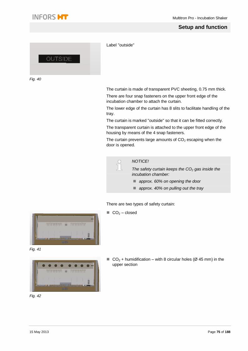
Tubes with different light spectra can be used: daylight tubes photosynthesis tubes
Fig. 45
The illumination unit is mounted on the ceiling of the incubation chamber.
The tubes have sockets at both ends (G13). The tubes can be switched on and off in pairs, as required.
Fig. 46
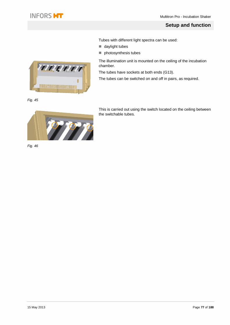
This is carried out using the switch located on the ceiling between the switchable tubes.

Multitron Pro - Incubation Shaker
Setup and function
Page 78 of 188 15 May 2013
4.14 Option “Algae” Illumination The illuminants are introduced through the side walls of the incubator shaker housing. The power supply and control elements are located on the right-hand and left-hand sides of the housing. The illumination is switched on and off using the operating panel of the incubator shaker.
Fig. 47
The walls of the incubation chamber have a white coating. The illumination is equipped with a dimmer.
Fig. 48
The inside of the door is lined with a white panel. It is used to exclude light and improve light distribution within the incubation chamber.
Fig. 49
A Plexiglas panel with a light diffuser sheet is clipped on over the illuminants.
Multitron Pro - Incubation Shaker
Setup and function
15 May 2013 Page 79 of 188
4.15 Option Pass-through
Fig. 50
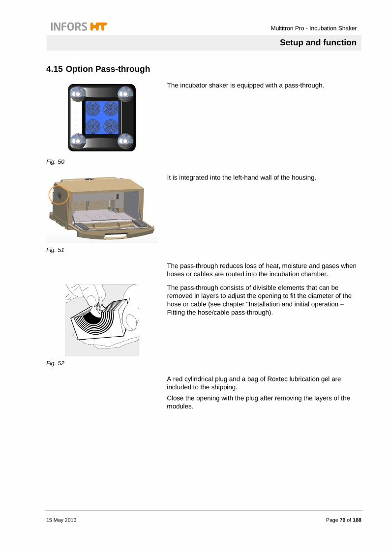
The incubator shaker is equipped with a pass-through.
Fig. 51
It is integrated into the left-hand wall of the housing.
The pass-through reduces loss of heat, moisture and gases when hoses or cables are routed into the incubation chamber.
Fig. 52
The pass-through consists of divisible elements that can be removed in layers to adjust the opening to fit the diameter of the hose or cable (see chapter "Installation and initial operation – Fitting the hose/cable pass-through).
A red cylindrical plug and a bag of Roxtec lubrication gel are included to the shipping.
Close the opening with the plug after removing the layers of the modules.
Multitron Pro - Incubation Shaker
Setup and function
Page 80 of 188 15 May 2013
4.16 Option Mobile Pt100 sensor The incubator shaker can be additionally equipped with a mobile temperature sensor that extends the functionality of the integrated temperature sensor. The mobile Pt100 sensor is integrated into the control system as a cascade, i.e. the mobile Pt100 sensor delivers additional temperature data measured in the liquid. Measurement and control are still carried out via the integrated temperature sensor.
NOTICE! The cascade control can be disabled. This involves disconnecting the mobile Pt100 sensor from the measuring unit by a qualified specialist from the equipment manufacturer.
Fig. 53
The mobile temperature sensor is inserted into a holder on the rear wall of the incubation chamber. It can be used
in a reagent flask
underneath disposable culture bags.
During operation, the mobile temperature sensor must be placed in a reference flask containing water or, if incubation is carried out in a disposal culture bag, it must be placed in its intended position underneath the bag. The temperature is controlled automatically in the cascade mode, i.e. the value measured by the mobile temperature sensor is the actual temperature of the liquid. This value is used as a reference variable for controlling the temperature inside the incubator. This has two advantages:
Control is more precise because the temperature is measured directly in the liquid. It eliminates the uncertainty associated with measuring in air due to heat transfer from the air to the liquid.
In the event of temperature jumps, e.g. for thermal induction of protein expression, the target value in the liquid can be reached much faster and more accurately.

Multitron Pro - Incubation Shaker
Setup and function
15 May 2013 Page 81 of 188
In case of a temperature jump upwards or downwards, the controller will alter the temperature of the incubator well beyond the setpoint value to speed up heat transfer from the air to the liquid and vice versa. Before the target value is reached in the liquid, the temperature in the incubation chamber is automatically adjusted to the setpoint value to avoid values beyond the setpoint.
CAUTION! Risk of damage to the sensor cable due to abrasion by moving parts. If the mobile temperature sensor is used on the moving table, the sensor cable may be abraded and damaged due to contact with moving parts. Therefore: – Ensure that the mobile temperature sensor does
not come into contact with moving parts.
Please note the following points:
If a mobile temperature sensor is installed, it must always be immersed in liquid in the reference flask
or: placed in its intended position underneath a culture bag.
When the mobile temperature sensor is inserted into its holder, it measures the air temperature. This may cause cycling of the temperature control system.
If the mobile temperature sensor is used to measure the temperature of the liquid in a reference flask, this reference flask must have the same size and must contain the same volume as the culture flasks. The use of culture flasks with different sizes is not possible because the heat transfer differs depending on the volume. If culture flasks are used whose size and volume differ significantly from those of the reference flask, this may cause the temperature to be considerably higher or lower than the setpoint value before the target temperature is eventually reached in the liquid.

Multitron Pro - Incubation Shaker
Setup and function
Page 82 of 188 15 May 2013
4.17 Option Adjustable counterweight The unit is equipped with a variable throw.
Fig. 54
The eccentric displacement of the axle allows the eccentric throw to be set to three positions:
12.5 mm 25 mm 50 mm
The counterweights are also adjustable to reduce vibrations during operation. If the tray weight is more than 12 kg (loaded, including holders) and at higher speeds, the counterweights can be set to the position HL (heavy load). The positions for mounting the two weights are marked:
Throw 12.5 / HL 25
Throw 25 / HL 50 Throw 50
Fig. 55
Underneath the table, there is a prop on the left-hand tray ejector. It is used to secure the table in the highest position while the counterweights are being fitted. The prop is hung onto the rail on the underside of the table.

Multitron Pro - Incubation Shaker
Setup and function
15 May 2013 Page 83 of 188
4.18 Option UV sterilisation of the air supply The air supply to the incubator is sterilized using two units with UV lamps that are installed between the rear wall of the housing and the lining of the incubation chamber. The UV sterilisation lamps emit high-energy UV radiation with a wavelength of 253.7 nm. The air drawn in by the cross-flow fans is fed through this light trap. The UV radiation kills any microorganisms in the air supply.
Fig. 56
The picture on the left shows the position of the UV sterilisation units behind the stainless steel lining of the incubation chamber.
The UV sterilisation units are not visible.
Fig. 57
The switch for the air sterilisation unit is located on the left-hand side wall.
The switch for units with side-mounted cooling is located on the front panel of the cooler housing.
Multitron Pro - Incubation Shaker
Transport, packaging and storage
Page 84 of 188 15 May 2013
5 Transport, packaging and storage
5.1 Safety instructions for transport
Inappropriate transportation
CAUTION! Damage due to inappropriate transportation! Inappropriate transportation may cause considerable loss of property. Therefore: – Handle packed items with care and caution
when unloading on delivery, as well as during in-house transportation.
– Remove packaging finally only when the equipment is ready to be brought into use.
5.2 Transport inspection
Immediately verify delivery on receipt for completeness and freedom from any transit damage.
Proceed as follows when transit damage is physically identifiable: Do not accept delivery or under reserve only.
Note extent of loss on transport documentation or delivery note. Initiate complaint.
NOTICE! Complain regarding a defect as soon as it is identified. Claims for damages can only be made within the effective terms for presenting complaints according to the manufacturer’s general conditions of contract

Multitron Pro - Incubation Shaker
Transport, packaging and storage
15 May 2013 Page 85 of 188
5.3 Packaging
CAUTION! Risk of material damage – particularly the window – due to scratches caused by using sharp-edged or pointed tools when opening the packaging. Therefore: – Do not use pointed tools to open the packaging.
Packaging Only environmental friendly packaging materials are used. The unit and its accessories are packed in a crate (wood and/or corrugated cardboard) on a EURO pallet. The packaging is intended to protect the individual components against damage during transport, etc. Therefore, do not destroy the packaging and do not remove it just before starting initial operation.
5.4 Transport
CAUTION! Risk of damage due to extreme localised loads. An extreme localised load may cause the feet to shear off or leave dents in the base plate. Therefore: – Never push the unit.
Owing to its weight, the incubator shaker must never be transported or moved by one person alone.
If the unit has to be relocated over a long distance within the building, it is essential to use a stacker truck or a trolley. When transporting with a stacker truck, the unit must be set down very carefully in a vertical position on the floor. Transport on a trolley must be carried out with extreme care. Never transport the unit without fitting the transport lock first; see "Installation and commissioning – Fitting the transport lock".
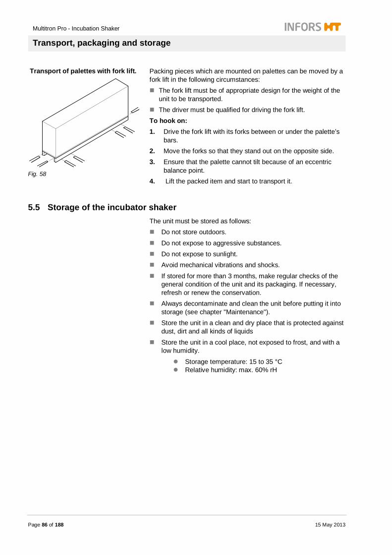
Multitron Pro - Incubation Shaker
Transport, packaging and storage
Page 86 of 188 15 May 2013
Transport of palettes with fork lift.
Fig. 58
Packing pieces which are mounted on palettes can be moved by a fork lift in the following circumstances:
The fork lift must be of appropriate design for the weight of the unit to be transported.
The driver must be qualified for driving the fork lift. To hook on: 1. Drive the fork lift with its forks between or under the palette’s
bars. 2. Move the forks so that they stand out on the opposite side. 3. Ensure that the palette cannot tilt because of an eccentric
balance point. 4. Lift the packed item and start to transport it.
5.5 Storage of the incubator shaker The unit must be stored as follows:
Do not store outdoors.
Do not expose to aggressive substances. Do not expose to sunlight. Avoid mechanical vibrations and shocks.
If stored for more than 3 months, make regular checks of the general condition of the unit and its packaging. If necessary, refresh or renew the conservation.
Always decontaminate and clean the unit before putting it into storage (see chapter "Maintenance").
Store the unit in a clean and dry place that is protected against dust, dirt and all kinds of liquids
Store the unit in a cool place, not exposed to frost, and with a low humidity.
Storage temperature: 15 to 35 °C Relative humidity: max. 60% rH

Multitron Pro - Incubation Shaker
Installation and initial operation
15 May 2013 Page 87 of 188
6 Installation and initial operation
Faulty installation or incorrect initial operation
WARNING! Danger due to faulty installation or incorrect initial operation! Installation and initial operation requires qualified and experienced personnel. Faulty installation may lead to perilous situations or severe loss of property. Therefore: – Installation and initial operation are to be carried
out by the manufacturer’s associates only. – Call the manufacturer when any subsequent
translocation is foreseen. – Prevent arbitrary installation and translocation
6.1 Safety Personnel Installation and initial operation may only be carried out by
qualified personnel.
Electrical system
DANGER! Danger of fatal electric shock! Contact with electrically powered components is perilous. Energised electrical components may perform uncontrolled movements which can lead to severe injuries. Therefore: – Turn off the electrical supply and check whether
it is electrically isolated before starting any work.
Multitron Pro - Incubation Shaker
Installation and initial operation
Page 88 of 188 15 May 2013
Inappropriate installation and initial operation
WARNING! Risk of injury due to inappropriate installation and initial operation! Inappropriate installation and initial operation may lead to severe damage to persons or loss of property. Therefore: – Make sure that enough space is provided for
the installation before starting. – Take care regarding sharp-edged components – Keep the installation site tidy and clean!
Discarded components and tools may be a source of accidents.
– Component parts must be installed professionally.
– Secure component parts so that they cannot fall off or tumble.
6.2 Location requirements for installation
6.2.1 Place of installation The following requirements must be met for the installation of the unit:
The equipment must be installed and operated inside a building.
The unit must not be exposed to direct sunlight.
NOTICE! The incubator shaker must be protected against hot exhaust air of other equipment with cooling systems.
Ambient temperature must lie within the following range:
Minimum: 1 °C Maximum: 30 °C Without cooling: not more than 5 °C below the minimum
incubation temperature With cooling: not more than 20 °C above the minimum
incubation temperature
Protect the unit against mechanical damage (trolleys, being kicked, etc.).
The installation site must be level, sufficiently stable and able to bear loads.
Multitron Pro - Incubation Shaker
Installation and initial operation
15 May 2013 Page 89 of 188
There must not be any sources of electrical interference near the unit.
All interfaces and switches on the unit must be readily accessible.
NOTICE! The main switch of the incubator shaker must be completely unobstructed and readily accessible.
Ensure that the workplace is sufficiently illuminated. Protect the operating panel against splashed water.
Protect the outside of the unit against extreme levels of dust and dirt.
NOTICE! Any other type of installation must first be checked with the manufacturer and requires the written permission of the manufacturer
6.2.2 Minimum distances The incubator shaker must be set up as follows for operation, handling and repair work:
NOTICE! Main switch and cable for power supply must be easily and freely accessible.
To provide a good circulation of air following distances are necessary:
Right side: Minimum 8 cm Backside: Minimum 8 cm
Top: Minimum 10 cm The dimensions of the different models are given in the chapter "Technical Data".

Multitron Pro - Incubation Shaker
Installation and initial operation
Page 90 of 188 15 May 2013
6.3 Removing the transport lock Before the unit can be put into operation, the transport lock must be released and removed:
Procedure
Fig. 59
1. Release and remove the star knob screw.
2. Store the screw and the supplied tools together for future transports.

Multitron Pro - Incubation Shaker
Installation and initial operation
15 May 2013 Page 91 of 188
6.4 Mounting the drain nozzle Before commissioning, the supplied hose nozzle must be screwed into the drain hole:
Procedure
Fig. 60
1. Unscrew the blanking plug from the drain hole.
Fig. 61
2. Screw in the hose nozzle.
NOTICE! To drain condensate or rinsing fluids, mount one end of a hose onto the nozzle and place the other end in a suitable container.
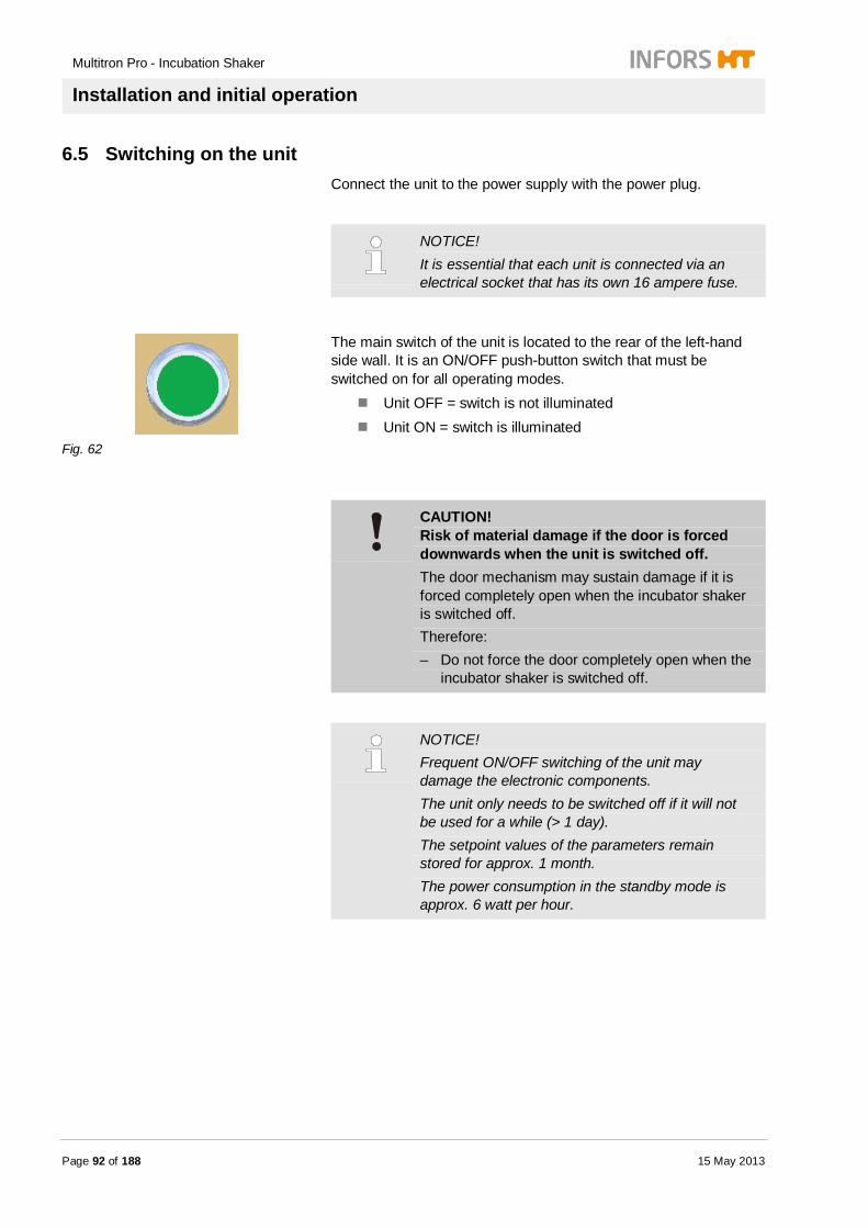
Multitron Pro - Incubation Shaker
Installation and initial operation
Page 92 of 188 15 May 2013
6.5 Switching on the unit Connect the unit to the power supply with the power plug.
NOTICE! It is essential that each unit is connected via an electrical socket that has its own 16 ampere fuse.
Fig. 62
The main switch of the unit is located to the rear of the left-hand side wall. It is an ON/OFF push-button switch that must be switched on for all operating modes.
Unit OFF = switch is not illuminated Unit ON = switch is illuminated
CAUTION! Risk of material damage if the door is forced downwards when the unit is switched off. The door mechanism may sustain damage if it is forced completely open when the incubator shaker is switched off. Therefore: – Do not force the door completely open when the
incubator shaker is switched off.
NOTICE! Frequent ON/OFF switching of the unit may damage the electronic components. The unit only needs to be switched off if it will not be used for a while (> 1 day). The setpoint values of the parameters remain stored for approx. 1 month. The power consumption in the standby mode is approx. 6 watt per hour.

Multitron Pro - Incubation Shaker
Installation and initial operation
15 May 2013 Page 93 of 188
6.6 Installing the incubator shaker
CAUTION! Risk of material damage due to uncontrolled movement of the unit. The unit may start moving around uncontrollably if it is placed on a slippery surface. Therefore: – Place a non-slip mat under each foot.
CAUTION! Risk of material damage due to uncontrolled movement If the unit has not been leveled properly it may move around uncontrollably if it starts to vibrate. Therefore: – If the unit shows any signs of vibration or
unusual movements, level it again.
Rubber feet The bench model cannot be leveled out. It must stand on a firm, flat surface.
Trolley
NOTICE! The trolley cannot be leveled out. Remove both front castors out of the frame before starting initial operation.
Procedure 1. Lift the incubator shaker with a stacker truck.
Fig. 63
2. Pull the front castors out of the frame.
3. Set the unit down again carefully.
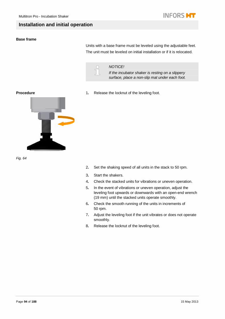
Multitron Pro - Incubation Shaker
Installation and initial operation
Page 94 of 188 15 May 2013
Base frame Units with a base frame must be leveled using the adjustable feet. The unit must be leveled on initial installation or if it is relocated.
NOTICE! If the incubator shaker is resting on a slippery surface, place a non-slip mat under each foot.
Procedure
Fig. 64
1. Release the locknut of the leveling foot.
2. Set the shaking speed of all units in the stack to 50 rpm.
3. Start the shakers. 4. Check the stacked units for vibrations or uneven operation. 5. In the event of vibrations or uneven operation, adjust the
leveling foot upwards or downwards with an open-end wrench (19 mm) until the stacked units operate smoothly.
6. Check the smooth running of the units in increments of 50 rpm.
7. Adjust the leveling foot if the unit vibrates or does not operate smoothly.
8. Release the locknut of the leveling foot.

Multitron Pro - Incubation Shaker
Installation and initial operation
15 May 2013 Page 95 of 188
6.7 Setting the capillary thermostat The capillary thermostat oft he incubation chamber has a default setting of 70 °C. This is 5 °C above the maximum operating temperature oft he unit, e.g. 65 °C. The absolute tolerance oft he thermostat is 2.5 °C.
Procedure
1. Set the thermostat to 70 °C.
2. Shut the door of the unit. 3. Switch on the unit.
4. Press option key to select the temperature parameter.
The temperature parameter lights up.
5. Press Set key.
Setpoint lights up.
6. Press the PLUS key until the maximum operating temperatur (e.g. 50 °C) is set.
7. Press the ON/OFF key to switch on the temperature control system.
8. Wait until the upper desplay has reached the setpoint value (e.g. 50 °C).

Multitron Pro - Incubation Shaker
Installation and initial operation
Page 96 of 188 15 May 2013
9. Open the door.
10. Turn the thermostat down slowly until there is an audible click at the actuation point of the thermostat.
11. Set the thermostat 5 °C higher.
NOTICE! The thermostat must be set a few °C higher than the maximum operation temperature to allow a continuous control.
The thermostat is now set. The maximum operating temperature now corresponds to the specified setpoint shown in the display.
6.8 Setting the adjustable counterweight The counterweight with a variable throw is equipped with two detachable weights that can be flexibly mounted. These weights are positioned according to the throw and the load. The throw can be altered with an adjustable axle.
CAUTION! Risk of material damage due to use of too high shaking speed! The incubation shaker may move due to vibrations caused by too high shaking speeds and may cause damage at the site. Therefore: – Never set speed value over given values of the
specifications in chapter „Technical Data“. – Place equipment on an anti-slip matting – Inform operator about throw settings

Multitron Pro - Incubation Shaker
Installation and initial operation
15 May 2013 Page 97 of 188
6.8.1 Changing the throw Change the throw as follows:
Procedure
Fig. 65
1. Remove the 4 Allen screws from the table.
Fig. 66
2. Lift the table.
Fig. 67
3. Support the table with the prop.

Multitron Pro - Incubation Shaker
Installation and initial operation
Page 98 of 188 15 May 2013
Fig. 68
4. Remove the bearing sleeve and self-aligning ball bearing (highlighted in yellow) from the adjustable axle.
Fig. 69
5. Remove the 4 Allen screws from the adjustable throw axle.
Fig. 70
6. Insert the throw axle into the desired throw position.
12.5 mm 25 mm 50 mm
The marking on the edge of the throw axle must line up with the marking on the counterweight. The different throws are engraved on the counterweight.
7. Attach the adjustable throw axle to the counterweight using the 4 Allen screws.

Multitron Pro - Incubation Shaker
Installation and initial operation
15 May 2013 Page 99 of 188
NOTICE! Tighten the 4 Allen screws crosswise and uniformly,
8. Fit the self-aligning ball bearing and bearing sleeve on the
axle.
6.8.2 Adjusting the detachable counterweights
Procedure
Fig. 71
1. Remove the Allen screws securing the detachable counterweights.
2. Remove the detachable weights from the counterweight. 3. Insert the cylindrical pins in the desired counterweight
positions. 4. Place the detachable counterweights in their desired positions
on the counterweight. 5. Screw in the Allen screws to secure the detachable
counterweights.
Fig. 72
6. Hold the table with one hand and press the prop into its holder.

Multitron Pro - Incubation Shaker
Installation and initial operation
Page 100 of 188 15 May 2013
Fig. 73
7. Fit the table onto the drive axle.
Fig. 74
8. Insert the 4 Allen screws of the table and tighten cross-wise.
6.9 Switching on the cooling system
NOTICE! The nominal cooling capacity can only be reached if the ambient temperature at the cooling aggregate is below 30 °C. Ensure sufficient air circulation. See chapter "Installation".
Side-mounted cooling system
The side-mounted cooling system can be put into operation without any previous preparatory work.
External cooling system The cooling register must be connected to the external cooling system via a feed hose and a return hose.
Top-mounted cooling system The top-mounted cooling system must be filled with cooling liquid before it is put into service.

Multitron Pro - Incubation Shaker
Installation and initial operation
15 May 2013 Page 101 of 188
The supplied cooling liquid is diluted. The mixture has a mixing ratio of 9:2 (distilled water : coolant).
CAUTION! Risk of material damage due to the use of an unsuitable cooling liquid. The copper piping of the cooling system can be damaged by corrosion if an unsuitable cooling liquid is used. Therefore: – Use only copper-compatible cooling liquids
suitable for use in the food and pharmaceutical sectors
– Pay attention to the level of cooling liquid in the tank
6.10 Filling with cooling liquid
CAUTION! Risk of material damage due to dry-running of the pump and insufficient cooling. If cooling systems with a coolant circuit (top-mounted or base cooling systems) are not filled with the supplied coolant before initial operation, this will have a negative effect on the cooling efficiency and will damage the pump if it runs dry. Therefore: – Before initial operation, fill the coolant system
with the separately supplied coolant (Antifrogen L, copper-compatible and approved for use in the food and pharmaceutical industries; based on propylene glycol / 1,2-propandiol) (See also the warning sticker on the unit)
NOTICE! The cooling liquid is not physiologically harmful. Nevertheless, avoid contact with skin and eyes. If swallowed, drink plenty of fresh water and seek medical advice, if necessary.
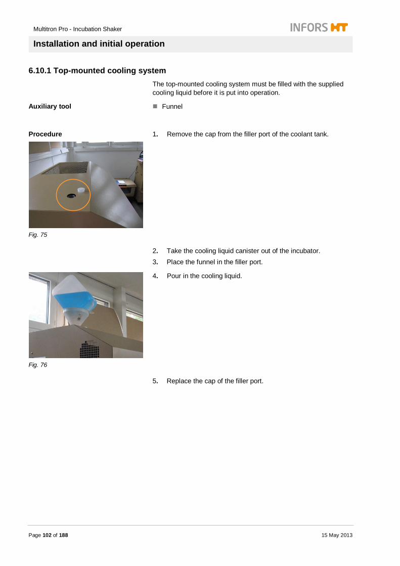
Multitron Pro - Incubation Shaker
Installation and initial operation
Page 102 of 188 15 May 2013
6.10.1 Top-mounted cooling system The top-mounted cooling system must be filled with the supplied cooling liquid before it is put into operation.
Auxiliary tool Funnel
Procedure
Fig. 75
1. Remove the cap from the filler port of the coolant tank.
2. Take the cooling liquid canister out of the incubator. 3. Place the funnel in the filler port.
Fig. 76
4. Pour in the cooling liquid.
5. Replace the cap of the filler port.
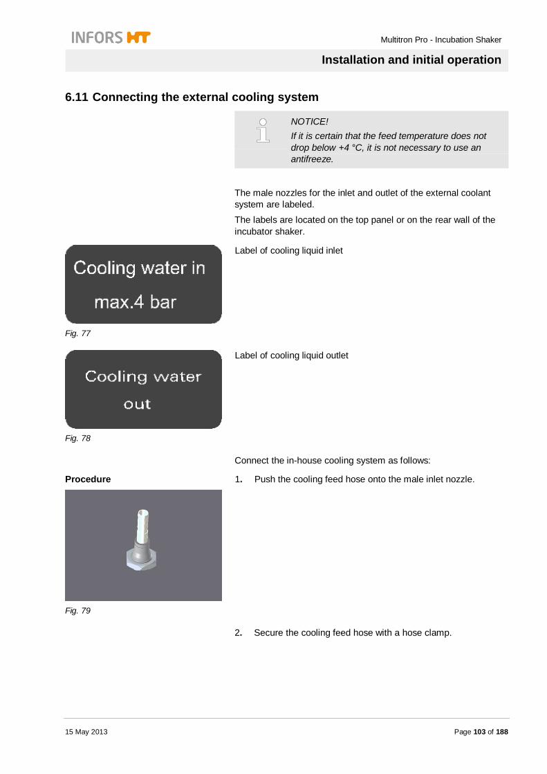
Multitron Pro - Incubation Shaker
Installation and initial operation
15 May 2013 Page 103 of 188
6.11 Connecting the external cooling system
NOTICE! If it is certain that the feed temperature does not drop below +4 °C, it is not necessary to use an antifreeze.
The male nozzles for the inlet and outlet of the external coolant system are labeled.
The labels are located on the top panel or on the rear wall of the incubator shaker.
Fig. 77
Label of cooling liquid inlet
Fig. 78
Label of cooling liquid outlet
Connect the in-house cooling system as follows:
Procedure
Fig. 79
1. Push the cooling feed hose onto the male inlet nozzle.
2. Secure the cooling feed hose with a hose clamp.
Multitron Pro - Incubation Shaker
Installation and initial operation
Page 104 of 188 15 May 2013
Fig. 80
3. Push the cooling return hose onto the male outlet nozzle.
4. Secure the cooling return hose with a hose clamp.
6.12 Connecting the Direct Steam Humidification
CAUTION! Risk of material damage due to build up of lime scale through use of tap water. Lime scale may build up in the evaporator and the incubation chamber through the use of tap water. Therefore: – Use only the recommended types of water for
humidification.
Before starting initial operation the Direct Steam Humidification, it must be connected to an unpressurised water tank or to a pressurized water supply. The inlet pressure must not exceed 0.3 bars.
NOTICE! Place the water tank on the floor to avoid damaging the equipment and the electronics. The water tank must fulfill the following conditions:
closed capable of being sterilized equipped with a filter for pressure compensation
sufficient filling for one cycle located <2 m away from the incubator shaker Altitude <1.60 m above floor, if not placeable on
the floor.
Multitron Pro - Incubation Shaker
Installation and initial operation
15 May 2013 Page 105 of 188
Approved types of water (see Appendix): Distilled water Deionized water
Demineralized water Reverse osmosis water
The Direct Steam Humidification is equipped with a Schott quickfit connector.
The feed hoses must be mounted on the Schott connectors as follows:
Direct mounting of hoses
Procedure 1. Cut the end of the hose cleanly.
Fig. 81
2. Insert the hose as far as it will go into the quickfit connector.
Mounting the hose nozzle plus hose Instead of mounting the hose, a hose plus a male nozzle can be inserted into the Schott quickfit connector.
Procedure 1. Insert the male hose nozzle into the Schott quickfit connector.
2. Push the hose onto the hose nozzle. 3. Secure the hose with a hose clamp.

Multitron Pro - Incubation Shaker
Installation and initial operation
Page 106 of 188 15 May 2013
6.13 Connecting the CO2 gas supply
Fig. 82
The inlet hose nozzle for the CO2 supply is located on the right-hand wall of the housing.
The gassing unit is equipped with a control valve and a CO2 sensor.
The CO2 sensor is located on the left-hand side of the rear wall of the incubation chamber.
The gassing unit is operated via the operating panel.
The in-house supply of air or gas to the unit must meet the following requirements:
Requirements for air/gas supply Constancy of the air/gas supply The air/gas must be clean, dry, oil- and dust-free.
Requirements for the hose Only pressure-resistant and intact hoses may be used The hose must have an appropriate diameter; an adapter may
be used, if necessary.
Secure hoses with hose clamps
6.14 Connecting the gassing pipe The in-house supply of air or gas to the unit must meet the following requirements:
Requirements for air/gas supply Constancy of the air/gas supply The air/gas must be clean, dry, oil- and dust-free.
Requirements for the hose Only pressure-resistant and intact hoses may be used The hose must have an appropriate diameter; an adapter may
be used, if necessary.
Secure hoses with hose clamps
Multitron Pro - Incubation Shaker
Operation
15 May 2013 Page 107 of 188
7 Operation
7.1 Safety
Personnel The incubator shaker may only be operated by qualified chemistry, biology or bio-technology technicians or by personnel who have been appropriately instructed by qualified chemistry, biology or bio-technology technicians.
All work associated with preparations for cultivation and the cultivation process must be carried out by qualified chemistry, biology or bio-technology technicians or by personnel who have been appropriately instructed by qualified chemistry, biology or bio-technology technicians.
Inappropriate operation
WARNING! Risk of injury due to inappropriate operation! Inappropriate operation may lead to severe physical injury or loss of property. Therefore: – Strictly follow the instructions stated in this
operating manual.
CAUTION! Risk of burns on touching hot surfaces. There is a risk of burns from hot surfaces if the table and/or cultivation flasks are touched when the unit is operating at temperatures above 50 °C. Therefore: – Always wear safety gloves.
CAUTION! Risk of injury due to broken glass or shards from glass cultivation flasks. Broken or splintered cultivation flasks can injure hands and eyes. Therefore: – Always wear safety glasses. – Always wear suitable safety gloves. – Always use undamaged cultivation flasks.
Multitron Pro - Incubation Shaker
Operation
Page 108 of 188 15 May 2013
7.2 Switching on the unit
The unit is switched on with the green button located on the side of the housing.
ON = button is illuminated. OFF = button is not illuminated.
The initialization phase of the unit is shown on both displays. The unit is not ready for operation until this phase is complete. The initialization information disappears automatically when the initialization is complete.
Both displays show the version of the control type, e.g. Std for standard.
Following the version of firmware is displayed, e.g. Firmware 3.02.
Finally the access mode for the service mode is active for a few seconds (for authorized personnel only).
Displays change to operating mode subsequently. Parameters temperature and RPM are shown in the displays.
The operation mode of the parameters are shown (OFF or the current value).

Multitron Pro - Incubation Shaker
Operation
15 May 2013 Page 109 of 188
7.3 General operation The unit is operated either directly using the operating panel oft he unit or externally.
The warning sign lights up when the unit is operated.
If the unit is operated externally, the EXTERN sign lights up.
The unit can be operated externally using any of the operating panels on the stack of units.
Fig. 83
Display area
In the display area there are two alpha-numeric displays with 4 characters, parameter signs, function signs and unit symbols.
Alpha-numeric display with 4 characters:
This displays show parameter values, alarm messages, error messages and unit modes.
Function area
Display area
Messages
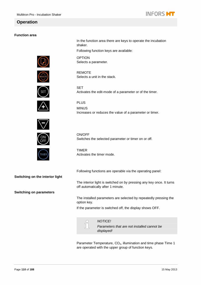
Multitron Pro - Incubation Shaker
Operation
Page 110 of 188 15 May 2013
Function area In the function area there are keys to operate the incubation shaker. Following function keys are available:
OPTION Selects a parameter.
REMOTE Selects a unit in the stack.
SET Activates the edit-mode of a parameter or of the timer.
PLUS MINUS Increases or reduces the value of a parameter or timer.
ON/OFF Switches the selected parameter or timer on or off.
TIMER Activates the timer mode.
Following functions are operable via the operating panel:
Switching on the interior light The interior light is switched on by pressing any key once. It turns off automatically after 1 minute.
Switching on parameters The installed parameters are selected by repeatedly pressing the option key.
If the parameter is switched off, the display shows OFF.
NOTICE! Parameters that are not installed cannot be displayed!
Parameter Temperature, CO2, illumination and time phase Time 1 are operated with the upper group of function keys.

Multitron Pro - Incubation Shaker
Operation
15 May 2013 Page 111 of 188
Parameter RPM, Humidity, O2 and time phase Time 2 are operated with the lower group of function keys.
The SET key activates the edit mode of a parameter or timer. The ON/OFF key switches a selected parameter or timer on or off. The parameter sign lights up, when parameter is switched on. The display shows the current value of the parameter when the parameter is switched on.
Setting parameter values Pressing the SET key the parameter value can be edited. If parameter is in edit mode, SETPOINT lights up.
Holding the PLUS or MINUS key initially increases or respectively decreases the parameter value in small increments and subsequently with the next biggest increment.
Increments:
RPM: 1 RPM – 10 RPM Temperature: 0.1 °C – 1 °C Humidity: 0.1 %rH – 1 %rH CO2: 0.1 % - 1 % Timer: 1 min – 10 min – 30 min - 1 h– 12 h
NOTICE! The setpoint values of the parameters do not have to be confirmed. They are accepted after entry without confirmation.
The parameter can be switched on with the ON/OFF key. The control system returns to the operation mode when no key is pressed for a longer time (approx. 5 sec.).
Message SETPOINT is off. Setting the timer
Pressing the TIMER key activates the set-up mode of the timer function.
With the upper group of the function key, Phase 1 can be operated. Pressing the SET key, activates the set-up mode of the timer.
Pressing the option key repeatedly, selects phase 1 or phase 2 of the timer. Finally set all required parameters and switch them on.
NOTICE! All set parameters in Phase 2 only will be activated, if Phase 1 in the timer is switched on.

Multitron Pro - Incubation Shaker
Operation
Page 112 of 188 15 May 2013
Finally the setting mode of the time is closed, when the option key is pressed. All settings will be saved without an additional confirmation.
Setting timer for a multiple-changeover (cycling) If Phase 1 and Phase 2 of the timer are switched on, the incubation shaker alters between operating mode of Phase 1 and Phase 2 with the set time interval.
If Time 1 and Time 2 are switched on, the cycle symbol lights blue.
7.4 Operating the timer 7.4.1 Displaying the time
In the upper display the time of Phase 1 (Time 1) is shown.
In the lower display the time of Phase 2 (Time 2) is shown.
The duration will be displayed as follows:
Display time
From 1 up to 59 minutes
From 1 hours 00 minutes up to 23 hours 59 minutes

Multitron Pro - Incubation Shaker
Operation
15 May 2013 Page 113 of 188
From 1 day 0 hours up to 9 days 23 hours
7.4.2 Continuous operation without timer
The timer is switched off. The timer function symbol does not light up. The shaker operates continuously with the preset parameters.
7.4.3 Setting the timer
The timer can be used to change over between two operating modes. This can be a single changeover to continuous changeover. Time 1 and Time 2 can be set with the TIMER key.
In operating mode Time 1 all parameters are set, that are active in Phase 1. In operating mode Time 2 all parameters are set, that are active in Phase 2.
NOTICE! Do not activate the timer in Time 2. This starts the programmed cycle.
CAUTION! Using the «Sticky Stuff» adhesive matting, there is a risk of loss of property due to condensation caused by sudden drops in temperature! Do not program jumps in temperature with the timer, while using «Sticky Stuff» adhesive matting. This may lead to condensation and thus cause the cultivation flasks to detach from the adhesive matting! Therefore: – Never program temperature jumps with the
timer.

Multitron Pro - Incubation Shaker
Operation
Page 114 of 188 15 May 2013
7.4.4 Setting the timer for a single changeover The timer can be used for a single changeover of the cultivation parameters after a specific time. For setting the timer for a single change proceed as follows:
Procedure
1. Press TIMER key.
Time 1 and Time 2 light up blue. To operate Time 1 use the upper function keys. To operate Time 2 use the lower function keys.
2. Press option key to select Time 1.
3. Press SET key.
4. Press PLUS key to set time for Phase 1.
5. Press ON/OFF key to switch on Time 1.
Timer 2 is switched off.
6. Press option key to select parameter.
7. Press SET key.
8. Press PLUS or MINUS key to set setpoint.
9. Press ON/OFF key to switch parameter on.
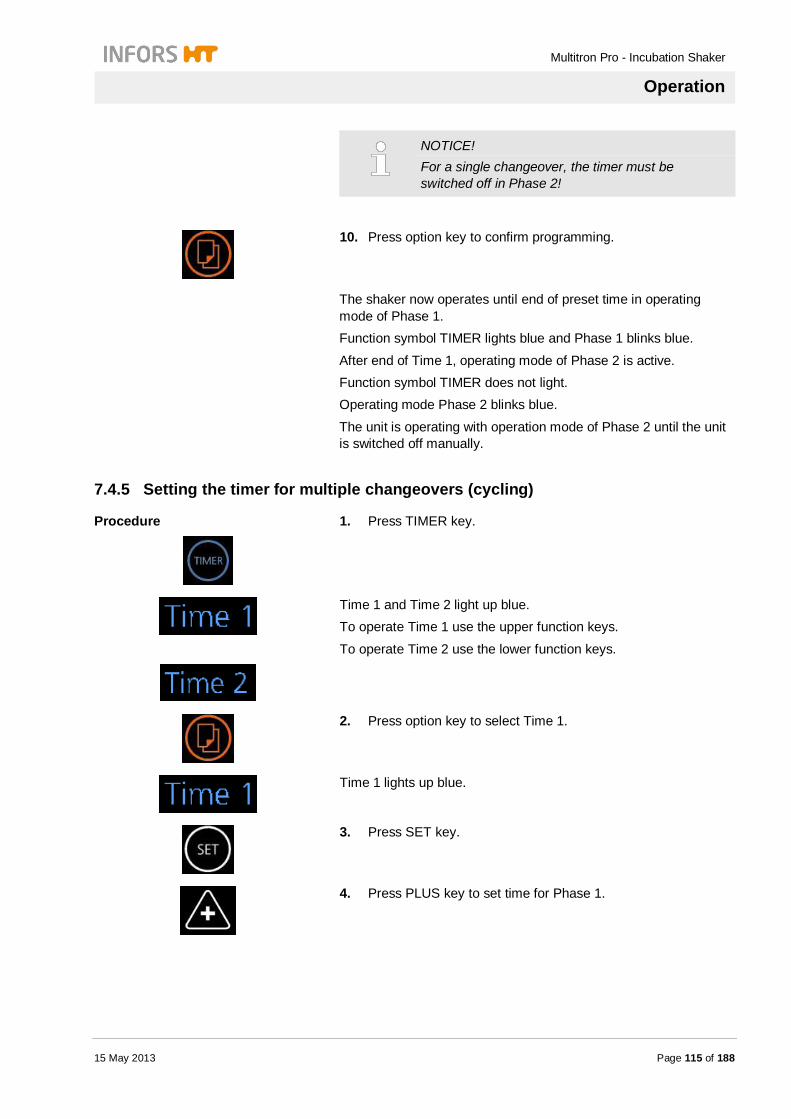
Multitron Pro - Incubation Shaker
Operation
15 May 2013 Page 115 of 188
NOTICE! For a single changeover, the timer must be switched off in Phase 2!
10. Press option key to confirm programming.
The shaker now operates until end of preset time in operating mode of Phase 1. Function symbol TIMER lights blue and Phase 1 blinks blue.
After end of Time 1, operating mode of Phase 2 is active. Function symbol TIMER does not light. Operating mode Phase 2 blinks blue.
The unit is operating with operation mode of Phase 2 until the unit is switched off manually.
7.4.5 Setting the timer for multiple changeovers (cycling)
Procedure
1. Press TIMER key.
Time 1 and Time 2 light up blue. To operate Time 1 use the upper function keys.
To operate Time 2 use the lower function keys.
2. Press option key to select Time 1.
Time 1 lights up blue.
3. Press SET key.
4. Press PLUS key to set time for Phase 1.

Multitron Pro - Incubation Shaker
Operation
Page 116 of 188 15 May 2013
5. Press ON/OFF to switch Time 1 on.
6. Set setpoint of parameters for Time 1 as described in chapter „Starting a work cycle“
7. Press option key to select Time 2.
Time 2 lights up blue.
8. Press SET key.
9. Press PLUS key to set time for Phase 2.
10. Press ON/OFF to switch Time 2 on.
11. Press option key to select parameter.
12. Set setpoint of parameters for Time 1 as described in chapter „Starting a work cycle“
13. Press option key to finish programming of the timer.
When both time phases are active, the cycle symbol lights up.
Settings are saved now. Operation mode of Phase 1 and Phase 2 are blinking when they are active.
7.4.6 Display the remaining runtime of the timer The following timer modes can be displayed during the first timer interval (Phase 1) of the incubation process:
Remaining runtime by pressing the TIMER key.
Remaining runtime by pressing the TIMER key and then pressing the SET key.

Multitron Pro - Incubation Shaker
Operation
15 May 2013 Page 117 of 188
7.5 Selecting a unit in a stack In the standard operating mode, the currently selected unit ist hat to which the operating panel belongs. For example, the lowest unit in a stack of 3 is always the „bottom unit“. For stacked units, any of the operating panels in the stack can be used to control each unit individually or all units.
NOTICE! The units in a stack are assigned from the bottom to top.
Symbol for selection a unit
The symbol on the operating panel for selecting units shows that all 3 units are selected for remote access.
External operation of a unit
NOTICE! The timer function cannot be operated from remote! Units that are under operation of the timer cannot be accessed by remote!
All units must be switched on using the main switch so that they can be selected via the control system.
Procedure
1. Press REMOTE key to select a unit.
Bottom unit is selected.
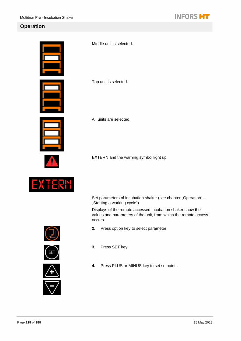
Multitron Pro - Incubation Shaker
Operation
Page 118 of 188 15 May 2013
Middle unit is selected.
Top unit is selected.
All units are selected.
EXTERN and the warning symbol light up.
Set parameters of incubation shaker (see chapter „Operation“ – „Starting a working cycle“)
Displays of the remote accessed incubation shaker show the values and parameters of the unit, from which the remote access occurs.
2. Press option key to select parameter.
3. Press SET key.
4. Press PLUS or MINUS key to set setpoint.
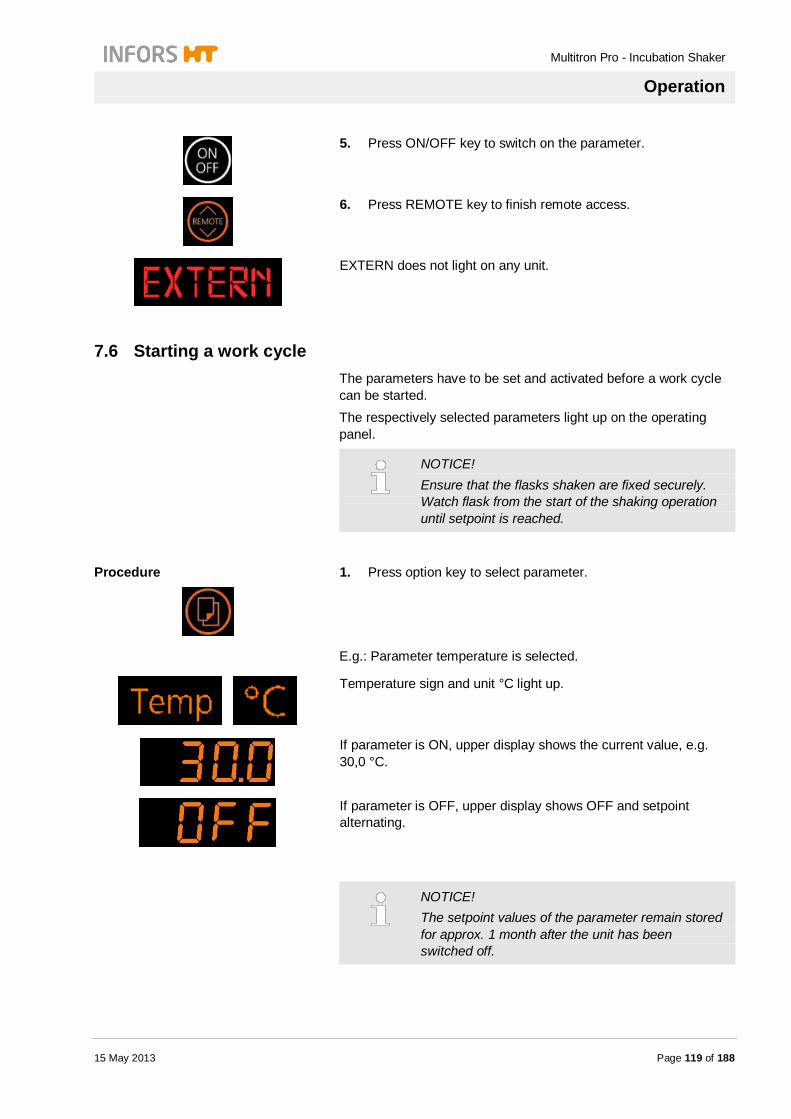
Multitron Pro - Incubation Shaker
Operation
15 May 2013 Page 119 of 188
5. Press ON/OFF key to switch on the parameter.
6. Press REMOTE key to finish remote access.
EXTERN does not light on any unit.
7.6 Starting a work cycle The parameters have to be set and activated before a work cycle can be started. The respectively selected parameters light up on the operating panel.
NOTICE! Ensure that the flasks shaken are fixed securely. Watch flask from the start of the shaking operation until setpoint is reached.
Procedure
1. Press option key to select parameter.
E.g.: Parameter temperature is selected.
Temperature sign and unit °C light up.
If parameter is ON, upper display shows the current value, e.g. 30,0 °C.
If parameter is OFF, upper display shows OFF and setpoint alternating.
NOTICE! The setpoint values of the parameter remain stored for approx. 1 month after the unit has been switched off.
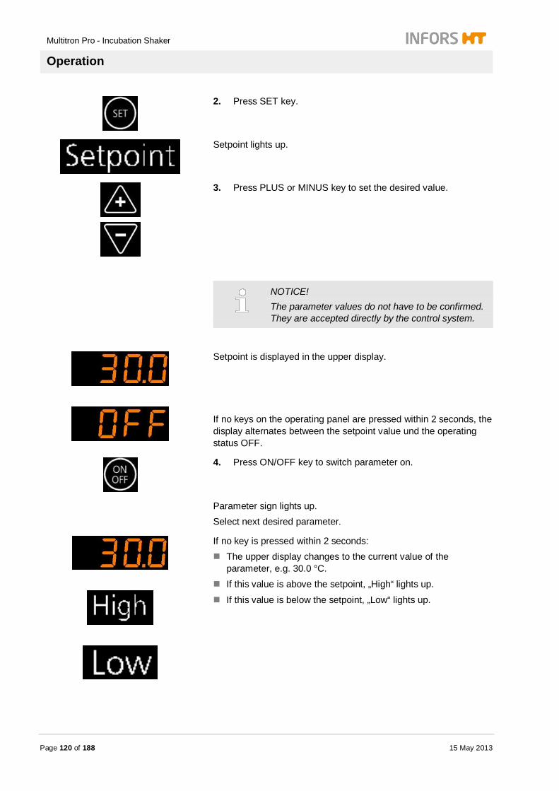
Multitron Pro - Incubation Shaker
Operation
Page 120 of 188 15 May 2013
2. Press SET key.
Setpoint lights up.
3. Press PLUS or MINUS key to set the desired value.
NOTICE! The parameter values do not have to be confirmed. They are accepted directly by the control system.
Setpoint is displayed in the upper display.
If no keys on the operating panel are pressed within 2 seconds, the display alternates between the setpoint value und the operating status OFF.
4. Press ON/OFF key to switch parameter on.
Parameter sign lights up. Select next desired parameter.
If no key is pressed within 2 seconds: The upper display changes to the current value of the
parameter, e.g. 30.0 °C. If this value is above the setpoint, „High“ lights up.
If this value is below the setpoint, „Low“ lights up.

Multitron Pro - Incubation Shaker
Operation
15 May 2013 Page 121 of 188
Switch on illumination parameter Parameter illumination can only change its mode.
Procedure 1. Switch on illumination „Algae“ on the switch at the housing.
2. Press option to select illumination.
Parameter Light lights up.
3. Press SET key.
4. Press ON/OFF key to switch on parameter illumination.
Alternating display
All parameters will be shown in the displays alternatingly. The display shows current value, if parameter is switched on. The display shows OFF, if parameter is switched off.
Static: Temperature sign lights.
Upper display shows current value, if switched on. If parameter is switched off, display shows OFF.
Sy

Multitron Pro - Incubation Shaker
Operation
Page 122 of 188 15 May 2013
7.7 Ending a work cycle To complete or terminate a work cycle, the corresponding parameter have to be deactivated.
Procedure
1. Press option key to select the parameter.
2. Press SET key.
3. Press ON/OFF key to switch off the parameter.
The display shows OFF.
CAUTION! Risk of material damage due to automatic start-up of the incubator shaker. If a work cycle is incorrectly terminated by switching off the unit with the main switch, the unit can restart automatically when it is switched on again. This may damage the incubator shaker and the cultures. Therefore: – Never terminate a work cycle using the main
switch of the unit – Do not leave any objects in the incubation
chamber when the unit is switched off. – Always make sure that the tray is inserted
correctly.
NOTICE! Disconnect incubation shaker from power supply when not using the unit for a longer period of time.
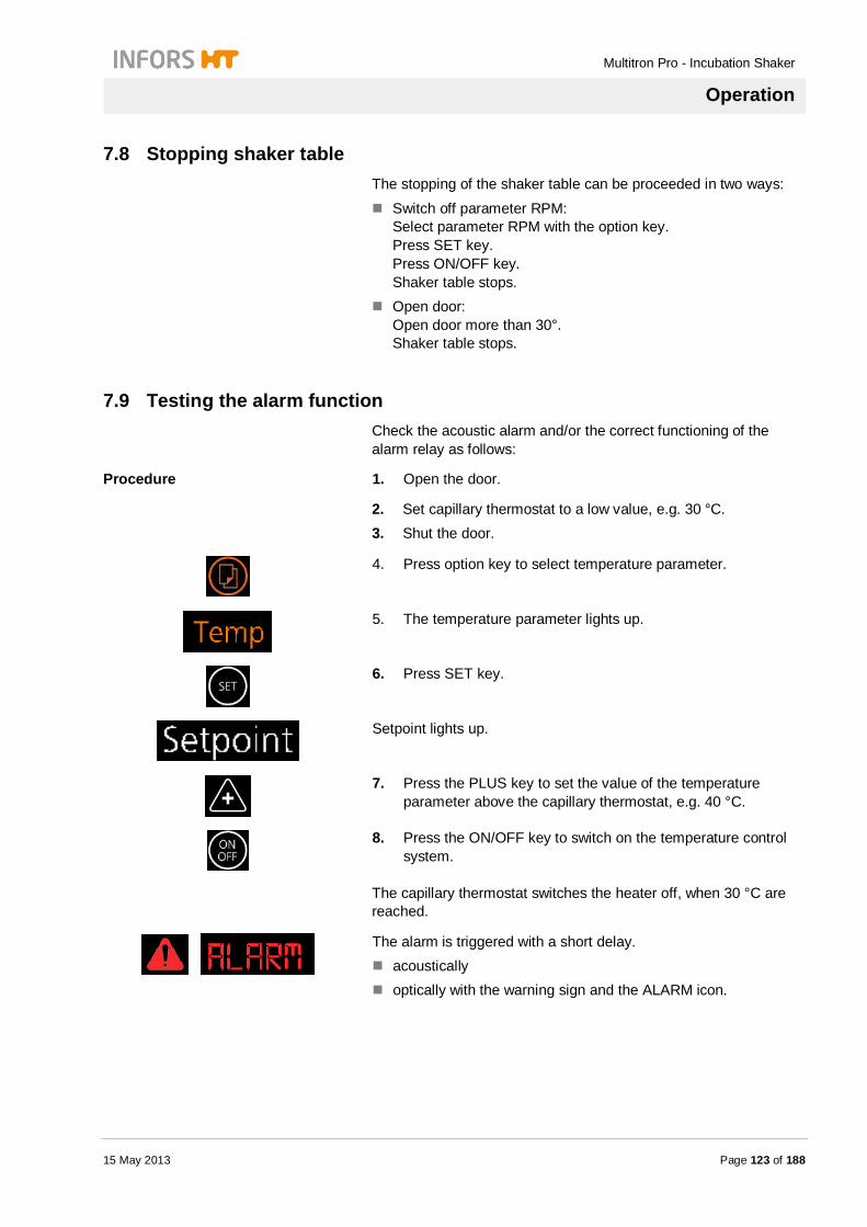
Multitron Pro - Incubation Shaker
Operation
15 May 2013 Page 123 of 188
7.8 Stopping shaker table The stopping of the shaker table can be proceeded in two ways:
Switch off parameter RPM: Select parameter RPM with the option key. Press SET key. Press ON/OFF key. Shaker table stops.
Open door: Open door more than 30°. Shaker table stops.
7.9 Testing the alarm function Check the acoustic alarm and/or the correct functioning of the alarm relay as follows:
Procedure 1. Open the door.
2. Set capillary thermostat to a low value, e.g. 30 °C. 3. Shut the door.
4. Press option key to select temperature parameter.
5. The temperature parameter lights up.
6. Press SET key.
Setpoint lights up.
7. Press the PLUS key to set the value of the temperature parameter above the capillary thermostat, e.g. 40 °C.
8. Press the ON/OFF key to switch on the temperature control system.
D
The capillary thermostat switches the heater off, when 30 °C are reached.
The alarm is triggered with a short delay. acoustically optically with the warning sign and the ALARM icon.
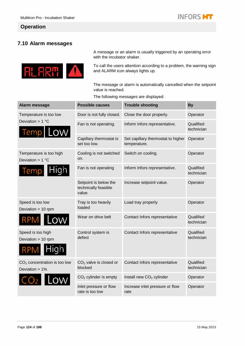
Multitron Pro - Incubation Shaker
Operation
Page 124 of 188 15 May 2013
7.10 Alarm messages A message or an alarm is usually triggered by an operating error with the incubator shaker.
To call the users attention according to a problem, the warning sign and ALARM icon always lights up.
The message or alarm is automatically cancelled when the setpoint value is reached.
The following messages are displayed:
Alarm message Possible causes Trouble shooting By
Temperature is too low Deviation > 1 °C
Door is not fully closed. Close the door properly. Operator
Fan is not operating. Inform Infors representative. Qualified technician
Capillary thermostat is set too low.
Set capillary thermostat to higher temperature.
Operator
Temperature is too high Deviation > 1 °C
Cooling is not switched on.
Switch on cooling. Operator
Fan is not operating Inform Infors representative. Qualified technician
Setpoint is below the technically feasible value.
Increase setpoint value. Operator
Speed is too low Deviation > 10 rpm
Tray is too heavily loaded
Load tray properly Operator
Wear on drive belt Contact Infors representative Qualified technician
Speed is too high Deviation > 10 rpm
Control system is defect
Contact Infors representative Qualified technician
CO2 concentration is too low Deviation > 1%
CO2 valve is closed or blocked
Contact Infors representative Qualified technician
CO2 cylinder is empty Install new CO2 cylinder Operator
Inlet pressure or flow rate is too low
Increase inlet pressure or flow rate
Operator

Multitron Pro - Incubation Shaker
Operation
15 May 2013 Page 125 of 188
CO2 concentration is too high Deviation > 1%
CO2 inlet pressure is too high
Reduce inlet pressure Operator
CO2 value is fluctuating, setpoint is not constant
Inlet pressure or flow rate is too high
Decrease inlet pressure or flow rate
Operator
Humidity is too low Deviation > 10%
Water reservoir is empty
Fill water reservoir Operator
Sterile filter (optional) is blocked, e.g. after dry-running
Exchange sterile filter Operator
Temperature is too high
Reduce the temperature setting Operator
Humidity is too high Deviation > 10%
Temperature is too low Increase the temperature setting Operator
Open door to let wet air escape. Operator
Power failure No actions required
Unit was switched off with activated parameters
No actions required
7.11 Operating the tray
CAUTION! Risk of damaging the door and the door mechanism if the opened door is subjected to a surface load of 26 kg or to a large localised load. A surface load of more than 26 kg or a large localised load on the door can damage both the door itself and the door mechanism. Therefore: – Do not place objects weighing more than 26 kg
on the door – Do not sit on the door – Do not use the door as a support

Multitron Pro - Incubation Shaker
Operation
Page 126 of 188 15 May 2013
Inserting the tray
Procedure 1. Place the tray on the glide rails of the door.
2. Load the tray or handle the flasks.
Fig. 84
3. Push the tray between the guide rails over the front stops until it meets the stops at the back of the incubation chamber.
The tray must click into place behind the front stop.
Fig. 85
4. Check whether the tray sits behind the front stop.
Closing the door lowers the tray ejectors and thus lowers the tray into the two cones. At the same time, the locking hooks move forwards to secure the tray to the table.
CAUTION! Risk of material damage if the tray is not locked. If the tray is not secured to the table by the locking mechanism, the tray can damage the chamber when the table is moving. Therefore: – Only start the unit when the tray is securely
locked to the table. 5.

Multitron Pro - Incubation Shaker
Operation
15 May 2013 Page 127 of 188
Fig. 86
6. Check whether the locking hooks are firmly securing the tray when the door is being closed
Withdrawing the tray
Procedure 1. Stop the incubator shaker.
NOTICE! The incubator shaker can be stopped either by switching off the speed rpm or by half-opening the door and waiting until the table has come to a complete stop.
2. Open the door to its full extent.
The safety mechanism automatically disengages the hooks when the door is opened and lifts the tray out of the cones at the rear.
NOTICE! If the tray cannot be pulled out, check whether the door is completely open. Press the door down to its full extent.
3. Lift the tray by the handle. 4. Pull the tray over the front stop.
5. Pull the tray over the glide rails on the opened door.
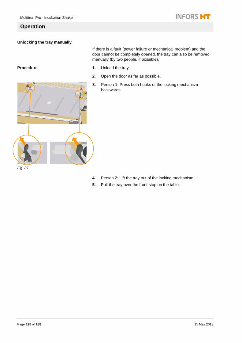
Multitron Pro - Incubation Shaker
Operation
Page 128 of 188 15 May 2013
Unlocking the tray manually If there is a fault (power failure or mechanical problem) and the door cannot be completely opened, the tray can also be removed manually (by two people, if possible).
Procedure 1. Unload the tray.
2. Open the door as far as possible.
Fig. 87
3. Person 1: Press both hooks of the locking mechanism backwards.
4. Person 2: Lift the tray out of the locking mechanism. 5. Pull the tray over the front stop on the table.

Multitron Pro - Incubation Shaker
Operation
15 May 2013 Page 129 of 188
7.12 Handling the flasks without pulling out the tray The flasks can also be handled without having to pull out the tray.
The flasks are handled as follows:
Procedure 1. Interrupt the incubator shaker (see chapter Interrupting operation)
NOTICE! The flasks can be handled when the motor has stopped and the door lock has disengaged (metallic clicking noise).
2. Open the door to a maximum of 80°.
NOTICE! The tray is disengaged when the door is opened by more than 80°.
3. Handle the flasks.
4. Close the door.
The incubator shaker automatically starts operating again with the preset parameters.
7.13 Loading the trays
CAUTION! Risk of material damage due to excessive wear resulting from uneven loading of trays. Uneven loading of trays considerably shortens the service life of the suspension mechanism and bearings of the table. Therefore: – Always place the flasks symmetrically with
respect to the centre of the tray.
The unit must be switched on when loading the table so that the safety lock on door will disengage and the door can be fully opened.

Multitron Pro - Incubation Shaker
Operation
Page 130 of 188 15 May 2013
CAUTION! Risk of material damage due to collisions between the flasks and the walls of the incubation chamber. If the flasks extend beyond the edge of the tray, they may be damaged or broken if they collide with the wall of the unit. Therefore: – Always position culture flasks on the tray so that
they do not extend beyond the edge.
Procedure 1. Open the door of the unit. 2. Pull out the tray over the glide rails up to the stops. 3. Load the tray evenly. 4. Position any optional measuring sensors.
5. Push the tray back all the way to the stop. 6. Close the door.
NOTICE! If the tray has a low load, it is advisable to place a few flasks filled with water on the tray. This will help the table to run more smoothly. The incubator shaker is designed for an average load of 12 kg. The permissible tray loads are given in the chapter "Technical Data".
NOTICE! Over the short term, heavier or lighter loading weights will not have an acute damaging effect as a result of increased wear of the incubator shaker. However, if heavier or lighter loads are to be used at high speeds over the long term please contact your INFORS representative.
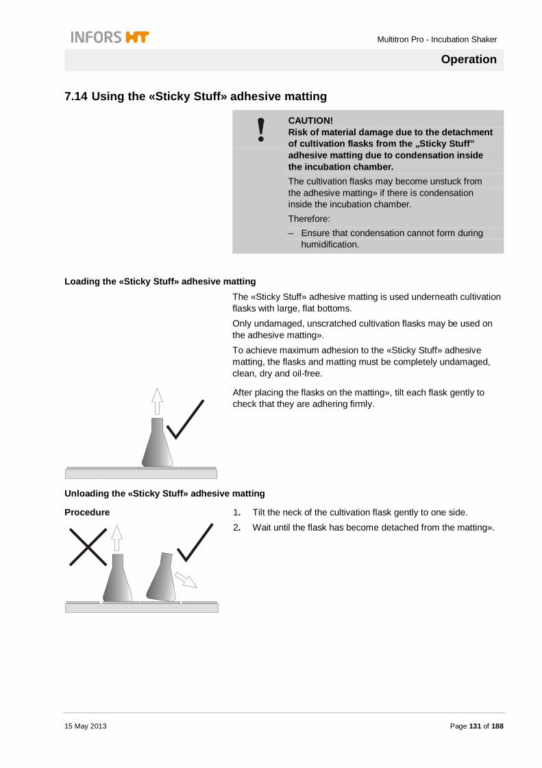
Multitron Pro - Incubation Shaker
Operation
15 May 2013 Page 131 of 188
7.14 Using the «Sticky Stuff» adhesive matting
CAUTION! Risk of material damage due to the detachment of cultivation flasks from the „Sticky Stuff” adhesive matting due to condensation inside the incubation chamber. The cultivation flasks may become unstuck from the adhesive matting» if there is condensation inside the incubation chamber. Therefore: – Ensure that condensation cannot form during
humidification.
Loading the «Sticky Stuff» adhesive matting The «Sticky Stuff» adhesive matting is used underneath cultivation flasks with large, flat bottoms. Only undamaged, unscratched cultivation flasks may be used on the adhesive matting». To achieve maximum adhesion to the «Sticky Stuff» adhesive matting, the flasks and matting must be completely undamaged, clean, dry and oil-free.
After placing the flasks on the matting», tilt each flask gently to check that they are adhering firmly.
Unloading the «Sticky Stuff» adhesive matting
Procedure
1. Tilt the neck of the cultivation flask gently to one side. 2. Wait until the flask has become detached from the matting».

Multitron Pro - Incubation Shaker
Operation
Page 132 of 188 15 May 2013
NOTICE! Large flasks may take 20 to 30 seconds to become detached.
Very firmly attached flasks can be detached as follows:
Procedure
1. Use a syringe to squirt a few drops of water onto the edge of the cultivation flask.
2. Tilt the neck of the cultivation flask gently to one side.
NOTICE! Under certain circumstances, Fernbach flasks may be difficult to detach from the adhesive matting. To facilitate removal, part of the adhesive matting can be covered with the supplied protective film.
7.15 Interrupting operation The unit can be stopped by opening the door. All functions and parameters remain activated. The door can only be fully opened once the table has stopped moving.
NOTICE! The door must be held half open while the table is slowing down. The door lock is only disengaged once the table has stopped moving, provided that the door is not subjected to a load (e.g. by something resting on it).
To reduce operating costs, all parameters are deactivated while the door is open. When the door is shut, the unit restarts at a closing angle of 45° with the preset parameters and with the interior light switched on for 1 minute for inspection purposes.

Multitron Pro - Incubation Shaker
Operation
15 May 2013 Page 133 of 188
7.16 Operating the UV sterilisation
Fig. 88
The push-button switch for the UV sterilisation lamps is located on the left-hand side wall.
UV sterilisation OFF – push-button switch is not illuminated UV sterilisation ON – push-button switch is illuminated
7.17 Operating the Direct Steam Humidification
NOTICE! The cooling system switches off automatically when the direct steam humidification is switched on!
The Direct Steam Humidification is switched on using the operating panel.
Procedure
1. Press the option key to select the illumination parameter.
Parameter sign and unit light up.
2. Press SET key.
3. Press PLUS or MINUS key to set value.
4. Press ON/OFF key to switch parameter on.

Multitron Pro - Incubation Shaker
Operation
Page 134 of 188 15 May 2013
Display show ON and changes to the current value of the parameter, e.g. 65%.
NOTICE! A setpoint of 70% rH is sufficient to prevent evaporation. Under ideal conditions, a setpoint of 85% rH can be used.
NOTICE! Formation of condensation indicates that the maximum humidity has been reached. The setpoint value must be reduced.
7.18 Operating the cooling system Top-mounted cooling system 900 watts / 1200 watts
The cooling system has its own power supply. The cooling system is switched on with the green push-button on the left-hand side of the cooling module. The push-button lights up when the cooling system is switched on.
Side-mounted cooling system 380 watts The incubation shaker supplies power to this cooling system. The cooling system is ready for operation when the incubation shaker is switched on.
External cooling system The external cooling system is supplied via a pressurised line from the in-house cooling system. The external cooling system is ready for operation when the incubation shaker is switched on.

Multitron Pro - Incubation Shaker
Operation
15 May 2013 Page 135 of 188
Activating the cooling parameter The incubation chamber can be cooled as follows:
Procedure
1. Press option key to select parameter.
Temperature sign lights up.
2. Press SET key.
3. Press PLUS or MINUS key to set setpoint.
4. Press ON/OFF key to switch parameter on.
The upper display shows ON and then the current value of the parameter, e.g. 18.5 °C.
7.19 Starting illumination The illumination is switched on using the operating panel. This requires that the switches for the individual pairs of tubes are turned on.
NOTICE! The fluorescent tubes generate heat during operation. Therefore, always switch on the cooling system when the illumination is switched on.
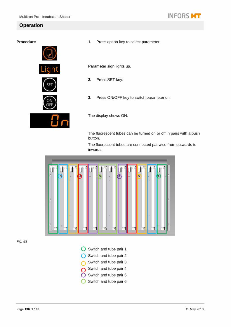
Multitron Pro - Incubation Shaker
Operation
Page 136 of 188 15 May 2013
Procedure
1. Press option key to select parameter.
Parameter sign lights up.
2. Press SET key.
3. Press ON/OFF key to switch parameter on.
The display shows ON.
The fluorescent tubes can be turned on or off in pairs with a push button. The fluorescent tubes are connected pairwise from outwards to inwards.
Fig. 89
Switch and tube pair 1
Switch and tube pair 2 Switch and tube pair 3 Switch and tube pair 4
Switch and tube pair 5 Switch and tube pair 6
Multitron Pro - Incubation Shaker
Operation
15 May 2013 Page 137 of 188
7.20 Starting algae illumination The illumination is switched on using the operating panel.
Procedure
1. Press option key to select parameter illumination.
Parameter sign „Light“ lights up.
2. Press SET key.
3. Press ON/OFF key to switch parameter on.
Display shows ON.
4. Set the light intensity with the rotary knob.
7.21 Operating the CO2 gassing system
NOTICE! To prevent excessive consumption of gas, the door, drain hole and path-through (optional) of the incubation shaker must be closed.
NOTICE! The CO2 gassing system only works correctly when the temperature control system is switched on.
Multitron Pro - Incubation Shaker
Operation
Page 138 of 188 15 May 2013
Set the CO2 gassing system as follows:
Procedure
1. Press option key to select parameter CO2.
Parameter sign and unit light up.
2. Press SET key.
3. Press PLUS or MINUS key to change setpoint.
4. Press ON/OFF key to switch on parameter.
Display shows current value (e.g. 5.0%).
Using the safety curtain
The safety curtain is attached to the ceiling of the incubation chamber with four snap fasteners.
NOTICE! The label „Outside“ must face outwards.
Fig. 90
Detaching the safety curtain Undo each snap fastener with a gentle tug. Attaching the safety curtain Gently press the two halves of the snap fastener together, one by one.
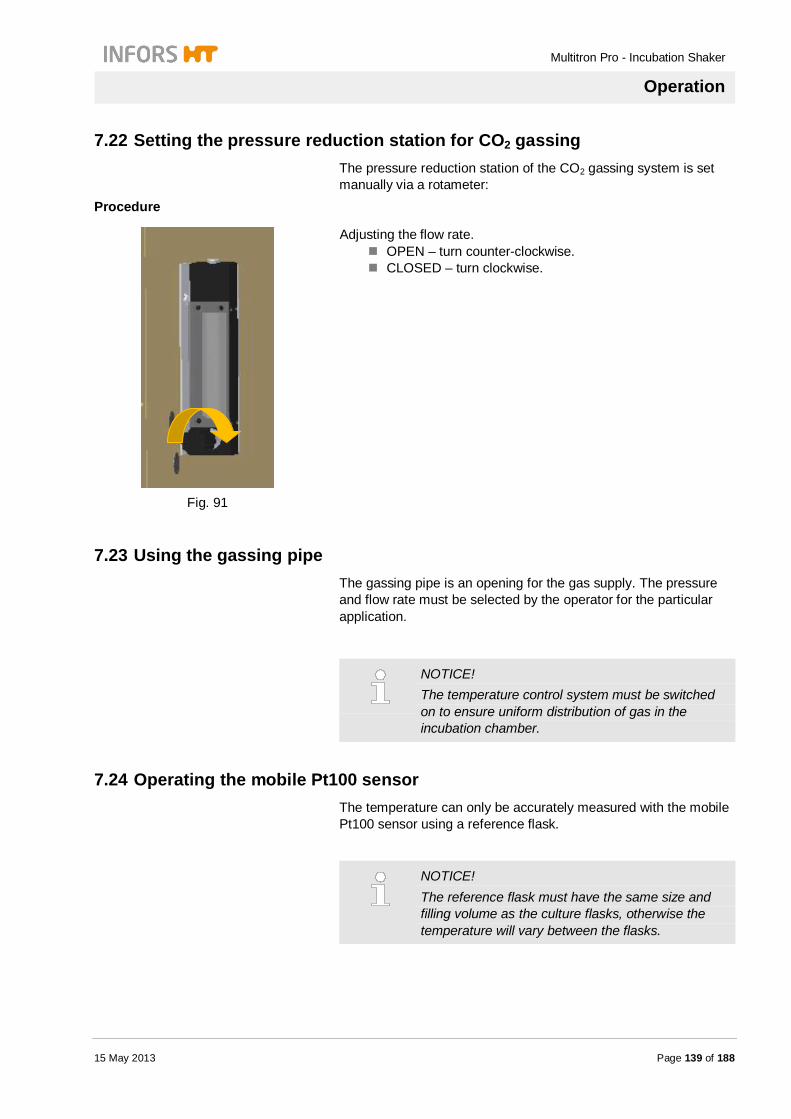
Multitron Pro - Incubation Shaker
Operation
15 May 2013 Page 139 of 188
7.22 Setting the pressure reduction station for CO2 gassing The pressure reduction station of the CO2 gassing system is set manually via a rotameter:
Procedure
Fig. 91
Adjusting the flow rate. OPEN – turn counter-clockwise. CLOSED – turn clockwise.
7.23 Using the gassing pipe The gassing pipe is an opening for the gas supply. The pressure and flow rate must be selected by the operator for the particular application.
NOTICE! The temperature control system must be switched on to ensure uniform distribution of gas in the incubation chamber.
7.24 Operating the mobile Pt100 sensor The temperature can only be accurately measured with the mobile Pt100 sensor using a reference flask.
NOTICE! The reference flask must have the same size and filling volume as the culture flasks, otherwise the temperature will vary between the flasks.
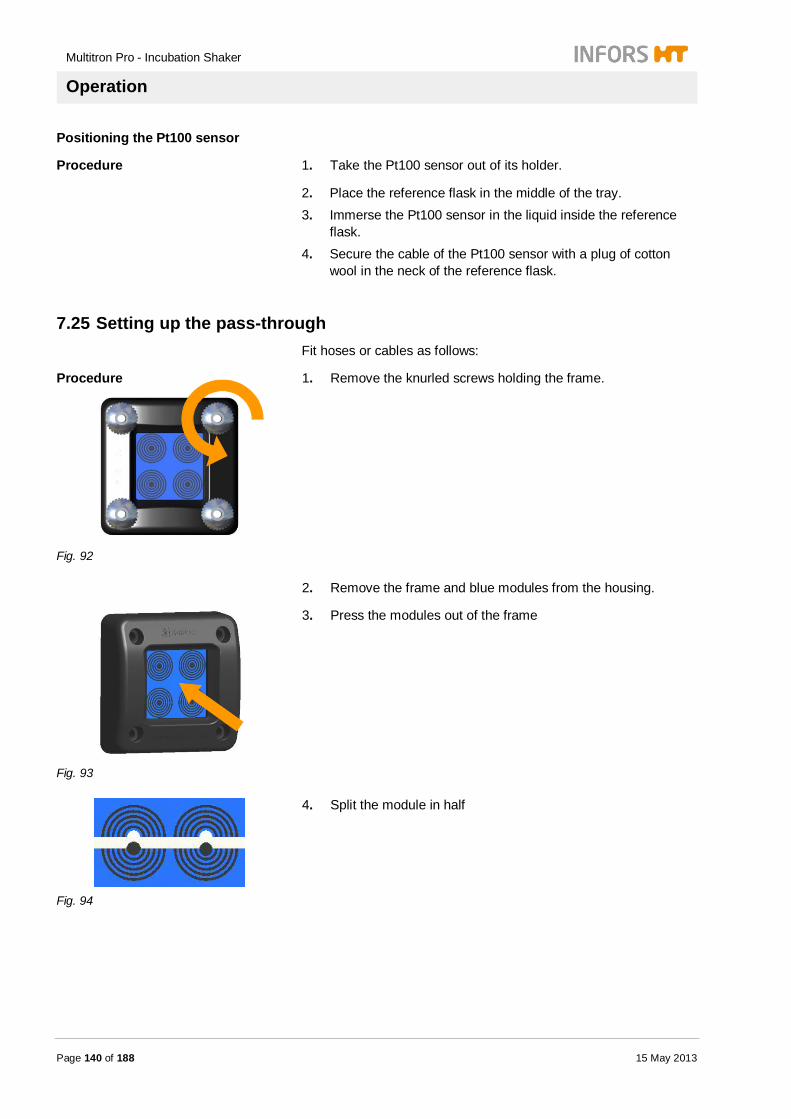
Multitron Pro - Incubation Shaker
Operation
Page 140 of 188 15 May 2013
Positioning the Pt100 sensor
Procedure 1. Take the Pt100 sensor out of its holder.
2. Place the reference flask in the middle of the tray. 3. Immerse the Pt100 sensor in the liquid inside the reference
flask. 4. Secure the cable of the Pt100 sensor with a plug of cotton
wool in the neck of the reference flask.
7.25 Setting up the pass-through Fit hoses or cables as follows:
Procedure
Fig. 92
1. Remove the knurled screws holding the frame.
2. Remove the frame and blue modules from the housing.
Fig. 93
3. Press the modules out of the frame
Fig. 94
4. Split the module in half
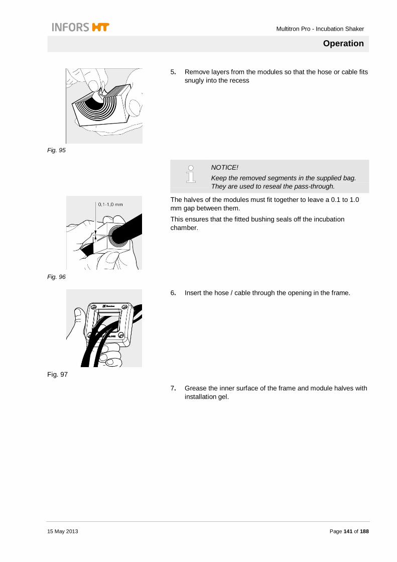
Multitron Pro - Incubation Shaker
Operation
15 May 2013 Page 141 of 188
Fig. 95
5. Remove layers from the modules so that the hose or cable fits snugly into the recess
NOTICE! Keep the removed segments in the supplied bag. They are used to reseal the pass-through.
Fig. 96
The halves of the modules must fit together to leave a 0.1 to 1.0 mm gap between them. This ensures that the fitted bushing seals off the incubation chamber.
Fig. 97
6. Insert the hose / cable through the opening in the frame.
7. Grease the inner surface of the frame and module halves with installation gel.

Multitron Pro - Incubation Shaker
Operation
Page 142 of 188 15 May 2013
Fig. 98
8. Secure the hose / cable in the module halves. 9. Press the modules back into the frame.
10. Insert the hose / cable through the opening in the housing.
Fig. 99
11. Secure the frame to the housing with the knurled screws.
CAUTION! Risk of material damage due to abrasion and trapping of hoses and cables. Hoses and cables may be damaged if they are trapped during shaking or if they are chafed by parts inside the chamber. Therefore: – Position cables and hoses so that they cannot
come into contact with anything.
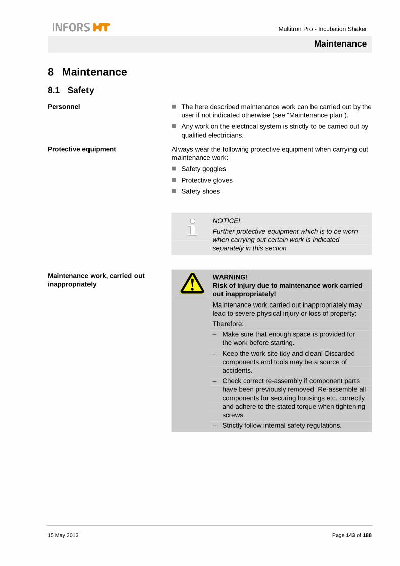
Multitron Pro - Incubation Shaker
Maintenance
15 May 2013 Page 143 of 188
8 Maintenance
8.1 Safety
Personnel The here described maintenance work can be carried out by the user if not indicated otherwise (see “Maintenance plan”).
Any work on the electrical system is strictly to be carried out by qualified electricians.
Protective equipment Always wear the following protective equipment when carrying out maintenance work:
Safety goggles Protective gloves Safety shoes
NOTICE! Further protective equipment which is to be worn when carrying out certain work is indicated separately in this section
Maintenance work, carried out inappropriately
WARNING! Risk of injury due to maintenance work carried out inappropriately! Maintenance work carried out inappropriately may lead to severe physical injury or loss of property: Therefore: – Make sure that enough space is provided for
the work before starting. – Keep the work site tidy and clean! Discarded
components and tools may be a source of accidents.
– Check correct re-assembly if component parts have been previously removed. Re-assemble all components for securing housings etc. correctly and adhere to the stated torque when tightening screws.
– Strictly follow internal safety regulations.
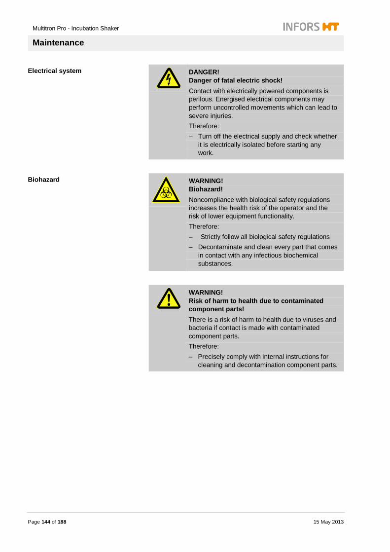
Multitron Pro - Incubation Shaker
Maintenance
Page 144 of 188 15 May 2013
Electrical system
DANGER! Danger of fatal electric shock! Contact with electrically powered components is perilous. Energised electrical components may perform uncontrolled movements which can lead to severe injuries. Therefore: – Turn off the electrical supply and check whether
it is electrically isolated before starting any work.
Biohazard
WARNING! Biohazard! Noncompliance with biological safety regulations increases the health risk of the operator and the risk of lower equipment functionality. Therefore: – Strictly follow all biological safety regulations – Decontaminate and clean every part that comes
in contact with any infectious biochemical substances.
WARNING! Risk of harm to health due to contaminated component parts! There is a risk of harm to health due to viruses and bacteria if contact is made with contaminated component parts. Therefore: – Precisely comply with internal instructions for
cleaning and decontamination component parts.
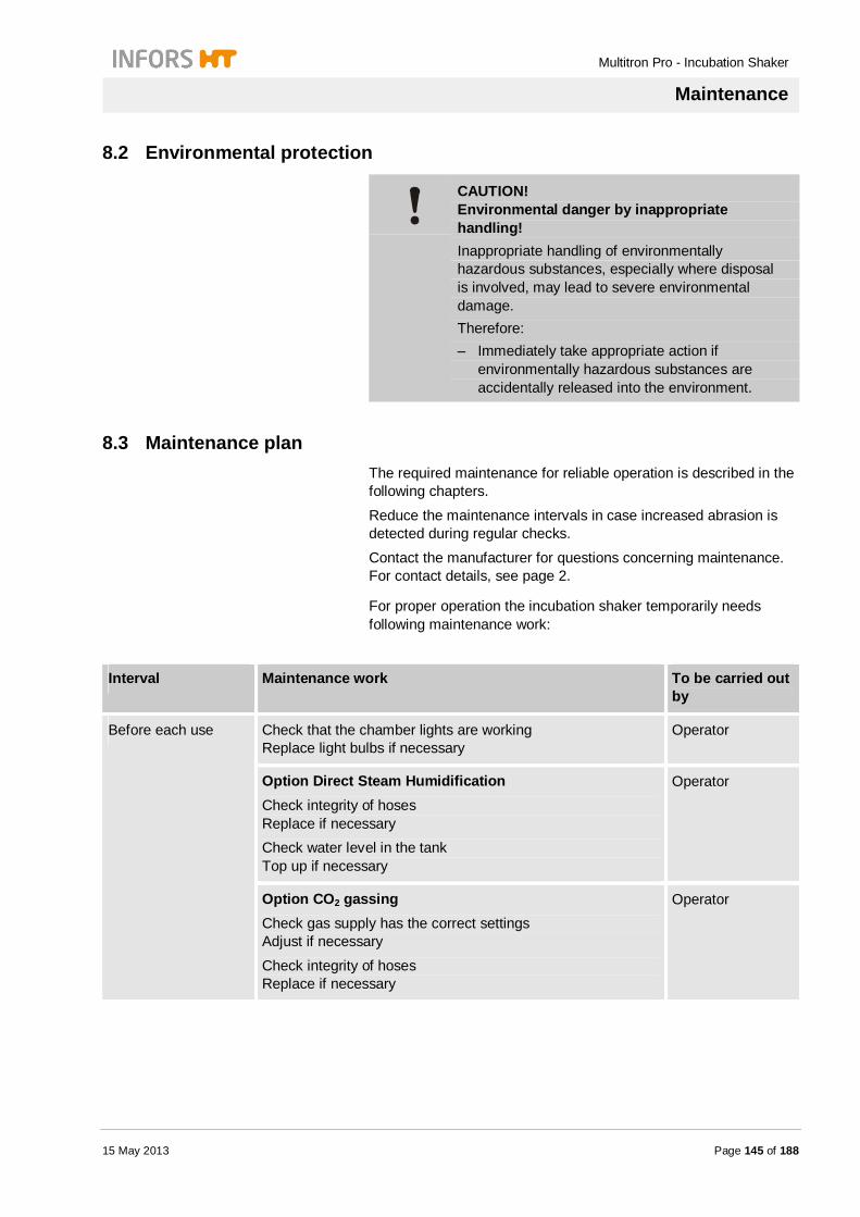
Multitron Pro - Incubation Shaker
Maintenance
15 May 2013 Page 145 of 188
8.2 Environmental protection
CAUTION! Environmental danger by inappropriate handling! Inappropriate handling of environmentally hazardous substances, especially where disposal is involved, may lead to severe environmental damage. Therefore: – Immediately take appropriate action if
environmentally hazardous substances are accidentally released into the environment.
8.3 Maintenance plan The required maintenance for reliable operation is described in the following chapters.
Reduce the maintenance intervals in case increased abrasion is detected during regular checks.
Contact the manufacturer for questions concerning maintenance. For contact details, see page 2.
For proper operation the incubation shaker temporarily needs following maintenance work:
Interval Maintenance work To be carried out by
Before each use Check that the chamber lights are working Replace light bulbs if necessary
Operator
Option Direct Steam Humidification Check integrity of hoses Replace if necessary Check water level in the tank Top up if necessary
Operator
Option CO2 gassing Check gas supply has the correct settings Adjust if necessary
Check integrity of hoses Replace if necessary
Operator

Multitron Pro - Incubation Shaker
Maintenance
Page 146 of 188 15 May 2013
Option Illumination Check fluorescent tubes and starter are working correctly Replace if necessary
Operator
Option Illumination „Algae“ Check fluorescent tubes and starter are working correctly Replace if necessary
Qualified technician
Once a year Option Sterilisation of air supply Replace UV-Sterilisation lamps (Life cycle 8000 operating hours)
Qualified technician
Option Cooling System Check the cooling liquid level in the tank Top up if necessary
Qualified technician
Calibrate measuring devices Qualified technician
Every 3 years Option Cooling System Replace cooling liquid of top / bottom cooling
Qualified technician
As required Disinfect unit Operator
Option «Sticky Stuff» Clean «Sticky Stuff» adhesive matting
Operator
Option «Sticky Stuff» Replace «Sticky Stuff» adhesive matting
Operator
Clean unit Operator
Test alarm functions Operator
Option Cooling System Clean heat exchanger of top cooling
Qualified technician
Option Cooling System Clean heat exchanger of side cooling
Operator
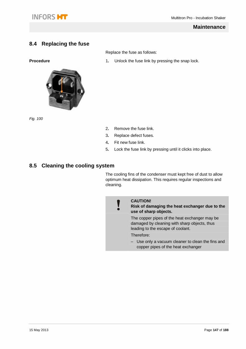
Multitron Pro - Incubation Shaker
Maintenance
15 May 2013 Page 147 of 188
8.4 Replacing the fuse Replace the fuse as follows:
Procedure
Fig. 100
1. Unlock the fuse link by pressing the snap lock.
2. Remove the fuse link. 3. Replace defect fuses.
4. Fit new fuse link. 5. Lock the fuse link by pressing until it clicks into place.
8.5 Cleaning the cooling system The cooling fins of the condenser must kept free of dust to allow optimum heat dissipation. This requires regular inspections and cleaning.
CAUTION! Risk of damaging the heat exchanger due to the use of sharp objects. The copper pipes of the heat exchanger may be damaged by cleaning with sharp objects, thus leading to the escape of coolant. Therefore: – Use only a vacuum cleaner to clean the fins and
copper pipes of the heat exchanger

Multitron Pro - Incubation Shaker
Maintenance
Page 148 of 188 15 May 2013
Side-mounted cooling system
Procedure
Fig. 101
1. Remove the screws holding the grating.
2. Lift off the grating.
3. Clean the fins with a vacuum cleaner. 4. Reattach the grating with the two screws.
Top-mounted cooling system
Procedure
Fig. 102
1. Visually inspect the heat exchanger of the top-mounted cooling system for dust.
2. If there is a lot of dust, contact the manufacturer's service center.
Coolant
Maintenance of the coolant system must be carried out by the manufacturer's service center.
Annual check of the coolant level. Replacement of the coolant every 3 years.
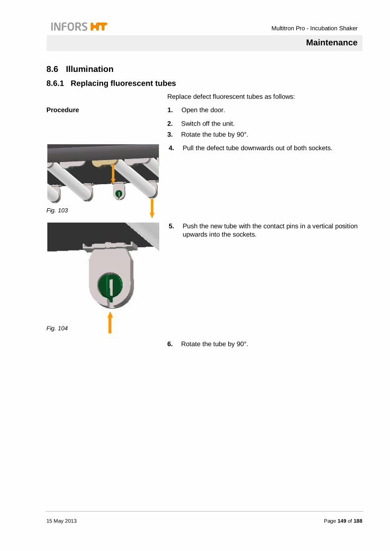
Multitron Pro - Incubation Shaker
Maintenance
15 May 2013 Page 149 of 188
8.6 Illumination 8.6.1 Replacing fluorescent tubes
Replace defect fluorescent tubes as follows:
Procedure 1. Open the door.
2. Switch off the unit. 3. Rotate the tube by 90°.
Fig. 103
4. Pull the defect tube downwards out of both sockets.
Fig. 104
5. Push the new tube with the contact pins in a vertical position upwards into the sockets.
6. Rotate the tube by 90°.

Multitron Pro - Incubation Shaker
Maintenance
Page 150 of 188 15 May 2013
8.6.2 Replacing the starter
Fig. 105
The starters are located on the left-hand side of the front lamp sockets.
Procedure 1. Open the door.
2. Switch off the unit.
3. Remove the defect starter out of its socket by rotating it by 90° anti-clockwise.
4. Fit the new starter into the socket by rotating it clockwise.
NOTICE! Fluorescent tubes contain mercury. Dispose of fluorescent tubes according to the local statutory regulations.
8.7 Cleaning the algae illumination Clean the Plexiglas panel and the tubes as follows:
Procedure 1. Open the door.
2. Switch off the unit and disconnect it from the power supply.
Fig. 106
3. Hold onto the front edge of the Plexiglas panel with both hands and pull it downwards uniformly off the tubes.
4. Clean the Plexiglas panel with a soft cloth and a mild household cleaner.
5. Clean the tubes with a soft cloth and a mild household cleaner.
6. Replace the Plexiglas panel with the clips by pressing it gently onto the tubes.

Multitron Pro - Incubation Shaker
Maintenance
15 May 2013 Page 151 of 188
8.8 Replacing the feed hose of the Direct Steam Humidification Replacing the feed hose
Replace a damaged feed hose of the Direct Steam Humidification as follows:
Procedure
Fig. 107
1. Keeping the O-ring pressed down, pull the hose out of the connector.
2. Push the new hose into the connector (the O-ring does not need to be pressed).
8.9 Replacing the «Sticky Stuff» adhesive matting
NOTICE! Regular disinfection may reduce the adhesiveness of the «Sticky Stuff» matting.
Replace the adhesive matting as follows:
Procedure
0
1. Release the adhesive matting on one side of the tray and then pull upwards at an angle.
2. Degrease the tray with acetone. 3. Thoroughly moisten the tray with water.
4. Wet the new matting and place on the tray (see the installation instructions for «Sticky Stuff»).
Multitron Pro - Incubation Shaker
Maintenance
Page 152 of 188 15 May 2013
8.10 Cleaning
8.11 Cleaning the glass door pane
CAUTION! Risk of material damage due to use of inapplicable cleaning utensils! Abrasive cleaning utensils, as sponges, cleaning rags, will scratch the safety glass. The breaking and shock resistance will be heavily reduced by micro-scratches! Therefore: – Clean glass door pane only with a soft cleaning
rag.
Clean inside and outside of the glass door pane with a soft cleaning rag and mild detergent.
The following areas of the incubator shaker must be cleaned regularly:
Housing Chamber Floor pan
Trays Cooling systems
CAUTION! Risk of material damage if the incubation chamber is not cleaned sufficiently. Moulds or other microorganisms may grow uncontrollably and thus jeopardise successful cultivation and the health of the operator. Therefore: – If a flask has broken or culture medium has
escaped, clean the chamber thoroughly with a neutral household cleaner.
– Clean with standard disinfectants, if necessary.
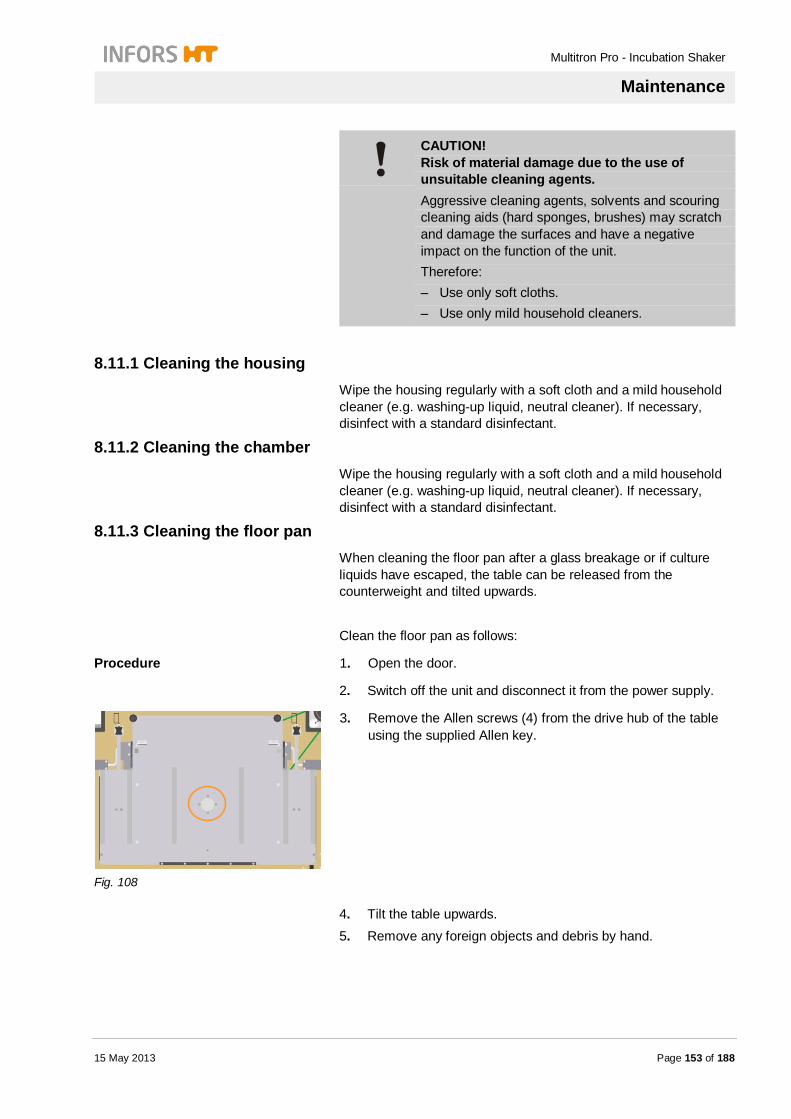
Multitron Pro - Incubation Shaker
Maintenance
15 May 2013 Page 153 of 188
CAUTION! Risk of material damage due to the use of unsuitable cleaning agents. Aggressive cleaning agents, solvents and scouring cleaning aids (hard sponges, brushes) may scratch and damage the surfaces and have a negative impact on the function of the unit. Therefore: – Use only soft cloths. – Use only mild household cleaners.
8.11.1 Cleaning the housing Wipe the housing regularly with a soft cloth and a mild household cleaner (e.g. washing-up liquid, neutral cleaner). If necessary, disinfect with a standard disinfectant.
8.11.2 Cleaning the chamber Wipe the housing regularly with a soft cloth and a mild household cleaner (e.g. washing-up liquid, neutral cleaner). If necessary, disinfect with a standard disinfectant.
8.11.3 Cleaning the floor pan When cleaning the floor pan after a glass breakage or if culture liquids have escaped, the table can be released from the counterweight and tilted upwards.
Clean the floor pan as follows:
Procedure 1. Open the door.
2. Switch off the unit and disconnect it from the power supply.
Fig. 108
3. Remove the Allen screws (4) from the drive hub of the table using the supplied Allen key.
4. Tilt the table upwards. 5. Remove any foreign objects and debris by hand.
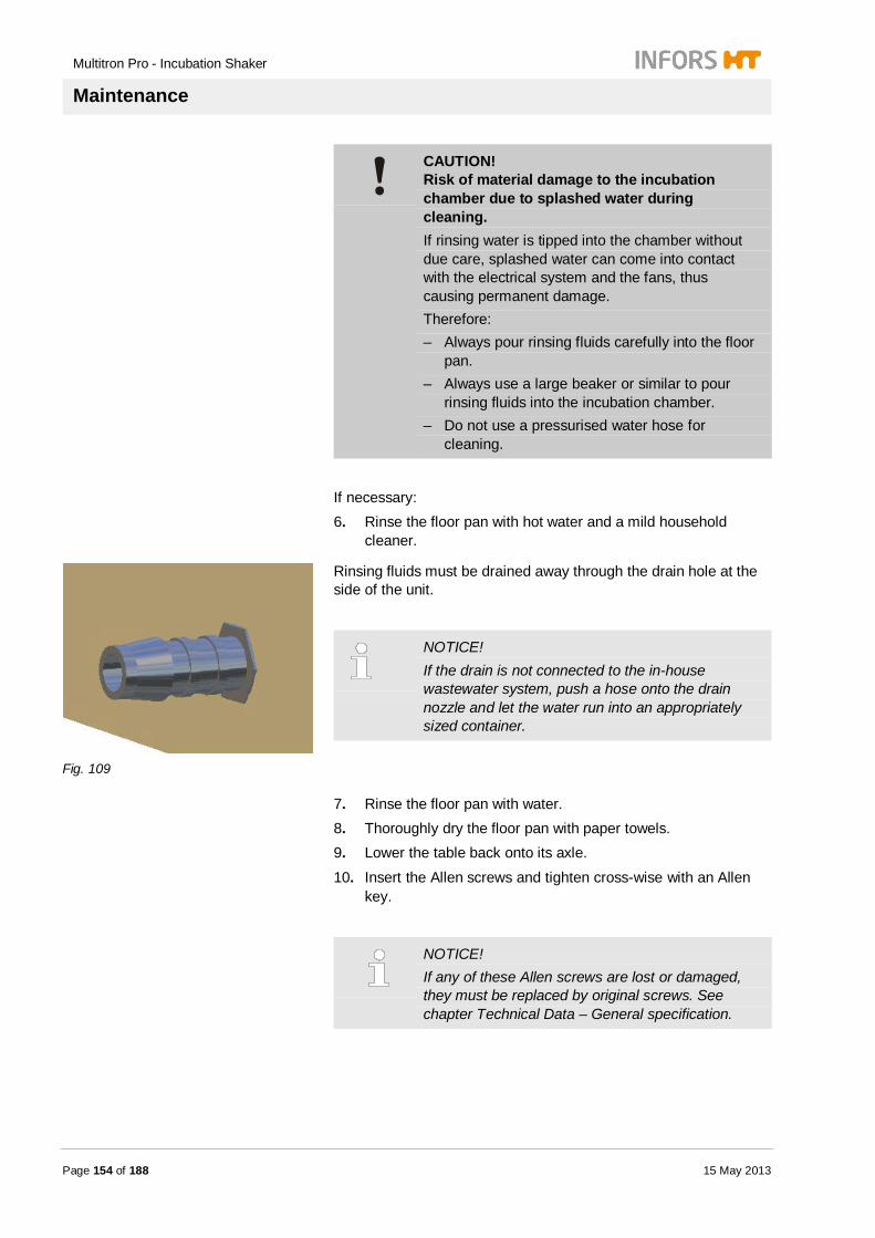
Multitron Pro - Incubation Shaker
Maintenance
Page 154 of 188 15 May 2013
CAUTION! Risk of material damage to the incubation chamber due to splashed water during cleaning. If rinsing water is tipped into the chamber without due care, splashed water can come into contact with the electrical system and the fans, thus causing permanent damage. Therefore: – Always pour rinsing fluids carefully into the floor
pan. – Always use a large beaker or similar to pour
rinsing fluids into the incubation chamber. – Do not use a pressurised water hose for
cleaning.
If necessary: 6. Rinse the floor pan with hot water and a mild household
cleaner.
Fig. 109
Rinsing fluids must be drained away through the drain hole at the side of the unit.
NOTICE! If the drain is not connected to the in-house wastewater system, push a hose onto the drain nozzle and let the water run into an appropriately sized container.
7. Rinse the floor pan with water. 8. Thoroughly dry the floor pan with paper towels. 9. Lower the table back onto its axle.
10. Insert the Allen screws and tighten cross-wise with an Allen key.
NOTICE! If any of these Allen screws are lost or damaged, they must be replaced by original screws. See chapter Technical Data – General specification.

Multitron Pro - Incubation Shaker
Maintenance
15 May 2013 Page 155 of 188
8.11.4 Cleaning the trays Regularly wipe the trays and their mounted parts (rails, clips, adhesive matting, etc.) with a soft cloth and a mild household cleaner (e.g. washing-up liquid, neutral cleaner). If necessary, disinfect with a standard disinfectant.
8.12 Cleaning the «Sticky Stuff» adhesive matting The adhesiveness of the mats declines over time due to dust and soiling.
Regenerate the adhesive mats as follows: Scrub the surfaces vigorously with a scouring pad and clean
warm water or mild soapy water (washing-up liquid). Allow to dry overnight.
Disinfect with quaternary ammonium compounds.
CAUTION! Risk of material damage due to the use of solvent-based cleaning agents. The structure and adhesive properties of the «Sticky Stuff» adhesive matting can be destroyed by solvent-based cleaners. Risk of detachment of cultivation flasks from the «Sticky Stuff» adhesive matting during operation of the shaker. Therefore: – Use only a mild neutral cleaning agent (e.g.
washing-up liquid) – Use only quaternary ammonium compounds for
disinfection
See also the enclosed brief instructions for the «Sticky Stuff» adhesive matting.
NOTICE! If the adhesiveness of the matting» cannot be restored by cleaning, it must be replaced. Please refer to the chapter "Maintenance – Replacing the «Sticky Stuff» adhesive matting".

Multitron Pro - Incubation Shaker
Maintenance
Page 156 of 188 15 May 2013
8.13 CO2 curtain Clean the CO2 curtain as follows:
Procedure 1. Detach the CO2 curtain in the incubation chamber.
2. Clean the surface with a soft cloth and mild cleaner (washing-up liquid, neutral cleaner).
3. If necessary, disinfect with a standard disinfectant.
8.14 Finishing maintenance work
WARNING! Risk of injury! If protective devices on the equipment are not brought back to their original state after maintenance work, this carries a substantial risk of injury at the next time of operation. Therefore: – Always restore all protective devices on the
equipment back to their original state after finishing maintenance work.

Multitron Pro - Incubation Shaker
Interferences
15 May 2013 Page 157 of 188
9 Interferences
Possible reasons for interference or a problem and how to resolve it is described in the following section.
Reduce the service intervals if interferences/problems become increasingly common.
Contact the manufacturer in case of developing problems which cannot be resolved by following the above mentioned instructions. For service contact details, see page 2.
Action in case of interferences The following instructions are to be followed: 1. Immediately switch off the equipment and unplug the mains
plug in case of malfunctions which represent an imminent danger to persons or property.
NOTICE! Instructions given by in-house safety protocols are to be followed if additional isolation switches for the power supply have been installed locally.
2. Investigate the cause of the malfunction.
3. Inform a responsible person about the malfunction/trouble. 4. Depending on the type of malfunction, solve the problem or
engage authorised qualified personnel to do so.
NOTICE! The following trouble shooting guide clearly indicates who is authorised to solve the problems described.
Multitron Pro - Incubation Shaker
Interferences
Page 158 of 188 15 May 2013
Action in case of interferences of incubation shaker
WARNING! If people and/or equipment are in danger, switch off the incubator shaker immediately and disconnect it from the power supply.
Switch off the unit if the following irregularities occur:
Loud noises Smoke Odor
Strong vibrations After switching off and disconnecting from the power supply, proceed as follows:
Procedure 1. Avert danger.
2. Remove flasks manually from the tray.
NOTICE! If the incubator shaker is switched off, the tray cannot be removed because the door lock cannot be disengaged.
3. Remove the tray manually (see chapter "Operation –
Operating the tray").
NOTICE! If the cultivation flasks cannot be removed or if the incubator shaker needs repairing, contact your INFORS representative. (See page 2 for addresses)

Multitron Pro - Incubation Shaker
Interferences
15 May 2013 Page 159 of 188
9.1 Safety
Personnel The here described trouble shooting work may be carried out by the user, if not indicated otherwise (see “Tables of Interferences”).
Any work on the electrical system is strictly to be carried out by qualified electricians.
Electrical system
DANGER! Danger of fatal electric shock! Contact with electrically powered components is perilous. Energised electrical components may perform uncontrolled movements which can lead to severe injuries. Therefore: – Turn off the electrical supply and check whether
it is electrically isolated before starting any work.
WARNING! Risk of injury due to inappropriate trouble shooting! Inappropriate trouble shooting may lead to severe physical injury or loss of property. Therefore: – Strictly follow the trouble shooting instructions
stated in this operating manual

Multitron Pro - Incubation Shaker
Interferences
Page 160 of 188 15 May 2013
9.2 Tables of interferences
9.3 Error messages Error messages are triggered by a mechanical or elctronical interference on the equipment.
To additionally draw attention of the user, an interference is displayed with the warning sign and the ERROR symbol.
The error messages disappear, when the interference was remedied.
General interference
Interferences Possible causes Trouble shooting By
Door cannot be fully opened Door is subjected to a load
Close the door and open again Operator
Unit is switched off Switch the unit on Operator
Tray lock does not engage A foreign body is blocking the locking system
Remove foreign body Operator
Foreign body is under the table
Detach table from its axle, tilt it upwards and remove the foreign body.
Operator
Tray is bent or damaged
Replace the tray Operator
Tray is not being released Door is not fully open.
Press the door downwards to its lowest position
Operator
Status display is not illuminated
Unit is switched off Switch the unit on Operator
Power plug has been disconnected
Connect the power plug Operator
Fuse has blown Replace fuse Operator
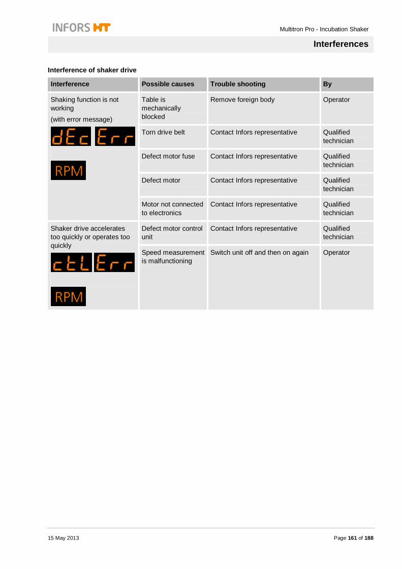
Multitron Pro - Incubation Shaker
Interferences
15 May 2013 Page 161 of 188
Interference of shaker drive
Interference Possible causes Trouble shooting By
Shaking function is not working (with error message)
Table is mechanically blocked
Remove foreign body Operator
Torn drive belt Contact Infors representative Qualified technician
Defect motor fuse Contact Infors representative Qualified technician
Defect motor Contact Infors representative Qualified technician
Motor not connected to electronics
Contact Infors representative Qualified technician
Shaker drive accelerates too quickly or operates too quickly
Defect motor control unit
Contact Infors representative Qualified technician
Speed measurement is malfunctioning
Switch unit off and then on again Operator
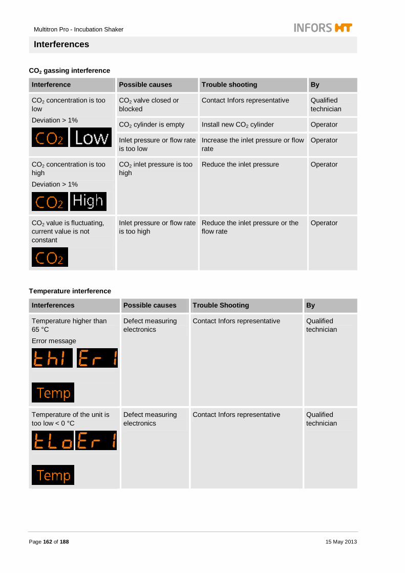
Multitron Pro - Incubation Shaker
Interferences
Page 162 of 188 15 May 2013
CO2 gassing interference
Interference Possible causes Trouble shooting By
CO2 concentration is too low Deviation > 1%
CO2 valve closed or blocked
Contact Infors representative Qualified technician
CO2 cylinder is empty Install new CO2 cylinder Operator
Inlet pressure or flow rate is too low
Increase the inlet pressure or flow rate
Operator
CO2 concentration is too high
Deviation > 1%
CO2 inlet pressure is too high
Reduce the inlet pressure Operator
CO2 value is fluctuating, current value is not constant
Inlet pressure or flow rate is too high
Reduce the inlet pressure or the flow rate
Operator
Temperature interference
Interferences Possible causes Trouble Shooting By
Temperature higher than 65 °C
Error message
Defect measuring electronics
Contact Infors representative Qualified technician
Temperature of the unit is too low < 0 °C
Defect measuring electronics
Contact Infors representative Qualified technician

Multitron Pro - Incubation Shaker
Interferences
15 May 2013 Page 163 of 188
No value on temperature display
Pt100 sensor or sensor cable is defect
Contact Infors representative Qualified technician
Temperature in flask with mobile Pt100 is too high (> 65 °C)
Defect measuring electronics
Contact Infors representative Qualified technician
Temperature in flask with mobile Pt100 is too low (< 0 °C)
Defect measuring electronics
Contact Infors representative Qualified technician
No value on temperature display
Pt100 sensor or sensor cable is defect
Contact Infors representative Qualified technician
Temperature too high. No error message
Cooling is not switched on
Switch on cooling Operator
No power supply to cooling system
Check fuse of cooling system, replace if necessary
Operator
Connect unit to power supply Operator

Multitron Pro - Incubation Shaker
Interferences
Page 164 of 188 15 May 2013
Temperature is not reaching the desired value
Heating is not switched on
Activate the temperature parameter Operator
Setpoint value is too low
Increase setpoint value Operator
Capillary thermostat is set too low (must be at least 10 °C above the setpoint value)
Set capillary thermostat to higher temperature
Operator
Heating fan is not working
Contact Infors representative Qualified technician
Door is not completely closed
Close the door properly Operator
Top-mounted cooling: cooling fins are dusty
Contact Infors representative Qualified technician
Side-mounted cooling: cooling fins are dusty
Clean cooling fins Operator

Multitron Pro - Incubation Shaker
Interferences
15 May 2013 Page 165 of 188
Humidity interference
Interference Possible causes Trouble shooting By
Water supply to the Direct Steam Humidification is interrupted; humidity parameter has been automatically deactivated.
Water reservoir is empty
Fill water reservoir Operator
Air pocket between wet filter and reservoir
Replace wet filter with a dry one Operator
Valve is defect Contact Infors representative Qualified technician
Transmission error of the humidity sensor or the temperature sensor
Restart software (switch unit OFF and then ON)
Operator
Steam generator is defect
Contact Infors representative Qualified technician
Inlet pressure is too high
Reduce inlet pressure (max. 0.3 bars)
Operator
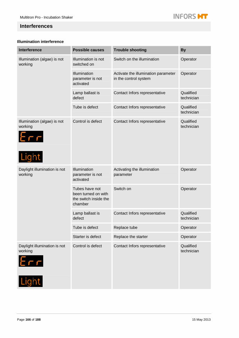
Multitron Pro - Incubation Shaker
Interferences
Page 166 of 188 15 May 2013
Illumination interference
Interference Possible causes Trouble shooting By
Illumination (algae) is not working
Illumination is not switched on
Switch on the illumination Operator
Illumination parameter is not activated
Activate the illumination parameter in the control system
Operator
Lamp ballast is defect
Contact Infors representative Qualified technician
Tube is defect Contact Infors representative Qualified technician
Illumination (algae) is not working
Control is defect Contact Infors representative Qualified technician
Daylight illumination is not working
Illumination parameter is not activated
Activating the illumination parameter
Operator
Tubes have not been turned on with the switch inside the chamber
Switch on Operator
Lamp ballast is defect
Contact Infors representative Qualified technician
Tube is defect Replace tube Operator
Starter is defect Replace the starter Operator
Daylight illumination is not working
Control is defect Contact Infors representative Qualified technician
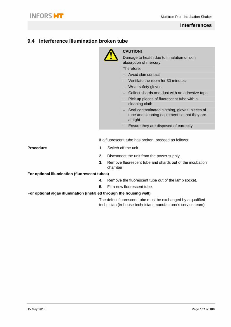
Multitron Pro - Incubation Shaker
Interferences
15 May 2013 Page 167 of 188
9.4 Interference Illumination broken tube
CAUTION! Damage to health due to inhalation or skin absorption of mercury. Therefore: – Avoid skin contact – Ventilate the room for 30 minutes – Wear safety gloves – Collect shards and dust with an adhesive tape – Pick up pieces of fluorescent tube with a
cleaning cloth – Seal contaminated clothing, gloves, pieces of
tube and cleaning equipment so that they are airtight
– Ensure they are disposed of correctly
If a fluorescent tube has broken, proceed as follows:
Procedure 1. Switch off the unit.
2. Disconnect the unit from the power supply.
3. Remove fluorescent tube and shards out of the incubation chamber.
For optional illumination (fluorescent tubes) 4. Remove the fluorescent tube out of the lamp socket. 5. Fit a new fluorescent tube.
For optional algae illumination (installed through the housing wall) The defect fluorescent tube must be exchanged by a qualified technician (in-house technician, manufacturer's service team).

Multitron Pro - Incubation Shaker
Interferences
Page 168 of 188 15 May 2013
9.5 Returning for repair The operator must return the equipment or the faulty component part(s) to the manufacturer if, after consulting the service department of the local dealer or the manufacturer, on-site diagnosis and/or repair is not possible.
The following must be observed if this is the case: The equipment or the component part which is to be repaired
must be entirely decontaminated before sending to the manufacturer.
The operator is obliged to firstly fill in and sign a decontamination agreement and decontamination form and either send it together with the written request for the repair work to the licensed dealer before returning the faulty equipment to the manufacturer or, at the latest, together with the faulty equipment on return to the manufacturer.
These forms can be obtained from the licensed dealer or the manufacturer, contact details can be found on page 2 of this manual.

Multitron Pro - Incubation Shaker
Disassembly
15 May 2013 Page 169 of 188
10 Disassembly
The equipment must be disassembled and disposed of in an environmentally-friendly manner if it is not in use anymore.
10.1 Safety
Personnel Disassembly may only be carried out by qualified personnel. Qualified electricians only may carry out work on the electrical
system.
Inappropriate disassembly
WARNING! Risk of injury due to inappropriate disassembly! Residual energy and sharp-edged components of the equipment or tools may cause injuries. Therefore: – Before starting the disassembly process, ensure
that there is sufficient space for the whole procedure
– Take care regarding sharp-edged components. – Keep the work place tidy and clean! Discarded
components and tools may be a source of accidents.
– Professionally disassemble units: Take note of the high dead weight of some parts. Use hoists, if necessary.
– Secure units to avoid them falling or tumbling down.
– Call the manufacturer in case of any lack of clarity.
Electrical system
DANGER! Danger of fatal electric shock! Contact with energised electrical units/components is perilous. Electrical components which are energised may be subject to uncontrolled movements and may lead to most severe injuries. Therefore: – Definitely switch and cut off the electrical supply
before starting the disassembly-

Multitron Pro - Incubation Shaker
Disassembly
Page 170 of 188 15 May 2013
Biological safety
WARNING! Danger to biological safety! Non-compliance with all biological safety regulations signifies an increased health risk to the user and the functionality of the equipment. Therefore: – Strictly follow all biological safety regulations – Decontaminate and sterilize every part including
any peripheral in- and outlet that comes in contact with any infectious biochemical substances (e.g. liquids which contain bacteria or viruses).
10.2 Disassembly Prior to disassembly:
Switch off the equipment and lock off any isolation switch.
Physically disconnect the main energy supply from the equipment and wait for any components to fully discharge.
Remove and dispose of all additional consumable items, auxiliary components and/or spent processing material in an environmental acceptable manner.
Clean and disassemble component parts professionally with regard to any local regulations concerning employment and environmental protection.
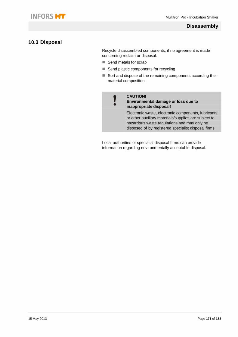
Multitron Pro - Incubation Shaker
Disassembly
15 May 2013 Page 171 of 188
10.3 Disposal Recycle disassembled components, if no agreement is made concerning reclaim or disposal.
Send metals for scrap
Send plastic components for recycling Sort and dispose of the remaining components according their
material composition.
CAUTION! Environmental damage or loss due to inappropriate disposal! Electronic waste, electronic components, lubricants or other auxiliary materials/supplies are subject to hazardous waste regulations and may only be disposed of by registered specialist disposal firms
Local authorities or specialist disposal firms can provide information regarding environmentally acceptable disposal.
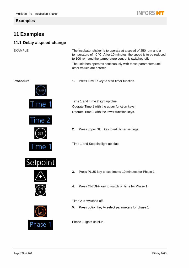
Multitron Pro - Incubation Shaker
Examples
Page 172 of 188 15 May 2013
11 Examples
11.1 Delay a speed change
EXAMPLE The incubator shaker is to operate at a speed of 250 rpm and a temperature of 40 °C. After 10 minutes, the speed is to be reduced to 100 rpm and the temperature control is switched off. The unit then operates continuously with these parameters until other values are entered.
Procedure
1. Press TIMER key to start timer function.
Time 1 and Time 2 light up blue. Operate Time 1 with the upper function keys.
Operate Time 2 with the lower function keys.
2. Press upper SET key to edit timer settings.
Time 1 and Setpoint light up blue.
3. Press PLUS key to set time to 10 minutes for Phase 1.
4. Press ON/OFF key to switch on time for Phase 1.
Time 2 is switched off.
5. Press option key to select parameters for phase 1.
Phase 1 lights up blue.

Multitron Pro - Incubation Shaker
Examples
15 May 2013 Page 173 of 188
6. Press upper PLUS or MINUS key to set parameter Temp to 40 °C.
7. Press ON/OFF key to switch on parameter Temp.
8. Press lower PLUS or MINUS key to set parameter RPM to 250.
9. Press ON/OFF key to switch on parameter RPM.
10. Press option key to select parameters of phase 2.
Phase 2 light up blue.
11. Press PLUS or MINUS key to set parameter RPM to 100.
12. Press ON/OFF key to switch on parameter RPM.
13. Press option key to finish timer settings.
Current active phase blinks blue. The incubation shaker starts with the settings of phase 1. After 10 minutes the speed slows down to 100 RPM and the heating is switched off.

Multitron Pro - Incubation Shaker
Examples
Page 174 of 188 15 May 2013
11.2 Switch-on delay
EXAMPLE The incubator shaker is to start after a delay of 5 minutes and then operate with a speed of 250 rpm and a temperature of 37.5 °C until other values have been entered.
Procedure
1. Press TIMER key.
Time 1 and Time 2 light up blue. Operate Time 1 with the upper function keys.
Operate Time 2 with the lower function keys.
2. Press SET key for timer settings.
Setpoint and Time 1 light up blue.
3. Press PLUS key to set Time 1 to 5 minutes.
4. Press ON/OFF key to switch on Time 1.
Time 2 is switched off.
5. Press option key to select parameters of Phase 1.
Phase 1 lights up blue.
6. Switch off all parameters of Phase 1.

Multitron Pro - Incubation Shaker
Examples
15 May 2013 Page 175 of 188
7. Press option key to select parameters of Phase 2.
Phase 2 lights up blue.
8. Press upper PLUS or MINUS key to set parameter Temp to 37.5 °C.
9. Press ON/OFF key to switch on parameter Temp.
10. Press lower PLUS or MINUS key to set parameter RPM to 250 RPM.
11. Press ON/OFF key to switch on parameter RPM.
12. Press option key to finish timer settings.
Current active phase blinks blue. Incubation shaker starts after 5 minutes with current settings.
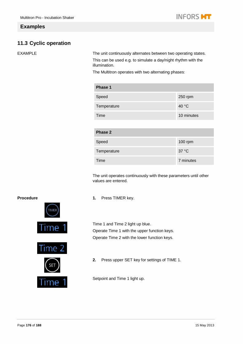
Multitron Pro - Incubation Shaker
Examples
Page 176 of 188 15 May 2013
11.3 Cyclic operation
EXAMPLE The unit continuously alternates between two operating states. This can be used e.g. to simulate a day/night rhythm with the illumination.
The Multitron operates with two alternating phases:
Phase 1
Speed 250 rpm
Temperature 40 °C
Time 10 minutes
Phase 2
Speed 100 rpm
Temperature 37 °C
Time 7 minutes
The unit operates continuously with these parameters until other values are entered.
Procedure
1. Press TIMER key.
Time 1 and Time 2 light up blue. Operate Time 1 with the upper function keys.
Operate Time 2 with the lower function keys.
2. Press upper SET key for settings of TIME 1.
Setpoint and Time 1 light up.
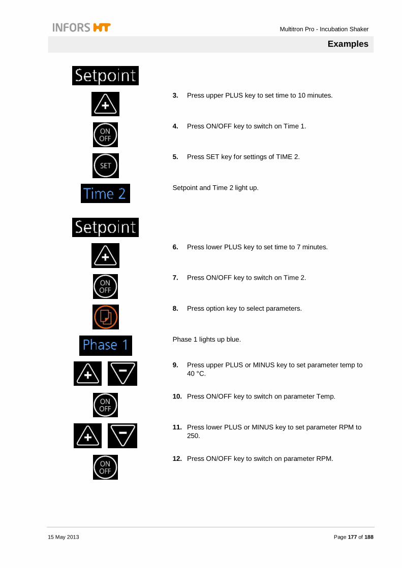
Multitron Pro - Incubation Shaker
Examples
15 May 2013 Page 177 of 188
3. Press upper PLUS key to set time to 10 minutes.
4. Press ON/OFF key to switch on Time 1.
5. Press SET key for settings of TIME 2.
Setpoint and Time 2 light up.
6. Press lower PLUS key to set time to 7 minutes.
7. Press ON/OFF key to switch on Time 2.
8. Press option key to select parameters.
Phase 1 lights up blue.
9. Press upper PLUS or MINUS key to set parameter temp to 40 °C.
10. Press ON/OFF key to switch on parameter Temp.
11. Press lower PLUS or MINUS key to set parameter RPM to 250.
12. Press ON/OFF key to switch on parameter RPM.

Multitron Pro - Incubation Shaker
Examples
Page 178 of 188 15 May 2013
13. Press option key to select Phase 2.
Phase 2 lights up blue.
14. Press upper MINUS key to reduce parameter Temp to 37 °C.
15. Press ON/OFF key to switch on parameter Temp.
16. Press lower MINUS key to reduce parameter RPM to 100.
17. Press ON/OFF key to switch on parameter RPM.
18. Press option key to finish timer settings.
Cycle symbol lights up blue.
Current active phase blinks blue. Incubation shaker starts with settings of phase 1 and alternates with the set cycle.
Multitron Pro - Incubation Shaker
Appendix
15 May 2013 Page 179 of 188
12 Appendix
12.1 Circuit diagram
Fig. 110

Multitron Pro - Incubation Shaker
Appendix
Page 180 of 188 15 May 2013
12.2 Additional information of the use of sterile filters A steam system is sterile by definition. Nevertheless, in case that non-sterile water is used, we recommend integration of a sterile filter as an additional precaution (not included):
PALL AcroPackTM 20 with SUPOR membrane 0,2 µm pore size (0,8 µm pre-filter), sterile
Fig. 111
The filter may be integrated into the water supply tube at any point between the reservoir and the water inlet, preferably close to the water inlet. The bleed valve of the filter must be oriented towards the water reservoir. The transparent plastic bell installed on the filter can be discarded. Operation of the system with sterile filter is identical as described before. The supplier’s specification of 5 L of liquid volume is valid for processing of particle-laden biological liquids. If used for distilled water that is practically particle-free, the life-time of the filter is much higher, depending on the quality of the water. It is not possible, however, to specify the lifetime exactly, please refer to the supplier’s specification for information about integrity testing.
NOTICE!
A new PALL AcroPackTM 20 filter will let air pass easily. Once the filter is wet, air cannot pass anymore. This means that if the reservoir has run empty, the filter will prevent self-priming of the system. In this case, the filter must be removed and placed in a drying oven (max temp. 131 °C for 30 min, lower temperature recommended) until the membrane is dry again or the filter should be replaced by a new filter.
Bleed valve

Multitron Pro - Incubation Shaker
Appendix
15 May 2013 Page 181 of 188
12.3 Purifying Methods
Method Description
Distillation Distilled water is often defined as bottled water that has been produced by a process of distillation. This water is practically free of salts, organic compounds and microorganisms (electrical conductivity of not more than 10 µS/cm and total dissolved solids of less than 10 mg/L). Distillation involves boiling the water and then condensing the steam into a clean container, leaving most solid contaminants behind. Because this process is energy-consuming and ecologically questionable, demineralized water is preferred for most applications.
Deionization / Demineralization Deionized water, also known as demineralized water (DI water, DIW or de-ionized water), is water that has had its mineral ions removed, such as cations from sodium, calcium, iron, copper and anions such as chloride and bromide. Deionization is a physical process which uses specially-manufactured ion exchange resins which bind to and filter out the mineral salts from water.
Because the majority of water impurities are dissolved salts, deionization produces a high purity water that is generally similar to distilled water, and this process is quick and without scale buildup. However, deionization does not significantly remove uncharged organic molecules, viruses or bacteria, except by incidental trapping in the resin. Additionally sterilized demineralized water is often sold as equivalent to distilled water.
Water softening Water softening is the act of reducing the dissolved calcium, magnesium, and to some degree manganese and ferrous iron ion concentration in hard water. A common water softener is sodium carbonate (Na2CO3).

Multitron Pro - Incubation Shaker
Appendix
Page 182 of 188 15 May 2013
Reverse Osmosis Reverse Osmosis is a process that is used to remove a wide range of salts to give water of high purity. Osmosis is a natural process involving fluid flow across a semi-permeable membrane barrier. Reverse osmosis changes the direction of the water flow due to application of pressure on one side of the membrane. The rejection rate of contaminants/salts from the water is generally in the region of 90 to 99.5% depending upon the type of membrane used and water to be treated. This means that a typical mains water supply of around 500 to 700 µS/cm conductivity, when passed through a Reverse Osmosis plant will give water of a conductivity of around 10 µS/cm.
Greater purity can be achieved with a final “polishing” of the water if required.

Multitron Pro - Incubation Shaker
Appendix
15 May 2013 Page 183 of 188
12.4 Roxtec EzEntry 4 Mini
Multitron Pro - Incubation Shaker
Appendix
Page 184 of 188 15 May 2013

Multitron Pro - Incubation Shaker
Index
15 May 2013 Page 185 of 188
13 Index A
Adhesive labels ................................................ 20 Alarm
Acoustic ....................................................... 60 Visual ........................................................... 60
Appendix ....................................................... 179 B
Biohazard ................................................ 17, 144 C
Cleaning
Algae illumination ....................................... 150 Chamber .................................................... 153 CO2 curtain ................................................ 156 Cooling system ........................................... 147 Floor pan .................................................... 153 Glass door pane ......................................... 152 Housing ...................................................... 153 Sticky Stuff adhesive matting ...................... 155 Trays .......................................................... 155
Connection values ........................................... 30
Electrical ...................................................... 30 Conventional use of the equipment .................. 14
Copyright ......................................................... 10 Customer Service ............................................ 10 D
Dimensions Base frame ................................................... 26 Base unit ...................................................... 25 CO2 gassing ................................................. 26 CO2 pressure reducing unit ........................... 26 Cooling units ................................................ 26 Direct steam humidification ........................... 26 Illumination algae ......................................... 27 Illumination daylight / photosynthesis ............ 27 Incubation chamber ...................................... 25 ShakerBag Option gassing ........................... 26
Disassembly
Personnel ................................................... 169
Safety ......................................................... 169 Disposal ......................................................... 171 E
Emissions ....................................................... 51
Environmental protection ................................. 19 Error
Acoustic ...................................................... 60 Visual .......................................................... 60
Examples
Cyclic operation .......................................... 176 Delay a speed change ................................ 172 Switch-on delay .......................................... 174
F
Function
Basic Functions ........................................... 58 Messages .................................................... 59
G
Guarantee ....................................................... 10 I Identification plate ........................................... 52 Initial operation
Personnel .................................................... 87 Safety .......................................................... 87
Installation Connecting the CO2 gas supply.................. 106 Connecting the Direct Steam Humidification 104 Connecting the gassing pipe ....................... 106 External cooling system .............................. 103 Filling with cooling liquid ............................. 101 Installing the incubator shaker ..................... 93 Location requirements ................................. 88 Mounting the drain nozzle ............................ 91 Personnel .................................................... 87 Place of installation ...................................... 88 Removing the transport lock ........................ 90 Safety .......................................................... 87 Setting the adjustable counterweight............ 96 Setting the capillary thermostat .................... 95 Switching on the cooling system ................. 100

Multitron Pro - Incubation Shaker
Index
Page 186 of 188 15 May 2013
Switching on the unit .................................... 92 Installation and initial operation
Minimum distances....................................... 89 Interference
Temperature .............................................. 162 Interferences
Action ......................................................... 157 Broken tube................................................ 167 CO2 gassing .............................................. 162 Error messages .......................................... 160 General ...................................................... 160 Humidity ..................................................... 165 Illumination ................................................. 166 Personnel ................................................... 159 Safety ........................................................ 159 Shaker drive ............................................... 161
L
Liability .............................................................. 9 Load
25 throw ....................................................... 27 50 throw ....................................................... 27
Location requirements for installation ............... 88 M
Maintenance Direct Steam Humidification ....................... 151 Finishing maintenance work ....................... 156 Illumination ................................................. 149 Maintenance plan ....................................... 145 Personnel ................................................... 143 Protective equipment .................................. 143 Replacing the fuse...................................... 147 Safety ........................................................ 143
Moving parts .................................................... 18 O
Operating Starting illumination .................................... 135
Operating conditions ........................................ 50 Operating panel
Displays ....................................................... 68 Keys............................................................. 69 Symbols ....................................................... 66
Operation
Alarm ......................................................... 124 Cooling ....................................................... 134 Direct Steam Humidification........................ 133 Ending a work cycle.................................... 122 General ...................................................... 109 Interrupting operation ................................. 132 Loading the StickyStuff adhesive matting .... 131 Loading tray Sticky Stuff ............................. 131 Operating CO2 gassing ............................... 137 Operating the mobile Pt100 sensor ............. 139 Personnel ................................................... 107 Safety......................................................... 107 Selecting a unit ........................................... 117 Setting the pressure reduction station ......... 139 Setting the timer ......................................... 113 Setting up the pass-through ........................ 140 Starting a work cycle .................................. 119 Starting algae illumination ........................... 137 Stopping shaker table ................................. 123 Switching on the unit .................................. 108 Testing the alarm function .......................... 123 Timer.......................................................... 112 Tray ................................................... 125, 129 Tray inside the chamber ............................. 129 Turn off timer .............................................. 113 Unloading the Sticky Stuff adhesive matting 131 Using the gassing pipe ............................... 139 UV sterilisation ........................................... 133
Operator .......................................................... 12
Options ............................................................ 53 P
Packaging ........................................................ 85 Particular hazards ............................................ 16 Personnel
Disassembly ............................................... 169 Initial operation ............................................. 87 Installation .................................................... 87 Interferences .............................................. 159 Maintenance .............................................. 143 Operation ................................................... 107
Personnel requirements
Qualified electrician ...................................... 13

Multitron Pro - Incubation Shaker
Index
15 May 2013 Page 187 of 188
Qualified personnel....................................... 13 Qualified personnel in biology, biotechnology or
chemical engineering ................................ 13 Protective equipment
Maintenance............................................... 143 Protective cap .............................................. 16 Protective clothes ......................................... 16 Protective gloves .......................................... 16 Safety goggles ............................................. 16 Safety shoes ................................................ 16
R
Repair ............................................................ 168 S
Safety Accidents ..................................................... 19 Disassembly ............................................... 169 Hazardous situations .................................... 19 Initial operation ............................................. 87 Installation .................................................... 87 Interferences .............................................. 159 Maintenance............................................... 143 Operation ................................................... 107 Operator ....................................................... 12 Particular hazards ........................................ 16 Personal protective equipment...................... 16 Personnel Installation and initial operation .... 87 Symbol explanation in safety instructions ....... 8 Transport ...................................................... 84
Setup Adjustable counterweight .............................. 82 Algae Illumination ......................................... 78 Analog interface ........................................... 62 Base unit ...................................................... 53 Bases ........................................................... 63 CO2 gassing ................................................ 73 Cooling systems ........................................... 70 Direct Steam Humidification .......................... 72 Illumination ................................................... 76 Operating panel ............................................ 64 Option Mobile Pt100 sensor .......................... 80 Pass-through ................................................ 79 Reduction Station for CO2 gassing ................ 76 Serial interface ............................................. 61
Sticky Stuff adhesive matting ....................... 72 Transport lock.............................................. 57 UV sterilisation ............................................ 83
Signs .............................................................. 20 Spare parts ..................................................... 10
Specification Adhesive matting Sticky Stuff....................... 42 CO2 curtain .................................................. 48 CO2 gassing ................................................ 47 CO2 pressure reducing unit ......................... 48 Direct steam humidification .......................... 44 External cooling ........................................... 41 Gassing tube ............................................... 48 General information ..................................... 37 Illumination .................................................. 49 Illumination algae......................................... 49 Interface communication protocol ................ 52 Manual mass flow meter .............................. 45 Mobile Pt100-Sensor ................................... 50 Path through ................................................ 44 ShakerBag gassing ..................................... 45 ShakerBag Tray .......................................... 47 Shaking ....................................................... 39 Shaking Variable throw ................................ 39 Side cooling 380 Watt .................................. 40 Temperature ................................................ 37 Top and bottom cooling 1200 W .................. 41 Top and bottom cooling 900 W .................... 41 UV-sterilization of process air ...................... 50
Sterile filters ................................................... 180 Sticky Stuff
Loading adhesive matting ........................... 131 Replacing the adhesive matting .................. 151 Setup .......................................................... 72 Unloading matting....................................... 131
Storage
Incubator shaker .......................................... 86 Symbols .......................................................... 20
Biohazards .................................................. 20 Hot surfaces ................................................ 20 in danger zone............................................. 20
T
Throw 50 mm speeds ...................................... 40

Multitron Pro - Incubation Shaker
Index
Page 188 of 188 15 May 2013
Timer Multiple changeover ................................... 115 Remaining runtime ..................................... 116 Single changeover...................................... 114
Transport
Fork lift ......................................................... 86 Inspection .................................................... 84 Safety .......................................................... 84
Trouble shooting ............................................ 159 U
Unauthorised persons ...................................... 14 Utilities ............................................................. 51
W
Weights ........................................................... 27 Base frame ................................................... 28 Base unit ...................................................... 27 Cooling units ................................................ 29 Direct steam humidification ........................... 29 Gasing ShakerBag Option ............................ 29 Gassing unit CO2 ......................................... 29 Illumination ................................................... 29 M-tray........................................................... 28 Perforated tray ............................................. 28 ShakerBag Tray ........................................... 29


