1 | Page INDEX Name of work: - Data Centre Air conditioning Works of new HPC (High Performance Computing) facility under NSM (National Supercomputing Mission), at Computer Centre in IIT Kanpur. NIT amounting to Rs.1,13,48,331/- is approved. Executive Engineer Superintending Engineer I.W.D. Elect. & AC Divn. Central Office, I.W.D. I.I.T., Kanpur I.I.T., Kanpur S. No. Description Page Index Page 1 PART-A 2 1 E-Tender Notice 3 2. Information and e-Tendering for Contractors 4-5 3. Notice Inviting Tenders (Form CPWD–6) 6-10 4. Tender (Form CPWD–7) 11-17 5. Salient/Mandatory requirement for tender 18 6. PART-B 19 7. Quality Assurance of the work 20 8. Additional terms & conditions 21-23 9. General Conditions 24 10. Special conditions 25-32 11 Appendix B 33 12 Content 34 13 Special conditions of contract-Technical 35-54 14 Equipment Specifications 55-76 15 List of approved make 77-78 16 Technical Data Sheet 79-86 17 Schedule of quantities 87-88 18 Annexure A 89
Transcript
1 | P a g e
INDEX Name of work: - Data Centre Air conditioning Works of new HPC (High Performance Computing) facility under NSM (National Supercomputing Mission), at Computer Centre in IIT Kanpur.
NIT amounting to Rs.1,13,48,331/- is approved.
Executive Engineer Superintending Engineer I.W.D. Elect. & AC Divn. Central Office, I.W.D.
I.I.T., Kanpur I.I.T., Kanpur
S. No. Description
Page
Index Page 1
PART-A 2
1 E-Tender Notice 3
2. Information and e-Tendering for Contractors 4-5
3. Notice Inviting Tenders (Form CPWD–6) 6-10
4. Tender (Form CPWD–7) 11-17
5. Salient/Mandatory requirement for tender 18
6. PART-B 19
7. Quality Assurance of the work 20
8. Additional terms & conditions 21-23
9. General Conditions 24
10. Special conditions 25-32
11 Appendix B 33
12 Content 34
13 Special conditions of contract-Technical 35-54
14 Equipment Specifications 55-76
15 List of approved make 77-78
16 Technical Data Sheet 79-86
17 Schedule of quantities 87-88
18 Annexure A 89
2 | P a g e
3 | P a g e
INDIAN INSTITUTE OF TECHNOLOGY KANPUR INSTITUTE WORKS DEPARTMENT
NIT No. 20/AC/2018/ 573 Dated : 20.09.2018 The Superintending Engineer, IWD, I.I.T., Kanpur on behalf of Board of Governors of IIT Kanpur invites online item rate tender from eligible air conditioning contractors/specialized agencies for the following Data Centre air-conditioning work:-
Sl. No
Name of work and location
Estimated cost put to
tender (In Rs.)
Earnest Money (In Rs.)
Period of
Completion (in
Month)
Last date & time of
submission of tender
Period during which EMD, Cost of Tender Document, e-Tender Processing Fee and other Documents shall be submitted
Time & date of opening of tender
1 Data Centre Air conditioning Works of new HPC (High Performance Computing) facility under NSM( National Supercomputing Mission), at Computer Centre in IIT Kanpur.
Rs. 1,13,48,331/-
Rs. 2,26,967/
-
04 Months
Upto 3.30 PM on
15.10.2018
After last date and time of sub-mission of tender and upto 3:30 PM on 17.10.2018
At 3:30 PM on
22.10.2018
The E-tender documents is available on www.tenderwizard.com/IIT
(Rajeev Garg)
Superintending Engineer Copy to:
1. Institute website: www.iitk.ac.in/iwd/tenderhall.htm 2. Notice Board
1. The intending tenderer must read the terms and conditions of FORM-6 for e-Tendering carefully. He should only submit his tender if he considers himself eligible and he is in possession of all the documents required.
2. Information and Instructions for tenderer posted on website shall form part of tender document.
3. The tender document consisting of plans, specifications, the schedule of quantities of various types of items to be executed and the set of terms and conditions of the contract to be complied with and other necessary documents can be seen and downloaded from website www.tenderwizard.com/IIT or www.iitk.ac.in free of cost.
4. But the tender can only be submitted after uploading the mandatory scanned documents as per list given below.
5. The intending tenderer has to fill all the details such as Banker's name, Demand Draft/Fixed Deposit Receipt /Pay Order/ Banker's Cheque/Bank Guarantee number, amount and date.
The amount of EMD can be paid by multiple Demand Draft / Pay Order / Banker's
Cheque / Deposit at call receipt / Fixed Deposit Receipts along with multiple Bank
Guarantee of any Scheduled Bank if EMD is also acceptable in the form of Bank
Guarantee.
6. Those contractors not registered on the website mentioned above, are required to get registered beforehand. If needed they can be imparted training on online bidding process as per details available on the website.
7. The intending tenderer must have valid class-III digital signature to submit the tender.
8. On opening date, the contractor can login and see the tender opening process. After opening of tenders he will receive the competitor tender sheets.
9. Contractor can upload documents in the form of JPG format and PDF format.
10. Contractor must ensure to quote rate of each item. The column meant for quoting
rate in figures appears in pink colour and the moment rate is entered, it turns sky
blue.
11. In addition to this, while selecting any of the cells a warning appears that if any cell is
left blank the same shall be treated as “0”.
12. Therefore, if any cell is left blank and no rate is quoted by the tenderer, rate of such
item shall be treated as “0” (ZERO).
5 | P a g e
13. List of Documents to be scanned and uploaded within the period of tender
submission:
Copy of Registration with the Department if any or specialized agencies.
Required experience / completion certificates of similar nature of works. The works certificates submitted by the bidder clearly indicate that:
1. The completion certificate cost of the Data Centre air-conditioning works
2. Actual date of completion of the air-conditioning work.
Copy of EPF & ESI No.
Details of turn over during the last three years.
Copy of bank solvency certificate
E.M.D.
Copy of GST Registration
6 | P a g e
FORM -6 FOR e-Tendering
The Superintending Engineer, IWD, I.I.T., Kanpur on behalf of Board of Governors of IIT Kanpur invites online item rate tenders for the following works from eligible Air conditioning contractors/specialised agencies: “Data Centre Air conditioning Works of new HPC (High Performance Computing) facility under NSM (National Supercomputing Mission), at Computer Centre in IIT Kanpur.”
The work is estimated to cost Rs. 1,13,48,331/- This estimate, however, is given merely as a rough guide.
1.1 The authority competent to approve NIT for the combined cost and belonging to the major discipline will consolidate NITs for calling the tenders. He will also nominate Division which will deal with all matters relating to the invitation of tenders.
2. Criteria of eligibility
1. Copy of Registration with the Department if any or specialized agencies of Data Centre air-conditioning works.
2. The Tenderer should have completed satisfactorily at least *3 similar works each of value 40% of the estimated cost or *2 similar works of 50% of the estimated cost or *1 similar work of 80% of estimated cost during the last 7(seven) years. (at least one work of them should be in Central Govt. /Central Autonomous bodies/ Central PSU/State PSU /State Govt.).
3. Similar nature of work means: Works of Data Centre air-conditioning with chilled water system, cooling distribution units for direct server rack cooling, SITC of raised floor tiles & PAC (precision air conditioning) works.
4. The details of average annual financial turnover on air-conditioning works should be at least 100% of the estimated cost during the last 3 consecutive financial years, list of works completed of the requisite magnitude along with the attested copies of certificates of satisfactory completion”.
5. Having ESI & EPF registration No. of government authorities.
6. Having a bank solvency certificate not less of 40% of estimated cost.
7. Having GST registration.
3. Agreement shall be drawn with the successful tenderers on prescribed Form No.
CPWD 7 (or other Standard Form as mentioned) which is available as a Govt. of India Publication and also available on website www.iitk.ac.in Tenderers shall quote his rates as per various terms and conditions of the said form which will form part of the agreement.
4. The time allowed for carrying out the work will be 4 Months from the date of start
as defined in schedule „F‟ or from the first date of handing over of the site, whichever is later, in accordance with the phasing, if any, indicated in the tender documents.
5. The site for the work is available.*
7 | P a g e
5.1 The tender proceedings shall be held as per the following schedule: i) Last date of tender submission : 15.10.2018 upto 3:30 PM
ii) Date of pre-bid meeting : 08.10.2018 at 3:30 PM in the office of Undersigned
iii) Last date of document receipt : 17.10.2018 upto 3:30 PM of tender
iv) Date of opening tender : 22.10.2018 at 3:30 PM
6. The tender document consisting of plans, specifications, the schedule of
quantities of various types of items to be executed and the set of terms and conditions of the contract to be complied with and other necessary documents except Standard General Conditions of Contract Form can be seen on website www.tenderwizard.com/IIT, https://eprocure.gov.in/cppp/latestactivetenders or www.iitk.ac.in other necessary documents also can be seen in the office of the EE , IWD Electrical and Air conditioning Division, IIT, Kanpur between hours of 10:00 AM to 5:30 PM from 28.09.2018 to 15.10.2018 free of cost.
7. After submission of the tender the contractor can re-submit revised tender any
number of times but before last time and date of submission of tender as notified. 8. While submitting the revised tender, contractor can revise the rate of one or more
item(s) any number of times (he need not re-enter rate of all the items) but before last time and date of submission of tender as notified.
9. When tenders are invited in three stage system and if it is desired to submit
revised financial tender then it shall be mandatory to submit revised financial tender. If not submitted then the tender submitted earlier shall become invalid.
10. Earnest Money can be paid in the form of Treasury Challan or Demand Draft or
Pay order or Banker`s Cheque or Deposit at Call Receipt or Fixed Deposit Receipt (drawn in favour of Director, IIT, Kanpur along with Bank Guarantee of any Scheduled Bank wherever applicable.
A part of earnest money is acceptable in the form of bank guarantee also. In such case, 50% of earnest money or Rs. 20 lac, whichever is less, will have to be deposited in shape prescribed above, and balance in shape of Bank Guarantee of any scheduled bank. (i) Cost of Tender Document – Rs. 1180/- (Including GST) drawn in favour
of the Director IIT, Kanpur through e-payment (ii) e-Tender Processing Fee – Rs. 8850/- (including GST) drawn in favour of
"ITI Limited" payable at Delhi through e-payment Treasury Challan or Demand Draft or Pay Order or Banker`s Cheque or Deposit
at Call Receipt or FDR or Bank Guarantee against EMD, Cost of Tender Document and Cost of Tender Processing Fee shall be placed in single sealed envelope superscripted as “Earnest Money, Cost of Tender Document and Cost of Tender Processing Fee” with name of work and due date of opening of the tender also mentioned thereon.
Copy of Enlistment Order and certificate of work experience wherever applicable and other documents if required and specified in this bid document shall be scanned and uploaded to the e-Tendering website within the period of tender submission and certified copy of each shall be deposited in a separate envelop marked as “Other Documents”.
Both the envelopes shall be placed in another envelope with due mention of Name of work, date & time of opening of tenders and to be submitted in the office of Superintending Engineer after last date & time of submission of tender and up to 03:30 PM on 17.10.2018. The documents submitted shall be opened at 4.00 PM on 17.10.2018.
Online tender documents submitted by intending tenderers shall be opened only of those tenderers, whose Earnest Money Deposit, Cost of Tender Document and e-Tender Processing Fee and other documents placed in the envelope are found in order.
The tender submitted shall be opened at 03:30 PM on 22.10.2018. 11. The tender submitted shall become invalid and cost of tender & e-Tender
processing fee shall not be refunded if: (i) The tenderers is found ineligible. (ii) The tenderers does not upload all the documents as stipulated in the tender
document. (iii) If any discrepancy is noticed between the documents as uploaded at the
time of submission of tender and hard copies as submitted physically in the office of tender opening authority.
12. The contractor whose tender is accepted will be required to furnish performance guarantee of 5% (Five Percent) of the tendered amount within the period specified in Schedule F. This guarantee shall be in the form of cash (in case guarantee amount is less than ` 10000/-) or Deposit at Call receipt of any scheduled bank/Banker‟s cheque of any scheduled bank/Demand Draft of any scheduled bank/Pay order of any Scheduled Bank of any scheduled bank (in case guarantee amount is less than ` 1,00,000/-) or Government Securities or Fixed Deposit Receipts or Guarantee Bonds of any Scheduled Bank or the State Bank of India in accordance with the prescribed form. In case the contractor fails to deposit the said performance guarantee within the period as indicated in Schedule „F‟, including the extended period if any, the Earnest Money deposited by the contractor shall be forfeited automatically without any notice to the contractor.
13. Intending Tenderers are advised to inspect and examine the site and its
surroundings and satisfy themselves before submitting their tenders as to the nature of the ground and sub-soil (so far as is practicable), the form and nature of the site, the means of access to the site, the accommodation they may require and in general shall themselves obtain all necessary information as to risks, contingencies and other circumstances which may influence or affect their tender. A tenderers shall be deemed to have full knowledge of the site whether he inspects it or not and no extra charge consequent on any misunderstanding or otherwise shall be allowed. The tenderers shall be responsible for arranging and maintaining at his own cost all materials, tools, & plants, water, electricity access, facilities for workers, and all other services required for executing the work unless otherwise specifically provided for in the contract documents. Submission of a tender by a tenderer implies that he has read this notice and all other contract documents and has made himself aware of the scope and specifications of the
9 | P a g e
work and local conditions and other factors having a bearing on the execution of the work.
14. The competent authority on behalf of the Board of Governors, IIT, Kanpur does
not bind itself to accept the lowest or any other tender and reserves to itself the authority to reject any or all the tenders received without the assignment of any reason. All tenders in which any of the prescribed condition is not fulfilled or any condition including that of conditional rebate is put forth by the tenderers shall be summarily rejected.
15. Canvassing whether directly or indirectly, in connection with tenderers is strictly
prohibited and the tenders submitted by the contractors who resort to canvassing will be liable for rejection.
16. The competent authority on behalf of Board of Governors, IIT, Kanpur reserves
to himself the right of accepting the whole or any part of the tender and the tenderers shall be bound to perform the same at the rate quoted.
17. The contractor shall not be permitted to tender for works in the IIT Kanpur
responsible for award and execution of contracts, in which his near relative is posted a Divisional Accountant or as an officer in any capacity between the grades of Superintending Engineer and Junior Engineer (both inclusive). He shall also intimate the names of persons who are working with him in any capacity or are subsequently employed by him and who are near relatives to any gazetted officer in the IIT Kanpur. Any breach of this condition by the contractor would render him liable to be removed from the approved list of contractors of this Department.
18. No Engineer of Gazetted Rank or other Gazetted Officer employed in
Engineering or Administrative duties in an Engineering Department of the Government of India is allowed to work as a contractor for a period of one year after his retirement from Government service, without the prior permission of the Government of India in writing. This contract is liable to be cancelled if either the contractor or any of his employees is found any time to be such a person who had not obtained the permission of the Government of India as aforesaid before submission of the tender or engagement in the contractor‟s service.
19. The tender for the works shall remain open for acceptance for a period of ninety
(90) days from the date of opening of tenders if any tenderer withdraws his tender before the said period or issue of letter of acceptance, whichever is earlier, or makes any modifications in the terms and conditions of the tender which are not acceptable to the department, then the Government shall, without prejudice to any other right or remedy, be at liberty to forfeit 50% of the said earnest money as aforesaid. Further the tenderers shall not be allowed to participate in the retendering process of the work.
20. This Notice Inviting Tender shall form a part of the contract document. The
successful tenderers/contractor, on acceptance of his tender by the Accepting Authority shall within 15 days from the stipulated date of start of the work, sign the contract consisting of:-
10 | P a g e
a) The Notice Inviting Tender, all the documents including additional
conditions, specifications and drawings(indicative only), if any, forming part of the tender as uploaded at the time of invitation of tender and the rates quoted online at the time of submission of tender and acceptance thereof together with any correspondence leading thereto.
b) Standard C.P.W.D. Form 7 or other Standard C.P.W.D. Form as applicable.
20.1.1 The tender document will include following three components:
Part A:-
CPWD-6, CPWD-7 including schedule A to F for the major component of the work, Standard General Conditions of Contract for CPWD 2014 as amended/modified up to 15.10.2018.
Part B:- General/specific conditions, specifications and schedule of quantities applicable to major component of the work.
Part C:- Schedule A to F for minor component of the work. (SE/EE in charge of major component shall also be competent authority under clause 2 and clause 5 as mentioned in schedule A to F for major components), General/specific conditions, specifications and schedule of quantities applicable to minor component(s) of the work.
20.1.2 The tenderers must associate himself, with agencies of the appropriate class eligible to tender for each of the minor component individually.
20.1.3 The eligible tenderers shall quote rates for all items of major component as well
as for all items of minor components of work. 20.1.4 Entire work under the scope of composite tender including major and all minor
components shall be executed under one agreement. 20.1.5 Security Deposit will be worked out separately for each component
corresponding to the estimated cost of the respective component of works. The Earnest Money will become part of the security deposit of the major components of work.
21. The EPF & ESI contribution paid to the contract workers shall be reimbursed on
actual basis.
Superintending Engineer
For & on behalf of the Board of Governors, IIT, Kanpur
11 | P a g e
CPWD-7 ITEM RATE TENDER AND CONTRACT FOR WORK
(A) Tender for the work of : Data Centre Air conditioning Works of new HPC
(High Performance Computing) facility under NSM
(National Supercomputing Mission), at Computer
Centre in IIT Kanpur.
TENDER
I/We have read and examined the Notice Inviting tender, schedule, A,B,C,D,E&F. Specifications applicable, Drawings & Designs, General Rules and Directions, Conditions of Contract, clauses of contract, Special conditions, Schedule of Rate & other documents and rules referred to in the conditions of contract and all other contents in the tender document for the work.
I/We hereby tender for the execution of the work specified for the Board of Governors, IIT, Kanpur within the time specified in Schedule „F‟, viz., schedule of quantities and in accordance in all respects with the specifications, designs, drawings and instructions in writing referred to in Rule-1 of General Rules and Directions and in Clause 11 of the Conditions of contract and with such materials as are provided for, by, and in respects in accordance with, such conditions so far as applicable.
We agree to keep the tender open for (90) ninety days from the date of opening of tender and not to make any modifications in its terms and conditions.
A sum of Rs. 2,26,967/- is hereby forwarded in Cash/Receipt Treasury Challan/Deposit at call Receipt of a Scheduled Bank/Fixed deposit receipt of scheduled bank/demand draft of a scheduled bank/bank guarantee issued by scheduled bank as earnest money. If I/we, fail to furnish the prescribed performance guarantee or fail to commence the work within prescribed period I/we agree that the said Board of Governors, IIT, Kanpur or his successors in office shall without prejudice to any other right or remedy be at liberty to forfeit the said earnest money absolutely. Further, if I/we fail of commence work as specified, I/we agree that Board of Governors, IIT, Kanpur or his successors in office shall without prejudice to any other right or remedy available in law, be at liberty to forfeit the said earnest money and the performance guarantee absolutely, otherwise the said earnest money shall be retained by him towards security deposit to execute all the works referred to in the tender documents upon the terms and conditions contained or referred to therein and to carry out such deviations as may be ordered, up to maximum of the percentage mentioned in Schedule „F‟ and those in excess of that limit at the rates to be determined in accordance with the provision contained in Clause 12.2 and 12.3 of the tender form.
Further, I/We agree that in case of forfeiture of earnest money or both Earnest Money & Performance Guarantee as aforesaid, I/We shall be debarred for participation in the re-tendering process of the work.
12 | P a g e
I/We undertake and confirm that eligible similar work(s) has/ have not been got executed through another contractor on back to back basis. Further that, if such a violation comes to the notice of Department, then I/we shall be debarred for tendering in IIT, Kanpur in future forever. Also, if such a violation comes to the notice of Department before date of start of work, the Engineer-in-Charge shall be free to forfeit the entire amount of Earnest Money Deposit/Performance Guarantee.
I/We hereby declare that I/we shall treat the tender documents drawings and other records connected with the work as secret/confidential documents and shall not communicate information derived there from to any person other than a person to whom I/we am/are authorized to communicate the same or use the information in any manner prejudicial to the safety of the State.
** Dated ______**_________ Signature of contractor Postal Address ** Witness: ** Address: ** Occupation: **
13 | P a g e
The above tender (as modified by you as provided in the letters mentioned hereunder) is
accepted by me for and on behalf of the Board of Governors, IIT, Kanpur for a sum of
Operative schedules shall be supplied separately to each intending tenderer
SCHEDULE „A‟ Schedule of Quantities:
SCHEDULE „B‟
Schedule of materials to be issued to the contractor:
S. No.
Description of item Quantity Rates in figures & words at which the material will be charged to the contractor
Place of issue
1 2 3 4 5
--------------NIL ----------------
SCHEDULE „C‟ Schedule of Tools and Plants to be hired to the contractor
S. No.
Description Hire charges per day
Place of issue
1 2 3 4
--------------NIL ----------------
SCHEDULE „D‟ Extra schedule for specific requirements/document for the work, if any: As attached in tender form.
SCHEDULE „E‟ Schedule of component of other Materials, Labour, POL etc. for price escalation: N.A.
SCHEDULE „F‟ Reference to General Conditions of contract.
Name of Work: Data Centre Air conditioning Works of new HPC (High Performance Computing) facility under NSM (National Supercomputing Mission), at Computer Centre in IIT Kanpur.
Estimated cost of the work: Air-conditioning Items of Work
1,13,48,331/-
15 | P a g e
Earnest money 2,26,967/-
Performance Guarantee 5% of the tendered value of the work
Security Deposit 5% of the tendered value of the work
General rules and direction :
Definitions: 2(v) Engineer-in-Charge
For Air-conditioning & Refrigeration/Electrical items of work
Executive Engineer, Institute Works Department IIT, Kanpur
2(vi) Accepting Authority Superintending Engineer, Institute Works Department IIT, Kanpur
2(vii) Percentage on cost of materials and labour to cover all overheads and profits
15%
2(viii) Standard Schedule of Rates:
Electrical Items of Work: D.S.R. 2018 with up to date correction slips
2(ix) Department: Central Public Works Department
2(x) Standard CPWD contract Form: GCC 2014, CPWD form-7 as modified & corrected up to 15.10.2018 (Whether correction vide latest circulars are incorporated or not in this document).
Clause 1 i) Time allowed for submission of Performance Guarantee from the date of issue of letter of acceptance
ii) Maximum allowable extension beyond the period as provided in i) above
15 Days
7 Days
Clause 2 Authority for fixing Compensation under Clause 2
Superintending Engineer, Institute Works Department IIT, Kanpur. Or successor thereof
Clause 2 A Whether Clause 2A shall be applicable
No
Clause 5 i) Number of days from the date of issue of letter of acceptance for reckoning date of start
22 Days
ii) Time allowed for execution of
work 4 Months
Authority to decide
Extension of time Superintending Engineer, Institute Works Department IIT, Kanpur
16 | P a g e
Clause 6/ 6A
Only clause 6 applicable.
Clause 7 Gross work to be done together with net payment/Adjustment of advances for material collected, if any, since the last such payment for being eligible to interim payment
Not applicable
Clause 10A Material to be provided by the contractor. Applicable
Clause 10B (ii), (iii)
Whether clause 10-B (ii) and 10-B (iii) shall be applicable. Not Applicable
Clause 10 C Component of labour expressed as percentage of value of work
---
Clause 10 CA
Materials covered under this clause.
Nearest material(other than
cement, reinforcement bars
and structural steel) for which
All India Whole sale price
Index is to be followed.
Base price of all
the materials
covered under
clause 10 CA
1. Cement (PPC) 2. Steel
Nil Nil
NIL Nil
Clause 10 CC
Increase/Decrease in Price of materials/wages
Not Applicable
Clause 11 Specification to be followed for execution of work:
For electrical works
CPWD specifications 2013 internal and 2013 external electrical works
For Air conditioning & Refrigeration item of works
CPWD Specifications 2017 HVAC for Air-conditioning & refrigeration works with up to date correction slips.(Hereinafter called CPWD specifications also)
Clause 12
12.2 & 12.3 Deviation limit beyond which clause 12.2 & 12.3 shall apply for building
work
---
17 | P a g e
Clause 16 Competent Authority for Deciding reduced rates:
For electrical/civil/Air-conditioning& refrigeration items of work
Superintending Engineer, Institute Works Department IIT, Kanpur
Clause 18 List of mandatory machinery, tools & plants to be deployed by the contractor at site.
Ladders, Multimeter, drill machine, crimping tools, spanner set, blower, Gas Charging line with equipment, welding torch etc
Clause 36 (i) Requirement of technical Representative(s)
For supervision of air-conditioning/refrigeration & civil as well as electrical items of work, technical representatives of the respective disciplines will be required to be deployed.
Sl.No.
Minimum Qualification of Technical Representative D
Rate at which recovery shall be made from the contractor in the event of not fulfilling provision of clause 36(i)
Figures Words
1. B.E/B-Tech Electrical / mechanical
Graduate Engineer
5 1 Rs.21,000/- p.m
Fifteen Thousand per month
2. Diploma Electrical / mechanical
Diploma Engineer
5 1 Rs.15,000/- p.m
Ten Thousand per month
Assistant Engineers retired from Government services that are holding Diploma will be treated at par with Graduate Engineers. Clause 42 : i) a) Schedule statement for determining theoretical : DSR – 2018 Printed by CPWD Quantities of cement & bitumen on the basis of. ii) Variations permissible on theoretical quantities
a) Cement for works with estimated cost put to tender not more than Rs.5 lakhs : Not applicable
For works with estimated cost put to tender
more than Rs.5 lakhs : Not applicable b) Bitumen for all works : Not applicable c) Steel Reinforcement and structural steel sections for each diameter, section and category : Not applicable d) All other materials : Nil
18 | P a g e
Name of Work:
Data Centre Air conditioning Works of new HPC (High Performance Computing) facility under NSM (National Supercomputing Mission), at Computer Centre in IIT Kanpur.
1 The tenderer is advised to read and examine the tender documents for the work and the set of indicative drawings available with Engineer-in-charge. He should inspect and examine the site and its surroundings by himself before submitting his tender.
2 Separate schedule of quantity is included in this tender for air conditioning & refrigeration items of work. If the tenderer wants to offer any unconditional rebates on their rates, the same should also be offered in the respective components of schedule separately. The contractor shall quote the item rates in figures and words accurately so that there is no discrepancy in rates written in figures and words.
3 Time allowed for the execution of work is 04 Months.
4 The contractor(s) shall submit a detailed program of execution in accordance with the master programme/milestone within ten days from the date of issue of award letter.
5 Contractor has to arrange and install field laboratory during the currency of work and nothing extra will be paid on this account.
6 Quality of the project is of utmost importance. This shall be adhered to in accordance with the provisions of CPWD specifications and guidelines given in the relevant paras.
7 Contractor has to deploy required Plant and machinery on the project. In case the contractor fails to deploy the plant and machinery whenever required and as per the direction of the Engineer-in-charge, he (Engineer-in-charge) shall be at a liberty to get the same deployed at the risk and cost of the contractor.
8 The contractor shall comply with the provisions of the Apprentices Act 1961, and the rules and orders issued there under from time to time. If he fails to do so, his failure will be a breach of the contract and the Superintending Engineer/Executive Engineer may in his discretion, without prejudice to any other right or remedy available in law, cancel the contract. The contractor shall also be liable for any pecuniary liability arising on account of any violation by him of the provisions of the said Act.
9 Temporary Electric connection shall be issued as per request and the water charges shall be recovered as per rule.
19 | P a g e
20 | P a g e
QUALITY ASSURANCE OF THE WORK Sampling of Materials:
1. The contractor shall procure all the materials at least in advance so that there is sufficient time to testing and approving of the materials and clearance of the same before use in work.
2. All materials brought by the contractor for use in the work shall be got checked from the Engineer-in-Charge or his authorized representative of the work on receipt of the same at site before use.
3. The contractor shall be fully responsible for the safe custody of the materials issued to him even if the materials are in double lock and key system.
21 | P a g e
1 Unless otherwise provided in the Schedule of Quantities/Specifications, the rates tendered by the contractor shall be all inclusive and shall apply to all heights, lifts, leads and depths of the work and nothing extra shall be payable to him on account of the same. Extra payment for centering/shuttering, if required to be done for heights greater than 3.5 m shall however be admissible at the rates arrived at in accordance with clause 12 of the agreement, if not already specified.
2 Other agencies doing works related with this project may also simultaneously execute their works and the contractor shall afford necessary facilities for the same. The contractor shall leave such necessary holes, openings etc. for laying/burying in the work, pipes cables, conduits, clamps, boxes and hooks for fan clamps etc. as may be required for the other agencies. Nothing extra over the Agreement rates shall be paid for doing these.
3 Some restrictions may be imposed by the security staff etc. on the working and for
movement of labour, materials etc. The contractor shall be bound to follow all such restrictions/instructions and nothing extra shall be payable on account of the same.
4.1 The contractor shall fully comply with all legal orders and directions of the Public
or local authorities or municipality and abide by their rules and regulations and pay all fees and charges for which he may be liable in this regard. Nothing extra shall be paid/reimbursed for the same.
4.2 The building work shall be carried out in the manner complying in all respects with the requirements of the relevant bylaws and regulations of the local body under the jurisdiction of which the work is to be executed or as directed by the Engineer-in-charge and nothing extra shall be paid on this account.
5 If as per local Municipal regulations, huts for labour are not to be erected at the
site of work; the contractor shall be required to provide such accommodation at a place as is acceptable to the local body and nothing extra shall be paid on this account.
6 The structural and architectural drawings shall at all times be properly co-related before executing any work. However, in case of any discrepancy in the item given in the schedule of quantities appended with the tender and Architectural drawings relating to the relevant item, the former shall prevail unless otherwise given in writing by the Engineer-in-charge.
7.1 For the purpose of recording measurements and preparing running account bills,
the abbreviated nomenclature indicated in the publications Abbreviated Nomenclature of Items of DSR 2012 shall be accepted. The abbreviated nomenclature shall be taken to cover all the materials and operations as per the complete nomenclature of the relevant items in the agreement and relevant specifications.
22 | P a g e
7.2 In case of items for which abbreviated nomenclature is not available in the
aforesaid publication and also in case of extra and substituted items for which abbreviated nomenclature are not provided for in the agreement, full nomenclature of item shall be reproduced in the measurement books and bill forms for running account bills.
7.3 For the final bill, however, full nomenclature of all the items shall be adopted in
preparing abstract in the measurement books and in the bill forms.
8. The contractor shall take instructions from the Engineer-in-charge for stacking of materials. No excavated earth or building materials etc. shall be stacked/collected in areas where other buildings, roads, services, compound walls etc. are to be constructed.
9 Any trenching and digging for laying sewer lines/water lines/cables etc. shall be
commenced by the contractor only when all men, machinery‟s and materials have been arranged and closing of the trench(s) thereafter shall be ensured within the least possible time.
10 It shall be ensured by the contractor that no electric live wire is left exposed or unattended to avoid any accidents in this regard.
11 In case the supply of timber/steel frames/shutters for doors, windows etc. is made
by some other agency, the contractor shall make necessary arrangements for their safe custody on the direction of the Engineer-in-charge till the same are fixed in position by him & nothing extra shall be paid on this account.
12 The contractor shall maintain in perfect condition, all portions executed till
completion of the entire work allotted to him. Where however phased delivery of work is contemplated these provisions shall apply separately to each phase.
13 The entire royalty at the prevalent rates shall have to be paid by the contractor on
all the boulders, metals, shingle sand etc. collected by him for execution of the work, directly to the Revenue authority or authorized agents of the State Government concerned or the Central Government, as the case may be.
14.1 The contractor shall bear all incidental charges for cartage, storage and safe
custody of materials issued by the departments and shall construct suitable go downs, yards at the site of work for storing all materials as to be safe against damage by sun, rain, dampness, fire, theft etc. at his own cost and also employ necessary watch and ward establishment for the purpose, at his own cost. Materials to be charged directly to work and stipulated for issue free of cost shall also be issued to the contractor as soon as those are received at site or at the stipulated place of issue. The provision of this para shall apply equally and fully to those as well.
14.2 All materials obtained from the Institute Works Department store or otherwise on receipt shall be got checked by the Engineer-in-charge of the work or his representations before use.
23 | P a g e
14.3 Registers for the materials to be issued by the department shall be maintained as
required by the Engineer-in-charge and these shall be signed by the contractor or his authorized agent and representative of Engineer-in-charge on each day of transactions.
24 | P a g e
GENERAL CONDITIONS
Tenders have been invited on the basis of Standards Forms 7/8 and General Conditions of Contract for works in Central Public Works Department (CPWD). However in the contract of IIT Kanpur, the following terms may be read as:
Sl. No.
As per Standard Forms To be Read as
1. President of India Board of Governors, IIT Kanpur.
2. Government of India Indian Institute of Technology Kanpur
3. Central Public Works Department Institute Works Department
4. Chief Engineer Deputy Director
5. Circle Central Office
Superintending Engineer & Head Institute Works Department
25 | P a g e
SPECIAL CONDITIONS
1. In the Contract (as hereinafter defined) the following definitions words and expressions
shall have the meaning hereby assigned to them except where the context otherwise required.
i) Institute shall mean the Indian Institute of Technology (IIT), Kanpur ii) The President shall mean the Board of Governor, IIT Kanpur.
iii) The Engineer In-charge shall mean the Executive Engineer for electrical and Air-
conditioning works.
iv) Government or Govt. of India shall mean the Indian Institute of Technology represented by its Director.
v) The term Director General of Works shall mean the Chairman, Building & Works
Committee of the Institute.
vi) Accepting authority shall mean the Director, IIT Kanpur or his authorized representative.
vii) Superintending Engineer shall mean the Superintending Engineer of the Institute,
who as overall In-charge and head of the Institute Works Department shall direct the contract.
viii) Site Engineers shall mean the Assistant Engineer for Electrical & Air-conditioning
works, appointed by the Institute Works Department.
ix) The user/owner shall mean the Head, Computer Centre and Engineers of the Computer centre, under whose control and guidance work will be executed.
2. Duties & Powers :
i) Site Engineers:
The duties of the Site Engineer(s) are to watch and supervise the works and the workmanship employed in connection with the works, and to test and examine any materials to be used. He shall have no authority to relieve the contractor of any of his duties or obligations under the contract nor, except as expressly provided here under, to order any work involving delay or any extra payment by the Institute, nor to make any variation in the works. The Engineer-in-charge, from time to time in writing, delegate to the Site Engineer (s) any of the powers and authorities vested in them. Any written instruction or written approval given by the Site Engineer (s) to the contractor within the terms of such delegation (but not otherwise) shall bind the contractor and the Institute as though it had been given by the Engineer-in-charge provided always as follows :
26 | P a g e
a) Failure of the Site Engineer (s) to disapprove any work or materials shall not
prejudice the power of the Engineer In-charge to subsequently disapprove such work or materials and to order the pulling down, removal or breaking up thereof.
b) If the contractor is dissatisfied by reason of any decision of the Site Engineer
(s), he shall be entitled to refer the matter to the Engineer-in-charge, who shall thereupon confirm reverse or vary such decision.
3. The scope of contract comprises the construction & completion of the air-conditioning
work of the Data Centre for new high performance computing facility under NSM (National Supercomputing Mission) Project at IIT Kanpur and the provision of all labour, materials, construction of plant equipment and transportation, temporary works and everything, whether of temporary or permanent nature required in and for such construction, completion and maintenance so far as the necessity for providing the same is specified in or reasonably be inferred from the contract. The contractors shall make his own arrangements for the store storage of materials, accommodation for his staff etc. and no claim for the temporary accommodation from the contractor shall be entertained.
The contractor shall carry out and complete the said work in every respect in accordance with this contract and as per the directions and to the satisfaction of the Engineer-in-charge/user. Issue of further drawings and /or written instructions, detailed directions and explanations which are hereinafter collectively referred to as instructions of the Engineer-in-charge/user in regards to:-
a. The variation or modification of the design, quality or quantity of works or the
addition or omission or substation of any work. b. Any discrepancy in the drawings or between the schedule of quantities and /or
drawings and/or specifications.
c. The removal from the site of any materials brought thereon by the contractor and the substitution of any other material thereof.
d. The dismissal from the works of any persons employed thereupon.
e. The opening up for inspection of any work covered up.
f. The amending /making good of any defects.
The contractor shall forthwith comply with and duly execute any instructions of work comprised in such engineers-in-charge instructions, provided always that the verbal instructions and explanations given to the contractor or his representative upon the works shall, if involving a variation , be confirmed in writing by the contractor within seven days and is not dissented in writing within a further seven days by the the Engineer-in-charge/user, such shall be deemed to be instructions of the the Engineer-in-charge/user within the scope of the contract.
4. Contract Document: 4.1 The several documents, forming the contract, are to be taken as mutually explanatory of
one another and in case of ambiguities or discrepancies the same shall be explained and
27 | P a g e
adjusted by the Engineer-in-charge/user, who shall thereupon issue to the contractor its interpretation directing in what manner the work is to be carried out. In case the contractor feels aggrieved by the interpretation of the Institute then the matter shall be referred to the Superintending Engineer and his decision shall be final, conclusive and bind on both parties.
4.2 The drawings etc. shall remain in the custody of the Institute. Two complete sets of
drawings, specification and bill of quantities shall be furnished by the Engineer-in-charge/user to the contractor in such time which must not delay the progress of the construction and the Institute shall furnish copies of any additional drawings, which in their opinion may be necessary for the execution of any part of the work. One complete set shall be kept on the work site and the Engineer-In-Charge and his representatives shall be, at all reasonable times, have access to the same. The contractor shall study the drawings thoroughly before the commencement of work. In case of any discrepancy, the contactor shall seek clarification before proceeding with the works. Figured dimensions are in all case to be accepted in preference to the scaled sizes. Large scale details shall taken preference over small scale one.
The contractor shall give adequate notice in writing to the Engineer-in-charge/user of any further drawings or specification that may be required for the execution of the works or otherwise under the contract. The Engineer-in-charge/user shall have full powers and authority to supply the contractor from time to time during the progress of the work such drawings and instructions as shall be necessary for proper execution and the contractor shall carry out and be bound by the same.
4.3 The successful tenderer shall be required to enter into an agreement with the Institute.
The Bill of Quantities & rates filled by the successful tenderer in, the General Condition of the Contract for CPWD works 2014, CPWD specifications for Civil, Electrical & Air-conditioning works, the special conditions, additional specifications, negotiation letter and the award letter etc. shall form part of the agreement to be signed by the successful tenderer. The cost of stamp paper and stamp duty, required for the agreement, shall be borne by the contractor.
5. Contract Agreement:
The contractor shall, when called upon to do so, enter into and execute a contract agreement in the form annexed as annexure `A‟ with such modifications as may be necessary. The contract agreement, inclusive of its enclosures, shall remain in the custody of the Superintending Engineer, Institute Works Department, IIT Kanpur and the made available him as and when required contractor shall however be supplied, an attested copy there free of cost.
6. All tenders are required to deposit earnest money in the form of FDR/CDR in the only duly
endorsed in favour of Director, IIT Kanpur. Earnest money should be enclosed in a separate sealed envelope and tender documents should be enclosed in a another envelope super scribed “ EARNEST MONEY- NAME OF WORK “ ITEM RATE-TENDER-NAME OF WORK” on the top of envelope. At the time of opening of tender earnest money envelope will be opened first and in case earnest money is not found in the requisite from or amount envelope containing item rate tender of the party concerned shall be opened and will be summarily rejected and documents submitted will be confiscated by the Institute.
28 | P a g e
7. Canvassing in connection with tenders is prohibited and the tenders, submitted by the
tenderers who resort to canvassing, are liable for rejection. 8. Tenderers shall have to sign the attached declaration (Appendix B) and if the declaration
is not found to represent a true statement of facts the contract is liable to be cancelled, earnest money forfeited and the contactor shall have no claim on the Institute.
9. Tenderes are not allowed to make additions and alterations in the tender document. Any
additions and alternations, if incorporated in the tender, shall be at the tender‟s risk since the modified tender is liable for rejection.
Conditional tenders violative of the sprit and the scope or the terms & conditions of the tender, are liable to be rejected without assigning any reasons. Tenders with any form of rebate shall be rejected summarily.
10. Water and electricity required for electrical & air-conditioning works shall be supplied free
of charge. 11. Stamps duty on the security money shall also be the born by contractor as per prevailing notification of U.P Govt. 12. Income tax shall be deducted as per prevalent law. 13. Conditions for Civil and Electrical Works:-
13.1 All chase cuttings in the wall, for recessed conduits & boxes and drilling the holes shall
be done with power operated machines only. No chase shall be allowed to be cut manually with the use of hammer & chisel.
13.2 All cuttings in cement plaster and brick shall be made good by using cement mortar 1:3
(1 part cement, 3 part coarse sand)
13.3 The cut surfaces shall be repaired by an experienced mason only so as to match the repaired plaster with the original.
13.4 All such repaired surfaces shall be cured for 3 to 4 days to keep the surfaces wet, using
water spray machine (hand/motor operated) and avoid unnecessary flooding of the area.
13.5 Associated Civil works: Following civil works associated HVAC installation are included in the scope of this contract. These shall be executed by the Contractor in accordance with approved shop drawings by Owner‟s/Engineer-in-Charge.
RCC foundation / foundation blocks for Pumps, Pot strainers, plate heat exchangers, cooling
distribution units & Expansion tanks etc. with angle iron frame work at the edges to protect
these from damage as per machine suppliers advice.
PCC foundation blocks with angle iron frame work edging for all other floor mounted
equipments and control panels.
29 | P a g e
14. ASSOCIATED SERVICES WORK: All associated ELECTRICAL WORKS listed below are excluded from the scope of this contract. These shall be installed by other agencies in accordance with approved shop drawings and under direct supervision of the Project contractor.
Providing power supply and earthing within 5 Mtrs. from CDU (Cooling Distribution Units) .
Providing power supply and earthing within 15 Mtrs. from pumps, VFD panels & softening plant etc.
All electrical works other than from the above said points to the HVAC equipments shall be in the contractor‟s scope and included in the installation cost for such equipments
All associated PLUMBING WORKS listed below are excluded from the scope of
this contract. These shall be installed by other agencies, in accordance with
approved shop drawings of, and under direct supervision, of the air conditioning
contractor.
Providing sump pumps and necessary piping for drainage of CDU units and other machine
rooms located below ground level as required. Providing floor drains in cooling tower area and
in air handling unit rooms if required.
15. Payment shall be regulated as under
a.) 75% of the tendered rate on receipt of materials at site. b.) 15% of the tendered rate on installation and connection. c.) 10% of the tendered rate on testing and commissioning.
16. Drawings/Data required prior to commencement of Data Centre Air-conditioning
Project works:- 17.1 The following drawings shall be provided by the Engineer-In-Charge of the work.
However these drawings are for basic understanding of the system.-
1. Data Centre Pump Room layout drawing. 2. Chilled Water with PHX & Cooling Distribution Unit Schematic Drawing in the server
room.
17.2 Following detailed drawings shall be furnished by the contractor for the approval of the
Engineer-In-charge/user. G.A and schematic drawings of MV switchgear/distribution /Plant/Pumps, CDU units.
Cold aisle, Piping & Plate heat exchanger showing material and size of sheet steel/bus bars / inter connections and make and ratings of switchgear i/c details of protection, metering, indicating and inter lock etc. A/c Plant/pump Room layout plans with sectional drawing including Cooling Distribution Units, false floor tiles & active tiles.
Ducting /chilled water pipe line/drain pipe etc., drawing showing details of size, type and mode
of installation.
30 | P a g e
Foundation details of all equipments.
Any other drawings as required by Owner / Engineer in Charge necessary for the project.
18. Completion drawings:
On completion of works and before issuance of completion certificate, the contractor submit completion drawings in the form of four complete set of originals (reproducible) 7 two sets of floppies/CD‟s.
G.A and schematic drawings of MV switchgear/distribution /Plant/Pumps, CDU units.
Cold aisle, Piping & Plate heat exchanger showing material and size of sheet steel/bus bars / inter connections and make and ratings of switchgear i/c details of protection, metering, indicating and inter lock etc. A/c Plant/pump Room layout plans with sectional drawing including Cooling Distribution Units, false floor tiles & active tiles.
These drawings shall clearly indicate complete plant/pump room layouts, and piping layouts, location of wiring and sequencing of automatic controls, locations of all concealed piping, valves, controls, wiring and other services. Each portfolio shall also contain consolidated control diagrams and technical literature on all controls. The contractor shall frame under glass, in the air conditioning plant room, one set of these consolidated control diagrams.
Ducting /chilled water pipe line/drain pipe etc., drawing showing details of size, type and mode
of installation.
Foundation details of all equipments.
Technical literature, test certificates and operation and maintenance manuals required.
19. Works Inspection and Testing of Equipment:
a.) Prior to dispatch of equipment the Institute reserves the right to inspect the same at the manufacturer‟s works and the contractor shall provide and secure every reasonable access and facility at the manufacturers works for inspection, for witness of all acceptance and routine tests as per relevant Indian Standards. Contractor shall give a reasonable notice of about 15 days for the purpose of test, and witness of all major equipments.
b.) Pre-commissioning test: All routine tests shall be carried out on the electrical & air-
conditioning equipment. Protective & measuring devices should be checked for calibration of Plant equipments, Pumps, CDU units, Piping & Active tiles should be checked for water/air quantities. All grills/diffusers/active tiles should be checked for balanced air quantities.
20. Rates: The work shall be treated as on works contract basis and the rates tendered shall be for complete item of work and all charges for items contingent to the work, such as packing, forwarding, insurance, freight and delivery at site for the materials to be supplied by the contactor, watch and ward of all materials at the site, labour related expenses as per relevant labour laws, testing of materials/ samples etc. excluding Goods & Service tax (GST). For imported items ,IIT Kanpur will provide
31 | P a g e
custom duty exemption certificate. IIT Kanpur is partially exempted from paying custom duty. We pay 5.5% as custom duty on imported equipments.
21.1. Taxes & Duties: 21.1.1 Being an indivisible works contract, no other tax is payable other than GST. The GST
shall be as applicable to IIT Kanpur as per Government rules. 22. The earnest money of the unsuccessful tenderers shall be refunded on written request,
within 1(one) month of the award of work. The earnest money of the successful tenderer shall however be adjusted towards the security deposit.
23. The tender document & drawings in respect of the work can be seen in the o/o Executive
Engineer (Airconditioning). 24. The tender document contains __________ pages. No page of the tender document shall
be removed, mutilated, detached or cancelled. 25. Rates for finished works shall be given for each items separately. In the event of non
compliance the tender shall be deemed incomplete and liable for rejection. 26. The work shall be executed on the basis of the following CPWD specifications:
i) Electrical Works :
General specifications for Electrical Works Part-1 (Internal) 2013 with up to date corrections.
General specifications for electrical works (external) 2013 with upto date corrections.
General specifications of Fire Works 2018 with upto date corrections.
27. For the purpose of clause 12 of the General conditions of contract the following schedule of rates shall be applicable.
i) Air-conditioning Works: Based upon prevailing market rates. 28. The special conditions listed above shall take precedence over all above provisions of the
contract. The General Condition of contract for CPWD works shall be generally followed including the clause 21 i.e. work shall not be sublet.
29. The contractor shall have to execute the work in such place and condition where other
agencies will also be engaged for other works such as site grading, filling and leveling, interiors, landscape, and electrical and mechanical engineering works, etc. No claim shall be entertained due to work being executed in the above circumstances.
30. No contractor, to whom the provisions of the BOCW Act apply, shall be allowed to commence work on the campus unless he has produced the „Registration Certificate‟ issued by the office of Dy. CLC (Central)
31. The contractor shall engage only such workers who are registered as beneficiaries with U.P. BOCW Welfare Board and in case of engagement of new workers, he shall ensure the submission of applications for registration of such workmen within appropriate time.
32. A certificate for administrative convenience shall be obtained from the contractor covered under BOCW Act whether he has engaged 10 or more workmen while working in the Institute and only thereafter, Cess @1% from the bills raised by him shall be deducted at source for all running works. Cess, so deducted shall be deposited with the BOCW Welfare Board.
32 | P a g e
33. As per clause 36 (I) of GCC : It should be noted that license wire man shall only be allowed for the wiring work.
CONTRACTOR SUPERINTENDING ENGINEER
33 | P a g e
Appendix `B‟
Indian Institute of Technology, Kanpur Institute Works Department
Name of Work:
D E C L A R A T I O N 1. (a) I/We hereby declare that I/We (name) …………………………………………
…………………………………………………….. have no other business association with the
Institute.
OR
(b) Have the following other business association with the Institute 2. (a) Have no relatives or connections by marriage on the staff of the Institute.
OR (b) Have the following relatives or connections by marriage on the staff of the Institute. Note: (i) Strike out (a) Or (b) of each of the above declaration which is not applicable.
(ii) There would generally not be any objections to any business association or relatives being in the Institute unless such business association or relatives are concerned with the operation of contract on official side.
CONTRACTOR
Address : CONTRACTOR SUPERINTENDING ENGINEER
34 | P a g e
Contents
Part 1 - General
1. Special conditions of contract - Technical 2. Guarantee Proforma
3. System Description
Part 2 - Equipment Specification
4. Water-Cooled Centrifugal Chillers
5. Cooling Tower
6. Pumps
7. Expansion Tank and Air seperator
8. CRAC
9. Air Distribution
10. Chilled water Piping
11. Insulation
12. List of Drawings
13. Make of Materials
Part 3 - Contractor Data
14. Technical Data Sheets
15. Schedule Of Quantities
35 | P a g e
1. SPECIAL CONDITIONS OF CONTRACT – TECHNICAL
1.1. General
These special conditions are intended to amplify the general conditions and shall be read in conjunction with the same. For any discrepancies between the general conditions and these special conditions, the more stringent shall apply. The specifications described in this tender for control system is a guide to the type of
system and features are to be taken on a minimum requirement. The features offered over
and above those mentioned in the tender shall be given due weightage.
1.2. Scope of work
The general nature and the scope of work to be carried out under this contract is indicated
in Drawings, input/output summary specifications and schedule of quantities. The
contractor shall carry out and complete the said work under this contract in every respect in
conformity with the contract documents and with the direction of and to the satisfaction of
the Engineer In Charge. The contractor shall furnish all labour, materials and equipment as
listed under schedule of quantities and specified otherwise, transportation and incidentals
necessary for supply, installation, testing & commissioning, of the complete work for air
conditioning system as described in the specifications and as shown on the drawings and
as per site conditions.
This also includes any material, equipment, appliances and incidental work not specifically
mentioned herein or noted on the drawings / documents as being furnished or installed, but
which are necessary to be performed under this contract. The Data Centre Air-conditioning
project shall comprise of Design, supply, installation, testing, commissioning of the
following:
CHW Pumps, secondary chilled water Pumps etc with variable secondary flow system and pump logic controller.
Intelligent Cooling Distribution Units (CDU) for server rack cooling.
Chilled water, condensate drain and humidifier piping inclusive of all valves and fittings. With welding, screwed and mechanical grooved coupling joints as specified.
Insulation of all condensing surfaces like pipes, pumps, and under floor plenums.
Plate heat type exhangers.
Starters for equipments supplied.
Motor control centers at main pump room.
Expansion tank, air separators and pressurisation systems along with accessories.
Vibration isolators for all HVAC equipment.
36 | P a g e
Nipples and sockets for automatic controls and instruments as required by owner / BAS Scheme.
Cabling and earthing from main panels to all Equipments in scope like Pumps, Cooling Distribution Units (CDU), valves, fittings etc. and interlocking & control wiring, including wiring for chiller plant manager etc. as required.
Cutting holes, chases and the like through all types of walls / RCC and finishing‟s for all services crossings, including sealing, frame work, fire proofing, providing sleeves, cover plates, making good structure and finishes to an approved standard.
Balancing, testing and commissioning of the entire system.
Test reports, list of recommended spares, as built drawings, operation and maintenance manual for the entire works carried out.(4 Sets and a Soft Copy in C.D )
Training of Owners staff.
Sufficient quantity of steel channels/angle iron supports shall be provided for piping, cable trays etc to provide clear passage of 1.2 meters throughout the pump room for taking out the chillers, if required, as approved by client /Consultant as per site conditions.
1.3. Associated Civil works Following civil works associated with HVAC installation are included in the scope of this contract. These shall be executed by the Contractor in accordance with approved shop drawings by User /Engineer-in-Charge.
RCC foundation / foundation blocks for Pumps, Pot strainers, Expansion tanks, Plate Heat Exchangers etc with angle iron frame work at the edges to protect these from damage as per machine suppliers advice.
PCC foundation blocks with angle iron frame work edging for all other floor mounted equipments and control panels.
1.4. ASSOCIATED SERVICES WORKS All associated ELECTRICAL WORKS listed below are excluded from the scope of this contract. These shall be installed by other agencies in accordance with approved shop drawings of, and under direct supervision of the air conditioning contractor.
Providing power supply and earthing within 5 Mtrs from CRAC units
Providing power supply and earthing within 15 Mtrs from CDU's, pumps and cooling towers
All electrical works other than from the above said points to the HVAC equipments shall be in the contractor‟s scope and included in the installation cost for such equipments. All associated PLUMBING WORKS listed below are excluded from the scope of this contract. These shall be installed by other agencies, in accordance with approved shop drawings of, and under direct supervision, of the air conditioning contractor.
Providing sump pumps and necessary piping for drainage of air conditioning plant room and other machine rooms located below ground level as required.
Providing floor drains in cooling tower area and in air handling unit rooms if required.
37 | P a g e
1.5. Imported Equipment. If specifically requested by the owner the successful tenderer shall submit upon award the following to facilitate the Owner in their application for concessional duty for equipment / material proposed to be directly purchased and imported by them. Four copies of proforma invoice from Manufacturer / Supplier drawn in the name of Owner identifying FOB price from the country of origin and Freight cum Insurance up to site. Three sets of Technical Literature, high lighting model number and all technical details of the actual equipment / material offered by them. Concessional custom duty `as applicable‟ only will be payable. Client will provide necessary documents as required, for the above, however all incidental and follow-up work etc. will be carried out by the contractor only. No delay / extra payment towards this will be payable by the client.
1.6. Project Execution and Management The contractor shall ensure that senior planning and erection personnel from their organization are assigned exclusively for this project. They shall have around 5 years experience in this type of installation and shall ensure at least one full time project manager and one Project engineer who would be exclusively responsible for ensuring strict quality control, adherence to specifications and ensuring top class workmanship for the air conditioning installation including control systems. The names and details of the engineers proposed to be deployed should be indicated along with their qualifications and experience. The contractor shall arrange to have mechanized & modern facilities of transporting material to place of installation for speedy execution of work.
1.7. Performance Guarantee The contractor shall carry out the work in accordance with the Drawings, specifications, schedule of quantities and other documents forming part of the contract as well as site conditions. The contractor shall be fully responsible for the performance of the selected equipment (installed by him) at the specified parameters and for the efficiency of the installation to deliver the required end result. The contractor shall guarantee the Pumps, Plate heat exchangers, cooling distribution units (CDU), Pump Logic Controller & expansion tank with degasser as installed. The guarantee shall be submitted in the proforma given in the next chapter. Complete set of architectural drawings is available in the Engineer-In Charge office and reference may be made to same for any details or information. The contractor shall also guarantee that the performance of various equipments individually, shall not be less than the guaranteed capacity, also actual power consumption shall not exceed the guaranteed figure, while handing over and during the guarantee period.
1.8. Bye – Laws and Regulations The installation shall be in conformity with the bye-laws, regulations and standards of the local authorities concerned, in so far these become applicable to the installation. But if these specifications and drawings call for a higher standard of materials and / or workmanship than those required by any of the above regulations and standards, then these specifications and drawings shall take precedence over the said regulations and
38 | P a g e
standards. However, if the drawings and specifications require something which violates the bye-laws and regulations, then the bye-laws and regulations shall govern the requirement of this installation.
1.9. Fees and Permits The contractor shall obtain all permits / licenses and pay for any and all fees required for the inspection, approval and commissioning of their installation if required.
1.10. Drawings The AC drawings given in the tender documents, which may be issued with the tenders, are diagrammatic only and indicate arrangement of various systems and the extent of work covered in the contract. These drawings indicate the points of supply and of termination of services and broadly suggest the feasible scheme and routes to be followed. The contractor may re-arrange the equipment for improving the layout and meeting the site conditions. All such changes shall however be subjected to the Engineer in charge approval. These drawings are not meant to be working drawing which shall be prepared by the contractor as required. The architectural / interiors drawings and details shall be examined for exact location of equipment, controls. The contractor shall follow the tender drawings in preparation of their shop drawings, and for subsequent installation work. Contractor shall check the drawings of other trades to verify spaces in which his work will be installed. Maximum headroom and space conditions shall be maintained at all points. Where headroom appears inadequate, the contractor shall notify the Engineer In Charge any discrepancies and obtain clarification. Any changes found essential to coordinate installation of his work with other services and trades, shall be made with prior approval of the Engineer In Charge or his representative without additional cost to the IIT Kanpur. The data given in the drawings and specifications is as exact as could be procured, but its accuracy is not guaranteed.
1.11. Technical Data Each tenderer shall submit along with his tender, the technical data, list of makes and data sheets for all items / equipments offered by them as listed in in the indicated format. Failure to furnish complete technical data with tenders may result in summary rejection of the tender.
1.12. Shop Drawings All the shop drawings shall be prepared on computer through Autocad or similar System based on Architectural drawings, site measurements and interior designer‟s drawings. All Heat Load calculations shall be done with latest version of HAP/Trace only. Within Two weeks of the award of the contract, contractor shall furnish, for the approval of the Engineer In Charge, three sets of detailed shop drawings of all equipment and materials including schematic & layouts for pump room, showing exact location of supports, flanges, bends, tee connections, reducers, detailed piping drawings showing exact location and type of supports, valves, fittings etc. and external insulation details for ducts, pipe insulation etc; electrical panels inside / outside views, power and control wiring schematics, cable trays, supports and terminations. These shop drawings shall contain all information required to complete the project as per specifications and as required by the Engineer In Charge. These drawings shall contain details of construction, size, arrangement,
39 | P a g e
operating clearances, performance characteristics and capacity of all items of equipment, also the details of all related items of work by other contractors. Each shop drawing shall contain tabulation of all measurable items of equipment /materials/works and progressive cumulative totals from other related drawings to arrive at a variation – in – quantity statement at the completion of all shop drawings. Minimum 4 sets of drawings shall be submitted after final approval along with soft copy in compact disc. Each item of equipment / material proposed shall be a standard catalogue product of an established manufacturer strictly from the manufacturers and quoted by the tenderer in technical data part . When the Engineer In Charge makes any amendments in the above drawings, the contractor shall supply two fresh sets of drawings with the amendments duly incorporated along with check prints, for approval. The contractor shall submit further four sets of shop drawings to the owners site representative for the exclusive use by the Owners site representative and all other agencies. No material or equipment may be delivered or installed at the job site until the contractor has in their possession, the approved shop drawings for the particular material / equipment / installation.
1.13. Assembly and Inspection Shop assembly of all component parts shall be made to ensure that all parts are properly fitted to minimize installation problems. The Owners reserve the right to inspect any machinery, material and component (herein after collectively called “Equipment”) finished or used by the contractor under this contract and may reject which is defective in workmanship or design or otherwise unsuitable for the use and purpose intended or which is not in accordance with the intent of this contract. The contractor shall on demand by the Engineer In Charge, remedy / replace at their own expense any such defective or unsuitable equipment. The contractor shall advise the Engineer In Charge in advance when equipment is ready for inspection in the contractor‟s workshop and / or in his sub supplier‟s workshop. The Owners Representative shall at all times have access to all parts of shops where equipment are being manufactured and also shall be provided with all reasonable facilities by the contractor and his sub supplier. None of the equipment to be furnished or used in connection with this contract will be supplied until shop inspection and performance testing, wherever possible, satisfactory to the Owners Representative has been made. Such shop inspection of the equipment shall not however, relieve the contractor from full responsibility for furnishing the equipment confirming to the requirements of this contract not prejudice any claim, right or privilege which the Owners may have because of the supply of defective or unsatisfactory equipment. Should the Owners waive the right to inspect any equipment, such waiver shall not relieve the contractor from his obligation under this contract. Manufacturers drawings, catalogues, pamphlets and other documents submitted for approval shall be in four sets. Each item in each set shall be properly labeled, indicating the specific services for which material or equipment is to be used, giving reference to the governing section and clause number and clearly identifying in link the items and the operating characteristics. Data of general nature shall not be accepted. Samples of all materials like insulation, premoulded pipe section, floor grilles, etc. shall be submitted to the Owners site representative prior to procurement. These will be submitted in two sets for approval and retention by Owners site representative and shall be kept in
40 | P a g e
their site office for reference and verification till the completion of the project. Wherever directed a mockup or sample installation shall be carried out for approval before proceeding for further installation. Approval of shop drawings shall not be considered as a guarantee of measurement or of building dimensions. Where drawings are approved, said approval does not mean that the drawings supercede the contract requirements, nor does it in any way relieve the contractor of the responsibility or requirement to furnish material and perform work as required by the contract. Where the contractor proposes to use an item of equipment, other than that specified or detailed on the drawings, which requires any redesign of the structure, partitions, foundation, piping, wiring or any part of the mechanical, electrical or architectural layouts; all such redesign and all new drawings and detailing required therefore, shall be prepared by the contractor at his own expense and gotten approved by the Engineer In Charge. Any delay on such account shall be at the cost of and consequence of the contractor. Contractor shall prepare coordinated services shop drawings based on the drawings prepared by Electrical, Plumbing contractors to ensure adequate clearances are available for installation of services for each trade. Where the work of the contractor has to be installed in close proximity to, or will interfere with work of other trades, he shall assist in working out space conditions to make a satisfactory adjustment. If so directed by the Owners site representative, the contractor shall prepare composite working drawings and sections at a suitable scale, not less than 1:50, clearly showing how his work is to be installed in relation to the work of other trades. If the contractor installs his work before coordinating with other trades, or so as to cause any interference with work of other trades, he shall make all the necessary changes without extra cost to the owner. Within Two weeks of approval of all the relevant shop drawings, the contractor shall submit four copies of a comprehensive variation in quantity statement The following Shop drawings shall be prepared and submitted for approval within two week.
Pump Room layout plans with sectional drawing including Plate Heat Exchangers.
Schematic Chilled water piping drawings with detailed Piping layout with supports.
Schematic Drawings, G.A. Drawings, etc., for Plate Heat Exchangers, Cooling Distribution Units (CDU), Electrical Panel, Sub Panel, Control Panel, BMS drawings schematics, Power & Control wiring, etc.
Foundation details of all equipments.
Any other drawings as required by Engineer In Charge necessary for the project.
1.14. Erection and Commissioning The contractor shall carry out the complete erection and commissioning. All work shall commence on previously prepared foundation (If available). All the materials shall be moved from their place of storage into the plant by the contractor. The contractor shall make his own arrangement to off load materials received at respective Air / Rail / Road transport terminal points, dispatch to site and to store all material received at site. The
41 | P a g e
Owners shall provided clear storage and erection space only. All erection tools and tackles as and when required to suit the erection programme shall be provided by the contractor.
All consumables required for erections such as cotton waste, kerosene, oil, emery paper, coil string, bamboos and planks for scaffolding etc. as well as necessary welding rods, gases etc. shall be provided by the contractor. Protective and finish painting shall be carried out by the contractor. Carbon steel surface shall be thoroughly cleaned before painting. The contractor shall indicate the electricity requirements during erection. The contractor shall remove all the waste material or rubbish from and about the work site and leave the job thoroughly cleaned up and ready for use.
1.15. Quiet Operation and Vibration Isolation All equipment shall operate under all conditions of load without any sound or vibration which is objectionable in the opinion of the Owners site representative. In case of rotating machinery sound or vibration noticeable outside the room in which it is installed, or annoyingly noticeable inside its own room shall be considered objectionable. Such conditions shall be corrected by the contractor at his own expense. The contractor shall guarantee that the equipment installed shall maintain the specified Noise levels. It must be below 70 dB.
1.16. Accessibility The contractor shall verify the sufficiency of the size of the shaft opening, clearances in cavity walls, false floor and suspended ceilings for proper installation of their ducting and piping. His failure to communicate in sufficiency of any of the above shall constitute his acceptance of sufficiency of the same. The contractor shall locate all equipment which must be serviced, operated or maintained in fully accessible positions shall be finalized and communicated in sufficient time, to be provided in the normal course of work. Failing this, the contractor shall make all the necessary repairs and changes at his own expense.
1.17. Materials and Equipment All materials and equipment shall conform to the relevant Indian Standards and shall be of the approved make and design. Makes shall be strictly in conformity with the list of approved manufacturers as per given in the tender document.
1.18. Manufacturers Instructions Where manufacturer has furnished specific instructions, relating to the material and equipment to be used in this project, not specifically mentioned in these documents, such instructions shall be followed in all cases.
1.19. Electrical Installation The electrical work related to air conditioning services, shall be carried out in full coordination and in total conformity with the control wiring drawings required for the BAS wiring interconnection as required and approved by the owner/ consultant. All air conditioning equipment shall be connected and tested in the presence of an authorized representative of the owner/consultant.
1.20. Balancing, Testing and Commissioning Balancing of and water systems and all tests as called for the specifications shall be carried out by the contractor through a specialist group, in accordance with the specifications and ASHRAE/ISHRAE/LEED guidelines and standards and as approved by owner.
42 | P a g e
The testing and commissioning process may consist of component testing and integrated system testing at partial/full load simulated using artificial load banks or as per standard industry practice. During the partial/full load integrated system testing the system would be tested for its functionality, operation and performance at different load conditions. All the fault, alarm and changeover conditions shall be simulated during the integrated system test. The minimum duration of system integration test would be 72 hours. The contractor would have to perform these tests successfully for the system to be accepted. A detailed testing and commissioning plan shall be prepared by the contractor on guidance from the Engineer In Charge, within three weeks from receipt of the work order/LOI. All types of routines and type tests as required shall be carried out at the works of the contractor or the manufacturers of the components. The Engineer in charge/user shall be free to witness any or all tests if they so desires. On the completion of the installation, the contractor shall arrange to carry out various initial tests as detailed below, in the presence of and to the complete satisfaction of the Engineer in charge/user, or their representatives. Any defects or shortcomings found during the tests shall be speedily rectified or made good by the contractor at his own expenses. The initial tests shall include but not limited to the following:
To operate and check the proper functioning of all electrically operated components viz. pumps, Cooling Distribution Units (CDU),Plate Heat Exchnagers as well as other electrical motors, control supplies BMS components etc.
To test and check the switchgears, safety and other controls to ensure their proper functioning.
To check and adjust the water flow in the water circuits, so that the rate of flow is as per the design through the Plate Heat Exchangers & CDU etc.
To check the systems against leaks in different circuits, alignment of pumps etc
To check control settings and all such other tests which are essential for smooth functioning of the system.
The system shall be commissioned by adopting the following procedure. The installation as a whole shall be balanced and tested upon completion and all relevant information, including the following shall be submitted to the consultant.
Water flow passing through each CDU, PHE, Pumps etc. Differential pressure readings through each pump. Electrical current readings, in amperes of full and average load running and starting, together with name plate current of each electrical motor.
Daily records should be maintained of hourly readings for suction temperatures and pressures for each refrigerating unit and the current drawn and voltage of each machine. Any other readings shall be taken which may subsequently be specified by consultant.
Water Balancing: The water pumps shall be checked to ensure the pressures match the specified requirement. The flow to condensers / chillers etc. shall be individually adjusted and balanced, to match the flow rate as given in specifications / drawings to meet the requirement. The balancing valves, provided on the equipments shall be used for adjustment. Control and Monitoring System: Physical checking of all components with respect to tender conditions and offer. Verification of test Certificates, Verification of Operational log ic and Software functioning. For every analog input point tested, the system shall be capable of simulating any value of input, independent of the actual field condition. This shall be
43 | P a g e
accomplished either through software or a discrete field mounted potent iometer for each analog input. For every digital input point tested, the system shall be capable of simulating either an open or closed status, independent of the actual field, condition. This shall be accomplished either through software or a discrete field mounted input switch for each digital input. Handover acceptance procedures shall include but not be restricted to the following:
Display and printout of all points
Verification for control for all output points.
Concurrent point history of all points.
Display of all graphic screens including historical and Real time graphs for all analog points.
The Control and monitoring systems shall be commissioned only after the contractor has certified in writing that the electrical installation work for automation services has been thoroughly checked, tested and found to be totally satisfactory and in full conformity with the approved shop drawings, specifications and manufacturers instructions. The above tests and procedures are mentioned herein, for general guidance and information only, but not by way of limitation to the provisions of tender conditions of contract and specifications. The date of commencement of all tests listed above, shall be subjected to the approval of the Engineer In Charge and in accordance with the requirements of this specifications. The contractor shall supply the skilled staff, artificial load banks and all necessary instruments and carry out any test of any kind on a piece of equipment, part of system or on a complete system, if the Engineer In Charge/User requests such a test for determining specified or guaranteed data, as given in the specification or on the drawings. Any damage resulting from the tests shall be repaired and / or damaged material replaced, to the satisfaction of the consultant. In the event of any repair or any adjustment having to be made, other than normal running adjustment, the tests shall be void and shall be recommended after the adjustment or repairs have been completed. The contractor must inform the Engineer In Charge when such tests are to be made, giving sufficient notice, in order that the Engineer In Charge/user or their nominated representative may be present. (All tests should be carried out in the presence of Engineer In Charge /their Representative). Complete records of all tests must be kept and 3 copies of these and location drawings must be furnished to Engineer In Charge. Performance test shall consist of three days of 72 hour continuous operation of system for endurance testing. Testing of major equipment at factory in the presence of two personnel from Owners/ Engineer In Charge shall be included, if found necessary, and as required by owner/ Engineer In Charge. Four copies of the certified manufacturers performance curves for each piece of equipment, high lighting operational parameters for the project, shall be submitted along with the test certificates. Contractor shall also provide four copies of record of all safety and automatic control settings for the entire installation.
44 | P a g e
The installation shall be tested again after removal of defects and shall be commissioned only after approval by the Owners site representative. All tests shall be carried out in the presence of the representatives of the Engineer In Charge and Owners site representative.
1.21. Rejection of Defective System If on test any portion of the plant, equipment or components are found to be defective or not fulfilling the intent or the meaning of the specifications, the same shall be replaced or repaired to the entire satisfaction of the Engineer in charge/Owner. In case the contractor fails to remove the defects, within a period considered reasonable, the Owner reserves the right to take necessary remedial measures through other agencies and all expenses thus incurred would be recovered from the contractor. The Owner reserves the right to operate all the equipment and complete system whether or not the plant is taken over after the initial test and commissioning. Any defects found during the initial or running tests shall be removed at a suitable time as decided upon by the Engineer In Charge or his representative.
1.22. Completeness of the plant & completion certificate. The contractor shall provide all the required materials, equipment, ancillary items etc. to install a complete and satisfactory air conditioning plant including BAS capable of fulfilling the intent and purpose of the contract whether or not each and every item is mentioned in the specifications and / or drawings. Any shortcomings noticed at any stage shall be made good at no extra cost. On completion of the Electrical installation for air conditioning, a certificate shall be furnished by the contractor, counter signed by the licensed supervisor, under whose direct supervision the installation was carried out. This certificate shall be in the prescribed form as required by Engineer In Charge. On satisfactory completion of all Balancing, testing, commissioning and performance test, the plant shall be considered to be virtually complete for the purpose of taking over by the owner. The contractor shall be also responsible for getting the entire electrical installation for air conditioning system duly approved by the local authorities concerned, if required and shall bear all expenses, if any, in connection with the same.
1.23. Completion Drawings Contractor shall periodically submit completion drawings as and when work in all respects is completed in a particular area. These drawings shall be submitted in the form of two sets of CDs and four portfolios (300 x 450mm) each containing complete set of drawings on approved scale indicating the work as built. These drawings shall clearly indicate complete pump room layouts, CDU layouts, and piping layouts, location of wiring and sequencing of automatic controls, locations of all concealed piping, valves, controls, wiring and other services. Each portfolio shall also contain consolidated control diagrams and technical literature on all controls. The contractor shall frame under glass, in the air conditioning plant room, one set of these consolidated control diagrams.
1.24. Operating instruction & maintenance manual Upon completion and commissioning of part HVAC system the contractor shall submit a draft copy of comprehensive operating instructions, maintenance schedule and log sheets for all systems and equipment included in this contract.
45 | P a g e
This shall be supplementary to manufacturers operating and maintenance manuals. Upon approval of the draft, the contractor shall submit four (4) complete bound sets of typewritten operating instructions and maintenance manuals; one each for retention by consultant and owners site representative. These manuals shall also include basis of design, detailed technical data for each piece of equipment as installed, spare parts manual and recommended spares for 3 years period of maintenance of each equipment.
1.25. On Site Training Upon completion of all work and all tests, the contractor shall furnish necessary operators, labour and helpers for operating the entire installation for a period of fifteen (15) working days of ten (10) hours each, to enable the owners staff to get acquainted with the operation of the system.
1.26. Maintenance During Defects Liability Period Complaints: The contractor shall receive calls for any and all problems experienced in the operation of the system under this contract, attend to these within 4 hours of receiving the complaints and shall take steps to immediately correct any deficiency that may exist. Repairs: All equipment that require repairing shall be immediately serviced and repaired. Since the period of Mechanical maintenance runs for one year concurrently with the defects liability period, all replacement parts and labour and consumables shall be supplied promptly free of charge to the owner.
1.27. Uptime Guarantee The contractor shall guarantee for the installed system an uptime of 99.99 %. In case of shortfall in any month during the defects liability period, the defects liability period shall be get extended by a month for every month having shortfall. In case of shortfall beyond the defects liability period, the contract for operation and maintenance shall get extended by a month for every month having shortfall and no reimbursement shall be made for the extended period. The contractor shall provide log in the form of diskettes and bound printed comprehensive log book containing tables for daily record of all temperatures, pressures, power consumption, starting and stopping times for various equipment, daily services rendered for the system alarms, maintenance and record of unusual observations etc. contractor shall also submit preventive maintenance schedule. Each tenderer shall submit along with the tender a detailed operation assistance proposal for the owners site representatives / consultants review. This shall include the type of service planned to be offered during defects liability period and beyond. The operation assistance proposal shall give the details of the proposed monthly reports to the management. The tenderer shall include a list of other projects where such an operation assistance has been provided.
1.28. Soft water and Power requirement The contractor shall submit with their tender, their requirements of soft water make up water and power at each of their equipment/system wise.
CIF Value + Custom Duty Paid By The Owner To Cover Mishaps
Worker Insurance, Provident Fund etc.
Should be taken up and included in the cost.
1.30. Safe custody and storage Safe custody of all equipments supplied by the contractor shall be their own responsibility till the final taking over by the owner. Contractor should therefore, employ sufficient staff for watch and ward at their own expenses. The owner may however, allows the contractor to use the plant room / electrical rooms etc. for temporary storage of his equipment if such spaces are ready and available after approval of owner.
1.31. Variations in Quantities and Tender Drawings The quantities for the item of works given in the schedule and / or in drawings are for the guidance of the tenderer. The contractor shall be paid on the basis of actual quantities of works carried out. However the contractor shall check these quantities before quoting and will bring to the notice of Consultants / Owner for any major variation. HVAC drawings issued with the tender are diagrammatic only and indicate the general arrangement only. The data given in the drawings and specifications is as exact as could be secured but, its accuracy is not guaranteed. Contractor shall carry out their own computations and provide all such equipment, as required to achieve the specified conditions. The contract shall be on works contract basis and the Owner reserves the right to add / delete any items of work during the currency of contract.
47 | P a g e
2. GUARANTEE PROFORMA Guarantee for AC (Air-conditioning) Installations We hereby guarantee the year round performance air conditioning system which we have installed in the building described below: BUILDING - New HPC Facility under NSM, Data Centre LOCATION - IIT Kanpur for a period of 1 year (One year) from the date of acceptance of the total installation & commissioning. WE AGREE TO repair or replace free of cost to the satisfaction of the owner, any or all such work that may prove defective in workmanship, equipment or materials within that period, ordinary wear and tear and unusual abuse or neglect excluded, together with any other work, which may be damaged or displaced in so doing. Signature of Contractor Date Seal
48 | P a g e
3. GUARANTEE PROFORMA Guarantee for Closed expansion tank (With Built-In Degasser) We hereby guarantee the year round performance of closed expansion tank system which we have installed in the building described below: BUILDING - New HPC Facility under NSM, Data Centre LOCATION - IIT Kanpur for a period of 1 year (One year) from the date of acceptance of the total installation & commissioning. WE AGREE TO repair or replace free of cost to the satisfaction of the owner, any or all such work that may prove defective in workmanship, equipment or materials within that period, ordinary wear and tear and unusual abuse or neglect excluded, together with any other work, which may be damaged or displaced in so doing. Signature of Contractor Date Seal
49 | P a g e
4. GUARANTEE PROFORMA Guarantee for Pump Logic Controller We hereby guarantee the year round performance of pump logic controller system which we have installed in the building described below: BUILDING - New HPC Facility under NSM, Data Centre LOCATION - IIT Kanpur for a period of 1 year (One year) from the date of acceptance of the total installation & commissioning. WE AGREE TO repair or replace free of cost to the satisfaction of the owner, any or all such work that may prove defective in workmanship, equipment or materials within that period, ordinary wear and tear and unusual abuse or neglect excluded, together with any other work, which may be damaged or displaced in so doing. Signature of Contractor Date Seal
50 | P a g e
5. GUARANTEE PROFORMA Guarantee for Cooling Distribution Unit (CDU) We hereby guarantee the year round performance of CDU which we have installed in the building described below: BUILDING - New HPC Facility under NSM, Data Centre LOCATION - IIT Kanpur for a period of 1 year (One year) from the date of acceptance of the total installation & commissioning. WE AGREE TO repair or replace free of cost to the satisfaction of the owner, any or all such work that may prove defective in workmanship, equipment or materials within that period, ordinary wear and tear and unusual abuse or neglect excluded, together with any other work, which may be damaged or displaced in so doing. Signature of Contractor Date Seal
51 | P a g e
6. SYSTEM DESCRIPTION The HVAC system is designed to provide high availability, critical climate control system for the New HPC Facility under NSM, Data Center based on Tier 2 requirements as per TIA-942. The Institute has already available chilled water at 7 to 8 Deg C with pressure of 2.5 kg/cm2. The 75% of the servers will direct contact liquid cooling system. 25 % of the server will be air cooled through PAHU(Precision Air Handling Unit). Primary variable flow Chilled water system through cooling distribution unit is used for cooling server racks directly. The backup system with PHE have been considered to provide redundancy in terms of cooling operation. 25% of the servers will be air cooled through PAHU units. The server room space cooling will be through the PAHU. The Pump room will be cooled using chilled water based FCUs. Detailed description of the system shall be provided to the successful tenderer.
6.1. Reference Standards TIA - 942 Relevant Bureau of Indian Standard Codes (BIS) ASHRAE Hand Book
a Applications 2003 b.Systems & Equipment 2004. c.Fundamentals 2005
Duct construction standards as per relevant BIS codes and SMACNA. Indoor Air Quality as per ASHRAE 62.1-2007. National Building Code of India. Motors, Cabling, Wiring and accessories as per BIS codes.
6.2. BASIS OF DESIGN Site location. Kanpur Geographic location. 26.46°N, 80.33°E Altitude. 126 M above mean sea level Outdoor Design Conditions Based on ISHRAE Climate Data, the outdoor design conditions shall be considered as follows: Location: Kanpur Summer Dry bulb temperature : 48 Degree Celsius Summer Wet bulb temperature : 25.0 Degree Celsius Monsoon Dry bulb temperature : 36.1 Degree Celsius Monsoon Wet bulb temperature : 28.3 Degree Celsius Winter Dry bulb temperature : 7.2 Degree Celsius Winter Wet bulb temperature : 5.6 Degree Celsius The server details with their capacity in KW is as following : 402 KW
52 | P a g e
Sr.No. Description Power in KW/rack Qty. 1. Server Rack 30 12 2. Storage Rack 10 3 3. Network Rack 12 1 Indoor Design Conditions 1. 75% of the server will be fed through chilled water as per the below mentioned desired conditions: a. Chilled water temperature supply to the server : at 18 Deg C+-2 Deg C, with ΔT =5 Deg C. b. The RH should be as per ASHRAE guidelines. c. The supplied chilled water temperature to the servers should be at least 2°C above the dew point inside the RDHX to prevent condensation. 2. 25 % of the server will be air cooled and through PAHU(Precision Air Handling Unit) Inside Temperature For air cooled equipment space & server area : 24 +/- 1 Deg C DB, RH 50+/-5 % for equipment rooms 22 +/- 1 Deg C DB, RH 50+/-5 % for server rooms FRESH AIR: Rest rooms 15CFM/Person Office space 17 CFM/person Equipment rooms 0.06CFM/Sft Battery room 6 ACH Note:
U values: Exterior Wall U = 0.078 Btu / hr sqft F Exposed Roof U = 0.046 Btu / hr sqft F Glass U = 0.264 Btu / hr sqft F Wall Partition U = 0.078 Btu / hr sqft F Shading Co-efficient = 0.45 Ceiling Partition U = 0.329 Btu / hr sqft F Floor Partition U = 0.355 Btu / hr sqft F
53 | P a g e
6.3. List of Standards and Codes
IS : 277-1992 Galvanized steel sheet (Plain & Corrugated) wire for fencing.
IS : 554 - 1985 (Reaffirmed 1996)
Dimensions for pipe threads where pressure tight joints are required on the threads.
IS : 655 - 1963 (Reaffirmed 1991) Metal air ducts.
IS : 659 - ] 964 (Reaffirmed 1991) Air conditioning (Safety Code)
PC insulated (HD) electric cables for working voltage up to and including] 100 volts.
IS : 732 - 1989 Code of practice for electrical wiring.
IS : 1255 - ]983 Code of Practice for installation and maintenance of Power Cables up to and including 33 KY rating (Second Revision)
IS : 1554 - 1988 (Part - I) PC insulated (Heavy Duty) electric cables for working voltages up to and including 1100 volts.
IS : 2379 - 1990 Colour code for the identification of pipelines.
IS : 2551 - 1982 Danger notice plate
IS : 3043 - 1987 Code of practice for earthing.
IS : 3103 - 1975(Reaffirmed 1999) Code of practice for Industrial ventilation.
IS : 3837 - 1976(Reaffirmed 1990) Accessories for rigid steel conduit for electrical wiring.
IS : 4894 - 1987 Centrifugal Fan.
IS : 5133 - 1969 (Part-I) (Reaffirmed 1990) Boxes for the enclosure of electrical accessories
IS : 52]6 - 1982 (Part-I) (Reaffirmed J990) Guide for safety procedure and practices in electrical work.
IS : 9537 - 1981 (Part II) Rigid Steel Conduits for electrical wiring
IS : 10810 - ]988 Methods of test for cables
IS : ]3947 - ]993 (Part-lll) Switches, disconnectors and fuse for low voltage switch gear and control gear.
IS : 13947 - ]993 (Part-IV) Low voltage switch gear and control gear for contactors and motor starters
IS: 13947 - 1993 (part-V) Control Circuit Devices.
BS: EN:779 -1993 Filters
54 | P a g e
Safety Codes The following IS codes shall be followed. Safety code for mechanical refrigeration IS 660 Safety code for air-conditioning IS 659 Safety code for scaffolds and ladders IS 3696 Code of practice for fire precaution in welding & cutting operations IS 3016 Code for safety procedures & practices in electrical works IS 5216 Code of practice for safety & health requirements in electrical IS 3696 & gas welding & cutting operations
55 | P a g e
7. COOLING D ISTRIBUTION UNIT
4.1 General This specification describes the basic Installation, Operation and Maintenance of the Cooling Distribution Unit and contains a detailed explanation covering the Technical Specification, Mode of Operation, description of the alarms that can be generated and the action to be taken at those alarms, a Spare Parts List and all relevant Schematic Diagrams. The Cooling Distribution Units (CDU) is to be supplied/designed to provide close controlled cooling water to secondary cooling devices such as Rear Door Heat Exchangers of server racks requiring controlled secondary water at temperature of 18 ± 2°C , with ΔT≈ 5°C each with a total maximum nominal cooling capacity of 125kW. Each CDU shall be with 8 circuits manifolds (4 working + 4 standby).The CDU shall be with 2 nos. variable flow secondary pumps. The CDU shall fulfil following parameters: The CDU shall be operable on 3 phase, 415± 25 V, 50 Hz power supply. The noise level under full load operating conditions shall be less than 55dB. The process side water loop (referred to as the „Secondary Circuit‟) is a sealed pressurized system with the heat extracted from the water cooled devices being rejected to a chilled water circuit. The chilled water will be supplied to the primary of the CDU from central chilled water grid of IIT Kanpur at the temperature of 7 to 9 °C with pressure of 35 psi or higher. The Institute has 2nos. chilled water ac plants each of capacity 1600 TR, interconnected together will be utilised for supplying chilled water the new Data Centre. This chilled water supply loop (referred to as the „Primary Circuit‟) should be filtered to 300μ. An optional internal filtration unit can be provided, if the site supply falls outside this specification. The detailed technical datasheet for the cooling distribution units and other equipments/materials has to be provided as attached at Sr. No. 12. The basic scheme for chilled water supply through CDU is as at Fig.1.
The Hose Kit shall meet following parameters:
It shall consists of a flexible high strength Rubber hose
Leak-tested using Nitrogen to 250 psi (normal operation is 20-50 psi)
Hose minimum bursting pressure is 1,800 psi
Quick-connect drip-free couplings on one end OR both ends
Quick Connects Rated Pressure is 3,000 psi for Stainless Steel
Straight hoses for raised floor environments
Right angle hoses for non-raised floor environments
Standard lengths from 3ft. to 50ft.
Additional Features in CDU:
1. Low pressure drop pipe work, components & heat exchangers
2. Two inverters, controlled via RS485/BMS compatible, enables details reporting of
data, status, seamless pump changeover and dual pump running mode.
3. Large heat exchanger for low approach temp. Difference (120 kW @ 4.5⁰ C.
4. Effective separation of primary /secondary water circuits and all stainless steel
secondary circuit with self-filling and venting capability.
56 | P a g e
5. Large dual redundant expansion vessels
6. Easy to install, pipe connection options including internal manifolds.
7. Low center of gravity, helps with seismic compliance and logistics
8. Colored touch screen HMI & ARM cortex M7 based controller.
9. Communication via Modbus RTU (RS 485) and TCP /IP Protocols
10. Triple redundant secondary supply sensors and RH sensors.
11. Fully configurable for various installation options and features.
12. CE, CUL and IEC complaint.
Fig.1. Scheme layout of the RDHX server cooling through CDU
8. PUMPS
8.1. General The various items pumps shall be complete in all respects and comply with the specification given below. The total sound intensity with all pumps in operation should not exceed 75 dB at a distance of 2 meters.
Pump set for Fixed / Variable Speed Drive. 5.1.1 End / Double suction pumps:
Pumps shall be base mounted, single stage, end suction design with a foot mounted volute to allow removal and service of the entire rotating assembly without disturbing the pump piping, electrical motor connections or pump to motor alignment. The pump set shall be with end/double suction type for top discharge. The pump casing shall be high density cast iron or of cast steel volute design machined to a close tolerance. The casing should withstand working pressure up to 12 kg/cm2.
57 | P a g e
The shaft shall be of high tensile steel mounting in generously sized bearings. The impeller shall be of bronze and should be properly balanced. The liquid cavity shall be sealed off at the pump shaft by an internally – flushed mechanical seal with ceramic seal seat and carbon seal ring, suitable for continuous operation at 225 deg. F (107 deg.C). A replaceable bronze shaft sleeve shall completely cover the wetted area under the seal. Pumps shall be rated for minimum of 12 kg/cm2. working pressure. Volute shall have gauge tappings at the suction and discharge nozzles and vent and drain tappings at the top and bottom. The pump(s) vibration limits shall conform to relevant codes/standard for pumps with rolling contact bearings. Baseplate shall be of structural steel or fabricated steel channel with fully enclosed sides and ends, and securely welded cross members. Grouting area shall be fully open. The combined pump and motor base plate shall be sufficiently stiff as to limit the susceptibility of vibration. The minimum base plate stiffness shall conform to relevant Horizontal Base plate Design Standards.
A flexible type, center drop-out design coupler, capable of absorbing torsional vibration, shall be employed between the pump and motor. Pumps for variable speed application shall be provided with a suitable coupler sleeve. The coupling shall be shielded by appropriate code complaint coupling guard and contain viewing windows for inspection of the coupling. Motor shall meet NEMA specifications and shall be of the size, voltage and enclosure called for in BOQ. Pump and motor shall be aligned as per factory recommendations and shall be of high Efficiency type only. Each pump shall be factory hydrostatically tested per Hydraulic Institute standards. It shall then be thoroughly cleaned and painted with at least one coat of high grade paint prior to shipment. The pump(s) shall be manufactured, assembled and tested in an ISO 9001 / International approved facility. Each pump shall have suitable suction diffuser having the following :
Full length stainless steel straightening vanes Oversize cylinder to ensure minimum strainer pressure drop Pressure gauge tap Magnetic drain plug to protect pump seals Adjustable support foot Space saving design which reduces the “footprint” size of the unit Flexible connections at suction and discharge ports Threaded – Flanged – Grooved as required Reducer and elbow to provide & eliminate the need for reducer fittings.
5.1.2 Pumps for Variable Speed Drive
58 | P a g e
The pumps for variable speed drive should be similar to the End/double Suction Pump Casing given above. The pump selected for variable speed drive shall be capable of performing satisfactorily over a wide range of speed, allowing a speed variation from 30 % to 100 %.
8.2. Variable Frequency Drive
The variable frequency drive shall be micro-processor controlled design. The drive shall have a key pad control and a LED display module, alongwith a manual ON / OFF and bypass switch. The drive shall have a diode bridge rectifier to convert 3 – phase AC to fixed DC voltage, power factor shall remain above 0.98. The drive shall be capable of displaying the following information, such as, frequency, voltage, current, KWH, percent torque, percent power, RPM etc.
8.3. Pump Logic Controller The pump logic controller assembly shall be listed and approved by Underwriter's Laboratory, Inc. (UL). The controller shall be specifically designed for variable speed pumping applications. The controller shall function to a proven program that safeguards against damaging hydraulic conditions including: motor overload pump flow surges hunting end of curve System over pressure The pump logic controller shall be capable of receiving up to two/four discrete analog inputs from zone sensor/transmitter as required. It will then select the analogue signal that has deviated the greatest amount from its set point. This selected signal will be used as the command feedback input for a hydraulic stabilization function to minimize hunting. Each input signal shall be capable of maintaining a different set point value. Controller shall be capable of controlling up to three pumps in parallel. The pump logic controller shall be capable of accepting an additional analog input from a flow sensor. This input shall serve as the criteria for the end of curve protection algorithm. The hydraulic stabilization program shall utilize a proportional-integral-derivative control function. The proportional, integral and derivative values shall be user adjustable over an infinite range. The pump logic controller shall be self prompting. All messages shall be displayed in plain English. The operator interface shall have the following features:
Multi-fault memory and recall last 10 faults and related operational data.
Red fault light, Yellow warning light, and Green power on light
59 | P a g e
Soft-touch membrane keypad switches.
The display shall have four lines, with 20 characters on three lines and eight large characters on one line. Actual pump information shall be displayed indicating pump status. Controller shall be capable of performing the following pressure booster function: Low suction pressure cut-out to protect the pumps against operating with insufficient suction pressure. High system pressure cut-out to protect the piping system against high pressure conditions. No Flow Shut down to turn the pumps off automatically when system demand is low enough to be supplied by hydro pneumatic tank. No flow shutdown shall require any external flow meters, flow switches, nor pressure switches to determine when a No Flow condition exists. The following communication features shall be provided to the BAS:
Remote system start / stop non-powered digital input.
Failure of any system component. Output closes to indicate alarm condition.
One 4-20 mA output with selectable output of:
Frequency. Process variable Output current Output Power
The following communication features shall be provided to the Building automation System via an RS-485 /open protocol port utilizing appropriate control protocol:
Individual Analog Input.
Individual Zone Set points
Individual Pump/VFD, On/Off status, Pump failure
System percent speed
System Start/Stop command
System operation mode
Individual KW signals
System flow, when optional flow sensor is provided.
The Pump logic controller shall be supplied by the Pump Supplier housed in a NEMA1 Enclosure. Variable Frequency Drive
60 | P a g e
The variable frequency drive(s) shall be pulse width modulation (PWM) type, microprocessor controlled design. VFD shall be capable of operating in voltage ranges of 200 to 240V and 380 to 480V AC, +/- 10%, three phase; at frequencies of 48 to 63 Hz. VFD shall be factory fitted and unit mounted. The iTHD and VTHD should be less than 5%. The VFD, including all factory-installed options, shall have UL and CUL approval. Enclosure shall be NEMA 1 ventilated for installation as a wall mounted or freestanding unit, depending on the amp rating. Drive shall be equipped with an input disconnect switch, padlockable in the open position for safety during maintenance, and fuses to protect against ground faults. A hand-off-auto switch and speed potentiometer shall be functional via VFD keypad. VFD shall utilize a full wave rectifier to convert three phase AC to a fixed DC voltage. Power factor shall remain above 0.98 regardless of speed or load. VFDs employing power factor correction capacitors shall not be acceptable. Insulated gate bipolar transistors shall be used in the inverter section to convert the fixed DC voltage to a three phase, adjustable frequency, AC output. The output switching frequency shall be selectable at 4 or 8 kHz. VFDs with an operable carrier frequency above 10 kHz shall not be acceptable. An internal line reactor shall be provided to lower harmonic distortion of the power line and to increase the fundamental power factor. The VFD shall be suitable for elevations to 3300 feet above sea level without derating. Maximum operating ambient temperature shall not be less than 45ºC. VFD shall be suitable for operation in environments up to 95% non-condensing humidity. The VFD shall be capable of displaying the following information in plain English via a 40 character alphanumeric display:
Output Frequency
Output Voltage
Motor Current
Kilowatts per hour
Fault identification with text
Percent torque
Percent power
RPM
All VFDs shall be warranted for a period of at least 24 months from date of installation as per tender conditions only. Sensor / Transmitters Provide field mounted differential pressure sensor transmitter(s) as indicated on the plans. Unit shall transmit an isolated 4-20mA dc signal indicative of process variable to the pump logic controller via standard two wire 24 DC system. Unit shall have stainless steel wetted parts with two 0.25" male NPT process connections. It shall be protected against radio frequency interference and shall have a watertight, NEMA 4 electrical enclosure capable of withstanding 2000 PSI static pressure with a 0.5" NPT conduit connection. Accuracy shall be within 0.25% of full span.
61 | P a g e
Sequence of Operation The system shall consist of a pump logic controller, multiple pump/VFD sets with manual and automatic alternation and pump staging. The pumping system shall start upon the closure of Operational contact when the pump logic controller Mode of Operation selector switch is in the REMOTE position. When the pump logic controller selector switch is in the LOCAL position, the pumping system shall operate automatically. Sensor/transmitters shall be provided as indicated on the plans. Each sensor/transmitter shall send a 4-20mA signal to the pump logic controller, indicative of process variable condition.
The pump logic controller shall compare each signal to the independent, engineer/user determined set points. When all set points are satisfied by the process variable, the pump speed shall remain constant at the optimum energy consumption level.
The pump logic controller shall continuously scan and compare each process variable to its individual set point and control to the least satisfied zone. If the set point cannot be satisfied by the designated lead pump, the pump logic controller shall initiate a timed sequence of operation to start a lag pump. The lag pump shall accelerate resulting in the lead pump(s) decelerating until they equalize in speed. Further change in process variable shall cause the pumps to change speed together. When the set point criteria can be safely satisfied with fewer pumps, the pump logic controller shall initiate a timed destage sequence and continue variable speed operation. As the worst case zone deviates from set point, the pump logic controller shall send the appropriate analog signal to the VFD to speed up or slow down the pump/motor. In the event of a system differential pressure failure due to a pump or VFD fault, the pump logic controller shall automatically start the next variable speed pump/VFD set in sequence and continue variable speed operation. In the event of the failure of a zone sensor/transmitter, its process variable signal shall be removed from the scan/compare program. Alternative zone sensor/transmitters, if available, shall remain in the scan/compare program for control. The zone number corresponding to the failed sensor/transmitter shall be displayed on the operator interface of the pump logic controller. In the event of failure to receive all zone process variable signals, all VFDs shall maintain 100% speed, reset shall be automatic upon correction of the zone failure.
62 | P a g e
PUMP or VFD fault shall be continuously scrolled through the display on the operator Interface of pump logic controller until the fault has been corrected and the controller has been manually reset. Miscellaneous Each unit shall include the following as part of Unit Price.
- The chilled water circulating pumps shall be insulated with 25mm thick nitrile rubber/EPDM insulation as specified under „insulation‟.
- Vibration isolation pads for each pump.
- Suction diffuser
- Suitable flexible piping as required at suction and discharge of pumps (Resistoflex)
- Air vent cocks.
- Pump Starters
Quality Assurance The pumping package supplier shall assume “Unit Responsibility” for the complete pumping package. Unit responsibility shall be defined as responsibility for interface and successful operation of all system components supplied by the pumping system supplier. All function of the variable speed pump controller shall be tested at the factory prior to shipment and it shall test all inputs, outputs and program execution specific to this application. Contractor shall comply with all sections of this specifications relating to packaged pumping system. Any deviations from this specification shall be clearly defined in writing. If exceptions are not defined clearly the contractor shall be bound by these specifications only. Installation and Pre commissioning Tests All pumps are to be tested at factory. Checking of manufacturers factory test certificates and pump motor performance, power consumption curves with respect to tender specifications. The pump set shall be mounted on cement concrete foundation complete with grouting nuts, bolts, channels etc. which shall be provided by the contractor. The pump, motor alignment to be checked. Checking of vibration and noise levels. Measurement of current taken by motor and differential pressure across the pumps.
63 | P a g e
9. CLOSED EXPANSION TANK WITH BUILT IN DEGASSER AND AIR
SEPARATOR
9.1. A pressurization unit for chilled water systems is consists of:
1. Two pump control unit with incorporated automatic water make-up, 2. Total deaeration for chilled water systems 3. One or more expansion bladder tanks which are operated at atmospheric
pressure (without pre-charge).
The water compartment of the bladder inside the expansion tank is provided with an automatic air-vent and non-return device at the top side in order to prevent air ingress from the atmosphere. Moreover the spill line of the pressurization unit shall be provided with a standard expansion vessel which is pre charged with nitrogen and which has a volume of minimum 80 liters but may be sized to a bigger volume based on the recommendations by the manufacturer.
The control unit is a two pump and two spill valve unit for maintaining pressure control. The two stainless steel multistage pumps act as duty/standby/assist with automatic run time changeover sequence. Both pumps are provided with individual adjustable soft start/stop function.
The unit will be also provided with two electrically actuated fail-safe spill ball valves with duty/standby/assist function. Due to the self-optimizing feature of the spill valves, the operation function is not affected by dirt volume collected in the inlet strainers or other causes which might influence the flow in the spill line. The use of solenoid valves and/or mechanical valves for the unit spills function is not allowed.
A safety relief valve which is set to 5 bar is included to actas a pressure safeguard for the bladder expansion vessels which must have a design pressure of 6 bar.
This safety relief valve is exclusively provided for the above-indicated purpose and is not to be considered as a safety relief for the connected HVAC system which must be equipped with proper safety relief valves, which are adapted to the maximum, allowed system pressure.
The unit shall be mounted on a pivotable base permitting an easy assembly on site and is provided with inlet strainers/ pump check valves and lock shield ball valves. In this way individual isolation and replacement of pumps and spill valves is made possible without necessity for unit operation interruption.
The device should have an EC marking and is particularly suitable for use in surroundings where a low sound level is required. The system pressure is monitored by a control unit with a microprocessor and which is featuring the possibility to display operation indications in16 different languages. The control is reading the system pressure via a pressure transducer and is keeping the pressure within close tolerance limits of +/- 0.2 bar to the pressure set point
64 | P a g e
The microprocessor control is mounted in a pre-wired cabinet, which has IP 54 protection class and is provided with a main isolation switch. On the LCD screen, operation mode, failures, water volume of the expansion vessel and system pressure are indicated in plain text. LED's indicate the functioning of pumps, actuated spill valves, solenoid fill valve, low water level plus error message. The control features a parameter and error memory. This way it is possible to display chronologically the last 20 error messages with indication of date and time. The control as standard is provided with two volt free contacts (common fault, minimum water level). Via a RS485 cable interface it is possible to transfer complete operation information to a BMS.
The degassing of a partial flow of the installation water is processed according to an optimised time schedule with selectable degassing programs. After a period of continuous degassing (adjustable and depending on the system water content) at the start up, the control switches automatically to an economic mode (interval degassing).
Connection to the water mains for make-up is possible via a prefabricated assembly with water meter and BA-type backflow preventer (RPZ valve) or by means of an extra set with water meter, break tank and fill pump which is driven by the control.
When the water make-up is activated, an error message will be triggered if the water make- up cycle goes over a time limit and/or if the number of make-up cycles is exceeded over a given period. This will result in an error message in both cases and interruption.
In case the water supply line is fitted with a contact water meter, also the total added water volume is indicated on the display and an error message is activated in the event of overshooting the maximum make-up volume (added up). This is also the case when the established input make-up quantity is exceeded against an input volume in one filling cycle, or if the make-up system because of malfunction lets water through without being activated by the control.
Vessel: Supply and install bladder type expansion vessel - unpressurized built and tested according to EN 13831 and EU pressure equipment directive 2014/108/EC and shall have acceptance factor for 90%
The vessel shall be manufactured of steel with grey external, anti-corrosion paint protection. The high quality of butyl bladder shall be used to prevent the vessel contents from permeation of oxygen. The vessel shall be equipped with an electrode connected to a relay to indicate any rupture/damage to the bladder. Vessel shall be supplied 2 x flexible connection set to suit the hydraulic module, automatic air vent with non- return valve to avoid the ingress of air (deaeration), level transducer (tank volume) and swan neck (anti-vacuum). Vessels shall stand vertically with steel profile or tubular feet.
65 | P a g e
Fillset with contact water meter: Supply and install pre-fabricated fillset with contact water meter assembly with a valve for the direct connection of make-up units for heating and cooling systems with the water mains. The fillset shall consist of - two isolation ball valves, - type; BA backflow preventer (RPZ valve) according to DIN 1988/T4 (FA) respectively EN 1/17 (BA), provided with integrated dirt strainer. – water meter with volt free pulse output, - wall bracket supplied for horizontal mounting. The water supply line shall be fitted with a contact water meter; the total added water volume shall be indicated on the display and an error message shall be activated in the event of overshooting the maximum makeup volume (added up). This shall also be the case when the established input make-up quantity exceeds against an input volume in one filling cycle, or if the make-up system because of malfunction lets water through without being activated by the control. The unit shall contribute to overall cooling system efficiency through proven third party certification. The size of the unit shall be calculated based on a system volume, static head or system working pressure and permissible system temperature.
10. A IR D ISTRIBUTION
10.1. Cold Aisle Containment Cold aisle containment (CAC) is proposed for server racks to be cooled through Precision Air Handling Units (PAHU). PAHU's will be provide by the Institute. Vendors to check racks configuration with IIT – K and offer their design of CAC. Cold aisle containment (CAC) material should be of Plexiglas/ Toughened glass and should Comply to DIN 4102 and European Class E, DIN EN 13501. CAC Top Covering Should be Of European Class E Fire Rated Plexiglas/Toughened glass. The material should be light in weight & should generate very less smoke in case of fire. CAC Should be With sliding type of doors (without automatic door opening/closing). CAC material with Set of angle profiles, Cross members including end cross members to support the covers and with proper finishing, necessary supports need to be supplied from CRAC OEM and they should also be responsible for the complete low site related activities as per above specification. Any other material like normal glass will not be accepted due to data centre safety and flexibility concern.
Vendor to offer one or both the below method of air flow and temperature control where cold aisle containment is Specified: Method: 1: Cold aisle containment should be done to avoid mixing of cold air with hot air. CRAC unit‟s microprocessor controller should be connected to cold aisle temperature directly. Multiple sensors installed in the cold aisle top shall modulate the EC fan speed at part load. CRAC unit‟s
66 | P a g e
temperature to be maintained by supply air control mechanics by modulating the valve based on supply air temperature sensor. Cold aisle to be filled with required amount of cold air at desired temperature conditions. There should be uniform air flow pattern in the cold aisle (High opening grills to be placed based on the basis of cold aisle air flow requirement). The air from the false floor can be regulated via the fan speed of the CRACs units connected to cold aisle temperature sensors. The temperatures on top of the server rack provide an indication of whether sufficient air is being fed into the cold zones. Vendors need to consider the prices for software and hardware required for enabling the above solution in all the units. Incase if one unit controller fails other units to take the commands to insure the higher availability. CRAC units shall communicate each other and shall work as team to modulate the fans at parts for high power savings. If the room temperature in the cold zones deviates from the specified level, the fan speed is increased or decreased as required” To insure 24 Hours X 365days continuous monitoring of air flow and temperature in the cold aisle. RH control shall be done though return air. Other control logic details remain same as specified above in controller section specifications. Method:2: Cold aisle containment should be done to avoid mixing of cold air with hot air. CRAC unit‟s microprocessor controller should be connected to Pressure sensors directly. Each unit should have pressure sensors installed under the floor to modulate the EC fan speed at part load. CRAC units shall communicate each other and shall work as team to modulate the fans speed at part load for high power savings. The units speed to be reduced or increased in simultaneous manner insuring high power savings. Cold air temperature to be maintained by supply air control mechanics by modulating the valve based on supply air temperature sensor. This practice will result into substantial power savings. Master controller shall be part of the whole system and redundancy for the master controller shall be provided incase if it fails it should have standby provision to transfer the commands to other master controller. Grilles with EC fans may be applied as specified where ever required (vendor to provide the power consumption details with fan curve). These grills shall have two temperature sensors for sensing the temperature of the racks from the rear side and grills shall modulate the air flow based on the actual requirement of the racks. Controller shall be built in part of the grill and should accept Modbus RTU protocol for BMS. Controller should have mini-display for showing the temperature and air flow values and shall be programmable. RH control shall be through return air.
10.2. Active Floor grilles with EC fans (applicable for method-2) Cooling for high density racks shall be done use of Active Floor Grilles which will have EC fans (Electronically commutated Fans) which shall work in synchronization with CRAC Units microprocessor. Active floor grilles should be able to sense the return air temperature from Racks and should be able to regulate the air flow accordingly. The grilles should be able to handle a load of Minimum 15 KW and maximum up to 25 KW. Area under the raised floor should be equally pressurized by use of pressure sensing devices so that positive pressure of minimum 10 Pa to 20 Pa is maintained at all times to ensure sufficient air flow to all racks. Detailed technical specifications of under floor EC Fans / Active tiles shall be as follows-
67 | P a g e
- Size of Active grill should be 600 mm x 600 mm
- Active floor grill should be able to bear a concentrated load of minimum 1780 KG/ square inch.
- A minimum air flow of 900 Meter cube / Hour to a maximum air flow of 4900 meter cube / hour is desired so that a cooling load of minimum 10 KW to maximum 15 KW is managed by active floor grill. Air flow of 4900 Meter cube per hour is mandatory in order to handle highest heat density of 15 KW
- Function status indication.
- Continuous reading and display of the fan speed; reading and display of the temperature measured by the sensors.
- Indication of fault and alarm situations.
This module should be subjected to risk analysis under EC Directive 98/37/EEC (89/392/EEC). The design and wiring of air conditioning units should conform to IEC electrical standards. The electrical board includes individual short circuit protection using automatic circuit breakers. The fan is fitted with metal grilles conforming to IEC safety norms and is protected with suction and discharge grilles. An equivalent or similar booster technology should be put in place for method 1 to cool racks of 15 KW cooling load of server room no. 2 Note: Note that in both the cases (Method 1 &2), it should be possible to cool racks upto 30 KW heat load per rack with the same technology within the available capacity.
68 | P a g e
10.3. SUPPLY AND RETURN AIR REGISTERS Supply & return air registers shall be of aluminium sections as specified in schedule of quantities. Extruded aluminium registers shall be either Anodised or Powder Coated as specified in Schedule of Quantities. Supply air registers shall be provided with key operated opposed blade extruded aluminium volume control damper anodised in matt black shade. All registers shall be selected in consultation with the Engineer In Charge. Different spaces shall require horizontal or vertical face bars, and different width of margin frames. These shall be procured only after obtaining written approval from Architect for each type of register. All registers shall have a soft continuous rubber/foam gasket between the periphery of the register and the surface on which it has to be mounted. The effective area of the registers for air flow shall not be less than 66 percent of gross face area. All volume control dampers shall be anodised aluminium in mat black shade. The Antistatic floor grilles shall be die cast aluminium with opposed blade dampers to take live load of 750Kg/M2. Pressure loss with dampers shall not exceed 20 Pa for 2400CFM flow and throw of 2 .2 Meters. To be installed on level with false floor top. Finish and color to match the false floor and to be approve by the architect/client. TESTING AND BALANCING After the installation of the entire air distribution system is completed in all respects, zone wise. The entire air distribution system shall be balanced using an anemometer. Measured air quantities at fan discharge and at various outlets shall be identical to or less/excess than 5 percent in excess of those specified and quoted. Damper adjustments shall be permanently marked after air balancing is completed so that these can be restored to their correct position if disturbed at any time. Complete air balance report shall be submitted for scrutiny and approval, and four copies of the approved balance report shall be provided with completion documents.
69 | P a g e
11. CHILLED WATER P IP ING
Supply, installation, testing & commissioning of approved make heavy Class "C" MS Pipes and fittings conforming to I.S.S. 1239-1958,.with factory fabricated supports and insulated as per specified in the section insulation. Thickness of Factory rolled pipes of 200 mm and above shall be 6.35 mm. All pipe joints above shall be welded joints. While screwed joints may be used for piping of smaller sizes. Welded Joints: The pipes shall have plain end (i.e. suitable for welded connection) as far as possible. Flanges and counter flanges for valves etc, shall preferably be slip on type, suitable for welding on pipes. Gaskets in water shall be 3 mm thick red rubber and full face. Spacing and location of hangers shall conform to preferred engineering practice. Piping installation shall be carried out with vibration elimination fitting wherever required. Hangers and supports shall be made of structural steel sections. The design of the hangers and supports shall provide for suitable protection to insulation on the pipes, where applicable. All materials shall be included by the tenderer. The welding shall be carried out by qualified/experienced welders as approved by client/consultant. All drain water pipes shall be of at least class–2 quality GI. Drain lines shall be provided with cleaning plug in the connection at suitable location.
The dimensions of the fittings shall conform to relevant Indian standards unless otherwise indicated, in the specifications. All bends in sizes up to and including 150 mm dia. shall be readymade of heavy duty, malleable casting of appropriate class as approved. All bends in sizes 200 mm and larger dia. shall be fabricated from pipes of the same dia. and thickness, with a minimum of 4 sections and having a minimum centre line radius of 1.5 diameter of the pipe. All fittings for branches reducers etc. in all sizes shall be fabricated from pipes of the same dia. and thickness and its length should be at least twice the dia. of the pipe. Tee off connection shall be through equal or reducing tees, otherwise ferrules welded to the main pipe shall be used, Drilling and tapping of the walls of main pipe is not permitted. For pipe sizes of 350 mm and above blank ends are to be formed with flanged joints and 6 mm thick rubber gasket between flange pair, (wherever a future extension is to be made) or Blank end discs of 6 mm thickness are to be welded on, with additional cross stiffeners as directed by client. Flanges All flanges shall be of mild steel as per IS 6392/71 and shall be steel slip –on-type, welded to the pipes, flange thickness shall be as per BS 10. The supply of flanges shall form part of piping system and shall also include supply of both nuts and washers and suitable rubber gasket(minimum 3mm thick) as approved by client.
70 | P a g e
Flanged pairs shall be used on all such equipment, which may require to be isolated or removed for service e.g. Pumps, refrigeration machines, air handling units etc. as required as per site conditions and as directed by client.
All threaded valves shall be provided with nipples and flanged pairs on both sides to permit flange connections, for removal of valves from main lines for repair / replacement. Suitable Nipples, Sockets to be provided for mounting of fittings as required for building automation systems as per drawing / directed by consultant.
11.1. Valves Valves of 50 mm size and above shall be cast iron body flanged/grooved end. Valves of size below 50 mm shall be of bronze body and screwed end. Valves stem and trim shall be of bronze (applicable for gate valve). Butterfly valves shall be of approved makes as required. Cast iron castings shall conform to IS-210 Grade 20 or equivalent. Bronze Body shall conform to ASTM B-16 or equivalent. Bronze stem shall be from forgeable bronze as per BS-1400-CN2 or equivalent. Flange drilling for Cast Iron Body valves shall be as per applicable Indian Standard. Butterfly Valves: The butterfly valve shall consist of cast iron body preferably in two piece construction. Valves of 200 mm dia and above shall be gear driven suitably designed to suit duty and flanges as per IS 6392. The disc shall consist of disc pivot and driving stem and shall be in one piece centrally located and epoxy coated. The valve seat shall be Nitrile Rubber/EPDM Sheet, SS410 stem with Teflon Bush suitable for required duty. It shall line the whole body. The disc should move in slide bearings on both ends with „o‟ ring to prevent leakage. The handle should have arrangement for locking in any set position. The valve should be suitable for 12 kg/cm2 working pressure. Automatic Balancing Valves: Automatic Balancing Valves shall be of Class 150 Wafer and shall consist of dynamic, flow limiting device. Class 150 Wafer valve housings shall consist of Grey iron (ASTM A126-61T, Class 30); and rated at 1400 kPa/120º C, with single or multiple, parallel-installed stainless steel cartridge assemblies, to provide rated flow rate. Valve shall include all plated steel studs required for installation. Valve shall be permanently marked to show direction of flow, and shall have body tag to indicate model number, flow rate and DP control range. Sizes 80 mm (“3”) through 600mm (“24”) shall be mechanically compatible with ANSI B/16.1-1967 125 lb. Cast iron flanges. Flow regulation cartridge assembly shall be precision ground, all AISI type 300 Series stainless steel; shall be available in four kPa D control ranges; minimum range shall be capable of being activated by less than 10 kPa, and shall be capable of controlling flow within +/-5% of rated flow.
Dual pressure or pressure/temperature test valves for verifying accuracy of flow performance
shall be provided for all valve sizes.
Non Return Valves:
71 | P a g e
Non return valves shall be wafer swing check valve provided as per drawings & BOQ and conforming to relevant codes. The valves shall have cast iron body and SS410 plates, SS410 shaft and Nitrile Rubber/P.T.F.E bearing. The valves should have flanged ends. Springs & hinge to be of stainless steel. Strainers: Strainers shall be „Y‟ type or Pot Strainer as shown on drawings and included in BOQ. „Y‟ Strainer shall be fabricated out of MS „C” class pipe two sizes higher than that of Strainer pipe size. Flanges as per B.S. 10 shall be provided at inlet and outlet connections. The body shall be pressure tested at 10 kg/cm² and shall be hot dip galvanized. Permanent magnet shall be provided in the body of the strainer to arrest MS particles. Filter element shall be of non magnetic 20 SWG SS sheet with 3 mm perforation. Strainers shall be provided at in-let of each Pump as shown in drawings and included in BOQ. Other Valves (ball valves etc.): All valves shall be of bronze/brass forged body construction with Brass Chrome plated ball and stainless steel handle. All drain valves shall be of gun metal with hose union connection on one end. All automatic air vents should be with globe / ball valves complete.
Dial type Thermometers (Industrial Type): The Thermometer shall be dial type (150 mm) of range 0º C to 50º C/32º F to 120ºF.The body shall be of stainless steel grade SS 304. Thermometer shall be suitable for 12 mm connections with long stem, so that thermometer is removable without damaging the insulation. M.S. socket to be welded on pipes with copper thermo wells for installing thermometers.
Pressure Gauges: The pressure gauges shall be dial type (150mm) of range 75 mm. Vacuum to 10-kg/cm² pressure for compound gauges at pump suction and 0-10 kg/cm² pressure for normal gauges. Dial to be in white colour and numbers in black and / or red colour. Gauges selected must provide mid-scale readings under normal operating pressures. Gauges shall be liquid filled to dampen pulsation, with bright finished stainless steel ss-304 case, brass movement, bronze bourdon tube, and shall be furnished with a pulsation dampening orifice. Gauges shall have a SS.U tube of 19 mm dia and 400mm length both side threaded with SS nut. A ball valve shall be provided at one end for protection of gauge.
11.2. Installation Tender Drawings indicate schematically the size and location of pipes. The Vendor, on award of the work, shall prepare detailed shop drawings, i.e. Pump, CDU, A.C. equipment layout including Electrical panel showing the location of equipments with foundation details, schematic chilled water/condenser water, piping route, cross-section, longitudinal sections, details of fittings, locations of isolating and control valves, drain and air valves, and all pipe supports and any other Shop drawings as may be required for the project. The vendor must keep in view the specific openings in the building through which pipes are designed to pass for approval of Engineer In Charge and take up work after approval only. All welded joints (excepts pipe welded end-to-end) shall be made by use of forge done-piece welding flanges, caps, nozzles, elbows, branch outlets and tees of approved make. Cut samples shall be submitted for approval, if directed. All such fittings etc. shall be of a type which maintain full wall-thickness at all points, simple radius and fillets, and proper
72 | P a g e
bevels or shoulders at ends. All job welding shall be done by the electric arc welding process in accordance with the following.
- All joints shall be appropriate machine-bevelled by the contractor.
- All scale and oxide shall be removed with hammer, chisel or file and bevel left smooth and clean.
- Pipe lengths shall line up straight with abutting pipe ends concentric/eccentric as appropriate.
- For vibration isolators pre moulded polyurethane pipe sections of appropriate density as approved by client with adhesive shall be fixed between pipe and MS support.
- All welded piping and supports shall be subject to the approval at site.
All piping shall be arranged and aligned in accordance with the drawings as specified. Where special conditions are encountered in the field, the arrangement and alignment of piping shall be as directed by the client. Bull heading in water piping is not acceptable. Cut the pipes accurately according to measurements established at site & work into place without springing or forging. The piping shall be installed in a uniform manner, parallel or perpendicular to walls or ceilings and all changes in directions shall be made with fittings. The horizontal piping shall be run at right angles and shall not run diagonally across rooms or other piping. Wherever possible all piping shall be arranged to provide maximum head room and floor clearances and grouped wherever practical. All piping shall be installed as directly as possible between connecting points in so far as the work of other trades permits. Where interference occurs with another trade whose work is more difficult to route, the contractor shall reroute his pipes as required to avoid interference, at the discretion of the Client. All piping shall be carefully installed to provide for proper alignment, slope and expansion. Anchors and supports shall be provided wherever necessary to prevent any misalignment of piping. During construction, temporarily close, open ends of pipes with sheet metal caps, where necessary or required to prevent debris from entering the piping system. Support piping independently of all equipment so that the equipment is not stressed by the piping weight or expansion. Arrange piping for maximum accessibility for maintenance and repair, locate valves for easy access and operation. No valves shall be installed with handles pointing down, unless unavoidable. Where pipes pass through floors, walls, etc. provide galvanized steel pipe sleeves 50 mm larger than outside diameter of pipe. Where pipes are insulated, sleeves shall be large enough to ample clearance for insulation. Where pipes pass through outside walls or foundations, the space between pipe and sleeve shall be filled with rock wool covered with GI sheet. The centre of pipes shall be in the centre of sleeves and sleeves shall be flushed with the finished surface. Provide valves and capped connections for all low points in piping system, where necessary or required for draining systems. Provide isolation valves & drain valves in all risers to permit repairs without interfering with the rest of the system. Small tubing gauges, controls or other equipment installed on any equipment, shall not be coiled nor excessive in length, but shall be installed neatly, carefully bent at all changes in direction, secured in place and properly fastened to equipment at intervals to prevent sagging.
73 | P a g e
Provide shut-off valves where indicated and for individual equipment, units at inlet and outlet, to permit unit removal for repairs, without interfering with the remainder of the system. Additional shut-off valves shall be provided as required to enable all systems to be fully sectionalized. By pass and stop valves shall be provided for all automatic control valves as specified. Pipe Supports: Piping shall be adequately supported with suitable standard saddles, clamps, hangers etc., supports shall be flexible enough to prevent transmission of equipment vibration to the building structure The following spacing are recommended for pipe supports Limiting pipe size (mm) Max Span (mm) 25 2100 65 2400 125 3000 150 & above 3600
Extra supports shall be provided at all bends and at heavy fittings like valves to avoid undue stresses on the pipes. Insulated piping shall be supported in such a manner as not to put undue pressure on the insulation, cause condensation. The pipe supports or saddles shall be of suitable insulating materials as directed by Client fabricated to suit pipe sizes. Painting: All pipes supports, hangers, etc. shall be thoroughly cleaned and given two coats of zinc chromate primer before pipe installation & then painted with 2 coats of approved colour. All pipes, which are not to be insulated, shall then be given two coat of finish paint, of a type and colour, as approved by the Client. Valve Identification: Contractor shall provide valve tag schedule and valve chart for each piping system, consisting of schematic drawing of piping layout along with a valve list, showing and identifying each valve by number, service and location and describing its function and provide embossed/brass valve tags as required & approved by client.
74 | P a g e
12. INSULATION
SCOPE
The scope of this section comprises the supply and application of insulation conforming to these specifications. MATERIAL Insulation material for thermal insulation shall be closed cell Elastomeric Nitrile Rubber with Aluminium foil over woven glass fibre reinforcement covering for protection against mechanical impact & scratches. Thermal conductivity of the insulation material shall not
exceed 0.038 W/mDK or 0.212 BTU I (Hr-ft2-DF/inch) at an average temperature of 30De. The product shall have temperature range of -40 DC to 10SDC. The insulation material shall be fire rated for Class 0 as per BS 476 Part 6 : 1989 and for Class I as per BS 476 Part 7, 1987. Water vapour permeability shall be not less than 0.024 perm inch (7000 water vapour diffusion resistance). The material shall have approval from the Chief Fire Officer. Insulation material for Duct Acoustic Lining shall be resin bonded fibre glass. The thermal conductivity of the fibre glass for air-conditioning application shall not exceed 0.034 K Cal/(hr-sq.m-deg C/meter) or 0.23 BTU/(hr.sq.ft.-deg F)/inch) at 32 deg C (90 deg F) mean temperature and density shall be not less than 32 kg/ Cu mt. Thickness of the insulation shall be as specified for the individual application. Each lot of insulation material delivered at site shall be accompanied with manufacturer's test certificate for thermal conductivity values, density, water vapour permeability and fire properties. Samples of insulation material from each lot delivered at site may be selected by Engineer In Charge representative and gotten tested for thermal conductivity and density at Contractor's cost. Adhesive used for sealing the insulation shall be non-flammable, vapour proof adhesive strictly as per manufacturer's recommendations.
12.1. Piping Insulation All chilled water / refrigerant piping and fittings shall be insulated in the manner specified herein. Before applying insulation, all pipe shall be brushed and cleaned. Thermal insulation shall be applied as follows or as specified in drawings or schedule of quantity: Insulating material in tube form shall be sleeved on the pipes. On existing piping, slit opened tube from insulating material shall be placed over the pipe and adhesive shall be applied as suggested by the manufacturer. Adhesive must be allowed to tack dry and then press surface firmly together starting from butt end and working towards centre. Wherever flat sheets shall be used it shall be cut out in correct dimension using correct tools. Scissors or Hacksaw-blade shall not be allowed. All longitudinal and transverse joints shall be sealed as per manufacturer recommendations. The covering should be cut to size according the circumference of the insulated pipe allow an additional 50mm for the overlap of the covering material. The Overlap shall be securely fixed using recommended Adhesive. Spread thin film of recommended on the 50mm overlap and close the seam. All fittings have to be covered to the same standards as the covering of the pipe work. No additional vapor barrier is needed. The adhesive shall be strictly as recommended by the manufacturer. Only manufacturer‟s trained installer shall be used for installation.
75 | P a g e
Chilled water pump shall be insulated to the same thickness as the pipe to which they are connected and application shall be same as above. Care shall be taken to apply insulation in a manner as to allow the dismantling of pumps without damaging the insulation. An air gap of 100 mm shall be present between adjacent insulated surfaces carrying chilled water or refrigerant and also between the insulated surface and the wall to allow natural ventilation without affecting its external surface coefficient of heat transfer.
12.2. Protective Coating Over Insulation For External Areas To provide mechanical strength and protection from damage all pipes insulated with nitrile rubber shall be covered with fibreglass fabric of 7 mils minimum thickness. Insulated pipes shall be covered with fibreglass fabric. Over fabric one coat of fire proof epoxy or acrylic compound shall be applied. The coat shall be allowed to cure to non stick state. Subsequently second coat of compound shall be applied to give a tough and smooth finish to the insulated surface.
12.3. Schedule Of Thermal Insulation Piping
Pipe NB (mm)
Insulation Thickness (mm)
CHW Piping Outdoor
25 to 40 32
50 to 150 38
200 to 600 44
Thermal Storage Tank
44
Refrigerant Piping Outdoor
Up to 50 38
Up to 100 44
Pipe NB (mm)
Insulation Thickness (mm)
CHW Piping indoor
Up to 65 19
Up to 600 25
>600 32
Refrigerant Piping indoor
Up to 40 25
Up to 100 32
Drain Piping indoor
Up to 50 13
50 to 150 19
76 | P a g e
13. L IST OF DRAWINGS
SL.NO Drawing Number Drawing Name
1 HPC-NSM-AC-01 Pump Room Layout (Basement)
2 HPC-NSM-AC-02 Server Room Layout (Ground Floor)
77 | P a g e
14. MAKE OF MATERIALS
MATERIAL MAKE
Cooling Distribution Unit Stulz, Schneider(Cool Centric), Emerson, Rittal
Closed Expansion Tank with Degasser Reflex/ Flamco/ IMI Hydronics
Vibration isolators Resistoflex or equivalent
Centrifugal pumps & Pumping system Armstrong, B&G, Grundfos
Variable Frequency Drives Danfoss / ABB /Siemens/ Fuji
Flow Switch Honeywell/Johnson/Siemens/Schneider
Water softening plant Ion Exchange, Milton royal
Note:
1. All makes shall conform to standard specifications of each items as enclosed with the tender documents.
2. For any items whose make is not mentioned here prior approval of Engineer In-Charge shall be taken.
3. Deviations if any, should be clearly brought out.
79 | P a g e
15. TECHNICAL DATA SHEETS
15.1. Cooling Distribution Unit (CDU)
Name
Cooling Distribution Unit
Date: UNITS As per
contractor
Make
Model
Country of origin
Closed controlled cooling water to RDHE with a total nominal cooling capacity of 125 kW
Design Conditions
Maximum Cooling Capacity kW
Nominal Cooling Capacity kW
Max. Noise level (<55 dB) dB
Primary circuit water inlet Temperature (chilled water) Celsius
Primary circuit water outlet Temperature (Hot water) Celsius
Secondary circuit water Supply temperature (chilled water) Celsius
Secondary circuit water return Temperature (Hot water) Celsius
Type of heat exchanger
Heat Exchanger Fouling Factor hr-Sqft-F/BTU
Approach Temp. difference at 125 kW Celsius
Maximum pressure drop (Primary circuit) (<11PSI/0.7bar) PSI
Maximum pressure drop (Secondary circuit) (<11PSI/0.7bar) PSI
Primary connection size (Hygienic flanges top or bottom) MM
Secondary connection size (optional manifolds 4 W + 4 SB) MM
Primary circuit volume Ltrs
Secondary circuit volume Ltrs
Secondary Pumps (Redundant/Dual pump)
Pump type -
Motor Rating kW
Motor RPM RPM
Full load Amp. Amp.
Water flow-single pump running lpm
80 | P a g e
Water flow-dual pump running lpm
Flow meter (primary circuit & secondary circuit)
Variable frequency drive (Model & Make) -
Physical Details
Height MM
Width MM
Depth MM
Operating weight Kg
Heat Rejected to Plant room kW
Electrical data
Unit Supply voltage Volts
Total Unit absorbed current Amps
Stand by power consumption KW
Unit power supply -
Starter Type -
Number of feeders Nos
Feeder Type -
Feeder size -
Breaker size Amps
Maximum Inrush current Amps
Maximum Inrush current duration Seconds
81 | P a g e
15.2. Pumps –Primary Side
Name Primary Pump
Date: UNIT As per
contractor
Make
Model
Duble suction back pullout type centrifugal pump
Fluid
Temperature of operation Celsius
System pressure Kg/Cm2
Flow rate GPM
Head Ft of wg
Impeller material
Seal type
Motor type
Motor Capacity HP
Motor absorbed Power KW
Suction Diffuser type -
Physical Dimensions
Height MM
Width MM
Depth MM
Operating weight Kilograms
Electrical data
Unit Supply voltage Volts
Total Unit absorbed current Amperes
Unit power supply -
Number of feeders Nos
Feeder Type -
Feeder size -
Breaker size -
Maximum Inrush current Amperes
Maximum Inrush current duration Seconds
Starter type
15.3. Pumps –Secondary Side
Name Primary Pump
Date: UNIT As per
contractor
82 | P a g e
Make
Model
Double suction back pullout type centrifugal pump
Fluid
Temperature of operation Celsius
System pressure Kg/Cm2
Flow rate GPM
Head Ft of wg
Impeller material
Seal type
Motor type
Motor Capacity HP
Motor absorbed Power KW
Suction Diffuser type -
Physical Dimensions
Height MM
Width MM
Depth MM
Operating weight Kilograms
Electrical data
Unit Supply voltage Volts
Total Unit absorbed current Amperes
Unit power supply -
Number of feeders Nos
Feeder Type -
Feeder size -
Breaker size -
Maximum Inrush current Amperes
Maximum Inrush current duration Seconds
Starter type
15.4 Pump Logic Controller:
Name Pump Logic controller
Date: UNIT As per
contractor
Make
Model
Country of origin
83 | P a g e
Standard application
Interface with BMS
Radio Interference Standards
Power Supply
Automatic AFD Bypass/Manual Bypass
Make
Model
Country of origin
Type
Motor rating (HP)
Rated current
Type of enclosure
Adjustable Frequency Drive/ VFD
Model
Country of origin
Type
Motor rating (HP)
Rated current
Slip compensation
Pid Controller
Fault Indication
Historic Fault & Parameter Lock
Key & Display
Differential Pressure Sensor/Transmitter
Make
Model
Country of origin
Type
Construction material
Max. Static Pressure
Power supply
Degree of protection
15.5 Plate Heat Exchanger
Name Plate Heat Exchanger
Date: UNIT As per
contractor
Make
Model
Country of origin
Standard application
84 | P a g e
Thermal Data
Hot Side
Media water
Total liquid(Water) flow- Inlet GPM
Temp.-Inlet Celsius
Temp.-Outlet Celsius
Working pressure –Inlet bar
Pressure drop (<0.5 bar) bar
Cold Side
Media water
Total liquid(Water) flow- Inlet GPM
Temp.-Inlet Celsius
Temp.-Outlet Celsius
Working pressure –Inlet bar
Pressure drop (<0.5 bar) bar
Operating Data
Total heat exchange kW
U-Service W/(sqm.K)
Unit Data
Plate type
Heat transfer area (Total/per unit) Sqm
Number of plates Nos.
Plate thickness mm
LMTD K
Plate material
Gasket material/Gasket type
Internal Flow (Passes x channels) -cold side
Internal Flow (Passes x channels) -Hot side
Fluid properties
Hot side
Specific gravity
Specific heat
Thermal conductivity
Viscosity
Cold side
Specific gravity
Specific heat
Thermal conductivity
Viscosity
15.6 Expansion Tank with Degasser
Name Expansion Tank with Degasser
Date: UNIT As per
contractor
85 | P a g e
Make
Model (Should be EC marked)
Country of origin
Standard application
Pump type
Number of pumps(1 W +1 SB) Nos.
Type of spill vales
Number of Spill valves (1 W +1 SB) Nos.
Pump Changeover sequence
Safety relief valve (set pressure) bar
Primary & Secondary vessel design pressure bar
Strainer type
Max. noise level dB
Pressure maintenance tolerance limit(<+0.2 bar) bar
Vessel type
Vessel material
Vessel thickness
Control monitoring (Microprocessor based color touch type)
15.7 Access Floor Grilles
Name Access Floor Grilles
UNIT As per contractor
Make
Model
Material and type of Construction
Load bearing capacity
Flow rate CMH
Pressure loss with damper Pa
Percentage of opening %
Throw Meters
Sound level dB
Damper type
Damper material
Antistatic properties for Grille
Grille top finish/ color
Physical Dimensions
Height MM
Width MM
Depth MM
Weight Kilograms
86 | P a g e
15.8 Thermal Insulation
Name Piping Insulation
As per contractor
Make
Material
Manufacturer
Density
Mean „K‟ value at 10 oC
87 | P a g e
16. SCHEDULE OF QUANTITIES GENERAL NOTES: All items of work under this Contract shall be executed strictly to full fill the requirements laid down under "Basis of Design" in the specifications. Type of equipment, material specification, methods of installation· and testing and type of control shall be in accordance with the specifications, approved shop drawings and the relevant Indian Standards, however capacity of each component and their quantities shall be such as to full fill the above mentioned requirement. The unit rate for all equipments or materials shall include cost in rupees for equipment and materials including all taxes and duties and also including forwarding, freight, insurance and transport into Contractor's store at site, storage, installation, testing, balancing, commissioning and other works required. The rate for each item of work included in the Schedule of Quantities shall, unless expressly stated otherwise, include cost of:
All materials, fixing materials, accessories, appliances tools, plants, equipment, transport, labour and incidentals required in preparation for and in the full and entire execution, testing, balancing, commissioning and completion of work called for in the item and as per Specifications and Drawings.
Wastage on materials and labour.
Loading, transporting, unloading, handling/double handling, hoisting to all levels, setting, fitting and fixing in position, protecting, disposal of debris and all other labour necessary in and for the full and entire execution and for the job in accordance with the contract documents, good practice and recognize principles.
Liabilities, obligations and risks arising out of Conditions of Contract.
All requirements of Specifications, whether such requirements are mentioned in the item or not. The Specifications and Drawings where available, are to be read as complimentary to and part of the Schedule of Quantities and any work called for in one shall be taken as required for all.
In the event of conflict between Schedule of Quantities and other documents including the Specifications, the most stringent shall apply. The interpretation of the Engineer in charge/user/Consultant shall be final and binding.
All equipments, quantities and technical data indicated in this Schedule are for the Contractor's guidance only, these are based on the documents prepared by the Consultant. This schedule must be read in conjunction with other documents. The Contractor shall be paid for the actual quantity of work executed by him in accordance with the approved Shop Drawings at the contract rates. This Schedule shall be fully priced and the extensions and totals duly checked. The rates for all items shall be filled in INR including NIL items.
88 | P a g e
No alteration whatsoever is to be made to the text or quantities of this Schedule unless such alteration is authorised in writing by Engineer in charge. Any such alterations, notes or additions shall, unless authorized in writing, be disregarded when tender documents are considered. In the event of an error occurring in the amount of the Schedule, as a result of wrong extension of the unit rate and quantity, the unit rate quoted by the tenderer shall be regarded as firm and the extensions shall be amended on the basis of rates. Any error in totalling in the amount column and in carrying forward total shall be corrected. Any error, in description or in quality, omission of items from this Schedule shall not vitiate this Contract but shall be corrected and deemed to be variation required by the Consultant or Project Manager. Rates have been called for a number of items of works, as alternatives which, for the present do not form part of the total value of tender. However the rates for these items shall be quoted, with due care so that in the event of choice of an alternative item of work, said rate shall form part of the contract and shall not violate the contract any way. The Contractor shall procure and bring Materials/Equipment to the site only on the basis of drawings approved for construction and shop drawings and not on the basis of Schedule of Quantities which are provisional only. This also applies to the Contractor's requisition for Owner supplied materials. The rate quoted for imported items shall identify and include customs & countervailing duty prevalent as on date, and shall be subject to adjustment as per actual duty paid at the time delivery.
89 | P a g e
Annexure A – Undertaking by Original Equipment Manufacturer for Cooling Distribution Unit/ Pump Logic Controller for after sales service support to IIT Kanpur (To be submitted in Original on Letterhead) Date: The Director, Indian Institute of Technology Kanpur– 208016 Subject: Undertaking by Original Equipment Manufacturer against tender NIT No. .... against
"Data Centre Air conditioning Works of new HPC (High Performance Computing) facility under NSM( National Supercomputing Mission), at Computer Centre in IIT Kanpur". Dear Sir, We, M/s ______________ (Name of the manufacturer) having registered office at _______________ (address of the manufacturer) by virtue of being manufacturer for ________________ (Name of the product/s), hereby authorise M/s _________ (Name of the bidder) having their office at ____________ (Address of bidder) to submit quote, supply, install and provide after sales support for our range of products ,quoted by them to meet the above mentioned tender requirements. M/s _____________ (Name of the manufacturer) within the scope of requirement as per the tender mentioned above undertake to provide technical & other support towards fulfilling the requirements of installation, commissioning, acceptance criteria and product warranty services of the HPC facility under NSM at Data Centre of IIT Kanpur to be supplied and installed at site by our authorised representative M/s (Name of bidder) against said tender. The undersigned is authorised to issue such authorisation on behalf of M/s ______________ (Name of the manufacturer). For M/s _________ (Name of the manufacturer) Signature & company seal Name Designation Email Mobile No.


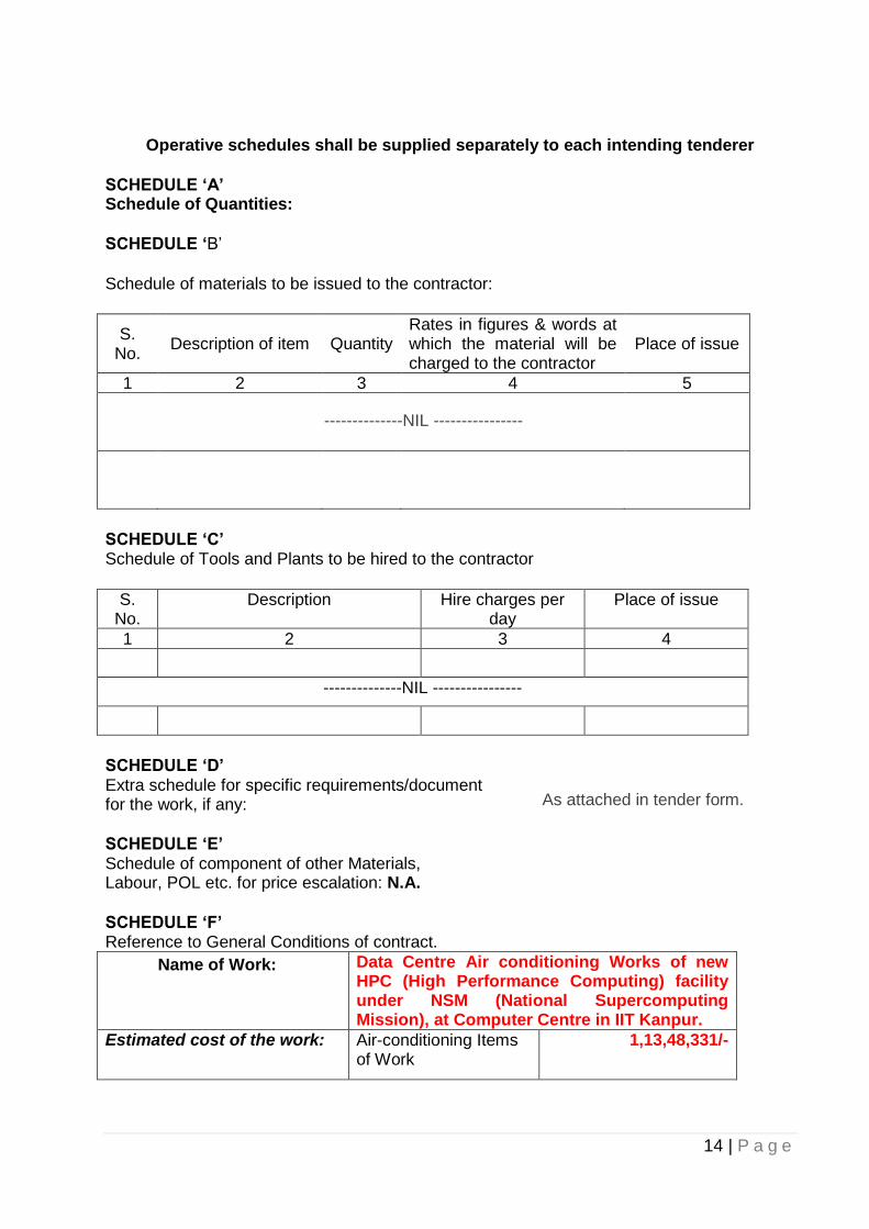


![INDEX [] Documents.pdfINDEX Name of Work: Construction of Office Block at IIT Kanpur Outreach Centre NOIDA (SH: Air-conditioning Works). Sl.No. Description Page Index Page 1 PART-A](https://static.documents.pub/doc/80x56/5af4ccac7f8b9a4d4d8e2726/index-name-of-work-construction-of-office-block-at-iit-kanpur-outreach-centre.jpg)


