+ All Categories
Home > Documents > INDEX OF REVISIONS REV. DESCRIPTION AND/OR ......P&ID - Piping and Instrument Diagram PLC -...

INDEX OF REVISIONS REV. DESCRIPTION AND/OR ......P&ID - Piping and Instrument Diagram PLC -...

Date post: 23-Apr-2020
Category:
Upload: others
View: 23 times
Download: 1 times
Share this document with a friend
61
TECHNICAL SPECIFICATION No. I-ET-3000.00-1200-940-P4X-001 CLIENT: SHEET: 1 of 61 JOB: -- AREA: DP&T-SUP TITLE: TAGGING PROCEDURE FOR PRODUCTION UNITS DESIGN NP-1 ESUP MICROSOFT WORD / V. 2016 / I-ET-3000.00-1200-940-P4X-001_0.DOC INDEX OF REVISIONS REV. DESCRIPTION AND/OR REVISED SHEETS 0 ORIGINAL ISSUE REV. 0 REV. A REV. B REV. C REV. D REV. E REV. F REV. G REV. H DATE SEP/06/18 DESIGN ESUP EXECUTION ERNANI CHECK ISABELA APPROVAL MEYRELLES INFORMATION IN THIS DOCUMENT IS PROPERTY OF PETROBRAS, BEING PROHIBITED OUTSIDE OF THEIR PURPOSE FORM OWNED TO PETROBRAS N-381 REV. L PRELIMINARY
Transcript

TECHNICAL SPECIFICATION No.

I-ET-3000.00-1200-940-P4X-001 CLIENT:

SHEET:

1 of

61 JOB:

--

AREA:

DP&T-SUP

TITLE:

TAGGING PROCEDURE FOR PRODUCTION UNITS DESIGN

NP-1

ESUP

MICROSOFT WORD / V. 2016 / I-ET-3000.00-1200-940-P4X-001_0.DOC

INDEX OF REVISIONS

REV. DESCRIPTION AND/OR REVISED SHEETS

0

ORIGINAL ISSUE

REV. 0 REV. A REV. B REV. C REV. D REV. E REV. F REV. G REV. H

DATE SEP/06/18

DESIGN ESUP

EXECUTION ERNANI

CHECK ISABELA

APPROVAL MEYRELLES

INFORMATION IN THIS DOCUMENT IS PROPERTY OF PETROBRAS, BEING PROHIBITED OUTSIDE OF THEIR PURPOSE

FORM OWNED TO PETROBRAS N-381 REV. L

PRELIMIN

ARY

TECHNICAL SPECIFICATION No.

I-ET-3000.00-1200-940-P4X-001 REV.

0 AREA:

SHEET: 2 of

61 TITLE:

TAGGING PROCEDURE FOR PRODUCTION UNITS DESIGN

NP-1

ESUP

ESUP PARTICIPANTS

1. Bernardo Torres de Mattos – Hull Structure

2. Daniela da Câmara Pacheco - Safety

3. Ernani Luis Sztajnbok – Coordinator and HVAC

4. Filipe Castello da Costa Beltrão Diniz – Engineering Design Automation

5. Gabriel Taffarel e Silva – Marine Systems

6. Jansen Martins Lopes – Process

7. Marcelo Borges Peres - Electrical

8. Paulo Pastore – Topside Structure

9. Pedro Jacinto Vivas Ponte – Piping and Valves

10. Rafael José Gonçalves Pereira – Automation and Instrumentation

11. Robson dos Santos Gonçalves – Telecommunication

PRELIMIN

ARY

TECHNICAL SPECIFICATION No.

I-ET-3000.00-1200-940-P4X-001 REV.

0 AREA:

SHEET: 3 of

61 TITLE:

TAGGING PROCEDURE FOR PRODUCTION UNITS DESIGN

NP-1

ESUP

TABLE OF CONTENTS

1. OBJECTIVE .............................................................................................................................................. 4 2. ABBREVIATION AND ACRONYMS ......................................................................................................... 5 3. REFERENCE DOCUMENTS .................................................................................................................... 6 4. PROCESS ................................................................................................................................................. 7 5. PIPING ...................................................................................................................................................... 8 6. SAFETY .................................................................................................................................................. 16 7. MECHANICAL ......................................................................................................................................... 17 8. HVAC ...................................................................................................................................................... 18 9. AUTOMATION ........................................................................................................................................ 23 10. ELECTRICAL .......................................................................................................................................... 47 11. STRUCTURE .......................................................................................................................................... 48 11.1. TOPSIDE STRUCTURAL ELEMENTS ............................................................................................... 48 11.2. HULL STRUCTURAL ELEMENTS ..................................................................................................... 50 12. MARINE SYSTEMS ................................................................................................................................ 56 13. TELECOMUNICATION ........................................................................................................................... 57 14. 3D MODEL (ALL DISCIPLINES) ............................................................................................................. 58

PRELIMIN

ARY

TECHNICAL SPECIFICATION No.

I-ET-3000.00-1200-940-P4X-001 REV.

0 AREA:

SHEET: 4 of

61 TITLE:

TAGGING PROCEDURE FOR PRODUCTION UNITS DESIGN

NP-1

ESUP

1. OBJECTIVE

This technical specification establishes the conditions required for the identification of different

items and components belonging to a Production Unit.

This document covers the following disciplines: Process. Piping, Mechanical, HVAC,

Automation, Electrical, Structure, Marine Systems and Telecommunication.

It is expected, as a benefit of the application of the this tagging standard, the possibility of better

identification of interferences, extraction of consistency reports between P&IDs, D&IDs and 3D

model, extraction of reports in the basic design phase and Construction & Assembly, and

benefits in the operation phase, since most of the elements will be traceable.

This Standard is not mandatory for the identification of any item introduced in existent units,

which shall be identified according to rules established by PETROBRAS, on a case-by-case

basis (preferably following previously existing unit rules).

PRELIMIN

ARY

TECHNICAL SPECIFICATION No.

I-ET-3000.00-1200-940-P4X-001 REV.

0 AREA:

SHEET: 5 of

61 TITLE:

TAGGING PROCEDURE FOR PRODUCTION UNITS DESIGN

NP-1

ESUP

2. ABBREVIATION AND ACRONYMS

Tagging – act of identification of an equipment or component

3D model – Database which describes engineering objects defining their position, shape,

dimensions and properties

ADV - Automatic Deluge Valve

AFDS - Addressable Fire Detection System

BDV - Blowdown Valve

CAE - Computer Aided Engineering

D&ID - Duct and Instrument Diagram

E&P - Exploration and Production

ESD-2 - Emergency Shutdown level 2

FPSO - Floating Production, Storage and Offloading

HPU - Hydraulic Power Unit

HVAC - Heating, Ventilation and Air Conditioning

IS - Intrinsically Safe

MCT - Multi-Cable-Transit

JB - Junction Box

P&ID - Piping and Instrument Diagram

PLC - Programmable Logic Controller

PSV - Pressure Safety Valve

SDV - Shutdown Valve

PRELIMIN

ARY

TECHNICAL SPECIFICATION No.

I-ET-3000.00-1200-940-P4X-001 REV.

0 AREA:

SHEET: 6 of

61 TITLE:

TAGGING PROCEDURE FOR PRODUCTION UNITS DESIGN

NP-1

ESUP

3. REFERENCE DOCUMENTS

3.1. Petrobras Standards

NI-1521 - Identification of Industrial Equipment

NI-1710 - Coding of Technical Engineering Documents

3.2. Petrobras Documents

DR-ENGP-I-1.1 - Piping Standard and Material for Oil Production and Process Facilities

I-ET-3010.XX-1200-200-P4X-XXX – Piping Specification for Topside and Piping

Specification for Hull 1

I-ET-3010.00-1400-140-P4X-001 – Structural Plates and Profiles Catalogue

I-ET-3010.00-5140-700-P4X-001 - Specification for Electrical Design for Offshore Units

3.3. Other Documents

ISA-5.1 2009 – Instrumentation Symbols and Identification

API RP 14C – Recommended Practice for Analysis, Design, Installation and Testing of

Basic Surface Safety Systems for Offshore Production Platforms

1 Technical Specification issued for a specific Project for Topside and for Hull

PRELIMIN

ARY

TECHNICAL SPECIFICATION No.

I-ET-3000.00-1200-940-P4X-001 REV.

0 AREA:

SHEET: 7 of

61 TITLE:

TAGGING PROCEDURE FOR PRODUCTION UNITS DESIGN

NP-1

ESUP

4. PROCESS

Identification TAGs of Process equipment shall be defined according to PETROBRAS standards

NI-1521 - Identification of Industrial Equipment and considering alternative of Annex C of NI-

1710 - Coding of Technical Engineering Documents for the Area.

This Standard establishes the conditions required for the identification of equipment belonging to

industrial facilities of PETROBRAS.

This Standard does not apply to measurement and control instruments nor to piping items. For

these items, refer to Automation and Piping sections.

In all documents pertaining to an industrial equipment or in documents where reference is made

to an industrial equipment, the industrial equipment shall be identified according to NI-1521.

PRELIMIN

ARY

TECHNICAL SPECIFICATION No.

I-ET-3000.00-1200-940-P4X-001 REV.

0 AREA:

SHEET: 8 of

61 TITLE:

TAGGING PROCEDURE FOR PRODUCTION UNITS DESIGN

NP-1

ESUP

5. PIPING

5.1. Piping Tagging:

Piping tagging shall be according to the last version of the piping specification document issued

during basic design phase: Topside Piping Specification and Piping Specification for Hull.

5.2. Piping fittings Tagging:

Piping fittings are:

Valves

Special Items

Piping fittings Tagging shall be according to the following procedure:

5.2.1. Valves:

Two different groups of valves shall be used for tagging named: instrumented valves and non-

instrumented valves

1.1.1.1 Instrumented Valves

For more information see chapter 9-AUTOMATION

1.1.1.2 Non-instrumented Valves

For non-instrumented valves tagging shall be according to the following procedure.

(A)(-)(B)(C)

Where:

(A) = “VALV”

(-) =hyphen

(B) = area/system (according to NI-1710, Annex C) and

(C) = sequential code (three numbers)

Example of non-instrumented valve tag: VALV–1254001

VALV: Not instrumented valve

1254: CO2 gas injection system

001: Sequential Numbering

5.2.2. Special Items

Special items are divided in the following groups:

5.2.2.1. Expansion Joints

Tagging for expansion joints shall be as following.

(A)(-)(B)(C)

Where:

(A) = “JE”

(-) =hyphen

(B) = area/system (according to NI-1710, Annex C) and

PRELIMIN

ARY

TECHNICAL SPECIFICATION No.

I-ET-3000.00-1200-940-P4X-001 REV.

0 AREA:

SHEET: 9 of

61 TITLE:

TAGGING PROCEDURE FOR PRODUCTION UNITS DESIGN

NP-1

ESUP

(C) = sequential code (three numbers)

Example of an expansion joint tag: JE–1254001

JE: Expansion Joint

1254: CO2 gas injection system

001: Sequential Numbering

5.2.2.2. Figure 8, Spacers, Paddles, Restriction Orifice and Orifice Plate

For these items, tagging shall be as the following procedure:

(A)(-)(B)(-)(C)(-)(D)(-)(E)

Where:

(A)= “FIG”

(-)=hyphen

(B)= Abbreviation, according to FIG-8: Figure 8

P: Process fluid (non-corrosive hydrocarbon)

B10: pipe SPEC

001: Sequential Numbering

Table 5.1.

(-)=hyphen

(C)= service, according to the current piping specification document for Topside and Hull;

(-)=hyphen

(D)= pipe SPEC, according to the current piping specification document for Topside and Hull;

(-)=hyphen

(E)= sequential code (three numbers)

Example of a Figure 8 tag: FIG-8-P-B10-001

FIG-8: Figure 8

P: Process fluid (non-corrosive hydrocarbon)

B10: pipe SPEC

001: Sequential Numbering

Table 5.1- Piping components type abbreviation

Piping Components Abbreviation

Figure 8 8

Spacer E

Paddle R

Restriction Orifice O

Orifice Plate D

PRELIMIN

ARY

TECHNICAL SPECIFICATION No.

I-ET-3000.00-1200-940-P4X-001 REV.

0 AREA:

SHEET: 10 of

61 TITLE:

TAGGING PROCEDURE FOR PRODUCTION UNITS DESIGN

NP-1

ESUP

5.2.2.3. Quick Connections

Quick connection tagging shall be as the following procedure:

(A)(-)(B)(-)(C)(-)(D)(-)(E)

(A) = Quick connector abbreviation, according to Table 5.2

(-) = hyphen

(B) = Maximum connector working pressure [bar unit] (three digits);

(-) = hyphen

(C) = service, according to the current piping specification document for Topside and Hull;

(-) = hyphen

(D) = pipe SPEC, according to the current piping specification document for Topside and Hull;

(-) = hyphen

(E) = sequential code (three numbers)

Example of a quick connection tag: QC-020-P-B10-001

QC: Quick Connect

020: Maximum connector pressure equal to 20 bar

P: Process fluid (non-corrosive hydrocarbon)

B10: pipe SPEC

001: Sequential Numbering

Table 5.2 – Quick connection abbreviation

Quick Connector Type Abbreviation

Chiksan CS

Storz ST

Quick Connect QC

Camlock CL

Swivel Joint SJ

Others ER

5.2.2.4. Strainers

For strainers, tagging shall be as the following procedure:

(A)(-)(B)(-)(C)(-)(D)(-)(E)

Where:

(A) = Strainer type abbreviation, according to Table 5.3.

(-) = hyphen

(B) = service, according to the current piping specification document for Topside and Hull;

PRELIMIN

ARY

TECHNICAL SPECIFICATION No.

I-ET-3000.00-1200-940-P4X-001 REV.

0 AREA:

SHEET: 11 of

61 TITLE:

TAGGING PROCEDURE FOR PRODUCTION UNITS DESIGN

NP-1

ESUP

(-) =hyphen

(C) = pipe SPEC, according to the current piping specification document for Topside and Hull;

(-) =hyphen

(D) = pipe sequential number according to the piping tag.

(-) =hyphen

(E) = sequential code (three numbers)

Example of a strainer tag: FB-P-B10-005-002

FB: Conical strainer

P: Process fluid (non-corrosive hydrocarbon)

B10: pipe SPEC

005: pipe sequential numbering (according to pipe tag)

001: sequential numbering

Table 5.3- Strainers type abbreviation

Strainer Type Abbreviation

Conical FB

“Y” FY

“T” FT

5.2.2.5. Connections

For connections, tagging shall be as the following procedure:

(A)(-)(B)(-)(C)(-)(D)

Where:

(A) = connection type abbreviation, according to Table 5.4.

(-) =hyphen

(B) = Area, according to the last revision of NI-1710 (Annex C);

(-) =hyphen

(C) = sequential code (three numbers);

(-) =hyphen

(D) = Option (1 or 2)

*NOTES

Option is “1” or “2” for joints pair.

Connections shall be tagged for torque control report.

Example of a connection tag: JF-1254-001-1

JF: Flanged Connection

1254: CO2 gas injection system

001: Sequential Numbering

PRELIMIN

ARY

TECHNICAL SPECIFICATION No.

I-ET-3000.00-1200-940-P4X-001 REV.

0 AREA:

SHEET: 12 of

61 TITLE:

TAGGING PROCEDURE FOR PRODUCTION UNITS DESIGN

NP-1

ESUP

1: flange number one

Table 5.4- Connection type abbreviation

Connection Type Abbreviation

Flanged Connection JF

Clamp Connection JA

Compact Flange JC

5.2.2.6. Hose

Hose shall be tagged according to the following procedure:

(A)(-)(B)(-)(C)

Where:

(A) = “MF”

(-) = hyphen

(B) = Area, according to the last revision of NI-1710 (Annex C);

(-) = hyphen

(C) = sequential code (three numbers);

Example of a hose tag: MF-1254-001

MF: Hose

1254: CO2 gas injection system

001: Sequential Numbering

5.2.2.7. Spools

Spools shall be tagged according to the following procedure:

(A)(-)(B)(-)(C)

Where:

(A) = “CR”

(-) = hyphen

(B) = Area according to the last revision of NI-1710 (Annex C);

(-) = hyphen

(C) = sequential code (three numbers);

Example of a spool tag: CR-1254-001

CR: Spool

1254: CO2 gas injection system

001: Sequential Numbering

PRELIMIN

ARY

TECHNICAL SPECIFICATION No.

I-ET-3000.00-1200-940-P4X-001 REV.

0 AREA:

SHEET: 13 of

61 TITLE:

TAGGING PROCEDURE FOR PRODUCTION UNITS DESIGN

NP-1

ESUP

5.2.2.8. Others Items

Piping special items (not listed previously) shall be tagged according the following procedure:

(A)(-)(B)(C)

Where:

(A) = ESP;

(-)= hyphen

(B)= area/system (according to NI-1710, Annex C) and

(C) = sequential code (three numbers)

Example of special item tag: ESP–1254001

ESP: Special Item

1254: CO2 gas injection system

001: Sequential Numbering.

5.3. Tagging procedure for topsides pipe supports

For topsides pipe supports, tagging shall be according to the following procedure:

(A)(-)(B)(-)(C)

Where:

(A) = Support type (abbreviation); according to Table 5.5.

(-) = hyphen

(B) = Support Module Location (abbreviation);

(-) = hyphen

(C) = Sequential code (three digits)

Example of topside pipe support: SP–M07-001

SP: Standard Support

M07: FPSO Module 07

001: Sequential Numbering.

*NOTES:

For FPSO modules (including pipe-rack), the abbreviation shall be composed by the

letter M and two sequential digits.

Table 5.5- Support type abbreviation

Support Type Abbreviation

Standard Support SP

Special Support SE

Spring Support SM

PRELIMIN

ARY

TECHNICAL SPECIFICATION No.

I-ET-3000.00-1200-940-P4X-001 REV.

0 AREA:

SHEET: 14 of

61 TITLE:

TAGGING PROCEDURE FOR PRODUCTION UNITS DESIGN

NP-1

ESUP

5.4. Tagging procedure for hull pipe support

For hull pipe supports, tagging shall be according to the following procedure:

(A)(-)(B)(-)(C)(-)(D)(-)(E)

Where:

(A) = Support type (abbreviation); according to Table 5.5.

(-) = hyphen

(B) = Hull Region (abbreviation); according to Table 5.6 and Table 5.7.

(-) = hyphen

(C) = Frame number (three digits), according to Hull design

(-) = hyphen

(D) = Hull side;

(-) = hyphen

(E) = Sequential code (three digits)

Table 5.6 – Hull Region Abbreviation

Hull Region Abbreviation

Poop Deck and Aft Region AR

Accomodation AC

Main Deck MD

Fore Castle Deck and Fwd Region FR

Engine Room ER

Pump Room / Cofferdam PR

Cargo Area CA

Fwd Peak Tank FP

Figure 5.1 - Hull Regions

PRELIMIN

ARY

TECHNICAL SPECIFICATION No.

I-ET-3000.00-1200-940-P4X-001 REV.

0 AREA:

SHEET: 15 of

61 TITLE:

TAGGING PROCEDURE FOR PRODUCTION UNITS DESIGN

NP-1

ESUP

Example of hull pipe support: SP–MD-125-PS-001

SP: Standard Support

MD: FPSO Main Deck

125: Frame number

PS: Portside

001: Sequential (three numbers).

Table 5.7 – Hull Side

Hull Side Abbreviation

Portside PS

Starboard SB

PRELIMIN

ARY

TECHNICAL SPECIFICATION No.

I-ET-3000.00-1200-940-P4X-001 REV.

0 AREA:

SHEET: 16 of

61 TITLE:

TAGGING PROCEDURE FOR PRODUCTION UNITS DESIGN

NP-1

ESUP

6. SAFETY

Identification TAGs of Process equipment shall be defined according to PETROBRAS standards

NI-1521 - Identification of Industrial Equipment and considering alternative of Annex C of NI-

1710 - Coding of Technical Engineering Documents for the area.

This Standard establishes the conditions required for the identification of equipment belonging to

industrial facilities of PETROBRAS.

This Standard does not apply to measurement and control instruments nor to piping items. For

these items, refer to Automation and Piping sections.

In all documents pertaining to an industrial equipment or in documents where reference is made

to an industrial equipment, the industrial equipment shall be identified according to NI-1521.

PRELIMIN

ARY

TECHNICAL SPECIFICATION No.

I-ET-3000.00-1200-940-P4X-001 REV.

0 AREA:

SHEET: 17 of

61 TITLE:

TAGGING PROCEDURE FOR PRODUCTION UNITS DESIGN

NP-1

ESUP

7. MECHANICAL

Identification TAGs of Mechanical equipment shall be defined according to PETROBRAS

standards NI-1521 - Identification of Industrial Equipment and considering alternative of Annex

C of NI-1710 - Coding of Technical Engineering Documents for the area.

This Standard establishes the conditions required for the identification of equipment belonging to

industrial facilities of PETROBRAS.

This Standard does not apply to measurement and control instruments nor to piping items. For

these items, refer to Automation and Piping sections.

In all documents pertaining to an industrial equipment or in documents where reference is made

to an industrial equipment, the industrial equipment shall be identified according to NI-1521.

PRELIMIN

ARY

TECHNICAL SPECIFICATION No.

I-ET-3000.00-1200-940-P4X-001 REV.

0 AREA:

SHEET: 18 of

61 TITLE:

TAGGING PROCEDURE FOR PRODUCTION UNITS DESIGN

NP-1

ESUP

8. HVAC

8.1. Equipment

Identification TAGs of HVAC equipment shall be defined according to PETROBRAS standards

NI-1521 - Identification of Industrial Equipment and considering alternative of Annex C of NI-

1710 - Coding of Technical Engineering Documents for the area.

All observations about process equipment are also valid.

8.2. Ducts

All ducts shall be individually identified by an alphanumeric combination of 6 (six) elements

A-B-C-D-E-F where:

A - Service identification;

B - Served Equipment TAG sequential;

C - Duct section form;

D - Duct material;

E - Duct System - Sequential identification;

F - Duct Run - Sequential identification (only for 3D model);

As detailed in Sections 8.2.1 to 8.2.6.

8.2.1. Service Identification

AC: Air Conditioning supply;

RTN: Air Conditioning machines return;

AE: Outside air intake for air conditioning machines;

INS: Fan supply;

EXT: Fan exhaust;

ENT: Duct branch, for air intake, not connected to HVAC equipment;

SAI: Duct branch, for exhaust, not connected to HVAC equipment

8.2.2. Sequential identification of the equipment (or redundant equipment group) served by the

system. When dealing with air intake or exhaust duct branches, not connected to any HVAC

equipment, this item shall not be fulfilled.

8.2.3. Duct section form identification

CIRC: circular;

RET: rectangular;

OV: oval.

8.2.4. Duct Material:

SS: stainless steel;

CS: galvanized carbon steel.

PRELIMIN

ARY

TECHNICAL SPECIFICATION No.

I-ET-3000.00-1200-940-P4X-001 REV.

0 AREA:

SHEET: 19 of

61 TITLE:

TAGGING PROCEDURE FOR PRODUCTION UNITS DESIGN

NP-1

ESUP

8.2.5. Sequential: alphanumeric combination of 3 digits, as defined in item 8.3.

8.2.6. Sequential: alphanumeric combination of 3 digits, as defined in item 8.4.

Examples:

ENT-CIRC-CS-102

SAI-CIRC-CS-123 PRELIMIN

ARY

TECHNICAL SPECIFICATION No.

I-ET-3000.00-1200-940-P4X-001 REV.

0 AREA:

SHEET: 20 of

61 TITLE:

TAGGING PROCEDURE FOR PRODUCTION UNITS DESIGN

NP-1

ESUP

VT001-OV-CS-017

EXT002-CIRC-CS-017

PRELIMIN

ARY

TECHNICAL SPECIFICATION No.

I-ET-3000.00-1200-940-P4X-001 REV.

0 AREA:

SHEET: 21 of

61 TITLE:

TAGGING PROCEDURE FOR PRODUCTION UNITS DESIGN

NP-1

ESUP

8.3. Rules for Sequential definition (D&IDs)

8.3.1. For ducts connected to supply fans

­ sequential 001 shall start at fan discharge

­ For redundant equipment, sequential 001 shall be used for both “A” equipment and “B”

equipment initial duct

­ Sequential number 001 shall be the same for one duct line chosen that will finish in an

ambient

­ Every branch from the 001 duct system shall have a new sequential number that will

represent also a duct line chosen that will finish in an ambient

­ And so the rule will be applied to all branches

­ After defining sequential numbers for discharge ducts, the same procedure shall be used

for fan suction branches, respecting the last sequential used for supply fans

8.3.2. For ducts connected to exhaust fans

­ sequential 001 shall start at fan suction

­ For redundant equipment, sequential 001 shall be used for both “A” equipment and “B”

equipment initial duct

­ Sequential number 001 shall be the same for one duct line chosen that will finish in an

ambient

­ Every branch from the 001 duct system shall have a new sequential number that will

represent also a duct line chosen that will finish in an ambient

­ And so the rule will be applied to all branches

­ After defining sequential numbers for suction ducts, the same procedure shall be used for

fan discharge branches, respecting the last sequential used for supply fans

8.3.3. For ducts connected to air condition supply system

­ sequential 001 shall start at machine discharge

­ For redundant equipment, sequential 001 shall be used for both “A” equipment and “B”

equipment initial duct

­ Sequential number 001 shall be the same for one duct line chosen that will finish in an

ambient

­ Every branch from the 001 duct system shall have a new sequential number that will

represent also a duct line chosen that will finish in an ambient

­ And so the rule will be applied to all branches

PRELIMIN

ARY

TECHNICAL SPECIFICATION No.

I-ET-3000.00-1200-940-P4X-001 REV.

0 AREA:

SHEET: 22 of

61 TITLE:

TAGGING PROCEDURE FOR PRODUCTION UNITS DESIGN

NP-1

ESUP

8.3.4. For ducts connected to air condition return system

­ sequential 001 shall start at machine mix section

­ For redundant equipment, sequential 001 shall be used for both “A” equipment and “B”

equipment initial duct

­ Sequential number 001 shall be the same for one duct line chosen that will finish in an

ambient

­ Every branch from the 001 duct system shall have a new sequential number that will

represent also a duct line chosen that will finish in an ambient

­ And so the rule will be applied to all branches

8.3.5. For ducts connected to air condition outside air system

­ sequential 001 shall start at machine mix section (when available) or air intake

­ For redundant equipment, sequential 001 shall be used for both “A” equipment and “B”

equipment initial duct

­ Sequential number 001 shall be the same for one duct line chosen that will finish at air

intake

8.3.6. For duct branch, from air intake, not connected to HVAC equipment

­ sequential 001 shall start at air intake outside ambient

8.3.7. For duct branch, from exhaust, not connected to HVAC equipment

­ sequential 001 shall start at air intake inside ambient

8.4. Rules for Sequential definition (3D Model)

Any duct system defined in D&IDs may be splited in as many as necessary duct runs

which will have a sequential number as defined in item 8.2.

Sequential number shall be changed for different spools (branches between flanges).

Sequential number shall be changed after direction change fittings.

Sequential number shall be changed after branch fittings.

Sequential numbers for transition fittings shall follow the same rules of the ducts where

they are assembled.

PRELIMIN

ARY

TECHNICAL SPECIFICATION No.

I-ET-3000.00-1200-940-P4X-001 REV.

0 AREA:

SHEET: 23 of

61 TITLE:

TAGGING PROCEDURE FOR PRODUCTION UNITS DESIGN

NP-1

ESUP

9. AUTOMATION

9.1. GENERAL

The purpose of this chapter is to establish the systematic that shall be adopted for the

identification (Tagging, TAG) of all instrumentation items.

Prior to describing the TAGs, this chapter contains a section describing the existing and

the adopted sequential tagging logic.

All TAGs shall be unique, i.e., the same TAG shall not be used to describe different

equipment, instruments, mechanical components, and so on.

Package-units’ instruments shall also abide to the rules of this document.

9.2. Sequential numbering logics

The sequential number is a set of 3 digits present in every loop and every instrument

TAG. There are 2 possible ways to choose these digits, described in ISA 5.1 R1992. They

are presented below.

9.2.1. Serial numbering

This logic states that the sequential number shall never be the same for every loop,

regardless of the measured variable (first letter of the prefix).

Example:

Table 9.1 - Serial numbering logic

LOOP Loop Instruments

T- 1223001 TIT-1223001, TV-1223001, TIC-1223001, TSH-1223001

P-1223002A PIT-1223002A, PSH-1223002A, PSHH-1223002A

P-1223002B PIT-1223002B, PSH-1223002B, PSHH-1223002B

L-1223003 LIT-1223003 LSH-1223003

T- 1223004 TIT-1223004, TV-1223004, TIC-1223004,TSH-1223004

Note that:

the sequential numbers do not repeat themselves (except when used in combination with

other letters)

o In other words, when the sequential number is used with a certain measured variable,

it may not be used again with a different measured variable.

o In the example above: Once the loop T-1223001 has been created with the TIT-

1223001 and other instruments in it, then the number 1223001 shall not be used for

other variables (pressure, flow, and so on). That’s why the first pressure loop has a

sequential number of 1223002.

Physical and virtual instruments shall have the same sequential number as the loop to

which they belong.

PRELIMIN

ARY

TECHNICAL SPECIFICATION No.

I-ET-3000.00-1200-940-P4X-001 REV.

0 AREA:

SHEET: 24 of

61 TITLE:

TAGGING PROCEDURE FOR PRODUCTION UNITS DESIGN

NP-1

ESUP

9.2.2. Parallel numbering

This logic allows the use of the same sequential number for different measured variables

(first letter of the Prefix).

Example:

Table 9.2 - Parallel tagging logic

LOOP Loop Instruments

T- 1223001 TIT-1223001, TV-1223001, TIC-1223001,TSH 1223001

P-1223001A PIT-1223001A PSH-1223001A, PSHH-1223001A

P-1223001B PIT-1223001B PSH-1223001B, PSHH-1223001B

L-1223001 LIT-1223001, LSH-1223001

T- 1223002 TIT-1223002, TV-1223002, TIC-1223002,TSH 1223002

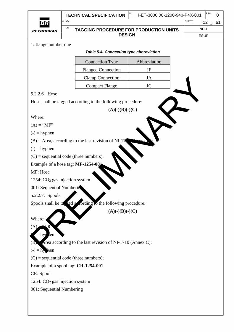
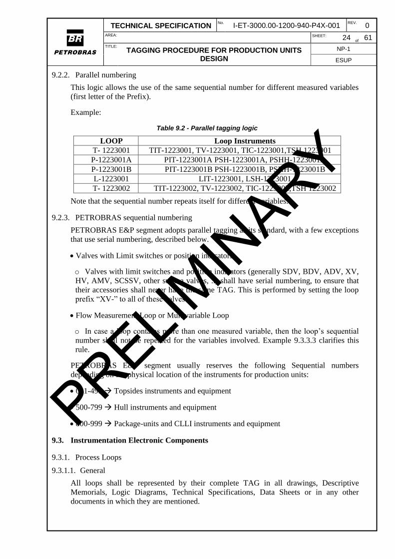
Note that the sequential number repeats itself for different variables.

9.2.3. PETROBRAS sequential numbering

PETROBRAS E&P segment adopts parallel tagging as its standard, with a few exceptions

that use serial numbering, described below.

Valves with Limit switches or position indicators

o Valves with limit switches and position indicators (generally SDV, BDV, ADV, XV,

HV, AMV, SCSSV, other subsea valves, ..) shall have serial numbering, to ensure that

their accessories shall never have the same TAG. This is performed by setting the loop

prefix “XV-” to all of these valves.

Flow Measurement Loop or Multivariable Loop

o In case a loop contains more than one measured variable, then the loop’s sequential

number shall not be repeated for the variables involved. Example 9.3.3.3 clarifies this

rule.

PETROBRAS E&P segment usually reserves the following Sequential numbers

depending on the physical location of the instruments for production units:

001-499 Topsides instruments and equipment

500-799 Hull instruments and equipment

800-999 Package-units and CLLI instruments and equipment

9.3. Instrumentation Electronic Components

9.3.1. Process Loops

9.3.1.1. General

All loops shall be represented by their complete TAG in all drawings, Descriptive

Memorials, Logic Diagrams, Technical Specifications, Data Sheets or in any other

documents in which they are mentioned.

PRELIMIN

ARY

TECHNICAL SPECIFICATION No.

I-ET-3000.00-1200-940-P4X-001 REV.

0 AREA:

SHEET: 25 of

61 TITLE:

TAGGING PROCEDURE FOR PRODUCTION UNITS DESIGN

NP-1

ESUP

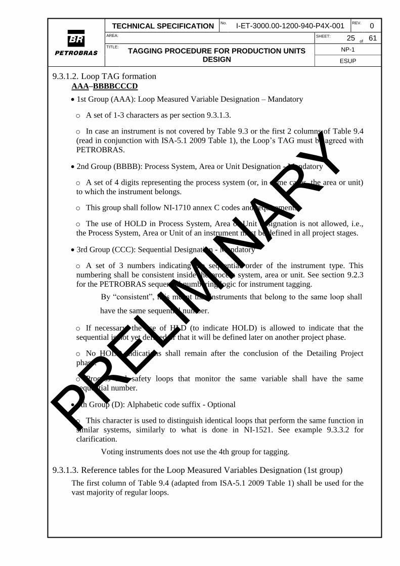
9.3.1.2. Loop TAG formation AAA–BBBBCCCD

1st Group (AAA): Loop Measured Variable Designation – Mandatory

o A set of 1-3 characters as per section 9.3.1.3.

o In case an instrument is not covered by Table 9.3 or the first 2 columns of Table 9.4

(read in conjunction with ISA-5.1 2009 Table 1), the Loop’s TAG must be agreed with

PETROBRAS.

2nd Group (BBBB): Process System, Area or Unit Designation - Mandatory

o A set of 4 digits representing the process system (or, in some cases, the area or unit)

to which the instrument belongs.

o This group shall follow NI-1710 annex C codes and requirements.

o The use of HOLD in Process System, Area or Unit designation is not allowed, i.e.,

the Process System, Area or Unit of an instrument must be defined in all project stages.

3rd Group (CCC): Sequential Designation - Mandatory

o A set of 3 numbers indicating the sequential order of the instrument type. This

numbering shall be consistent inside the process system, area or unit. See section 9.2.3

for the PETROBRAS sequential numbering logic for instrument tagging.

By “consistent”, it is meant that instruments that belong to the same loop shall

have the same sequential number.

o If necessary, the use of HLD (to indicate HOLD) is allowed to indicate that the

sequential is not yet defined or that it will be defined later on another project phase.

o No HOLD indications shall remain after the conclusion of the Detailing Project

phase.

o Process and safety loops that monitor the same variable shall have the same

sequential number.

4th Group (D): Alphabetic code suffix - Optional

o This character is used to distinguish identical loops that perform the same function in

similar systems, similarly to what is done in NI-1521. See example 9.3.3.2 for

clarification.

Voting instruments does not use the 4th group for tagging.

9.3.1.3. Reference tables for the Loop Measured Variables Designation (1st group)

The first column of Table 9.4 (adapted from ISA-5.1 2009 Table 1) shall be used for the

vast majority of regular loops.

PRELIMIN

ARY

TECHNICAL SPECIFICATION No.

I-ET-3000.00-1200-940-P4X-001 REV.

0 AREA:

SHEET: 26 of

61 TITLE:

TAGGING PROCEDURE FOR PRODUCTION UNITS DESIGN

NP-1

ESUP

However, PETROBRAS E&P segment complements ISA notation by using a set of

special combination of characters to discern loops containing subsea valves and to

distinguish loops containing on-off valves according to their function. These set of

characters were based on API RP 14C and are shown on Table 9.3.

Table 9.3 - Special Loop Measured Variable Designation (1st group) for Loops.

Prefix Loop Type

XV Shutdown Valve Loops

XV Blowdown Valve Loops

XV Deluge Valve Loops

XV Annular Master Valve Loops

XV Auxiliary Wing Valve Loops

XV Cross-Over Valve Loops

XV Surface Controlled Subsurface Safety Valve Loops

XV Piggable Cross-Over Valve Loops

PDG Permanent Downhole Gauge Loops

XV Production Master Valve Loops

XV Production Wing Valve Loops

TPT Submarine Pressure and Temperature Transmitter Loops

XV On-Off Valve Loops

XV Limit switch (ZSL/ZSH) of valves Loops

SDVs, BDVs, XVs and any other valves that possess limit switches shall pertain to loops

with a Loop Prefix of XV. This is meant to allow the limit switches to have the same

sequential number as the valves and to ensure that these accessories shall never have the

same TAG in different valves (i.e., valves with limit switches shall have serial numbering,

as per 9.2.1).

Variable modifiers also integrate the loop. Example: differential pressure PDIT-

1223001’s loop shall be PD-1223001.

9.3.2. Process Instruments

9.3.2.1. General

This section covers process instruments. Fire and Gas Detection instruments are covered

in section 9.3.4.

Process instruments shall be represented by their complete TAG in all drawings,

Descriptive Memorials, Logical Diagrams, Technical Specifications, Data Sheets or in

any other documents in which they are mentioned.

9.3.2.2. TAG formation

The instrument TAG is an alphanumeric code composed of six (6) Groups disposed as

below:

AAAAAA–BBBBCCCD–FE

1st Group (AAAAAA): Instrument Measured Variable Designation - Mandatory

o A set of 2-6 characters as per section.

PRELIMIN

ARY

TECHNICAL SPECIFICATION No.

I-ET-3000.00-1200-940-P4X-001 REV.

0 AREA:

SHEET: 27 of

61 TITLE:

TAGGING PROCEDURE FOR PRODUCTION UNITS DESIGN

NP-1

ESUP

o In case an instrument is not covered by Table 9.4 (read in conjunction with ISA-5.1

2009 table 1) and Table 9.5, the instrument’s TAG must be agreed with PETROBRAS.

2nd Group (BBBB): Process system, Area or Unit Designation - Mandatory

o Same as the Loops TAG. See section 9.3.1.2.

3rd Group (CCC): Sequential Designation - Mandatory

o Same as the Loops Sequential Designation. See section 9.3.1.2.

4th Group (D): Alphabetic code suffix - Optional

o Same as the Loops Alphabetic code suffix. See section 9.3.1.2.

o Voting does not use the 4th group for tagging. See the 5th group for voting

arrangements.

o This Group may also be used to distinguish identical instruments that do not belong

to any loop but perform the same function in similar systems, similarly to NI-1521. For

example, manometers or PSVs do not belong to any loop but may have tags such as

PSV-1223001A.

5th Group (E): Numeric code suffix - Optional

o A digit is used to discern, in terms of capacity/range extension or voting, the TAGs of

instruments that perform the same function in the same process system, area or unit.

By voting it is meant that all involved instruments are operating and their output

is compared by the logic solver in order to decide on the final control action.

6th Group (F): Extra character - Optional

o An extra digit or character is used to indicate further redundancies or subdivisions.

For an example, see Section 9.3.3.8.

When the 5th and 6th groups are not used (FE), the last hyphen must be suppressed.

ISA-5.1 2009 Table 1 shall be read in conjunction with Table 9.4 (that shows the

modifications used by Petrobras in ISA-5.1 2009 table 1) in order to TAG the vast

majority of regular instruments. The letters which are not mentioned in Table 9.4 remain

the same as in ISA-5.1 2009 Table 1.

PRELIMIN

ARY

TECHNICAL SPECIFICATION No.

I-ET-3000.00-1200-940-P4X-001 REV.

0 AREA:

SHEET: 28 of

61 TITLE:

TAGGING PROCEDURE FOR PRODUCTION UNITS DESIGN

NP-1

ESUP

Table 9.4 - PETROBRAS changes to ISA-5.1 2009 table 1. Differences from ISA-5.1 2009 are either underlined (PETROBRAS addition) or crossed out (PETROBRAS removal).

First Letter Succeeding letters

Column 1 Column 2 Column 3 Column 4 Column 5

Measured /

Initiating Variable

Variable Modifier

Readout / Passive

Function

Output / Active

Function

Function Modifier

D

Density, Damper (fire and gas, see column 4)

Difference, Differential

Deviation

F Flow, Flow

Rate Ratio

Fire Damper

G Gas Damper

Glass, Gauge, Viewing Device

H Hand High, (Open

Valve)

L Level Light Low, (Closed

Valve)

S Speed,

Frequency Self-Actuated

Safety Switch Stop

M Moisture Middle,

intermediate

V Vibration,

mechanical Analysis

Valve,

Damper, Louver

X Corrosion,

unclassified X-axis

Accessory devices,

unclassified Unclassified Unclassified

Z Position,

Dimension

Z-axis, Safety Instrumented

System

Driver, actuator,

Unclassified final control

element

Some clarifications regarding ISA-5.1 2009 Table 1 and Table 9.4:

Column 4 letter “I” x letter “G”:

o Letter “I” shall be used when the instrument has a local electronic display or for the

display of the variable in the Supervisory system.

o Letter “G” shall be used if the instrument is entirely mechanical (ex: thermometers,

level gauges, manometers)

PRELIMIN

ARY

TECHNICAL SPECIFICATION No.

I-ET-3000.00-1200-940-P4X-001 REV.

0 AREA:

SHEET: 29 of

61 TITLE:

TAGGING PROCEDURE FOR PRODUCTION UNITS DESIGN

NP-1

ESUP

PETROBRAS E&P segment complements ISA notation by using a set of special

combination of characters to discern Subsea valves and to distinguish some valves

according to their function. Many of these set of characters were based on API RP 14C

and are shown on Table 9.5.

Table 9.5 - Special Instrument Measured Variable Designation (1st group) for subsea valves and to some valves related to safety.

Prefix Instrument Type

SDV / SDY Shutdown Valve (V) and its solenoid (Y)

BDV / BDY Blowdown Valve (V) and its solenoid (Y)

ADV / ADY Automatic Deluge Valve (V) and its solenoid (Y)

AMV / AMY Annular Master Valve (V) and its solenoid (Y)

AWV / AWY Auxiliary Wing Valve (V) and its solenoid (Y)

COV / COY Cross-Over Valve (V) and its solenoid (Y)

SCSSV/SCSSY Surface Controlled Subsurface Safety Valve (V)

and its solenoid (Y)

PCOV / PCOY Piggable Cross-Over Valve (V) and its solenoid (Y)

PDG

Permanent Downhole Gauge

(Same notation as Differential pressure gauge, shall be

distinguished by context)

PMV / PMY Production Master Valve (V) and its solenoid (Y)

PWV / PWY Production Wing Valve (V) and its solenoid (Y)

TPT Submarine Pressure and Temperature Transmitter

XV / XY On-Off Valve (V) and its solenoid (Y)

9.3.3. Examples of Process Loops and Instruments

9.3.3.1. Process loops and instruments

Consider the existence of a series of loops in the Oil processing system (1223 as per NI-

1710), composed of the following instruments and valves:

Loop 1:

o A pressure controlled valve;

o A pressure indicator and controller;

o A pressure indicator and transmitter;

Loop 2:

o A Level indicator and transmitter;

o A level indicator and controller;

o A level controlled valve.

Consider other instruments that do not belong to any of the above loops:

o A pressure manometer measuring the same pressure of loop 1;

o A pressure indicator and transmitter measuring a different point;

PRELIMIN

ARY

TECHNICAL SPECIFICATION No.

I-ET-3000.00-1200-940-P4X-001 REV.

0 AREA:

SHEET: 30 of

61 TITLE:

TAGGING PROCEDURE FOR PRODUCTION UNITS DESIGN

NP-1

ESUP

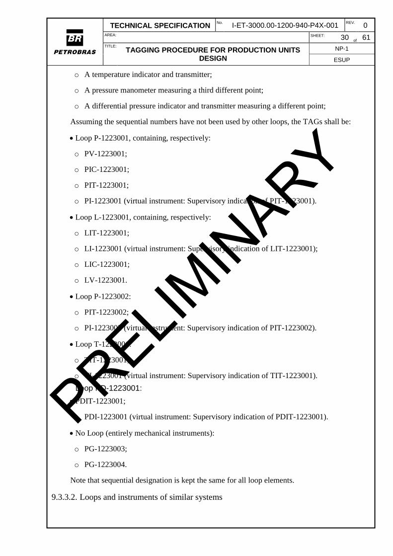
o A temperature indicator and transmitter;

o A pressure manometer measuring a third different point;

o A differential pressure indicator and transmitter measuring a different point;

Assuming the sequential numbers have not been used by other loops, the TAGs shall be:

Loop P-1223001, containing, respectively:

o PV-1223001;

o PIC-1223001;

o PIT-1223001;

o PI-1223001 (virtual instrument: Supervisory indication of PIT-1223001).

Loop L-1223001, containing, respectively:

o LIT-1223001;

o LI-1223001 (virtual instrument: Supervisory indication of LIT-1223001);

o LIC-1223001;

o LV-1223001.

Loop P-1223002:

o PIT-1223002;

o PI-1223002 (virtual instrument: Supervisory indication of PIT-1223002).

Loop T-1223001:

o TIT-1223001;

o TI-1223001 (virtual instrument: Supervisory indication of TIT-1223001).

Loop PD-1223001:

PDIT-1223001;

o PDI-1223001 (virtual instrument: Supervisory indication of PDIT-1223001).

No Loop (entirely mechanical instruments):

o PG-1223003;

o PG-1223004.

Note that sequential designation is kept the same for all loop elements.

9.3.3.2. Loops and instruments of similar systems

PRELIMIN

ARY

TECHNICAL SPECIFICATION No.

I-ET-3000.00-1200-940-P4X-001 REV.

0 AREA:

SHEET: 31 of

61 TITLE:

TAGGING PROCEDURE FOR PRODUCTION UNITS DESIGN

NP-1

ESUP

Suppose pumps B-1223002A/C are arranged in a redundant configuration and that there

are three pressure instruments, each one measuring the discharge pressure of each pump.

Loops and instruments TAGs are:

For pump B-1223002A Loop P-1223003A, containing PIT-1223003A

For pump B-1223002B Loop P-1223003B, containing PIT-1223003B

For pump B-1223002C Loop P-1223003C, containing PIT-1223003C

Another example: assume there is a Thermometer measuring the temperature of each line

associated with the Well Pig Launchers, in the Gas-Lift system (1244, as per NI-1710).

Well Pig Launchers are not redundant, but they perform similar functions in process

system 1244. Well Pig Launchers are tagged LP-1244001A, LP-1244001B, LP-

1244001W. Therefore, the associated thermometers shall have tags TG-1244004A, TG-

1244004B, TG-1244004W, following their respective Well Pig Launcher suffix.

Thermometers have no loop, if they are purely mechanical.

9.3.3.3. Flow metering Loop

Suppose there is a flow metering point in the oil treatment system, which is

composed of an orifice plate, a flow indicator and transmitter, with its associated

pressure and temperature indicators and transmitters. Besides, assume there is a flow

computer associated to this metering point.

Finally, assume there are 2 other totally unrelated sensors in the same system: a Level

indicator and transmitter; and a Pressure indicator and transmitter.

The Loops are:

F-1223001 Flow metering Loop. Composed of:

o FE-1223001

o FIT-1223001

o PIT-1223001

o TIT-1223001

o FQIT-1223001

P-1223002 Unrelated Pressure Loop. Composed of:

o PIT-1223002

L-1223001 Unrelated Level Loop. Composed of:

o LIT-1223001

Note that the flow metering loop has prohibited the use of Loop P-1223001, because loop

F-1223001 already contains a PIT-1223001.

PRELIMIN

ARY

TECHNICAL SPECIFICATION No.

I-ET-3000.00-1200-940-P4X-001 REV.

0 AREA:

SHEET: 32 of

61 TITLE:

TAGGING PROCEDURE FOR PRODUCTION UNITS DESIGN

NP-1

ESUP

9.3.3.4. Split range valves

Suppose that the water outlet from SG-1223001 has a too wide range of operation,

requiring two valves operating in a split range fashion in order to control the water level

inside the vessel.

The TAGs are:

Loop: L-1223001, containing, among others:

o LV-1223001-1;

o LV-1223001-2.

9.3.3.5. Range extension

Assume the flow measurement of the LP Fuel Gas Distribution Header is made by a

senior orifice fitting associated with two flow indicators and transmitters using

differential pressure. The two transmitters are required to extend the measurement range.

The Senior Orifice TAG shall then be FE-5135017 and the associated transmitters shall

have TAGs FIT-5135017-1 and FIT-5135017-2. Each orifice plate shall be tagged FE-

5135017-1, FE-5135017-2, FE-5135017-3, and so on.

9.3.3.6. Valve with several solenoids

Consider an ON-OFF valve that has 2 solenoids: one receives commands from Process

Shutdown PLC and the other from the Fire and Gas PLC.

The TAGs are:

Loop: XV-1233001

o XV-1233001

o XY-1233001-1

o XY-1233001-2

o ZSL-1233001

o ZSH-1233001

9.3.3.7. PSVs

Consider there are three PSVs protecting the downstream side of the Hydraulic Power

Unit pumps (5139 system as per NI-1710) and that they are arranged in the following

fashion:

2 PSVs are required to be in operation for the protection of the system;

1 PSV is spare.

The 3 PSVs are arranged in a redundant configuration. The 3 PSVs shall be tagged:

PSV-5139001A First PSV in operation;

PRELIMIN

ARY

TECHNICAL SPECIFICATION No.

I-ET-3000.00-1200-940-P4X-001 REV.

0 AREA:

SHEET: 33 of

61 TITLE:

TAGGING PROCEDURE FOR PRODUCTION UNITS DESIGN

NP-1

ESUP

PSV-5139001B Second PSV in operation;

PSV-5139001C Spare PSV.

9.3.3.8. Complex PSV example

The objective of this example is to show the allowable extrapolation of the rules

presented in this specification.

Assume there are 2 CO2 compressors, tagged C-UC-1254001A and C-UC-1251001B.

Assume the lines in which these compressors are installed are to be protected with PSVs

and that 2 operating PSVs and 1 spare are needed per Compressor.

The PSVs tags shall be:

For compressor C-UC-1254001A

o PSV-1254001A-A

First PSV of compressor C-UC-1254001A

o PSV-1254001A-B

Second PSV of compressor C-UC-1254001A

o PSV-1254001A-C

Third (Spare) PSV of compressor C-UC-1254001A

For compressor C-UC-1254001B

o PSV-1254001B-A

o PSV-1254001B-B

o PSV-1254001B-C

9.3.3.9. Shutdown valve

Suppose there is a Shutdown valve in main gas compression (system 1231 as per NI-

1710), which has 2 limit switches monitoring its open state and its closed state. This valve

is closed by an ESD-2 signal.

Besides, assume nearby this valve, is a (safety related) pressure monitoring instrument

that generates a HH alarm and a consequent ESD-2.

The TAGs involved shall be:

SDV-1231001 First Shutdown valve of system 1231

SDY-1231001 Solenoid of SDV-1231001

ZSL-1231001 Closure limit switch of SDV-1231001

ZSH-1231001 Open limit switch of SDV-1231001

PIT-1231002 Safety-related Pressure Indicator and transmitter

PRELIMIN

ARY

TECHNICAL SPECIFICATION No.

I-ET-3000.00-1200-940-P4X-001 REV.

0 AREA:

SHEET: 34 of

61 TITLE:

TAGGING PROCEDURE FOR PRODUCTION UNITS DESIGN

NP-1

ESUP

PSHH-1231002 Safety-related Very High Pressure Switch (comparator)

PAHH-1231002 Safety-related Very High Pressure Alarm

9.3.3.10. Voting example

Assume that three Pressure indicators and transmitters have been arranged in a 2oo3

voting system in order to generate an Emergency shutdown (ESD) signal. This signal,

among other actions, closes a Shutdown valve, installed with 2 solenoids arranged in a

1oo2 configuration.

Then the instruments and valve involved shall be tagged:

Loop P-1223001 Generates ESD signal

o PIT-1223001-1

o PIT-1223001-2

o PIT-1223001-3

o PSHH-1223001

o PAHH-1223001

Loop XV-1223001 Receives ESD signal

o SDV-1223001

o SDY-1223001-1

o SDY-1223001-2

o ZSL-1223001

o ZSH-1223001

9.3.3.11. HVAC example

Consider there is a room in module 17 with a fire damper and a gas damper, which are

actuated by solenoids whose actuation logic comes from the Cause and Effect matrix of

the unit.

The TAGs are:

Loop DF-5250101:

o DF-5250101 Fire damper (as per NI-1521).

o DFY-5250101 Solenoid of fire damper DF-5250101.

Loop DG-5250001:

o DG-5250001 Gas tight damper (as per NI-1521).

o DGY-5250001 Solenoid of gas tight damper DG-5250001.

PRELIMIN

ARY

TECHNICAL SPECIFICATION No.

I-ET-3000.00-1200-940-P4X-001 REV.

0 AREA:

SHEET: 35 of

61 TITLE:

TAGGING PROCEDURE FOR PRODUCTION UNITS DESIGN

NP-1

ESUP

9.3.4. Fire and Gas Detection Loops

9.3.4.1. General

Fire and Gas detection loops shall be represented by their complete TAG in all drawings,

descriptive memorials, Logical Diagrams, Technical Specifications, Data sheets or in any

other documents in which they are mentioned.

This section applies only to instruments which are not connected to the Addressable Fire

Detection System (AFDS). AFDS loops go through different modules and zones. AFDS

loops are simply represented by a single letter (A to Z), which is already indicated in their

instruments’ TAG.

9.3.4.2. Loop TAG formation Fire and Gas detectors TAG is an alphanumeric code composed of five (5) Groups

disposed as below:

TTT–GGG–MMM–ZZZ–LXXX

Where:

1st Group (TTT): Detector Designation - Mandatory

o A set of 1-3 characters defining the type of sensor as per Table 9.6.

o In case a detector is not covered by the tables, the instrument’s TAG must be agreed

with PETROBRAS.

Table 9.6 - Detector Designation for non-addressable Fire and Gas Loops.

Prefix Fire and Gas Loop Type

A Gas detector

U Flame/Fire detector

Y Smoke detector

H Manual alarm pushbutton

T Heat (Thermo-velocimetric) detector

2nd Group (-GGG): Gas Type Designation – Mandatory only for AST

o A set of 2-3 characters defining the type of gas measured by the instrument, as per

Table 9.7.

o This field is Mandatory only for gas detectors (AST). For other detectors, this field

does not exist.

Table 9.7 - Allowable gas type designations.

Gas types Fire and Gas instrument Type

CH4 Hydrocarbon gas detector (CH4 or others)

H2S Hydrogen sulfide detector

H2 Hydrogen detector

CO2 Carbonic gas detector

3rd Group (MMM): Module or Hull section – Mandatory

PRELIMIN

ARY

TECHNICAL SPECIFICATION No.

I-ET-3000.00-1200-940-P4X-001 REV.

0 AREA:

SHEET: 36 of

61 TITLE:

TAGGING PROCEDURE FOR PRODUCTION UNITS DESIGN

NP-1

ESUP

A set of 3 characters or digits indicating the module or the hull section where the

instrument is installed.

In case the instrument is located in the Topsides, this field shall be filled with M01, M02,

… with the module where the instrument is installed.

In case the instrument is located in the Hull, this field shall be filled with the 2 character

code of Table 5.6 followed by a number representing the distance to the main deck (main

deck number is 0). Examples:

o AC2: second level of the accommodation

o MD0: Main deck

o ER4: Fourth level of the Engine Room

4th group (ZZZ): Zone – Mandatory

o A set of 3 digits indicating the Zone (for gas sensors) in which the instrument is

installed.

o Zone code is still used for triad sensors.

5th group (L): Addressable Loop – Mandatory for Addressable instruments

o A character representing the Loop in which Addressable fire and gas instruments are

installed.

o Mandatory for Addressable instruments. This field does not exist for instruments

connected directly to the Fire and Gas PLC.

o This field shall be filled with H (for HOLD) during Basic Design engineering phase,

because only during Detailed Engineering Phase the quantities and correct number of

instruments per loop shall be known. At the end of the Detailed Engineering Phase, no

holds shall be present (therefore letter H shall no longer be used).

6th group (XXX): Sequential numbering – mandatory

o A set of 3 digits indicating number of the Loop.

o For addressable instruments, this field shall be equal to the instrument’s sequential

number, because the loop is already represented with the 5th group (addressable loop).

9.3.5. Fire and Gas Detection Instruments

9.3.5.1. General

This chapter defines the identification of Fire and Gas Detection instruments, namely:

Flammable Gas detectors

Toxic Gas detectors

Fire detectors

Smoke detectors

Manual alarm push buttons

PRELIMIN

ARY

TECHNICAL SPECIFICATION No.

I-ET-3000.00-1200-940-P4X-001 REV.

0 AREA:

SHEET: 37 of

61 TITLE:

TAGGING PROCEDURE FOR PRODUCTION UNITS DESIGN

NP-1

ESUP

Heat (Thermo-Velocimetric) detectors

9.3.5.2. TAG formation

Fire and Gas detectors TAG is an alphanumeric code composed of five (5) Groups

disposed as below:

TTT–GGG–MMM–ZZZ–LXXXT–V

Where:

1st Group (TTT): Detector Designation - Mandatory

o A set of 3 characters defining the type of sensor as per Table 9.8.

o In case a detector is not covered by the tables, the instrument’s TAG must be agreed

with PETROBRAS.

Table 9.8 - Detector Designation for instruments related to Fire and Gas detection.

Prefix Fire and Gas instrument Type

AST Gas detector

UST Flame/Fire detector

YST Smoke detector

HSS Manual alarm pushbutton

TST Heat (Thermo-velocimetric) detector

2nd Group (-GGG): Gas Type Designation – Mandatory only for AST

o Same as section 9.3.4.2.

3rd Group (MMM): Module or Hull section – Mandatory

o Same as section 9.3.4.2.

4th group (ZZZ): Zone – Mandatory

o Same as section 9.3.4.2.

5th group (L): Loop – Mandatory for Addressable instruments

o Same as section 9.3.4.2.

6th group (XXX): Sequential numbering – mandatory

o A set of 3 digits indicating number of the instrument

o For addressable instruments, the combination of the 5th group and the 6th group shall

be equal to the address of the addressable instrument. See examples 9.3.6.4 and 9.3.6.6

for clarification.

7th group (T): Subtype indicator - optional

o A letter indicating the subtype of target type sensors as follows:

PRELIMIN

ARY

TECHNICAL SPECIFICATION No.

I-ET-3000.00-1200-940-P4X-001 REV.

0 AREA:

SHEET: 38 of

61 TITLE:

TAGGING PROCEDURE FOR PRODUCTION UNITS DESIGN

NP-1

ESUP

R Receptor;

T Transmitters.

8th group (-V): Voting indicator - optional

o A number indicating the voting instrument for the same detection point (only for

pairs or triads, not applicable for voting zones)

9.3.6. Examples of Fire and Gas Loops and Instruments

9.3.6.1. Point Gas detectors – Triad

Suppose there is an HVAC inlet for the Electric module (M-17 in this example) with a

triad of sensors installed in it. These sensors are installed in zone 201. The 3 sensors are

meant to detect the presence of Hydrocarbon gas.

The TAGs involved are:

· Loop A-CH4-M17-201-001, containing:

o AST-CH4-M17-201-001-1 – First Gas detector of Loop A-CH4-M17-201-001

· Generates signals:

o ASH-CH4-M17-201-001-1 – Detected gas alarm of instrument AST-

CH4-M17-201-001-1

o ASHH-CH4-M17-201-001-1 – Confirmed gas alarm of instrument

AST-CH4-M17-201-001-1

o AST-CH4-M17-201-001-2 – Second Gas detector of Loop A-CH4-M17-201-001

o AST-CH4-M17-201-001-3 – Third Gas detector of Loop A-CH4-M17-201-001

The voting of the loop gives the following result signal:

· ASH-CH4-M17-201-001 - Detected gas alarm of Loop A-CH4-M17-201-001

· ASHH-CH4-M17-201-001 - Confirmed gas alarm of Loop A-CH4-M17-201-001Point

9.3.6.2. Gas detectors – Zone

Assume now there are sensors in the Pig Launcher and Receiver modules (M-09 in this

example). The sensors are meant to detect the presence of H2S, and are arranged in a zone

configuration. Assume the number of the specific zone is 101, and that there are 5

sensors.

Therefore, the 5 TAGs involved are:

Loop A-H2S-M09-101-001, containing:

o AST-H2S-M09-101-001

Loop A-H2S-M09-101-002, containing:

o AST-H2S-M09-101-002,

PRELIMIN

ARY

TECHNICAL SPECIFICATION No.

I-ET-3000.00-1200-940-P4X-001 REV.

0 AREA:

SHEET: 39 of

61 TITLE:

TAGGING PROCEDURE FOR PRODUCTION UNITS DESIGN

NP-1

ESUP

Loop A-H2S-M09-101-005, containing:

o AST-H2S-M09-101-005.

9.3.6.3. Open Path Gas detectors

Suppose there is an open path gas detector in Module M08, meant for the detection of

Hydrocarbon gases, covering zone 202.

The open path detector is composed of two different sub-instruments: the transmitter and

the receiver.

The TAGs involved are:

Loop A-CH4-M08-202-001, containing:

o Transmitter AST-CH4-M08-202-001T;

o Receiver AST-CH4-M08-202-001R.

9.3.6.4. Smoke detector in the laboratory

Assume there is a smoke detector in the Laboratory, which is located in module 14 in this

example. During basic design, it was known that this instrument would cover zone 401,

but no other information was available.

During Detailed engineering design, it was decided that this instrument would be

connected to the Addressable Fire Detection System (AFDS) in Loop C, and that the

address of the instrument in the loop would be 004.

TAGs:

During Basic design:

o CAE Database Loop TAG: Y-M14-401-H001;

o Instrument TAG: YST-M14-401-H001.

During Detailed design:

o CAE Database Loop: Y-M14-401-C004;

o Instrument TAG: YST-M14-401-C004.

Information indirectly deducible from the Detailed engineering TAG:

AFDS physical Loop: C;

Instruments Address in Addressable system: C-004.

9.3.6.5. Flame detectors

Assume 4 flame detectors are installed in M-10 and are meant to detect the presence of

fire in zone 301.

PRELIMIN

ARY

TECHNICAL SPECIFICATION No.

I-ET-3000.00-1200-940-P4X-001 REV.

0 AREA:

SHEET: 40 of

61 TITLE:

TAGGING PROCEDURE FOR PRODUCTION UNITS DESIGN

NP-1

ESUP

The instrument tags shall be UST-M10-301-001, UST-M10-301-002, UST-M10-301-003,

UST-M10-301-004.

Loop U-M10-301-001, containing:

o UST-M10-301-001.

Loop U-M10-301-002, containing:

o UST-M10-301-002.

Loop U-M10-301-003, containing:

o UST-M10-301-003,

Loop U-M10-301-004, containing:

o UST-M10-301-004.

9.3.6.6. Heat detector in the accommodation

Assume there is a heat detector in the second level of the accommodation. During basic

design, it was known that this instrument would cover zone 201, but no other information

was available.

During Detailed engineering design, it was decided that this instrument would be

connected to the Addressable Fire Detection System (AFDS) in Loop D, and that the

address of the system would be 003.

TAGs:

During Basic design:

o CAE Database Loop TAG: T-A02-201-H001;

o Instrument TAG: TST-A02-201-H001.

During Detailed design:

o CAE Database Loop: T-A02-201-D003;

o Instrument TAG: TST-A02-201-D003.

Information indirectly deducible from the Detailed engineering TAG:

AFDS physical Loop: D;

Instruments Address in Addressable system: D-003.

9.3.7. Instrumentation Virtual Signals

Instrumentation physical signals are tagged as per section 9.3.2.2.

PRELIMIN

ARY

TECHNICAL SPECIFICATION No.

I-ET-3000.00-1200-940-P4X-001 REV.

0 AREA:

SHEET: 41 of

61 TITLE:

TAGGING PROCEDURE FOR PRODUCTION UNITS DESIGN

NP-1

ESUP

However, the same signal may be represented in different systems (local panels, CSS

and/or SOS), causing TAG duplication. In order to avoid this, a suffix may be added

(mandatory only to avoid the overlap):

AAAAA–BBBBCCCD–FE–NN

INSTRUMENT TAG as per 9.3.2.2

Where NN represents the sequential of the signal.

Specific signals exist. Among them there are:

UAM Unit Alarm Malfunction (virtual signal)

UAS Unit Alarm Shutdown (virtual signal)

USM Unit Switch Malfunction (physical signal)

USS Unit Switch Shutdown (physical signal)

ESD signals are tagged:

XSLL–BBBBCCC

INSTRUMENT TAG as per 9.3.2.2

Or:

XSLL–M–BBBBCCC

Equipment name as per NI-1521.

9.3.8. Instrumentation Junction Boxes

The junction boxes (JB) shall be identified in accordance with the following

requirements:

JBYY-AAAA-NNN

Where:

Y defines the type of signal, where:

o C = control signals (PCS);

o I = interlock signals (PSD), non-fire resistant cables;

o IF = interlock signals (PSD/FGS), fire resistant cables;

o S = power supply signals;

AAAA defines the area or unit;

PRELIMIN

ARY

TECHNICAL SPECIFICATION No.

I-ET-3000.00-1200-940-P4X-001 REV.

0 AREA:

SHEET: 42 of

61 TITLE:

TAGGING PROCEDURE FOR PRODUCTION UNITS DESIGN

NP-1

ESUP

NNN defines the sequential number of the JB.

Examples:

First Control Junction box of module 08.

o JBC-1418-001

Third Interlock FGS (containing fire resistant cables) Junction box of module 10.

o JBIF-1421-003

9.3.9. Instrumented Valves

Instrumented valves are valves that are specified by the instrumentation discipline.

Generally, they have electronic devices associated to them. Examples of these valves are:

Control Valves;

Choke valves;

Shutdown Valves;

Blowdown Valves;

On-Off Valves;

Deluge valves;

Pressure safety valves;

Buckling pin valves.

For instrumented valves’ TAG, see section 9.3.2.2.

For other valves’ TAG, such as manual valves and block valves see Piping chapter.

9.3.10. Instrumentation cables interconnected with instruments

Instrumentation cables (from instruments to JB, or from instruments to PNs) shall be

identified as:

C–AAAAA–BBBBCCCD–FE–NNN

INSTRUMENT TAG as per 9.3.2.2

Where -NNN is the sequential number of the cable (mandatory only when there is more

than one cable per instrument).

9.3.11. Instrumentation Multicables interconnected with Junction Box

Instrumentation multicables (from JB to panels) shall be identified as:

MC–JBY–SSS–AAAA–NNN–SSS

PRELIMIN

ARY

TECHNICAL SPECIFICATION No.

I-ET-3000.00-1200-940-P4X-001 REV.

0 AREA:

SHEET: 43 of

61 TITLE:

TAGGING PROCEDURE FOR PRODUCTION UNITS DESIGN

NP-1

ESUP

JB TAG as per section 9.3.8

Where:

SSS represents the sequential number of the multicable.

9.4. Instrumentation Equipment

Instrumentation equipment is mainly composed of Panels, Hydraulic Power Units, and

metering skids.

Sections below depict the few exceptions to NI-1521.

9.4.1. Pneumatic and Hydraulic distribution panels

Pneumatic and Hydraulic distribution panels shall be tagged as below:

TTT–MMM–AA–SS

Where:

TTT defines the type of panel, which is rather PDA (for pneumatic) or MDH (for

hydraulic);

MMM defines the area or module as per section 9.3.5.2;

AA is mandatory only for PDAs, defining if the air is E (essential) or NE (Not

essential). In MDH, these characters are not present;

SS represents the sequential number of the panel.

9.4.2. Automatic Sampler

Automatic sampler shall be tagged as:

AX–BBBBCCC

Associated part of Flow meter TAG as per section 9.3.2.2

Example:

Assume there is a Flow metering point FIT-1212002, close to an automatic sampler.

The Automatic Sampler TAG is AX-1212002. If an associated panel is connected to it, its

TAG shall be PN-AX-1212002.

9.4.3. Flow Metering System Manual Sampling Points

Flow metering system Manual Sampling points shall be tagged as:

SC–FIT–BBBBCCC

Associated part of Flow meter TAG as per section 9.3.2.2

PRELIMIN

ARY

TECHNICAL SPECIFICATION No.

I-ET-3000.00-1200-940-P4X-001 REV.

0 AREA:

SHEET: 44 of

61 TITLE:

TAGGING PROCEDURE FOR PRODUCTION UNITS DESIGN

NP-1

ESUP

Assume there is a manual Sampling point right next to FIT-1212002. The sampling point

TAG is SC-FIT-1212002.

Other sampling points (not related to the flow metering system) shall be tagged as per NI-

1521.

9.5. Instrumentation Piping

9.5.1. Straight Pipe Run for Flow Metering Points and Flow Rectifiers

Straight Pipe Runs are piping spools, which are placed before and after a flow meter in

order to eliminate turbulences caused by other piping elements such as other instruments,

piping curves, and valves.

Flow rectifiers are elements that are occasionally placed in the straight run in order to

reduce the turbulences, and therefore, to reduce the straight pipe run total size.

Due to their importance and the regular inspection to which they are submitted, straight

pipe runs and flow rectifiers are tagged as follows:

FP–BBBBCCCD–FE–N

Associated part of Flow meter TAG as per section 9.3.2.2

Where:

P defines the position of the straight run and flow rectifiers relative to the instrument:

o X element is upstream of the flow meter;

o Y element is downstream of the flow meter;

N is a number representing the sequential of the straight run or flow rectifier, counting

from upstream to downstream. It is only required in case there is a flow rectifier or other

elements in between the straight runs.

Examples:

Magnetic flow meter FIT-1223001 has one straight pipe run upstream and one straight

pipe run downstream. The TAGs are:

o FX-1223001 Upstream straight pipe run;

o FY-1223001 Downstream straight pipe run.

Orifice plate, with associated transmitter FIT-1223002, with 2 piperuns upstream (the

first one upstream of the zanker, the second one downstream of the zanker) and 1 straight

run downstream.

o FX-1223001-1 First Upstream straight pipe run (upstream of the zanker);

o FX-1223001-2 Zanker TAG

o FX-1223001-3 Second Upstream straight pipe run (downstream of the zanker);

PRELIMIN

ARY

TECHNICAL SPECIFICATION No.

I-ET-3000.00-1200-940-P4X-001 REV.

0 AREA:

SHEET: 45 of

61 TITLE:

TAGGING PROCEDURE FOR PRODUCTION UNITS DESIGN

NP-1

ESUP

o FY-1223001 Downstream straight pipe run.

Some flow meters may not have dedicated spools as straight pipe runs. These flow meters

are directly inserted in the piping. In this case, the piping TAG is not changed (remains as

per chapter 5.

9.5.2. Instrumentation adapting flanges and process connection flanges

Instrumentation adapting flanges and process connection flanges are piping components

which are placed after the piping block valve of an instrument. They convert the process

flange connection into either capillary or tubing lines, but they are not well probes (TW,

for example) nor sensing elements (TE, for example). See Figure 9.1 for an example of

adapting flanges.

Figure 9.1 – Examples of instrumentation adapting flanges

These elements are present in the 3D Model according to Figure 9.2. The highlighted

instrument on the left is the process connection of the pressure instrument, on the right.

Figure 9.2 – 3D model representation of adapting flanges application. On the left (highlighted), the adapting flange. On the right, the corresponding instrument.

The TAG formation for these adapting flanges shall be:

CONN–SS –AAAAA–BBBBCCCD–FE

INSTRUMENT TAG as per 9.3.2.2.

Where -SS is a sequential number mandatory only if the same instrument has more than

one process connection.

Examples:

PRELIMIN

ARY

TECHNICAL SPECIFICATION No.

I-ET-3000.00-1200-940-P4X-001 REV.

0 AREA:

SHEET: 46 of

61 TITLE:

TAGGING PROCEDURE FOR PRODUCTION UNITS DESIGN

NP-1

ESUP

A pressure indicator and transmitter PIT-1223001 presents an instrumentation connecting

flange to the process. Its TAG shall be CONN-PIT-1223001.

A level indicator and transmitter LIT-1223001 presents 2 instrumentation connecting

flanges to the process. Their TAGs shall be CONN-01-LIT-1223001 and CONN-02-LIT-

1223001.

9.5.3. Instrumentation Tubing

Instrumentation tubing is a series of small diameter lines, which are bent into their final

shape in the field.

Instrumentation tubing TAG does not need to be displayed in P&IDs. It is only needed

during the detailing phase, for the pneumatic/hydraulic drawing and/or the 3D model.

Instrumentation tubing shall be tagged as follows:

T–SS–AAAAA–BBBBCCCD–FE

INSTRUMENT TAG as per 9.3.2.2

Spools of tubing are not tagged separately.

Where -SS is a sequential number mandatory only if the same instrument has more than

one tubing connected to it.

PRELIMIN

ARY

TECHNICAL SPECIFICATION No.

I-ET-3000.00-1200-940-P4X-001 REV.

0 AREA:

SHEET: 47 of

61 TITLE:

TAGGING PROCEDURE FOR PRODUCTION UNITS DESIGN

NP-1

ESUP

10. ELECTRICAL

Identification TAGs of electrical equipment shall be defined according to PETROBRAS

standards NI-1521 - Identification of Industrial Equipment and considering alternative of

Annex C of NI-1710 - Coding of Technical Engineering Documents for the area.

Identification codes for cable trays for electrical, instrumentation and telecommunication

cables shall be according to I-ET-3010.00-5140-700-P4X-001 - SPECIFICATION FOR

ELECTRICAL DESIGN FOR OFFSHORE UNITS.

Identification codes for electrical (power, lighting, heating, control and protection

circuits) cables shall be according to I-ET-3010.00-5140-700-P4X-001 -

SPECIFICATION FOR ELECTRICAL DESIGN FOR OFFSHORE UNITS. These rules

are not applicable to Telecommunication cables. For Instrumentation cables see item

chapter 9.

Identification codes for lighting fixtures, lighting posts, supports for cable trays, electrical

junction boxes, socket-outlets, electrical system instruments, electrical signals and

electrical multi-cable-transit (MCT) shall be defined by Contractor and shall be submitted

to PETROBRAS approval.

PRELIMIN

ARY

TECHNICAL SPECIFICATION No.

I-ET-3000.00-1200-940-P4X-001 REV.

0 AREA:

SHEET: 48 of

61 TITLE:

TAGGING PROCEDURE FOR PRODUCTION UNITS DESIGN

NP-1

ESUP

11. STRUCTURE

11.1. TOPSIDE STRUCTURAL ELEMENTS

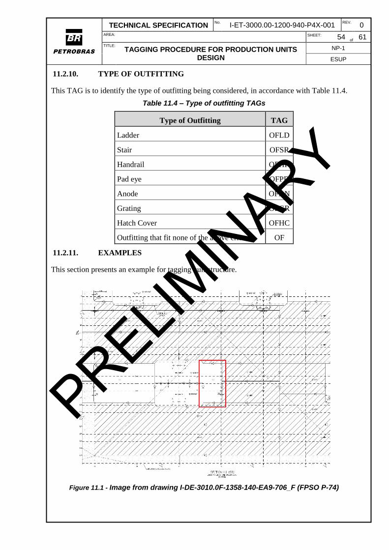
This section aims to guide the construction of TAGs for topside structural elements (i.e. beams,

columns, braces and plates), local coordinate systems and grids planes present in 3D CAE model

Essentially, the definition of TAG for topside’s structural elements is based on their properties,

classification, type and location at platform and indicated through abbreviations as detailed on

section 11.1.2.

Besides that, each type of structure has a different hierarchy on 3D software which also needs an

identification. For linear structural elements such as columns, beams and braces there are the

main hierarchy named “Member System” and the secondary hierarchy “Member part” and shall

be tagged as follows:

LINEAR ELEMENT – MEMBER SYSTEM

TAG: StructureClassification-LocationAtPlatform-SequentialNumber

LINEAR ELEMENT – MEMBER PART

TAG: TypeOfStructure-ProfileSection-SequentialNumber

Example: Primary Beam located at M15 pancake with W610x113 section

Member System – PS-M15-0000001

Member Part – Bm-W610x113-0000001

For surface structural elements, as for example slabs, plates, gratings and coamings, there are

three levels of hierarchy: “Root Plate System, “Leaf Plate System” and “Plate Part”,

respectively. For tagging purposes, are considered only the first two levels and are named as

presented below:

SURFACE ELEMENT – ROOT PLATE SYSTEM

TAG: StructureClassification-LocationAtPlatform-SequentialNumber

SURFACE ELEMENT – LEAF PLATE SYSTEM

TAG: TypeOfStructure-Thickness-SequentialNumber

Example: 8mm deck plate (slab) located at second level of M07

Root Plate System – SS-M07-0000001

Leaf Plate System – Sl-8mm-0000001

If a single outfitting is defined as unique structure, its parts shall be named according to next

rules:

PRELIMIN

ARY

TECHNICAL SPECIFICATION No.

I-ET-3000.00-1200-940-P4X-001 REV.

0 AREA:

SHEET: 49 of

61 TITLE:

TAGGING PROCEDURE FOR PRODUCTION UNITS DESIGN

NP-1

ESUP

OUTFITTING ELEMENT

TAG: StructureClassification-LocationAtPlatform-SequentialNumber

Example: Ladder located at first level of M01

Root Plate System – OFLD-M01-0000001

11.1.1. LOCAL COORDINATE SYSTEM AND GRID PLANES

For local coordinate system related to each process module and other topsides structures, its tag

shall be according to with the next definition:

TAG: LocationAtPlatform-CS

Example: Local coordinate system of M15

TAG - M15-CS

Additionally, there are structural grids that are directly related to a local coordinate system and

are composed by planes defined on three main directions (X – Longitudinal, Y – Transversal and

Z). Therefore, its tags shall identify these planes and be according to its position in relation of

vessel’s global coordinate system.

Consequently, the tagging shall be as follows:

Planes at X-axis (YZ) - LocationAtPlatform-FRXXX

XXX is the vessel’s frame number where the plane is located.

Planes at Y-axis (XZ) - LocationAtPlatform-LYYY

YYY is the vessel’s longitudinal number where the plane is located.

Planes at Z-axis (XY) - LocationAtPlatform-ELAAAAA

AAAAA is the elevation from the vessel’s keel line (in millimeters) where the plane is

located

11.1.2. ABBREVIATION

Finally, the abbreviations for each variable for tag composition shall be according to the

following definitions:

i. Structure Classification – defined by the importance of the element in the

global structural resistance

a. Primary Structure – PS

b. Secondary Structure – SS

c. Outfitting – OF – For general elements defined as surfaces or linear

items

d. Outfitting (Ladder) – OFLD (For unique structure)

e. Outfitting (Stair) – OFSR (For unique structure)

f. Outfitting (Handrail) – OFHR (For unique structure)

ii. Location at Platform

PRELIMIN

ARY

TECHNICAL SPECIFICATION No.

I-ET-3000.00-1200-940-P4X-001 REV.

0 AREA:

SHEET: 50 of

61 TITLE:

TAGGING PROCEDURE FOR PRODUCTION UNITS DESIGN

NP-1

ESUP

a. Module Process – M01 to M18

b. Crane - CR

c. Flare Tower – FT

d. Pipe Rack – PR

e. Riser Pipe Rack – RPR

f. Equipment base – EB

g. Hull – HL

iii. Type of Structure

a. Column – CO

b. Beam – BM

c. Brace – BR

d. Slab – SL

e. Plate – PL

f. Grating – GR

g. Coaming - CO

iv. Thickness (only for surface elements) - Value of the thickness in millimeters

followed by “mm”

v. Profile Section (only for linear elements) – Catalog or usual name for the

structural profile according to ET-3010.00-1400-140-P4X-001 – Catálogo de

Chapas e Perfis Estruturais – Topside

vi. Sequential Number – Defined to distinguish the elements and composed by

seven characters

11.2. HULL STRUCTURAL ELEMENTS

This section aims to guide the construction of TAGs for hull’s structural elements present in 3D

CAE model.

Element localization shall be in accordance with the following rule:

Plates and brackets:

a) Root Plate System

TAG: LocationAtHull-TransversalLocalization-

LongitudinalLocalization-HullSide-HULL-SequentialNumber

b) Surface Element – Leaf Plate System

TAG: TypeOfStructure-Thickness-SequentialNumber

Longitudinals:

Root Plate System

TAG: LocationAtHull-TransversalLocalization-

LongitudinalLocalization-HullSide-HULL-SequentialNumber

PRELIMIN

ARY

TECHNICAL SPECIFICATION No.

I-ET-3000.00-1200-940-P4X-001 REV.

0 AREA:

SHEET: 51 of

61 TITLE:

TAGGING PROCEDURE FOR PRODUCTION UNITS DESIGN

NP-1

ESUP

Root Profile System

TAG: TypeOfStructure-ProfileSection-SectionProperties-

SequentialNumber

Outfitting:

For unique outfitting structure, consider the following tagging rule:

TAG: TypeofOutifitting-LocationAtHull-TransversalLocalization-

LongitudinalLocalization-HullSide-HULL-SequentialNumber

If a single outfitting is not a unique structure, its parts shall be named according to

previous rules.

11.2.1. LOCATION AT HULL

For element location at the hull, refer to Table 11.1.

Table 11.1 - Hull main parts tags

Hull Location TAG

Main Deck MD

Side Shell SSH

Bottom BL

Longitudinal Bulkhead LBH

Transversal Bulkhead TBH

Stringer X STR-X

Frame FR

Marine Pipe Rack MPR

Pull-In PI

Diving Station DVS

Fender Back FEB

Crane Seats CS

Mooring Balconies MB

Fairleads FLD

Upper riser balcony URB

Lower riser balcony LRB

Caisson CAI

Vent Post VP

PRELIMIN

ARY

TECHNICAL SPECIFICATION No.

I-ET-3000.00-1200-940-P4X-001 REV.

0 AREA:

SHEET: 52 of

61 TITLE:

TAGGING PROCEDURE FOR PRODUCTION UNITS DESIGN

NP-1

ESUP

Hull Location TAG

Well stimulation WS

Helideck HLD

Accommodation ACC

Machine Room Deck X MCR-X

Sea Chest SCH

Stool STO

If the structure is made of linear elements, such as marine pipe-rack and pull-in, address to the

adopted TAG representation for Topside structures, considering the field LocationAtPlatform the

TAG presented in Table 11.1, and adding the word “HULL” to the TAG. For example, marine

pipe rack root plate system would be “MPR-StructureClassification-HULL-SequentialNumber”.

If any structure is not listed in Table 11.1, their TAG shall be agreed with Petrobras.

11.2.2. TRANSVERSAL LOCALIZATION

It shall identify the frame where the structure is located. For structures that starts in one frame

and finishes in the next one, it shall be used the number of the starting frame.

If the structure finishes between frames and is not connected to either of them, it shall be used

the frame with smaller sequential.

The tag must contain the following syntax: FRXX, where XX is the frame number.

11.2.3. LONGITUDINAL LOCALIZATION

It shall identify the longitudinal where the structure is located. For structures that starts in one

longitudinal and finishes in the next one, it shall be used the number of the starting longitudinal.

If the structure finishes between longitudinals and is not connected to either of them, it shall be

used the longitudinal with smaller sequential.

The tag must contain the following syntax: LYY, where YY is the longitudinal number.

Longitudinal LYY shall be numbered according to its plate position and in accordance with the

following rule:

Main Deck: ascending order from the center line towards the side shell;

Bottom: same as main deck;

Transversal bulkhead: same as main deck;

Side shell: ascending order from the base line towards the main deck;

Longitudinal bulkhead: same as side shell.

11.2.4. HULL SIDE

It defines in which side of the hull the structure is located.

The tag must contain the following syntaxt: PS for Portside or SS to Starboard.

11.2.5. SEQUENTIAL NUMBER

PRELIMIN

ARY

TECHNICAL SPECIFICATION No.

I-ET-3000.00-1200-940-P4X-001 REV.

0 AREA:

SHEET: 53 of

61 TITLE:

TAGGING PROCEDURE FOR PRODUCTION UNITS DESIGN

NP-1

ESUP

When more than one element with the same characteristics are in the same location, they shall

differ by the sequential number (seven characters long). Order shall be the same as LYY order

presented in section 11.2.3.

11.2.6. TYPE OF STRUCTURE

For the type of structure tag, refer to Table 11.2.

.

Table 11.2 - Structural elements types tags

Structural Elements Types TAG

Plate PL

Bracket BKT

Flange FLG

Double Plate DBP

11.2.7. THICKNESS

This field represents plate thickness. All specified thickness shall be in millimeters (mm).

11.2.8. PROFILE SECTION

This TAG is to identify the profile section type, in accordance with Table 11.3.

Table 11.3 – Profile Sections TAGs

Profile Section TAG

Flat Bar FB

L L

T T

Bulb B

Reinforcements that fit none of the above criteria REF

11.2.9. SECTION PROPERTIES

Section Properties shall be presented in this field, separating length and thickness with a “x”

sign. If there is a flange in the profile, web section comes first, then a “+” sign and then the

flange section. All dimensions shall be in millimeters.

For instance, a flat bar with 100 mm in length and 12 mm thickness, section properties field will

be 100x12. If the section is a “T” composed by a web equal to the previous flat bar and a flange

of a length of 20 mm and 8 mm thickness, this field will be 100x12+20x8.

For bulb profiles, this field shall be the name of the profile being used in the project.

If profile section is REF, Petrobras shall be consulted in the way that this field will be completed.

PRELIMIN

ARY

TECHNICAL SPECIFICATION No.

I-ET-3000.00-1200-940-P4X-001 REV.

0 AREA:

SHEET: 54 of

61 TITLE:

TAGGING PROCEDURE FOR PRODUCTION UNITS DESIGN

NP-1

ESUP

11.2.10. TYPE OF OUTFITTING

This TAG is to identify the type of outfitting being considered, in accordance with Table 11.4.

Table 11.4 – Type of outfitting TAGs

Type of Outfitting TAG

Ladder OFLD

Stair OFSR

Handrail OFHR

Pad eye OFPD

Anode OFAN

Grating OFGR

Hatch Cover OFHC

Outfitting that fit none of the above criteria OF

11.2.11. EXAMPLES

This section presents an example for tagging hull structure.

Figure 11.1 - Image from drawing I-DE-3010.0F-1358-140-EA9-706_F (FPSO P-74)

PRELIMIN

ARY

TECHNICAL SPECIFICATION No.

I-ET-3000.00-1200-940-P4X-001 REV.

0 AREA:

SHEET: 55 of

61 TITLE:

TAGGING PROCEDURE FOR PRODUCTION UNITS DESIGN

NP-1

ESUP

Plate:

Plate highlighted in Erro! Fonte de referência não encontrada. is located at the main

deck, starboard, is located between L4 and L10 and starts in frame 71. Considering this, plate tag

will be:

Root Plate System – MD-FR71-L4-SB-HULL-0000001

Leaf Plate System – PL-31.5mm-0000001

Bracket:

If there is a bracket or stool in this plate, their tag will be:

Root Plate System – MD-FR71-L4-SB-HULL-0000001

Leaf Plate System – BKT-12mm-0000001

Longitudinal:

Considering the longitudinal number 45 in the portside longitudinal bulkhead, starting in

frame 71, a “T” profile and section”400x20+150x15”. It tag will be:

Root Plate System – LBH-F71-L45-PS-HULL-0000001

Root Profile System – LG-T-400x20+150x15-0000001

Outfitting:

Considering the anode located in the bottom longitudinal number 3 (portside), between

frames 98 and 99. It tag will be:

OFAN-BL-FR98-L3-PS-HULL-0000001

PRELIMIN

ARY

TECHNICAL SPECIFICATION No.

I-ET-3000.00-1200-940-P4X-001 REV.

0 AREA:

SHEET: 56 of

61 TITLE:

TAGGING PROCEDURE FOR PRODUCTION UNITS DESIGN

NP-1

ESUP

12. MARINE SYSTEMS

Identification TAGs of Marine System equipment shall be defined according to PETROBRAS

standards NI-1521 - Identification of Industrial Equipment and considering alternative of Annex

C of NI-1710 - Coding of Technical Engineering Documents for the area.

This Standard establishes the conditions required for the identification of equipment belonging to

industrial facilities of PETROBRAS.

This Standard does not apply to measurement and control instruments nor to piping items. For

these items, refer to Automation and Piping sections.

In all documents pertaining to an industrial equipment or in documents where reference is made

to an industrial equipment, the industrial equipment shall be identified according to NI-1521.

PRELIMIN

ARY

TECHNICAL SPECIFICATION No.

I-ET-3000.00-1200-940-P4X-001 REV.

0 AREA:

SHEET: 57 of

61 TITLE:

TAGGING PROCEDURE FOR PRODUCTION UNITS DESIGN

NP-1

ESUP

13. TELECOMUNICATION

Identification TAGs of Telecom equipment shall be defined according to PETROBRAS

standards NI-1521 - Identification of Industrial Equipment and considering alternative of Annex

C of NI-1710 - Coding of Technical Engineering Documents for the area.

This Standard establishes the conditions required for the identification of equipment belonging to

industrial facilities of PETROBRAS.

This Standard does not apply to measurement and control instruments nor to piping items. For

these items, refer to Automation and Piping sections.

In all documents pertaining to an industrial equipment or in documents where reference is made

to an industrial equipment, the industrial equipment shall be identified according to NI-1521.

PRELIMIN

ARY

TECHNICAL SPECIFICATION No.

I-ET-3000.00-1200-940-P4X-001 REV.

0 AREA:

SHEET: 58 of

61 TITLE:

TAGGING PROCEDURE FOR PRODUCTION UNITS DESIGN

NP-1

ESUP

14. 3D MODEL (ALL DISCIPLINES)

For volumes on 3D model, tagging shall be as the following procedure:

(A)(-)(B)(-)(C)

Where:

(A) = Abbreviation, according to Table 14.1.

(-) = hyphen

(B) = sequential code (three numbers)

(-) = hyphen

(C) = Volume purpose. If this volume is related to a specific object, C must be equal to its tag. If

it is not related to a specific object, C must be equal to the function and the area (separated by

hyphen “-“). The function shall be selected from X and the area must be selected from Y.

Table 14.1 - Abbreviations for volumes.

Volume characteristic Abbreviation

Regions that must be

interference free

VOL

Physical spaces limits LIM

Optional volumes that

might be used for

automatic drawings

generation

DRAW

Table 14.2 Abbreviations for functions.

Functions Abbreviation

ESCRT Escape route

HLDKOP Helideck obstacle

free setor

CBLTRY Cable tray

OPER Operation

MAINT Maintenance

FUT Future

CGHDL Cargo handling

CLAREA Classified area

ROOM Closed room

DETEC Flame detectors

range

PRELIMIN

ARY

TECHNICAL SPECIFICATION No.

I-ET-3000.00-1200-940-P4X-001 REV.

0 AREA:

SHEET: 59 of

61 TITLE:

TAGGING PROCEDURE FOR PRODUCTION UNITS DESIGN

NP-1

ESUP

SPRK Sprinklers

DOOR Door opening

BOUND Limit

DRGHT Draught

PPAR Piping area

PCKG Package

Table 14.3 Abbreviations for areas.

Areas Abbreviation

ACCM ACCOMODATION

AFTEXT AFT EXTENSION

BOATSW BOATSWAIN STORE

CSSN CAISSON

DVST{1 digit number} DIVING STATIONS

ENGR ENGINE ROOM

FLLST FILLING STATION

FLRFN FLARE FOUNDATION

FNDR FENDER

FRCST FORECASTLE

FREXT FORE EXTENSION

FRLD FAIRLEAD

HULL HULL

HDPP HARD PIPE

HLDK HELIDECK

LAYDWN{1 digit number} LAY DOWN AREAS

LFBTPL LIFEBOAT PLATFORM

MDK MAIN DECK

MPPRK MARINE PIPERACK

MRGBCN MOORING BALCONY

OFFL OFFLOADING

PLLIN PULL IN

PPDK POOP DECK

PRELIMIN

ARY

TECHNICAL SPECIFICATION No.

I-ET-3000.00-1200-940-P4X-001 REV.

0 AREA:

SHEET: 60 of

61 TITLE:

TAGGING PROCEDURE FOR PRODUCTION UNITS DESIGN

NP-1

ESUP

PRLBD PARALLEL BODY

PUMPR PUMP ROOM

STEEGR STEERING GEAR ROOM

TEMP TEMPORARY OBJECTS

TKACC STRUCTURAL TANKS ACCESS

TWGST TOWING STATION

UPRB UPPER RISER BALCONY

LWRB LOWER RISER BALCONY

RSPPRK RISER PIPERACK

VNTPT VENT POST

WSTM WELL STIMULATION SUPPORT

LAB LABORATORY

FLR FLARE

M{2 digits number plus letter} TOPSIDE MODULES

Examples:

a) First volume reserved to panel PN-1220001 future expansion (future indication would be

stored within an attribute): VOL-001-PN-1220001

VOL: Regions that must be interference free

001: Sequential Numbering

PN-1220001: Related object tag

b) Second volume reserved to pump B-1221001A operation (operation indication would be

stored within an attribute): VOL-002-B-1221001A

VOL: Regions that must be interference free

002: Sequential Numbering

B-1221001A: Related object tag

c) First volume reserved to pump B-1221001A maintenance (maintenance indication would

be stored within an attribute): VOL-001-B-1221001A

VOL: Regions that must be interference free

001: Sequential Numbering

B-1221001A: Related object tag

PRELIMIN

ARY

TECHNICAL SPECIFICATION No.

I-ET-3000.00-1200-940-P4X-001 REV.

0 AREA:

SHEET: 61 of

61 TITLE:

TAGGING PROCEDURE FOR PRODUCTION UNITS DESIGN

NP-1

ESUP

d) First volume reserved to cargo handling in module 1: VOL-001-CGHDL-M01

VOL: Regions that must be interference free

001: Sequential Numbering

CGHDL-M01: cargo handling in module 1

e) First volume reserved to escape route in module 1: VOL-001-ESCRT-M01

VOL: Regions that must be interference free

001: Sequential Numbering

ESCRT-M01: escape route in module 1

f) First volume reserved to classified area in module 1: LIM-001-CLAREA-M01

LIM: Physical spaces limits

001: Sequential Numbering

CLAREA-M01: classified area in module 1

PRELIMIN

ARY


Recommended