TECHNICAL SPECIFICATION N°. I-ET-3010.1M-1234-560-P4X-001 CLIENT: SRGE SHEET: 1 of 24 JOB: REFERENCE BASIC DESIGN 1001056398 0010 AREA: BÚZIOS DP&T-SRGE TITLE: AMINE REGENERATION PACKAGE NP-1 ESUP MICROSOFT WORD / V.2010 / I-ET-3010.1M-1234-560-P4X-001_0.DOCX INDEX OF REVISIONS REV. DESCRIPTION AND/OR REVISED SHEETS 0 ORIGINAL ISSUE REV. 0 REV. A REV. B REV. C REV. D REV. E REV. F REV. G REV. H DATE APR/05/19 DESIGN ESUP EXECUTION ESTEVES CHECK PONTE APPROVAL TMCAMPOS INFORMATION IN THIS DOCUMENT IS PROPERTY OF PETROBRAS, BEING PROHIBITED OUTSIDE OF THEIR PURPOSE. FORM OWNED TO PETROBRAS N-0381 REV.L. PRELIMINARY
This Technical Specification covers the minimum requirements for design, engineering, materials, fabrication, inspection, testing, commissioning and pre-commissioning of the AMINE REGENERATION PACKAGE (Z-1234001) to be supplied for REFERENCE BASIC DESIGN.
The AMINE REGENERATION PACKAGE (Z-1234001) shall be provided with all necessary instruments to operate safely, adequately and without interruption in an offshore facility.
2 NORMATIVE REFERENCES AND DESIGN SPECIFICATIONS
2.1 CLASSIFICATION
PACKAGER/ MANUFACTURER shall perform the work in accordance with the requirements of the Classification Society.
PACKAGER/ MANUFACTURER is responsibility to submit to the Classification Society the documentation in compliance with stated Rules.
2.2 CODES AND STANDARDS
The latest editions of the following codes and standards shall be used as design guidelines:
AISC ASD - Steel Construction Manual
API 610 - Centrifugal Pumps for Petroleum, Chemical, and Gas Industry Services
API 614 - Lubrication, Shaft-sealing and Control-oil Systems and Auxiliaries for Petroleum, Chemical and Gas Industry Services
API 660 - Shell and Tube Heat Exchangers for General Refinery Services
API 662 - Plate Heat Exchangers for General Refinery Services
API 670 - Machinery Protection Systems (Vibration, Axial Position and Bearing Temperature Monitoring)
API 674 - Positive Displacement Pumps-Reciprocating
API RP14C - Recommended Practice for Analysis, Design, Installation and Testing of Basic Surface Safety Systems for Offshore Production Platforms
API RP 14E - Recommended Practice for Design and Installation of Offshore Production Platform Piping Systems
API RP 14J - Recommended practice for design and Hazard Analysis for Offshore Production Facilities
API RP 14FZ - Recommended Practice for Design and Installation Of Electrical Systems For Fixed And Floating Offshore Petroleum Facilities For Unclassified And Class 1, Zone 0,1 And 2 Locations
API RP 505 - Classification of locations for Electrical Installations at Petroleum Facilities Classified as Class 1, Zone 0, Zone 1 and Zone 2
API RP 520 - Sizing, Selection and Installation of Pressure Relieving Devices in Refineries Part 1&2
API RP 521 - Guide for Pressure Relieving and Depressuring Systems
ASME B16.5 - Pipe Flanges and Flanged Fittings
ASME B 31.3 - Process Piping
ASME BPVC X - GRP Vessels
ASME BPVC V - Boiler and Pressure Vessel Code. Non-Destructive Examination;
ASME BPVC VIII - Div.1 and Dv 2 Boiler and Pressure Vessel Code. Rules for construction of pressure vessels
ASME BPVC IX - Boiler and Pressure Vessel Code. Welding and Brazing Qualifications
AWS D1.1 - Structural Welding Code – Steel
IEC 61892-6 - Mobile and fixed offshore units – Electrical installations – Installation
IEC 61892-7 - Mobile and fixed offshore units – Electrical installations – Hazardous areas
IEC 61260 - Electroacoustics-Octave Band and Fractional-Octave-Band Filters
ISA - Handbook of Control Valves, Chapter 7 - Control Valve Noise, Part 2 - Universal Valve Noise Prediction Method
2.3 GOVERNMENTAL REGULATION
NR 10 - Segurança em Instalações e Serviços em Eletricidade (Brazilian Labor Ministry Rules)
NR 13 - Caldeiras, Vasos de Pressão, Tubulações e Tanques Metálicos de Armazenamento (Brazilian Labor Ministry Rules)
NR 26 - Sinalização de Segurança (Brazilian Labor Ministry Rules)
NR 37 - Saúde e Segurança em Plataformas de Petróleo (Brazilian Labor Ministry Rules)
IBAMA - Brazilian IBAMA environmental regulations concerning the discharge of all types of effluents
INMETRO - INMETRO Resolution 179, May 18th 2010 and their annexes
Governmental codes, regulations, ordinances or rules applicable to the equipment in Brazil shall prevail over the requirements of above specifications, including reference codes and standards and/ or these engineering specifications, only in those cases where they are more stringent.
I-RL-3010.1M-1200-940-P4X-001 - GENERAL SPECIFICATIONS FOR AVAILABLE
UTILITIES
I-RL-3010.1M-1350-960-P4X-009 - MOTION ANALYSIS
2.5 CONFLICTING REQUIREMENTS
In case of conflicting requirements between this technical specification and other cited references, the most stringent shall prevail. If necessary the PACKAGER/ MANUFACTURER may revert to PETROBRAS for clarification.
3 DEFINITIONS AND ABBREVIATIONS
3.1 DEFINITIONS
3.1.1 PACKAGER: Company responsible for the project, assembly, construction, fabrication, test and furnishing of the Package.
3.1.2 MANUFACTURER: The supplier, vendor or Contractor. Company responsible for the fabrication of equipment or components internal to the Package.
3.1.3 Package Unit or Package: An assembly of equipment supplied interconnected, tested and operating, requiring only the available utilities from the FPSO for full operation.
3.2 ABBREVIATIONS
CRA - Corrosion Resistant Alloys
CSS - Control and Safety System
Class - Classification Society
FAT - Factory Acceptance Test
FPSO - Floating Production Storage and Offloading
HAZOP - Hazard and Operability Study
SS - Stainless Steel
4 GENERAL FUNCTIONAL REQUIREMENTS
4.1 OPERATION ENVIRONMENT
4.1.1 The equipment supplied shall be suitable for the environment and range of ambient condition including, atmospheric pressure, relative humidity, rainfall, air temperature (dry-bulb) (see Obs.1), characteristic monthly values and wind motions defined in revision D of I-ET-3A26.00-1000-941-PPC-001 – METOCEAN DATA.
4.2.1 The necessary design data and information on motion requirements are given in I-RL-3010.1M-1350-960-P4X-009 - MOTION ANALYSIS
4.3 PACKAGE LOCATION AND AREA CLASSIFICATION
4.3.1 The Amine Regeneration Package shall be installed on module M-08 as informed in I-DE-3010.1M-1200-942-P4X-002 - GENERAL ARRANGEMENT. For available space also see I-DE-3010.1M-1418-942-P4X-001 M-08 – H2S REMOVAL SYSTEM - EQUIPMENT LAYOUT PLAN.
4.3.2 For area classification see I-DE-3010.1M-5400-94A-P4X-001 – AREA CLASSIFICATION – GENERAL
4.4 DESIGN LOADS
4.4.1 In addition to the Code described loads and loads due to vessel motion described in I-RL-3010.1M-1350-960-P4X-009 – MOTION ANALYSIS, the following design loads must be considered where relevant:
4.5.1 PACKAGER/ MANUFACTURER shall design and fabricate the complete package’s equipment for a minimum lifetime of 25 years.
4.6 NOISE
4.6.1 Noise control analysis is a mandatory item to be carried out, according to I-ET-3010.1M-1200-300-P4X-001 - NOISE CONTROL REQUIREMENTS FOR TOPSIDE.
4.7 CORROSION MONITORING
4.7.1 PACKAGER/ MANUFACTURER shall verify the need for corrosion monitoring within the package and submit verification to PETROBRAS for approval. Refer to I-ET-3010.1M-1200-940-P4X-002 – CORROSION MONITORING SYSTEM.
5 PACKAGE SPECIFICATION
PURCHASER shall select a PACKAGER/MANUFACTURER considering a proven experience supplying this type of equipment/technology. PURCHASER shall submit the name of the PACKAGER/MANUFACTURER to PETROBRAS approval.
5.1 SCOPE OF SUPPLY
5.1.1 The AMINE REGENERATION PACKAGE shall be complete in all respect and the scope of supply shall include but not be limited to the major equipment described in the document I-FD-3010.1M-1234-560-P4X-001 - AMINE REGENERATION PACKAGE - M-08 and shown in Table 1.
Lean Amine Booster Pump B-Z-1234001-01A/B (2 x 100%)
Lean Amine Circulation Pump B-Z-1234001-02A/B (2 x 100%)
Amine Stripper Reflux Pump B-Z-1234001-03A/B (2 x 100%)
Anti-Foam Injection Pump B-Z-1234001-04 (1 x 100%)
Amine Make Up Pump B-Z-1234001-05 (1 x 100%)
Lean Amine Cartridge Filter FT-Z-1234001-01A/B (2 x 100%)
Lean Amine Carbon Filter FT-Z-1234001-02 (1 x 100%)
Secondary Lean Amine Cartridge Filter FT-Z-1234001-03 (1 x 100%)
Lean/Rich Amine Exchanger P-Z-1234001-01A/B (2 x 100%)
Lean Amine Cooler P-Z-1234001-02A/B (2 x 50%)
Amine Stripper Overhead Condenser P-Z-1234001-03 (1 x 100%)
Amine Stripper Reboiler P-Z-1234001-04A/B (2 x 50%)
Amine Stripper T-Z-1234001 (1 x 100%)
Rich Amine Flash Drum V-Z-1234001-01 (1 x 100%)
Amine Surge Drum V-Z-1234001-02 (1 x 100%)
Amine Sump Drum V-Z-1234001-03 (1 x 100%)
Amine Stripper Reflux Drum V-Z-1234001-04 (1 x 100%)
Anti-Foam Injection Tank TQ-Z-1234001-01 (1 x 100%)
Amine Make-Up Tank TQ-Z-1234001-02 (1 x 100%)
5.2 PROCESS DESIGN
5.2.1 PACKAGER/ MANUFACTURER shall design and sizing the package’s equipment for the full range of process conditions as specified in the Process Data Sheet I-FD-3010.1M-1234-560-P4X-001 - AMINE REGENERATION PACKAGE - M-08 and in accordance with the following process diagrams:
a) I-DE-3010.1M-1234-944-P4X-001 - INLET GAS K.O. DRUM AND SOUR GAS FILTERS;
b) I-DE-3010.1M-1234-944-P4X-002 - AMINE CONTACTOR “A”;
c) I-DE-3010.1M-1234-944-P4X-003 AMINE CONTACTOR “B”;
a) Definition of number, size and location of all process and instrument related nozzles of AMINE REGENERATION PACKAGE (Z-1234001) battery limits (refer to the I-DE-3010.1M-1234-944-P4X-004 - AMINE REGENERATION PACKAGE);
b) Design and definition of all vessel internals and their appropriate locations; c) Design and definition of internal support requirements for installing the internals in the
vessels.
5.2.3 The Amine Regeneration Package shall exhibit stable operation and shall meet the H2S specification while treating inlet gas at flow rates between 10 and 100 percent of the nominal design capacity of the system.
5.2.4 A solvent handling system shall be incorporated, comprising the following:
a) A drain header shall gather any drains from the system. The drain system shall be a completely closed system to avoid H2S to atmosphere or O2 ingress into the system.
b) The drain header should be flushed with wash water after drainage. For this purpose utility connections are provided at the dead ends when the line is leaking.
c) The drain header through the package to be self draining to a drain vessel to avoid soil contamination when the line is leaking.
5.2.5 All drains from equipment and instruments shall be piped to the appropriate drain system via common header pipe terminated with flanged connection. One common drain connection shall be provided for each drain system (hazardous and non-hazardous). Similarly all vent connections shall be combined into a single flare/vent line terminated with a flanged connection at skid edge. Flare/vent line shall have no pockets and shall be free draining towards flare.
5.2.6 Internal baffles shall be installed to restrict liquid movement due to ship motion. For liquid supply to the stripping gas column, provisions shall be made to avoid alternate starving and flooding of the column caused by the same motion.
5.2.7 All relief valves shall be self-draining to the process equipment. The relief valve assemblies shall include block valves with interlocking devices. The valves shall be operable at top of platform.
5.2.8 Vents and drains on heat exchanger may not be required if venting and draining can be done via other equipment. If vent and drain is provided on heat exchangers, they shall have a valve and a blind flange.
5.2.9 There shall be continuous fall in the drain lines toward the terminal point. If required high and low pressure drains shall be routed separately.
5.2.10 Issues to be addressed by PACKAGER/ MANUFACTURER:
a) Required chemical injection points, taking contingency into consideration; b) Allowable backpressure on Amine Stripper Reflux Drum connection to the vent.
5.3 MECHANICAL AND PIPING
5.3.1 Each pump shall be provided with discharge check-valve and suction and discharge isolation valves, plus all necessary controls and adequate drainage piping and valve facilities.
5.3.2 For pressures above 20 bar g, double block and bleed isolation valves are required.
5.3.3 Vessels shall be built with removable internals suitable sized in sections, to pass through man hole.
5.3.4 Heat exchanger piping shall not be supported on the shell and shall not hamper the removal of the tube bundle and shell/ channel cover. A removable pipe spool may be required.
5.3.5 Piping at pumps shall be sufficiently flexible and adequately supported to prevent the equipment nozzle from being subjected to any stress that could disturb the alignment and internal clearance.
5.3.6 PACKAGER shall prepare detailed assembly, disassembly and maintenance procedures, describing the use of all involved handling devices and including all required preventive and corrective maintenance tasks. PACKAGER shall inform the
need for disassembling any component or equipment in order to facilitate access for maintenance. Suitable maintenance routes shall be provided to remove the main components and auxiliaries, avoiding interference with structures, piping, cabling, electric conduits and supports, equipment etc. This plan shall be submitted to PETROBRAS for approval.
5.3.7 All skid piping within the limits of supply shall be fabricated and terminated at the baseplate edge by means of valves and/ or flanges and blind flanges according to ASME B16.5.
5.3.8 The flanges shall be flush with the transverse ends of the skid having a uniform B.O.P. (Bottom of Pipe) at as low as practical elevation. This shall be shown on PACKAGER/MANUFACTURER’s P&ID’s and General Arrangement drawings. All tubing for the off-skid interfaces shall be terminated at the skid by means of compression fitting valves.
5.3.9 All piping shall be rigidly supported for service and shipment; supports on the module plates shall not be accepted without under deck stiffening. The supporting and installation shall enable piping removal without disturbing structural members.
5.3.10 All drain lines shall be routed through the deck to a common drain header, terminated in one flange at the skid edge for connection to PETROBRAS overboard drain system.
5.3.11 There shall be a continuous fall, with no low point traps along the drain lines toward the end point. Drain line connections into the drain header shall be entering from the top.
5.3.12 All drain lines shall be hard-piped and provided with means to prevent vacuum conditions in the line.
5.3.13 Socket welding is only permitted for piping sizes equal or less than 1½ inch until pressure class 1500#. All piping above 1 ½ inch shall be butt-welded.
5.3.14 All valves shall be positioned with the stem pointing upwards. They shall be located in such a way that the handwheel or actuator will not obstruct walkways and be easily accessible for operation and maintenance. Where hand operated valves are not easily operable, gear operated valves shall be used.
5.3.15 Valves, instruments etc. elevated above 1.75 m above the module base plate shall have access ladders or platform provided.
5.3.16 The level gauges shall be installed in such position that the level indicated in receiver will be easily seen. All level gauges shall have flanged connections, which can be isolated, and be complete with vent and drain, valves and connection.
5.3.17 Sampling point / facilities shall be provided complete with necessary fittings and valves, and the design should reflect nature of the fluids being sampled.
5.3.18 Utility hose stations shall be installed throughout the package on strategic places for maintenance and cleaning purposes.
5.3.19 The manifolds shall be located such that all points of use in area can be covered by using 15 m long hoses.
5.3.20 The design and assembly of all metallic process piping shall be according ASME B31.3 code.
5.3.21 All process, utility and drainage piping, pipe supports and valves shall be provided;
5.3.22 Piping shall be routed to allow access for maintenance. Removal of replacement of equipment shall be possible with a minimum dismantling of piping.
5.3.23 Piping systems shall not extend the operating floor.
5.3.24 All structural steel work including main structural skid, support frames, supports for equipment, ladders, walkways, platforms, grating and drip trays shall be provided.
5.3.25 All other miscellaneous items and equipment which are required for the service and proper operation of the Amine Regeneration Package shall be included.
5.3.26 Equipment and piping subjected to temperature of 60ºC and above shall receive a personal protection system, by means of 316SS wire mesh / perforated plates. Alternatively, a thermally insulated may be applied. Equipment and piping in which heat conservation is necessary shall be thermal insulated. The thermal insulation shall be according latest revision of I-ET-3010.00-1200-431-P4X-501 – THERMAL INSULATION FOR MARITME INSTALLATIONS
5.3.27 Studs, bolts, tightening bolts and nuts shall be according I-ET-3010.00-1200-251-P4X-001 – BOLT MATERIALS
5.4 MATERIALS
5.4.1 The PAKAGER is responsible for the materials specifications in accordance with process fluid and operational conditions. For materials selection, the inlet fluids characteristics shall be considered as following:
a) Rich Amine CO2 content: up to 4,48% mol;
b) Rich Amine H2S content: up to 514 ppmv;
5.4.2 Considering the high H2S and CO2 content , all equipment and lines in contant with rich or lean amine shall be as a mimimun 316L as a clad or intergral material. Other CRA materials, with better corrosion resistance, may be specificed by PAKAGER.
5.4.3 The corrosion allowance (CA) shall be defined using API RP 581 methodology.
5.4.4 All materials shall comply with ISO 15156 and API RP 945.
5.4.5 In all cases, PACKAGER/MANUFACTURER shall submit the detailed material list, including all equipment and their components, for PETROBRAS approval prior manufacture activities.
5.5 DESIGN AND FABRICATION
5.5.1 Heat Exchanger
a) Shell and tube heat exchangers shall comply with the requirements of NR 13 (Brazilian Labor Ministry Safety Rules) and I-ET-3010.1M-1200-451-P4X-001 – SHELL & TUBE HEAT EXCHANGER SPECIFICATION.
b) Plate and Frame heat exchangers shall comply with the requirements I-ET-3010.1M-1200-456-P4X-001 – PLATE HEAT EXCHANGER SPECIFICATION.
c) The heat exchanger types are defined at Datasheet I-FD-3010.1M-1234-560-P4X-001 - AMINE REGENERATION PACKAGE - M-08
a) Pumps shall comply with the requirements I-ET-3010.1M-1200-310-P4X-001 – CENTRIFUGAL PUMPS SPECIFICATION and I-ET-3010.1M-1200-310-P4X-002 - POSITIVE DISPLACEMENT PUMPS SPECIFICATION FOR TOPSIDE.
b) For centrifugal pump type, center line mounted with induction electric motor, instruments, coupling and guard (non-sparking) mounted on common base plate in compliance with API 610 Standard.
c) Reciprocating pumps may be used instead of centrifugal pumps for Lean Amine Circulation Service if recommended by the PACKAGER/ MANUFACTURER, in compliance with API 674 Standard.
d) The pump types are defined at Datasheet I-FD-3010.1M-1234-560-P4X-001 - AMINE REGENERATION PACKAGE - M-08
e) Pumps shall be provided with guard and shall be of sufficient rigid construction and weather proof.
f) Pump shall have flanged vent and drain nozzles.
g) In order to meet safety regulations, a single mechanical seal with a back-up seal with nitrogen purge, or a double mechanical seals with an external sealing medium shall be specified for pumps.
h) If a leakage of gas to atmosphere could endanger personnel due to toxicity, the pump shall be provided with a barrier system.
5.5.3 Metallic Tanks
a) All Tanks design shall comply with the requirements described in I-ET-3010.00-1200-510-P4X-001 – METALLIC TANKS DESIGN FOR TOPSIDE
5.5.4 Pressure Vessel Design
a) All pressure vessels, columns and filters shall comply with the requirements of NR 13 (Brazilian Labor Ministry Safety Rules) and I-ET-3010.00-1200-540-P4X-001 – REQUIREMENTS FOR PRESSURE VESSELS DESIGN.
5.5.5 Pressure Vessels Fabrication
a) All pressure vessels, columns and filters shall comply with the requirements of I-ET-3010.00-1200-540-P4X-002 – REQUIREMENTS FOR PRESSURE VESSELS FABRICATION.
5.5.6 Welding
a) All equipment, structures and piping welds shall be according the requirements described in the latest revision of I-ET-3010.00-1200-955-P4X-001 – WELDING.
b) Welding must be done following the requirements of API RP 582 - Welding Guidelines for the Chemical, Oil, and Gas Industries and API RP945 - Avoiding Environmental Cracking in Amine Units.
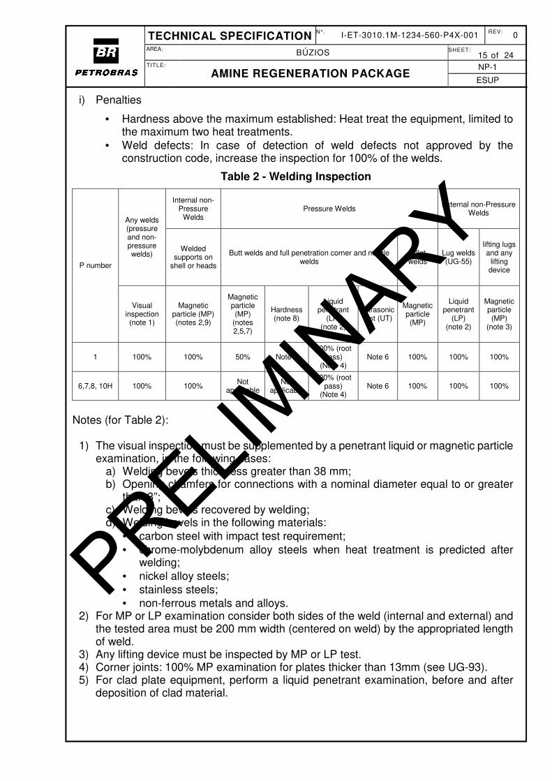
c) The weld hardness of carbon steel equipment, including piping, should not exceed a Brinell hardness of 200.
d) Postweld heat treatment is mandatory for non cladded carbon steel equipments and must follow the requirements of API RP945 - Avoiding Environmental Cracking in Amine Units.
a) Welding inspection and NDEs shall be according the requirements described in the latest revision of I-ET-3010.00-1200-955-P4X-002 – REQUIREMENTS FOR WELDING INSPECTION.
b) For radiography examination the CONTRACTOR must follow ASME Section VIII, part UW (Requirements for Pressure Vessels Fabricated by Welding), with the exceptions and addenda below.
c) The Degree of Radiographic Examination (table UW-12): 100% Radiography (FULL).
d) Besides those joints shown in TABLE UW-12, any case of pressure weld which fulfill the requirements below must be radiographic tested:
• Full penetration tee or corner-type joints including nozzle attachment welds shall be 100% nondestructively tested by either radiographic or ultrasonic examination.
• Welds of any parts, regardless of the material, thickness or service, shall be fully (100 %) radiographed before any severe deformation (thickness to local radius ratio greater than 5 %), by any process, such as spinning, pressing and rolling.
• Welds used for closing guide-holes at the center of formed heads shall be fully (100%) radiographed.
• Shell welds hidden by reinforcement plates shall be ground, examined by magnetic particles or liquid penetrant and be fully (100%) radiographed.
e) For other NDT test, CONTRACTOR must follow ASME Section VIII, part UG (Inspection and Tests), with the addenda below:
f) Visual examination (UG-97): All welds must be subjected to a visual inspection, internal and externally.
g) Magnetic particle and liquid penetrate examination (UG-103):
• Welds: See Table 2 for detailed requirements. • Temporary welds: Temporary welds shall be removed and the metal surface shall
be restored to a smooth contour. The area shall be inspected by magnetic particle or liquid penetrant test for the detection and elimination of defects (note: use the same criteria for full penetration welds).
h) Positive materials identification: required as indicated below:
• The PMI shall be carried out with equipment capable to identify the specified type of material in accordance with established procedure. The equipment shall not make burn marks to the pipe material.
• The PMI shall be done prior the welding to identify the materials which will be welded.
• Positive materials identification must be done on: - All stainless steel and chrome- molybdenum steel pipes up to (and
including) 2”, - All stainless steel and chrome-molybdenum steel fittings up to (and
including) 2”, - Any nickel steel or nickel alloy material, - Any internal welded support rings, lugs or other internal permanent
attachment to a stainless steels or Nickel alloy pressure vessel. • If any non-conformance in material type is reported, the extent shall be increased
pipes and fittings higher than 2” to ensure that all mix of material is discovered.
2) For MP or LP examination consider both sides of the weld (internal and external) and the tested area must be 200 mm width (centered on weld) by the appropriated length of weld.
3) Any lifting device must be inspected by MP or LP test. 4) Corner joints: 100% MP examination for plates thicker than 13mm (see UG-93). 5) For clad plate equipment, perform a liquid penetrant examination, before and after
6) Nozzles having a nominal diameter equal to or larger than 4” and self-reinforced nozzles with the opening in the shell having a diameter equal to or greater than 100 mm shall undergo ultrasonic inspection at the following welded joints:
a) full penetration welded joint between nozzle neck and vessel shell; b) welded joint between nozzle neck and reinforcement plate (if any).
7) For nozzles having reinforcement plate, a liquid penetrant or magnetic particle test shall be carried out after the completion of the nozzle-to-neck weld, before the installation of the reinforcement plate.
8) Hardness limits criteria according qualified welding procedure. 9) For all welds of internals to claded shells or heads must be liquid penetrant tested.
5.6 SAFETY REQUIREMENTS
5.6.1 Maximum allowable pressure drop for pressure relief devices shall comply with API requirements.
5.6.2 Piping supports, instrument tappings, design pressures etc. shall be suitable for sustained operation under the pressure pulsations that occur if the bladders of pulsation dampeners fail.
5.6.3 For area classification see I-DE-3010.1M-5400-94A-P4X-001 – AREA CLASSIFICATION – GENERAL.
5.6.4 Mandatory safety items as established in DR-ENGP-M-1.3 - SAFETY ENGINEERING, are to be considered complementary requirements, to the pertinent extent. In case of items in conflict with this document, PURCHASER shall be consulted.
5.6.5 HAZOP and PHA shall be performed according to DR-ENGP-M-1.3 - SAFETY ENGINEERING.
5.6.6 Double block & bleed arrangements are required for isolation of equipment in piping classes of 300# and above.
5.6.7 All safety signs and notices shall be in Portuguese language.
5.7 INSTRUMENTATION
5.7.1 All instrumentation equipment and interface with FPSO automation and control design shall comply with I-ET-3010.00-1200-800-P4X-002 - AUTOMATION, CONTROL AND INSTRUMENTATION ON PACKAGE UNITS.
5.7.2 For package automation type classification see I-ET-3010.1M-1200-800-P4X-014 – AUTOMATION INTERFACE ON PACKAGE UNITS.
5.7.3 All local instruments control valves, control, monitoring and safety protection instruments and devices for remote indication, control, alarms, protection and shut down etc. shall be included.
5.7.4 Automatic temperature control facilities shall be provided for the control of cooling medium flow.
5.7.5 Sampling point / facilities shall be provided complete with necessary fittings and valves for taking glycol samples.
5.8.1 Low-voltage motors inside the package shall comply with latest revision of I-ET-3010.00-5140-712-P4X-001 – LOW-VOLTAGE INDUCTION MOTORS FOR OFFSHORE UNITS.
5.8.2 All electrical equipment and material shall fully comply with the document I-ET-3010.00-5140-700-P4X-002 - SPECIFICATION FOR ELECTRICAL MATERIAL AND EQUIPMENT FOR OFFSHORE UNITS.
5.8.3 Power lighting and grounding installations inside the package shall comply with requirements of I-ET-3010.00-5140-700-P4X-003 – ELECTRICAL REQUIREMENTS FOR PACKAGES FOR OFFSHORE UNITS.
5.8.4 Two diagonally opposite earthing bosses shall be provided on each equipment item, which shall then be connected to the module during construction and assembly phase.
5.9 INSTALLATION REQUIREMENTS
5.9.1 SKID DETAILS
5.9.1.1 This section is only applicable for equipment that is built on a skid.
5.9.1.2 The skid shall be designed to accommodate the entire equipment within the scope of supply. The skid shall be of rigid construction, which will not distort during hoisting, operation and shipment and shall withstand all moments and forces due to the vessel motion.
5.9.1.3 All equipment shall be installed by PACKAGER/MANUFACTURER over structural steel deck plate in position shown in I-DE-3010.1M-1418-942-P4X-001 M-08 – H2S REMOVAL SYSTEM - EQUIPMENT LAYOUT PLAN.
5.9.1.4 All piping terminations shall be flanged.
5.9.1.5 Equipment shall be arranged to allow safe and good personnel access for all operations and maintenance
5.9.1.6 Lifting facilities shall enable lifting of the equipment with crane as a single point lift for transportation and installation. The design and manufacture of the lifting lugs shall be certified. The arrangement of equipment, piping and superstructure shall be such that the centre of gravity coincides approximately with the geometrical centre of the skid. When lifting the skids, complete with all equipment mounted, beam deflection shall not exceed 1/400 L.
5.9.1.7 The skid shall resist all sling forces, including both horizontal and vertical components of the applied sling angle (sling angles shall be within between 50 and 90º with the horizontal plane).
5.9.1.8 Lifting beams, spreader bars, slings, shackles etc. are within PACKAGER/ MANUFACTURER’s scope of supply.
5.9.1.9 Drip trays with drain connections shall be provided underneath equipment where significant spillage is likely to occur.
5.9.1.10 The skid shall be welded to the supporting structures. Skid floor shall be made of plate material with a raised on-slip tread. Welds underneath skid beams shall be ground flush. Skid shall have 2 diagonally opposed earthing bosses.
5.9.1.11 Welding shall be carried out with procedures and operators qualified in accordance with ASME section IX. Welding shall not be performed before qualified welding procedure etc. is approved. Intermittent fillet welds are not permitted.
5.9.2 MAINTENANCE LIFTING BEAMS
5.9.2.1 All required maintenance lifting beams, complete with the necessary hoisting and lifting gear, shall be provided to facilitate safe and easy maintenance.
5.9.2.2 All lifting beams shall overhang by at least 1.2 m into agreed lay-down areas.
5.9.2.3 The deflection of the maintenance crane/ hoisting beams shall not exceed 1/500 of the span length.
5.9.2.4 All beams and lifting gear shall be subject to load testing, witnessed by PETROBRAS representative and classification society.
5.10 PAINTING
5.10.1 Painting requirements shall be according I-ET-3010.00-1200-956-P4X-002 - GENERAL PAINTING
5.10.2 Color code adopted shall be in accordance with DR-ENGP-I-1.15 – COLOR CODING.
6 NAMEPLATES
MANUFACTURER shall attach corrosion resistant SS 316 nameplates on each item of equipment in an accessible location, fastened with corrosion resistant pins, and in Portuguese language.
For pressure vessels, columns and filters the nameplates shall be according to I-ET-3010.00-1200-540-P4X-001 – REQUIREMENTS FOR PRESSURE VESSELS DESIGN. For metallic tanks, the nameplates shall be according to I-ET-3010.00-1200-510-P4X-001 – METALLIC TANKS DESIGN FOR TOPSIDE. For the other equipments the nameplates shall include, as a minimum, the following information:
• Petróleo Brasileiro S.A. – PETROBRAS; • Purchase order number; • Manufacturer and year of built; • Tag number. • Service; • Serial number; • Main data for design, operation and testing (Power, Pressure, Volume,
Temperature, Rotation, Flow rate), where applicable; • Specific requirements; • Installation identification; • Driver power rating and speed, where applicable; • Design code; • Empty Weight;
• NR-13 information (if applicable). Valves, instruments and orifices shall be tagged with the applicable number only
7 TAG NUMBERING
Tagging of all instruments, electrical, mechanical and piping items, including valves, shall be in accordance with latest revision of I-ET-3000.00-1200-940-P4X-001 - TAGGING PROCEDURE FOR PRODUCTION UNITS DESIGN. For main item tag numbers, refer to I-FD-3010.1M-1234-560-P4X-001 - AMINE REGENERATION PACKAGE - M-08. Tag numbers for remaining ancillary equipment shall be given after purchase order placement.
8 CERTIFICATION REQUIREMENTS
8.1 CLASSIFICATION SOCIETY CERTIFICATION
8.1.1 For the entire AMINE Regeneration Package, a Classification Society Certificate of compliance with Rules requirements shall be supplied.
8.1.2 All materials and equipment proper to be used in hazardous areas, shall have conformity certificates complying with INMETRO Portaria n° 179, May 18th 2010 and its annexes and Portaria nº 89, Feb 23rd 2012 and shall be approved by Classification Society. Electrical equipment installed in external safe areas, that shall be kept operating during emergency shutdown ESD-3P and ESD-3T shall be certified for installation in hazardous areas Zone 1 Group IIA temperature T3.
9 MATERIAL
9.1 GENERAL
9.1.1 The repair and defects in pressure-containing castings by peening or burning-in or by impregnation with other compounds is not allowed.
9.1.2 Repair by welding or by plugging shall be undertaken only when permitted by the material specification and shall only be applied with the procedures specified.
9.1.3 After weld repair, castings shall be heat treated, if specified in the material specification. A major weld repair shall always be followed by a suitable heat treatment.
9.1.4 Details of all major weld repairs and heat treatment shall be recorded and reported to PETROBRAS.
9.1.5 The use of asbestos or materials containing asbestos is prohibited.
9.2 MATERIAL CERTIFICATION
9.2.1 MANUFACTURER shall be responsible for obtaining all necessary certification of the equipment. MANUFACTURER through the independent certifying authority shall
supply all certificates related to the materials, inspections, tests and qualification activities detailed in the approved Quality Plan.
10 INSPECTION, TESTING AND COMMISSIONING
10.1 GENERAL
10.1.1 MANUFACTURER is required to propose a program for inspection and testing of all supplied equipment for approval by PETROBRAS, prior to commencement of work in accordance with document schedule.
10.1.2 Unless otherwise stated, all inspections and tests shall be performed at the workshop of MANUFACTURER in the presence of PETROBRAS’ representative and CLASS surveyor as applicable.
10.1.3 Inspections and tests are an integral part of the order which will not be considered complete until such inspections and tests have been carried out in full.
10.1.4 PETROBRAS shall issue an Inspection Release Certificate (IRC) after completion of these inspections and tests only.
10.2 INSPECTIONS
10.2.1 MANUFACTURER shall provide document schedules with the appropriate completion dates at the time drawings will be submitted for approval as indicated in the agreed document schedule.
10.2.2 PETROBRAS reserves the right to inspect all items at any time during fabrication to ensure that the material and workmanship are in accordance with this specification and all applicable documentation.
10.2.3 MANUFACTURER shall be responsible for compliance certificate carrying out all work examinations and test and be financially responsible for final inspection and testing which is necessary to ensure that such compliance are within the requirements of the Classification Society.
10.2.4 In addition to PETROBRAS inspection, equipment such as valves and fittings, etc. shall be subject to all classification authority and may range from a review of MANUFACTURER’s quality manual to a physical survey of MANUFACTURER’s and/or SUB- MANUFACTURER’s shop or end products.
10.2.5 The inspector shall have the right to request inspections or examinations to ensure that the equipment complies with the relevant classification society requirements. In case examination reveals any shortcomings, MANUFACTURER shall bear the full cost of such inspection and replacement where necessary. Any repair shall first be approved by PETROBRAS. The subsequent examination necessary to ensure the satisfactory manufacture or the equipment in question will be at MANUFACTURER’s cost.
10.2.6 Except as approved by PETROBRAS inspector, all equipment shall be presented for inspection in an unpainted state. MANUFACTURER shall provide notice to the inspector to witness the specified tests at least 2(two) weeks notice in advance for Brazilian MANUFACTURER/Sub-Suppliers and 3 (three) weeks for foreign MANUFACTURER/Sub-Suppliers.
10.3.1 The following tests shall be included in MANUFACTURER’s scope:
a) Pumps running tests; b) Hydrotest of all vessels and pipes; c) Electrical continuity checks on all wiring and earthing; d) Functional checks on all instruments and valves; e) Heater and Thyristor panel tests
10.3.2 Hydrostatic testing shall be carried out in the presence of PETROBRAS inspectors and shall include all pressure vessels and heat exchangers and applicable pipe work.
10.3.3 All pumps shall be tested as per relevant codes (API 674, API 675 or API 676).
10.3.4 All piping systems and equipment shall be drained of water and dried after hydrostatic testing.
10.4 IMPACT TESTING
10.4.1 Charpy impact test shall be included, where applicable. MANUFACTURER shall verify the applicability as per code, taking into consideration the material thickness for each application and the minimum design temperature the material is subjected to.
10.4.2 Impact testing shall be as per material specifications and codes. Guaranteed values are not acceptable, impact testing shall show the actual results.
10.5 NDE
10.5.1 Final NDEs, for acceptance purposes shall be carried out after completion of any post weld heat treatment (when applicable) and before the applications of painting, hydrostatic testing, etc.
10.6 ELECTRICAL
10.6.1 The following testing shall be carried out in the presence of PETROBRAS inspectors and shall include:
a) A MEGGER test for cables and electric motors shall be provided. b) Tests stated in the respective motors and power/control panel specifications.
10.7 PACKAGE INSPECTION
10.7.1 Unless waive by PETROBRAS, the following inspections and checks shall be witnessed by PETROBRAS inspector:
a) Verification of materials of construction of the equipment (vessels, heat exchangers, pumps, etc.) for conformity with the requirements of the specification;
b) Verification that piping, fittings and valves conform to specification of materials and fabrication;
c) Radiographic, dye penetrant, magnetic particles, ultrasonic inspection of welds on the pressure retaining parts of the equipment;
d) Approval of the relief valve settings and witness of their testing after setting; e) Review of Inspection and Test Records;
f) A visual check noting: • That the thickness of the pressure retaining parts meets or exceeds the
quoted design thickness; • Any repairs; • Dry-film thickness quoted; • The general appearances, materials, workmanship and standard of finish are
acceptable; • Dimensional check; • Alignment to be demonstrated.
10.8 PACKAGE TEST
10.8.1 A full function test of completed package shall be performed. The satisfactory operation of all indicators, selectors and controllers shall be demonstrated.
10.8.2 The correct operation of all controllers, alarm and fault protection equipment and indicators shall be demonstrated and if necessary fault simulations.
10.8.3 MANUFACTURER is to submit a FAT procedure with a test schedule covering all items within the scope of supply.
10.8.4 MANUFACTURER shall prepare a FAT procedure for the package and submit for PETROBRAS approval.
10.8.5 FAT will be witnessed by PETROBRAS representatives. MANUFACTURER shall advise PETROBRAS of the test schedule at least two (2) weeks for Brazilian MANUFACTURERS/ Sub-Suppliers and 3 (three) weeks for foreign MANUFACTURERS/ Sub-Suppliers before the planned test dates. MANUFACTURER shall invite CLASS surveyor for FAT. MANUFACTURER shall invite CLASS surveyor for FAT.
10.8.6 Acceptance of the FAT will not be considered as the final acceptance test of the package.
10.9 ASSEMBLY ASSISTANCE AND COMMISSIONING REQUIREMENTS
10.9.1 MANUFACTURER is responsible for assembly supervision of the equipments, including the assembly of components to be delivery loose (for exemple, some componentsof the pumps, like stuffing box; some vessels`internals, etc.).
10.9.2 MANUFACTURER is responsable for pre-commissioning and commissioning supervision of the equipment/system. Final acceptance will be on satisfactory completion of commissioning tests as specified by PETROBRAS.
11 MANUFACTURER RESPONSIBILITY
PACKAGER shall assume sole contractual and total engineering responsibility for the package equipment.
PACKAGER’s responsibility shall also include, but is not limited to:
• Technical responsibility for the entire scope of supply. • Resolving all engineering questions and/or problems relating to design and
• All coordination with manufacturers and collection of all details, drawings, calculations, and data to achieve optimum design and full submission of the documents requested in the specification.
• Providing details as requested of any sub-vendors relating to design and manufacturing.
• To submit to the certifying authority the documentation as described in the latest edition of their rules for equipment on offshore facilities.
• Installation at site by others, however, presence of supervision will be required. • MANUFACTURER’s responsibility shall also include Commissioning & Training
for operation. • Pre-Commissioning; • PACKAGER shall attend HAZOP meetings arranged by PETROBRAS.
Any exclusion and/or alternative to what is specified in this Technical Specification, including the use of the PACKAGER/MANUFACTURER’s standard and exclusive technology, shall be presented in a Deviation List, subject to PETROBRAS acceptance during the clarification phase, preceding the proposal presentation. Otherwise the requirements herein will be considered as “Agreed”, and so required. The Deviation List mentioned above shall contain, at least, for each requirement that the PACKAGER/MANUFACTURER intends to change:
• The document's description, code and section that contain the requirement; • The reason for deviation, and the costs, schedule and technical benefits/impacts of
the change; • The PACKAGER/MANUFACTURER proposal.
12 PREPARATION FOR SHIPMENT
12.1 MARKING
12.1.1 All items supplied to this specification shall be adequately marked for identification against a certificate or relevant test documentation. Marking shall be such that it will not damage or impair the component.
12.1.2 Items that cannot be identified shall be rejected. Rejected items may be re-certified by carrying out all relevant testing, with prior approval of PETROBRAS.
12.1.3 As a minimum, the following identification shall be provided:
a) Project Number b) Manufacturer’s Name c) Purchase Order Number d) Minimum Breaking Load e) Item Number f) Classification Society Surveyor’s Stamp
12.2 SHIPMENT PACKING
12.2.1 Shipment packing preparation of the equipment shall be suitable for 24 months of outdoor storage from time of shipment.
12.2.2 All open ends of tubes on the equipment shall be treated and closed of by plastic caps and taped. Small bore threaded connections shall be taped over.
12.2.3 All carbon steel vessels, etc. shall be protected with corrosion inhibitor prior to shipment.
12.2.4 The package shall be protected from corrosion.
12.2.5 Vulnerable instruments shall be removed and packed separately for shipment.
12.2.6 Transportation bracing/support shall be used where necessary and shall be clearly identified as temporary.
12.2.7 All crates and boxes will contain sufficient moisture absorbing agent to avoid condensation.
12.2.8 MANUFACTURER shall provide the procedures for unpacking, handling, installation, repacking, and long-term storage requirements. MANUFACTURER shall specify any limitations applicable to the transport and installation phase.