24
i Indiana Demonstration Project: Rehabilitation of I-65/I-465 Interchange with Next Generation Concrete Surface in Indianapolis, IN Final Technical Brief July 2015
i
Indiana Demonstration Project:
Rehabilitation of I-65/I-465 Interchange with Next Generation Concrete Surface in
Indianapolis, IN Final Technical Brief
July 2015
FOREWORD The purpose of the Highways for LIFE (HfL) pilot program is to accelerate the use of innovations that improve highway safety and quality while reducing congestion caused by construction. LIFE is an acronym for Longer-lasting highway infrastructure using Innovations to accomplish the Fast construction of Efficient and safe highways and bridges. Specifically, HfL focuses on speeding up the widespread adoption of proven innovations in the highway community. Such “innovations” encompass technologies, materials, tools, equipment, procedures, specifications, methodologies, processes, and practices used to finance, design, or construct highways. HfL is based on the recognition that innovations are available that, if widely and rapidly implemented, would result in significant benefits to road users and highway agencies. Although innovations themselves are important, HfL is as much about changing the highway community’s culture from one that considers innovation something that only adds to the workload, delays projects, raises costs, or increases risk to one that sees it as an opportunity to provide better highway transportation service. HfL is also an effort to change the way highway community decision makers and participants perceive their jobs and the service they provide. The HfL pilot program, described in Safe, Accountable, Flexible, Efficient Transportation Equity Act: A Legacy for Users (SAFETEA-LU) Section 1502, includes funding for demonstration construction projects. By providing incentives for projects, HfL promotes improvements in safety, construction-related congestion, and quality that can be achieved through the use of performance goals and innovations. This report documents one such HfL demonstration project. Additional information on the HfL program is at www.fhwa.dot.gov/hfl.
NOTICE
This document is disseminated under the sponsorship of the U.S. Department of Transportation in the interest of information exchange. The U.S. Government assumes no liability for its contents or use thereof. This report does not constitute a standard, specification, or regulation. The U.S. Government does not endorse products or manufacturers. Trade and manufacturers’ names appear in this report only because they are considered essential to the object of the document.

ii
1. Report No. 2. Government Accession No
3. Recipient’s Catalog No
3. Title and Subtitle Indiana Demonstration Project: Rehabilitation of I-65/I-465 Interchange with Next Generation Concrete Surface in Indianapolis, IN
5. Report Date July 2015 6. Performing Organization Code
7. Authors Hyung Lee, Ph.D., P.E. and Shreenath Rao, Ph.D., P.E.
8. Performing Organization Report No.
9. Performing Organization Name and Address Applied Research Associates, Inc. 100 Trade Centre Drive, Suite 200 Champaign, IL 61820
10. Work Unit No. (TRAIS) C6B 11. Contract or Grant No.
12. Sponsoring Agency Name and Address Office of Infrastructure Federal Highway Administration 1200 New Jersey Avenue, SE Washington, DC 20590
13. Type of Report and Period Covered Final Technical Brief
14. Sponsoring Agency Code
15. Supplementary Notes Contracting Officer’s Representative: Julie Zirlin Contracting Officer’s Task Manager: Ewa Flom 16. Abstract As a part of the HfL initiative, the FHWA provided a $2 million grant to the Indiana Department of Transportation (INDOT) to research a variety of concrete surfaces, including the Next Generation Concrete Surface (NGCS) developed by Purdue University. INDOT anticipates that the NGCS would provide a significant reduction in tire-pavement noise and the ability to maintain friction for increased skid and hydroplaning resistance. The overall objective of this project was to improve the traffic flow and relieve the recurring commuting bottlenecks around the I-65 and I-465 interchange. The project involved widening of the I-65 and I-465 mainline and several ramps and construction of a new flyover ramp from westbound I-465 to southbound I-65. The key innovation of this project was the implementation of the NGCS. Three other concrete texturing techniques were implemented to study their effect on noise reduction.
17. Key Words Highways for LIFE, diamond grinding, NGCS, Next Generation Concrete Surface, surface texture, noise
18. Distribution Statement No restriction. This document is available to the public through the Highways for LIFE website: http://www.fhwa.dot.gov/hfl/
Security Classif.(of this report) Unclassified
19. Security Classif. (of this page) Unclassified
20. No. of Pages 25
21. Price
Form DOT F 1700.7 (8-72) Reproduction of completed page authorized

iii iii
SI* (MODERN METRIC) CONVERSION FACTORS APPROXIMATE CONVERSIONS TO SI UNITS
Symbol When You Know Multiply By To Find Symbol LENGTH
(none) mil 25.4 micrometers μm in inches 25.4 millimeters mm ft feet 0.305 meters m yd yards 0.914 meters m mi miles 1.61 kilometers km
AREA in2 square inches 645.2 square millimeters mm2 ft2 square feet 0.093 square meters m2 yd2 square yards 0.836 square meters m2 ac acres 0.405 hectares ha mi2 square miles 2.59 square kilometers km2
VOLUME fl oz fluid ounces 29.57 millimeters mL gal gallons 3.785 liters L ft3 cubic feet 0.028 cubic meters m3 yd3 cubic yards 0.765 cubic meters m3
NOTE: volumes greater than 1000 L shall be shown in m3 MASS
oz ounces 28.35 grams g lb pounds 0.454 kilograms kg T short tons (2000 lb) 0.907 megagrams (or "metric ton") Mg (or "t")
TEMPERATURE (exact degrees) °F Fahrenheit 5 (F-32)/9
or (F-32)/1.8 Celsius °C
ILLUMINATION fc foot-candles 10.76 lux lx fl foot-Lamberts 3.426 candela per square meter cd/m2
FORCE and PRESSURE or STRESS lbf poundforce 4.45 Newtons N lbf/in2 (psi) poundforce per square inch 6.89 kiloPascals kPa k/in2 (ksi) kips per square inch 6.89 megaPascals MPa
DENSITY lb/ft3 (pcf) pounds per cubic foot 16.02 kilograms per cubic meter kg/m3
APPROXIMATE CONVERSIONS FROM SI UNITS Symbol When You Know Multiply By To Find Symbol
LENGTH μm micrometers 0.039 mil (none) mm millimeters 0.039 inches in m meters 3.28 feet ft m meters 1.09 yards yd km kilometers 0.621 miles mi
AREA mm2 square millimeters 0.0016 square inches in2 m2 square meters 10.764 square feet ft2 m2 square meters 1.195 square yards yd2 ha hectares 2.47 acres ac km2 square kilometers 0.386 square miles mi2
VOLUME mL milliliters 0.034 fluid ounces fl oz L liters 0.264 gallons gal m3 cubic meters 35.314 cubic feet ft3 m3 cubic meters 1.307 cubic yards yd3
MASS g grams 0.035 ounces oz kg kilograms 2.202 pounds lb Mg (or "t") megagrams (or "metric ton") 1.103 short tons (2000 lb) T
TEMPERATURE °C Celsius 1.8C+32 Fahrenheit °F
ILLUMINATION lx lux 0.0929 foot-candles fc cd/m2 candela per square meter 0.2919 foot-Lamberts fl
FORCE and PRESSURE or STRESS N Newtons 0.225 poundforce lbf kPA kiloPascals 0.145 poundforce per square inch lbf/in2 (psi) MPa megaPascals 0.145 kips per square inch k/in2 (ksi)
*SI is the symbol for the International System of Units. Appropriate rounding should be made to comply with Section 4 of ASTM E380. (Revised March 2003)
iv
TABLE OF CONTENTS
INTRODUCTION .................................................................................................... 1 HIGHWAYS FOR LIFE DEMONSTRATION PROJECTS...................................................................1 PROJECT OVERVIEW ...................................................................................................................2
PROJECT DETAILS ............................................................................................... 3 PROJECT LOCATION AND BACKGROUND ...................................................................................3 PROJECT DESCRIPTION ...............................................................................................................5 PROJECT INNOVATION ................................................................................................................5 PROJECT CONSTRUCTION ...........................................................................................................6 INDOT IMPLEMENTATION OF NGCS AND OTHER TEXTURED SURFACES ...............................6 SUMMARY ..................................................................................................................................14
REFERENCES ....................................................................................................... 16
ACKNOWLEDGMENTS ..................................................................................... 17

v
LIST OF FIGURES Figure 1. Map. Location of I-65/I-465 interchange in Indianapolis. ...............................................3 Figure 2. Map. Construction limits along I-65. ...............................................................................4 Figure 3. Map. Construction limits along I-465. .............................................................................4 Figure 4. Diagram. Typical section for (a) northbound and (b) southbound I-65. ..........................7 Figure 5. Diagram. Typical section for (a) eastbound and (b) westbound I-465. ............................8 Figure 6. Photo. Subbase preparation for concrete paving. .............................................................9 Figure 7. Photo. Dowel bar placement and tie bar retrofit. ..............................................................9 Figure 8. Photo. Placement of fresh concrete. ...............................................................................10 Figure 9. Photo. Tube rolling of concrete material. .......................................................................10 Figure 10. Photo. Application of NGCS – first pass......................................................................11 Figure 11. Photo. Flush ground surface created by first pass of NGCS. .......................................11 Figure 12. Photo. Application of NGCS – second pass. ................................................................12 Figure 13. Photo. Concrete surface with double pass NGCS. .......................................................12 Figure 14. Photo. Concrete surface with INDOT’s traditional transverse tining finish. ...............13 Figure 15. Photo. Concrete suface with longitudinal tining finish. ...............................................14 Figure 16. Diagram. Limits of NGCS and other textures along I-65. ...........................................15
LIST OF TABLES
Table 1. Traffic data for I-65 and I-465. ..........................................................................................5
vi
ABBREVIATIONS AND SYMBOLS AADT average annual daily traffic DHV design hourly volume FHWA Federal Highway Administration HfL Highways for LIFE INDOT Indiana Department of Transportation IRI International Roughness Index NGCS Next Generation Concrete Surface OBSI onboard sound intensity OSHA Occupational Safety & Health Administration SAFETEA-LU Safe, Accountable, Flexible, Efficient Transportation Equity Act: A
Legacy for Users TPTA Tire-Pavement Test Apparatus

1
INTRODUCTION HIGHWAYS FOR LIFE DEMONSTRATION PROJECTS Highways for LIFE (HfL) is the Federal Highway Administration’s (FHWA) initiative to advance longer-lasting and promote efficient and safe construction of highways and bridges using innovative technologies and practices. The HfL program provides incentive funding to highway agencies to try proven but little-used innovations on eligible Federal-aid construction projects. The HfL team prioritizes projects that use innovative technologies, manufacturing processes, financing, contracting practices, and performance measures that demonstrate substantial improvements in safety, congestion, quality, and cost-effectiveness. An innovation must be one the applicant State has never or rarely used, even if it is standard practice in other States. Recognizing the challenges associated with deployment of innovations, the HfL program provides incentive funding for up to 15 demonstration construction projects a year. The funding amount typically totals up to 20 percent of the project cost, but not more than $5 million. The HfL program promotes project performance goals that focus on the expressed needs and wants of highway users. They are set at a level that represents the best of what the highway community can do, not just the average of what has been done. The goals are categorized into the following categories:
1. Safety a. Work zone safety during construction—Work zone crash rate equal to or less than
the preconstruction rate at the project location. b. Worker safety during construction—Incident rate for worker injuries of less than
4.0, based on incidents reported on Occupational Safety and Health Administration (OSHA) Form 300.
c. Facility safety after construction—Twenty percent reduction in fatalities and injuries in 3-year average crash rates, using preconstruction rates as the baseline.
2. Construction Congestion a. Faster construction —Fifty percent reduction in the time highway users are
impacted, compared to traditional methods. b. Trip time during construction — Less than 10 percent increase in trip time
compared to the average preconstruction speed, using 100 percent sampling. c. Queue length during construction—A moving queue length of less than 0.5 miles
in a rural area or less than 1.5 miles in an urban area (in both cases at a travel speed 20 percent less than the posted speed).
3. Quality a. Smoothness—International Roughness Index (IRI) measurement of less than 48
inches/mile. b. Noise—Tire-pavement noise measurement of less than 96.0 A-weighted decibels
(dB(A)), using the onboard sound intensity (OBSI) test method.

2
4. User Satisfaction a. An assessment of how satisfied users are with the new facility compared to its
previous condition and with the approach used to minimize disruption during construction. The goal is a measurement of 4 or more on a 7-point Likert scale.
PROJECT OVERVIEW As a part of the HfL initiative, the FHWA provided a $2 million grant to the Indiana Department of Transportation (INDOT) to research a variety of concrete surfaces, including the Next Generation Concrete Surface (NGCS) developed by Purdue University. INDOT anticipates that the NGCS would provide a significant reduction in tire-pavement noise and the ability to maintain friction for increased skid and hydroplaning resistance.

3
PROJECT DETAILS PROJECT LOCATION AND BACKGROUND This project is one of the two projects delivered under INDOT’s “Operation Indy Commute” initiative, which is aimed at strategically opening up recurring commuting bottlenecks. As shown in Figure 1, the project is located on the southeast side of Indianapolis at the interchange of Interstate Routes 65 and 465. To improve the traffic flow around the interchange, several improvements were carried out on the interchange as well as on the stretch of the two interstate routes. Figures 2 and 3 show the limits of construction along I-65 and I-465, respectively. Table 1 summarizes data regarding the traffic for both stretches of interstate routes in terms of the average annual daily traffic (AADT), design hourly volume (DHV), directional distribution, and percent truck traffic.
Figure 1. Map. Location of I-65/I-465 interchange in Indianapolis.

4
Figure 2. Map. Construction limits along I-65.
Figure 3. Map. Construction limits along I-465.
5
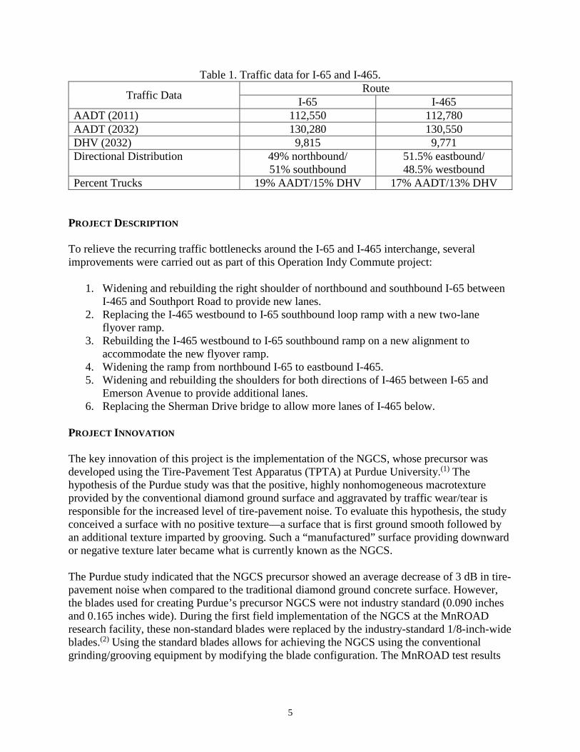
Table 1. Traffic data for I-65 and I-465.
Traffic Data Route I-65 I-465
AADT (2011) 112,550 112,780 AADT (2032) 130,280 130,550 DHV (2032) 9,815 9,771 Directional Distribution 49% northbound/
51% southbound 51.5% eastbound/ 48.5% westbound
Percent Trucks 19% AADT/15% DHV 17% AADT/13% DHV PROJECT DESCRIPTION To relieve the recurring traffic bottlenecks around the I-65 and I-465 interchange, several improvements were carried out as part of this Operation Indy Commute project:
1. Widening and rebuilding the right shoulder of northbound and southbound I-65 between I-465 and Southport Road to provide new lanes.
2. Replacing the I-465 westbound to I-65 southbound loop ramp with a new two-lane flyover ramp.
3. Rebuilding the I-465 westbound to I-65 southbound ramp on a new alignment to accommodate the new flyover ramp.
4. Widening the ramp from northbound I-65 to eastbound I-465. 5. Widening and rebuilding the shoulders for both directions of I-465 between I-65 and
Emerson Avenue to provide additional lanes. 6. Replacing the Sherman Drive bridge to allow more lanes of I-465 below.
PROJECT INNOVATION The key innovation of this project is the implementation of the NGCS, whose precursor was developed using the Tire-Pavement Test Apparatus (TPTA) at Purdue University.(1) The hypothesis of the Purdue study was that the positive, highly nonhomogeneous macrotexture provided by the conventional diamond ground surface and aggravated by traffic wear/tear is responsible for the increased level of tire-pavement noise. To evaluate this hypothesis, the study conceived a surface with no positive texture—a surface that is first ground smooth followed by an additional texture imparted by grooving. Such a “manufactured” surface providing downward or negative texture later became what is currently known as the NGCS. The Purdue study indicated that the NGCS precursor showed an average decrease of 3 dB in tire-pavement noise when compared to the traditional diamond ground concrete surface. However, the blades used for creating Purdue’s precursor NGCS were not industry standard (0.090 inches and 0.165 inches wide). During the first field implementation of the NGCS at the MnROAD research facility, these non-standard blades were replaced by the industry-standard 1/8-inch-wide blades.(2) Using the standard blades allows for achieving the NGCS using the conventional grinding/grooving equipment by modifying the blade configuration. The MnROAD test results
6
validated that the field implementation of NGCS with standard blades could reproduce Purdue’s precursor with similar reduction in pavement noise. In general, there are two grinding/grooving configurations that can be used to create the NGCS:
1. Single pass NGCS: For this configuration, three smaller diameter blades are stacked between two blades that are approximately 0.08 inches larger in radius. The smaller blades provide the smooth ground surface, and the larger blades provide the grooving for the negative texture with 0.5-inch center-to-center spacing.
2. Two pass NGCS: This configuration first creates a smooth concrete surface using only the smaller diameter blades. Then, a second pass of the grinding equipment is made with the larger blades separated by spacers to create 0.5-inch center spacing.
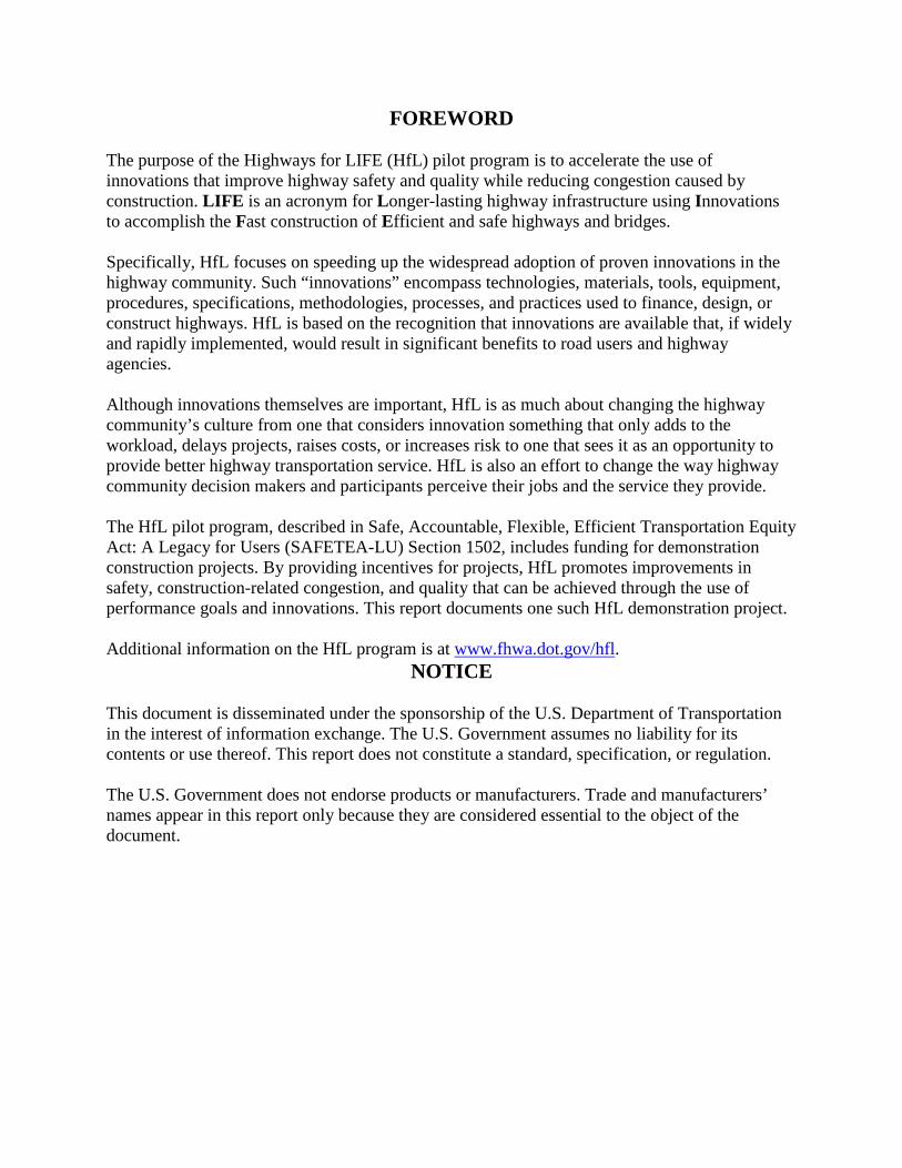
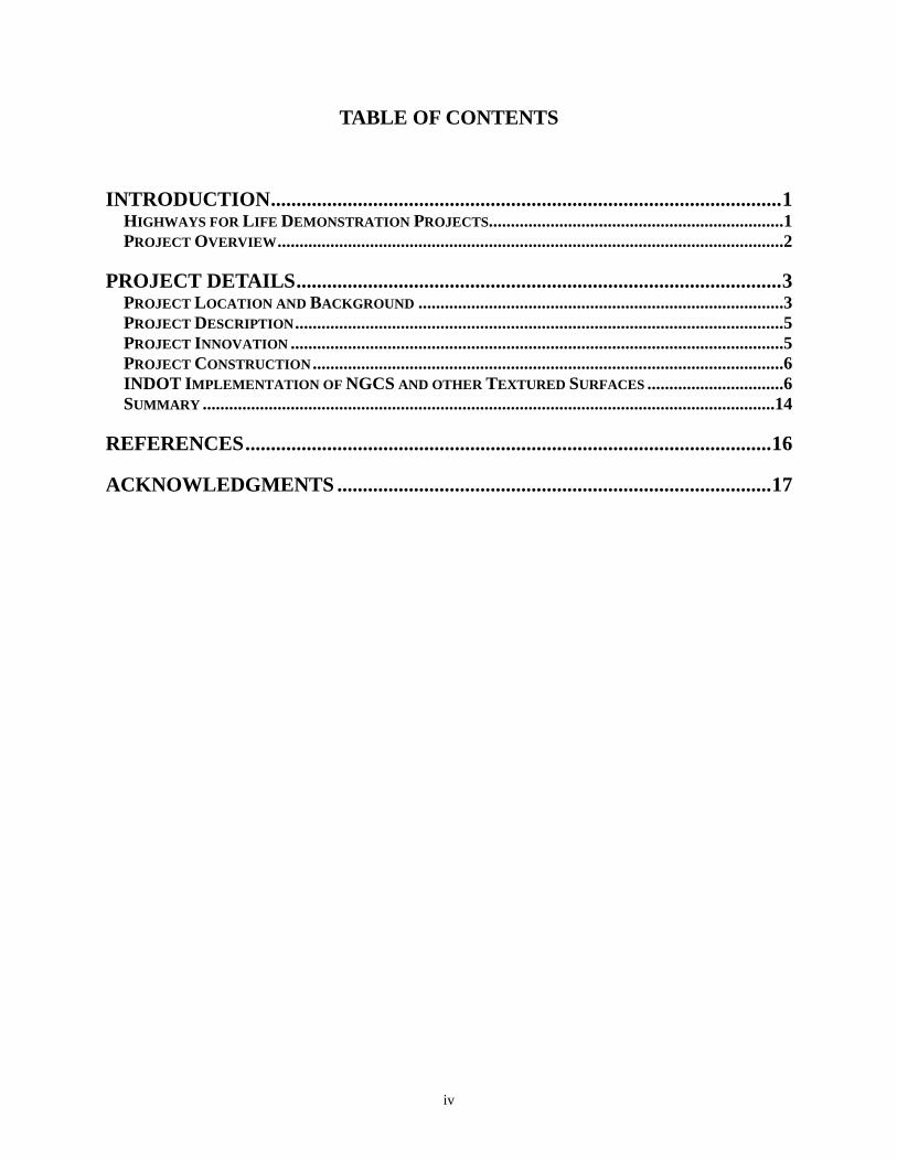
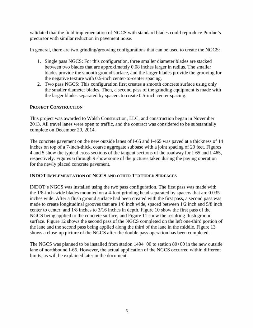
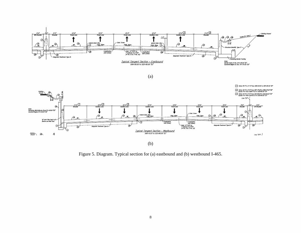
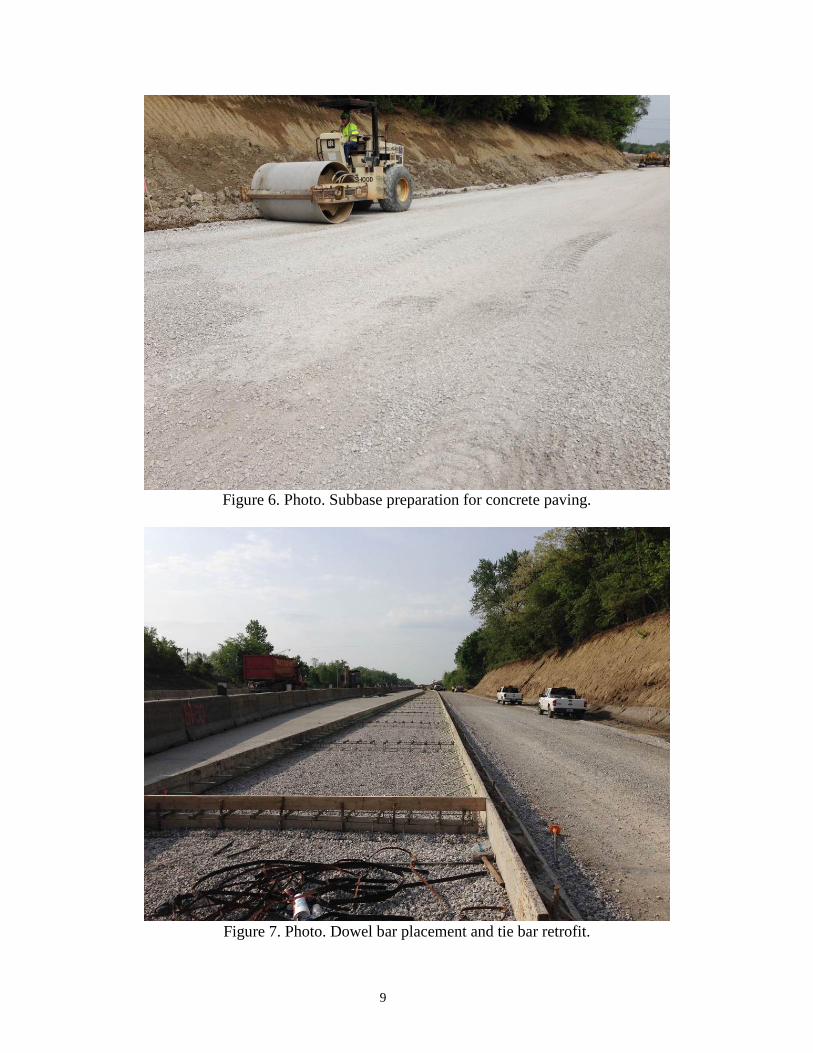
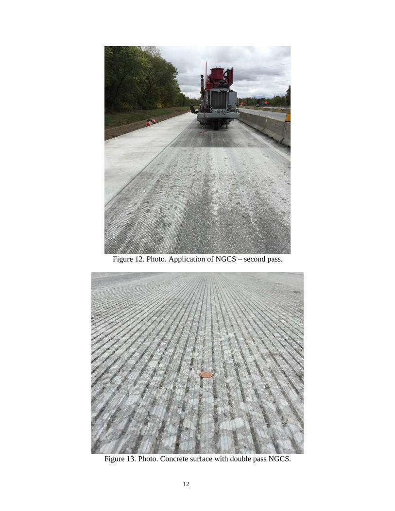
PROJECT CONSTRUCTION This project was awarded to Walsh Construction, LLC, and construction began in November 2013. All travel lanes were open to traffic, and the contract was considered to be substantially complete on December 20, 2014. The concrete pavement on the new outside lanes of I-65 and I-465 was paved at a thickness of 14 inches on top of a 7-inch-thick, coarse aggregate subbase with a joint spacing of 20 feet. Figures 4 and 5 show the typical cross sections of the tangent sections of the roadway for I-65 and I-465, respectively. Figures 6 through 9 show some of the pictures taken during the paving operation for the newly placed concrete pavement. INDOT IMPLEMENTATION OF NGCS AND OTHER TEXTURED SURFACES INDOT’s NGCS was installed using the two pass configuration. The first pass was made with the 1/8-inch-wide blades mounted on a 4-foot grinding head separated by spacers that are 0.035 inches wide. After a flush ground surface had been created with the first pass, a second pass was made to create longitudinal grooves that are 1/8 inch wide, spaced between 1/2 inch and 5/8 inch center to center, and 1/8 inches to 3/16 inches in depth. Figure 10 show the first pass of the NGCS being applied to the concrete surface, and Figure 11 show the resulting flush ground surface. Figure 12 shows the second pass of the NGCS completed on the left one-third portion of the lane and the second pass being applied along the third of the lane in the middle. Figure 13 shows a close-up picture of the NGCS after the double pass operation has been completed. The NGCS was planned to be installed from station 1494+00 to station 80+00 in the new outside lane of northbound I-65. However, the actual application of the NGCS occurred within different limits, as will be explained later in the document.

7
(a)
(b)
Figure 4. Diagram. Typical section for (a) northbound and (b) southbound I-65.
8
(a)
(b)
Figure 5. Diagram. Typical section for (a) eastbound and (b) westbound I-465.
9
Figure 6. Photo. Subbase preparation for concrete paving.
Figure 7. Photo. Dowel bar placement and tie bar retrofit.

10
Figure 8. Photo. Placement of fresh concrete.
Figure 9. Photo. Tube rolling of concrete material.

11
Figure 10. Photo. Application of NGCS – first pass.
Figure 11. Photo. Flush ground surface created by first pass of NGCS.
12
Figure 12. Photo. Application of NGCS – second pass.
Figure 13. Photo. Concrete surface with double pass NGCS.

13
In addition to the NGCS, INDOT implemented three other concrete textures so that a comparison can be made in terms of installation cost and pavement noise reduction to evaluate their feasibility as an alternative to the noise walls. These additional textures are:
1. INDOT’s conventional transverse tining, installed from station 1494+00 to station 1441+00 in the new southbound outside lane of I-65 (Figure 14). This conventional tining first requires a double thickness burlap drag or a minimum 4-foot-wide turf drag, followed by a tining operation to generate transverse grooves that are between 3/32 inches and 1/8 inch in width, between 1/8 inch and 3/16 inches in depth, and of the following sequence for spacing: 5/8 inches, 1 inch, 7/8 inches, 5/8 inches, 1 1/4 inches, 3/4 inches, 1 inch, 1 inch, 1 inch, 1 inch, 3/4 inches, 7/8 inches, 1 3/4 inches, 7/8 inches, 3/8 inches, 1 inch, 1 inch, 1 1/4 inches, 1 1/2 inches, 7/8 inches, 3/4 inches,7/8 inches, 1 inch, 7/8 inches, 1 inch.
2. INDOT’s modified transverse tining, from station 80+00 to station 1494+00 in the new
southbound outside lane of I-65. This tining finish is identical to the above conventional tining, with the only difference being the spacing of the tines that are in the following sequence: 3/8 inches, 9/16 inches, 5/8 inches, 7/16 inches, 3/8 inches, 1/2 inches, 9/16 inches, 5/8 inches, 7/16 inches, 3/8 inches, 13/16 inches, 1/2 inches, 3/8 inches.
3. Longitudinal tining of concrete surface, was planned to be installed from station 1441+00 to station 1494+00 in the new northbound outside lane of I-65 (Figure 15). The longitudinal tines are 1/8 inches wide and uniformly spaced at 3/4-inch intervals. The depth of the groves range from 1/8 inches to 3/16 inches.
Figure 14. Photo. Concrete surface with INDOT’s traditional transverse tining finish.

14
Figure 15. Photo. Concrete surface with longitudinal tining finish.
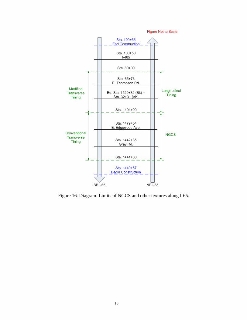
As mentioned earlier, the NGCS was planned to be installed between stations 1494+00 and 80+00 in the new outside lane of northbound I-65. However, the maintenance of traffic that was set up within these limits did not provide sufficient room to maneuver the NGCS equipment. Therefore, the section limits for the NGCS and the longitudinal tining were swapped. Figure 16 shows the approximate limits of the four different textures implemented on the new outside lanes of I-65, in relation to project station numbers and other streets. INDOT’s conventional transverse tining was applied for all other locations where new slabs of concrete were placed. SUMMARY The overall objective of this project was to improve the traffic flow and relieve the recurring commuting bottlenecks around the I-65 and I-465 interchange. The project involved widening of the I-65 and I-465 mainline and several ramps and construction of a new flyover ramp from westbound I-465 to southbound I-65. The key innovation of this project was the implementation of the NGCS. Three other concrete texturing techniques were implemented to study their effect on noise reduction.
15
Figure 16. Diagram. Limits of NGCS and other textures along I-65.

16
REFERENCES 1. Dare, T., Thornton, W., Wulf, T., Bernhard, R., “Acoustical Effects of Grinding and
Grooving on Portland Cement Concrete Pavements.” Final Report HL 2009-1, Purdue University’s Institute of Safe, Quiet, and Durable Highways, 2009.
2. Scofield, L., “Development and Implementation of the Next Generation Concrete Surface.” Final Report, American Concrete Pavement Association, 2012.

17
ACKNOWLEDGMENTS The project team acknowledges the invaluable insights and guidance of Highways for LIFE Team Leader Byron Lord and Program Coordinator Ewa Flom, who served as the technical panel on this demonstration project. Their vast knowledge and experience with the various aspects of construction, technology deployment, and technology transfer helped immensely in developing both the approach and the technical matter for this document. The team also is indebted to INDOT Engineers John Reeves, Tommy Nantung, and Mark Miller and FHWA Engineer Tom Duncan and Division Leader Jay DuMontelle, for their advice and assistance during this project.


