54
INDIANA LTAP ROAD SCHOLAR CORE COURSE #10 CULVERT DRAINAGE Presented by Thomas T. Burke, Jr., PhD, PE Luke J. Sherry, PE, CFM Christopher B. Burke Engineering, Ltd.
INDIANA LTAP
ROAD SCHOLAR CORE COURSE #10
CULVERT DRAINAGE
Presented by
Thomas T. Burke, Jr., PhD, PE
Luke J. Sherry, PE, CFM
Christopher B. Burke Engineering, Ltd.

OBJECTIVES
• Review culvert shapes, end
sections, and materials
• Types of culvert flow conditions
• Steps to determine culvert size
• HY-8
• Examine culvert material and
shape selection
2

CULVERT FLOW
Conditions
• Full flow (flow under pressure)
• Partially full (free surface)
• Combination
3

VARIABLES
• Inlet geometry
• Roughness
• Slope
• Pipe Diameter
• Length
• Headwater (approach) or tailwater conditions
Flow is dependent upon:
4

CULVERT SHAPES
AND MATERIALS
Typical Materials:
• Corrugated Metal Pipe • High-Density Polyethylene
• Concrete • Ductile Iron Pipe (DIP)
• Polyvinyl Chloride (PVC) Pipe • Clay
5

CONCRETE
Concrete Arch
Tripe Reinforced Concrete Box
Culverts (RCBCs)
Triple Concrete Circular6

PLASTIC &
METAL
Corrugated Metal Arch
High-Density
Polyethylene (HDPE)
Corrugated Metal Circular7

ROUGHNESS COEFFICIENTS
Source: InDOT Design Manual
n = Manning’s roughness coefficient
8

END SECTIONS
9

ENTRANCE LOSS
COEFFICIENTS
Source: InDOT Design Manual
10

RIPRAP
11
Source: InDOT Design Manual
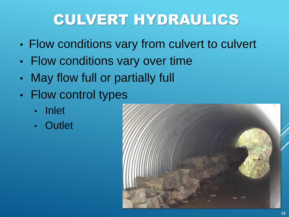
CULVERT HYDRAULICS
• Flow conditions vary from culvert to culvert
• Flow conditions vary over time
• May flow full or partially full
• Flow control types
• Inlet
• Outlet
12

HEADWATER AND TAILWATER
• Headwater (HW) - Depth of upstream water surface measured
from invert of culvert entrance
• Should not exceed edge of roadway shoulder elevation
to allow for freeboard
• Should not be so high as to cause flooding upstream
• Tailwater (TW) - Depth of downstream water surface measured
from invert of culvert outlet
• For stream crossings, usually determined by backwater
calculations through hydraulic modeling
• H = Difference in elevation
of upstream pool level and
the water surface at the
culvert outlet
Headwater
TailwaterH
13

INLET CONTROL
• Culvert inlet controls (or limits) the flow
• More difficult for flow to get through the
entrance of the culvert than it is to flow
through the remainder of the culvert
14

INLET CONTROL - A
• Pipe flow is partially full
• Outlet not submerged
15
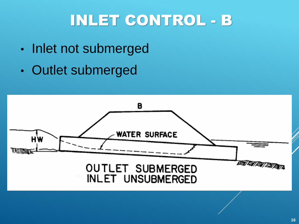
INLET CONTROL - B
• Inlet not submerged
• Outlet submerged
16
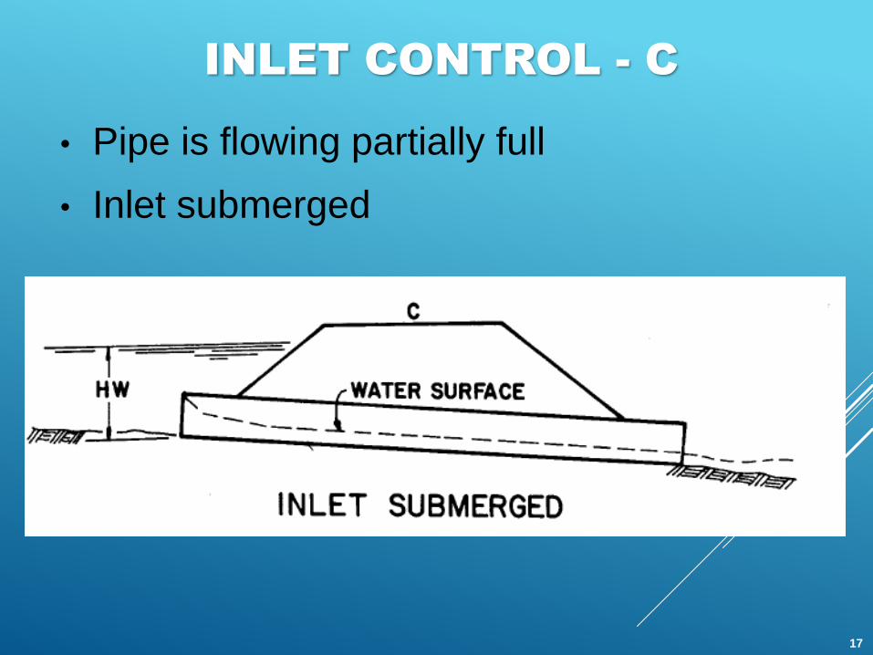
INLET CONTROL - C
• Pipe is flowing partially full
• Inlet submerged
17

OUTLET CONTROL
• Culvert barrel capacity or outlet controls
(or limits) the flow
• More difficult for flow to negotiate length
of culvert than it is to get through the inlet
(entrance)
18

OUTLET CONTROL - A
• Pressure flow
• Full Flow
• Inlet and outlet submerged
19

OUTLET CONTROL - B
• Submerged inlet
• Outlet not submerged
• Outlet velocities usually high
B
20

OUTLET CONTROL - C
• Submerged inlet
• Outlet not submerged
• Low TW
C
21

OUTLET CONTROL - D
• Inlet not submerged
• Outlet not submerged
D
22

CULVERT PERFORMANCE
FACTORS
Factor Inlet Control Outlet Control
Headwater Elevation X X
Inlet Area X X
Inlet Edge
Configuration
X X
Inlet Shape X X
Pipe Roughness X
Pipe Area X
Pipe Shape X
Pipe Length X
Pipe Slope X
Tailwater Elevation X
23

CULVERT DESIGN STEPS
1. Summarize known data: Flowrate (Q) in cfs, target upstream water
surface elevation
2. Choose the culvert dimensions (diameter, length)
3. Assume inlet control
4. Use chart to calculate the upstream total head (HW) for the design
flowrate using design table
5. Repeat step 3 until the upstream head (HW) satisfies design
specifications
6. Use design chart to calculate the head loss (H) from inlet to outlet
for the design flowrate
7. Calculate the upstream total head (HW = H + TW)
8. Compare the inlet and outlet control results
• The higher headwater governs and indicates the flow control
(inlet or outlet control)
24

EXAMPLE CALCULATION
Inlet Control Sheet
Diameter = 42” (3.5 ft)
Q=120 cfs
L=50 ft
Inlet submerged
25
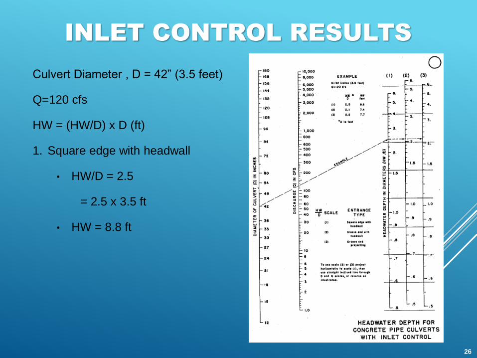
INLET CONTROL RESULTS
Culvert Diameter , D = 42” (3.5 feet)
Q=120 cfs
HW = (HW/D) x D (ft)
1. Square edge with headwall
• HW/D = 2.5
= 2.5 x 3.5 ft
• HW = 8.8 ft
26

EXAMPLE CALCULATION
Outlet Control Sheet
Diameter = 42” (3.5 ft)
Q=120 cfs
L = 50 ft
TW = 4.3 ft
From chart, H = 3.3’
HW = TW + 3.3’
HW = 4.3’ + 3.3’ = 7.6’
27

INLET CONTROL VS.
OUTLET CONTROL RESULTS
Culvert Diameter , D = 42” (3.5 feet)
Q=120 cfs
L = 50 feet
TW = 4.3 feet
INLET CONTROL
HW = (HW/D) x D (ft)
1. Square edge with headwall
• HW = 8.8’ ft
OUTLET CONTROL
HW = 7.6 ft
CONCLUSION: 8.8 ft > 7.6 ft
inlet controlled, use
inlet control answer
28

HY-8
• Federal Highway Administration culvert analysis program
• Yields headwater rating curve (elevation, Q relationship)
• Parameters:
• Enter design Q
• Culvert length
• Culvert shape and roughness
• Entrance type
• Overtop elevation (road profile)
• Additional inputs:
• Tailwater rating curve
29

HY-8 EXAMPLE PROBLEM #1
The design information for this site is summarized by the following:
HYDROLOGY
100-Year Peak Flowrate is 65 cfs (Based on WinTR-20 Hydrologic
Model of Tributary Area)
SITE DATA
Upstream invert elevation = 661.15 ft.
Downstream invert elevation = 659.00 ft.
Culvert length = 120 ft.
Culvert will project from headwall
No depression at conventional-type inlet
Use HY-8 to determine the size of a culvert required fora proposed road crossing. The local ordinance specifiesthat culverts be sized to pass the 100-year peakflowrate and also provide two feet of freeboard.
30
HY-8 EXAMPLE PROBLEM #1
(CONTINUED)
WATERWAY DATA
Input existing channel information to model tailwater conditions acting on the culvert.
ROADWAY DATA
Roadway overtopping elevation is 667.0 (Determined from proposed roadway profile).
Proposed roadway is 80 feet wide.
31

Proposed Roadway
Existing Ditch
Tributary Area = 56 Acres
CN = 81
Tc = 41 min
Q100 = 65 cfs (from Win TR-20)
HY-8 EXAMPLE PROBLEM #1
(CONTINUED)
32

HY-8: CREATING A
NEW PROJECT
HY-8 Introduction Screen33
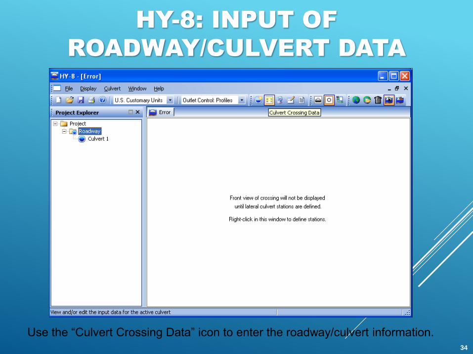
HY-8: INPUT OF
ROADWAY/CULVERT DATA
Use the “Culvert Crossing Data” icon to enter the roadway/culvert information.34

HY-8: INPUT OF CULVERT DATA
HY-8 Crossing Data Screen35

HY-8: INPUT OF DISCHARGE DATA
Input of Discharge Data – Enter the design and maximum flow.36

HY-8: INPUT OF TAILWATER DATA
Input of Tailwater Data – Note that we will input site-specific channel
Information to model tailwater conditions for this example. 37

HY-8: INPUT OF TAILWATER DATA
Input of Tailwater Data – Channel Geometry Based on Topography
38
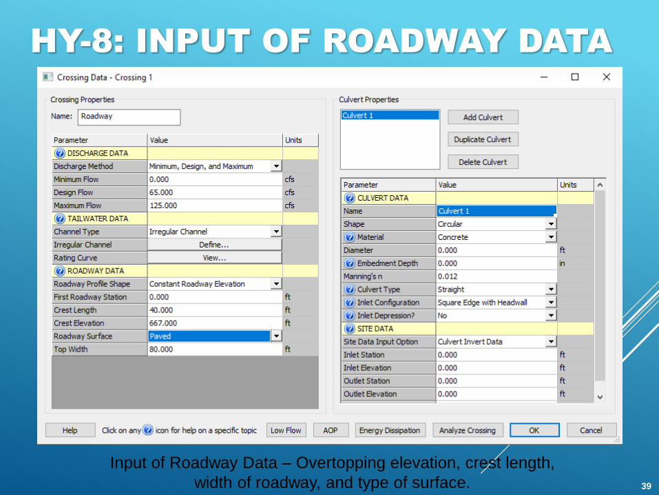
HY-8: INPUT OF ROADWAY DATA
Input of Roadway Data – Overtopping elevation, crest length,
width of roadway, and type of surface. 39

HY-8: INPUT OF ROADWAY DATA
HY-8 uses the weir equation to calculate flow over a roadway.
When the user specifies a constant roadway elevation with a specified crest length
(L), HY-8 will calculate the flow using the rectangular weir equation (Q = Cd*L*H3/2). If
input discharge coefficient is selected, the user will enter a discharge coefficient
between 2.5 and 3.095.
For a user-defined (irregular) roadway, HY-8 calculates a weighted average of the L
and H terms in the weir equation:
40

HY-8: INPUT OF CULVERT DATA
Input of Culvert Data – Note that a 36-inch (3-foot) diameter culvert was used.41

HY-8: INPUT OF SITE DATA
Input of Site Data – Culvert length, inverts, and number of barrels.42

HY-8: RUNNING THE
CULVERT ANALYSIS
The “Run Analysis” icon on the toolbar performs the culvert analysis.43

HY-8: VIEWING THE OUTPUT
Output for Example #1 – Does the proposed culvert meet the design requirements?
44

HY-8: VIEWING THE OUTPUT
Upsizing the culvert is an option to meet requirements.
45

HY-8: VIEWING THE OUTPUT
Output for Example #1 – Note that the headwater elevation at the design
flowrate (664.84 ft) is 2.16 feet below the roadway overtopping (667.0 ft).46
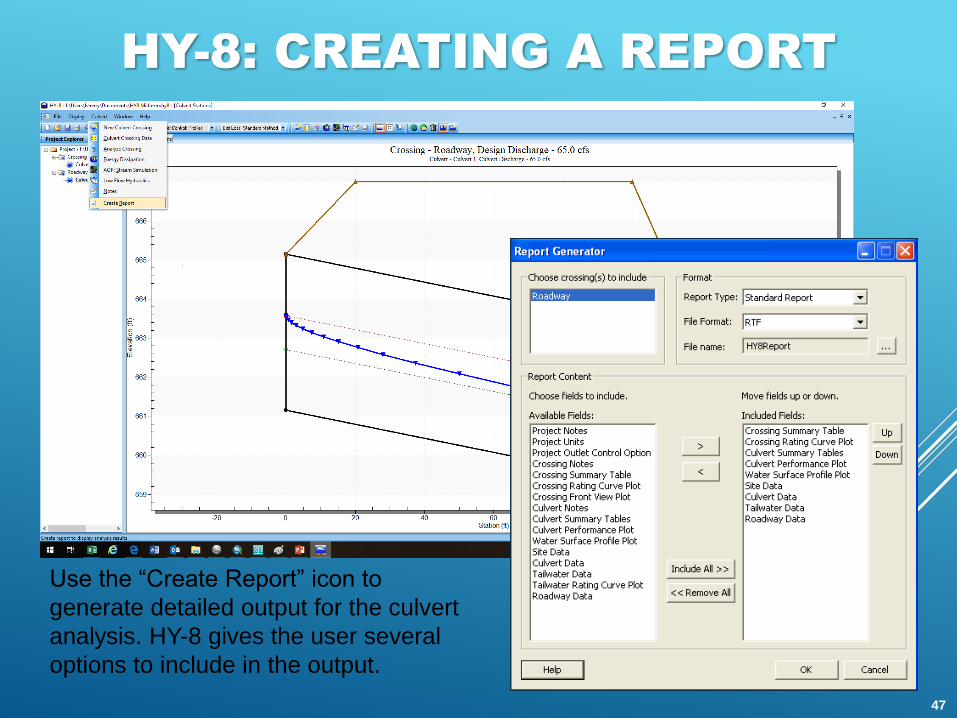
HY-8: CREATING A REPORT
Use the “Create Report” icon to
generate detailed output for the culvert
analysis. HY-8 gives the user several
options to include in the output.
47
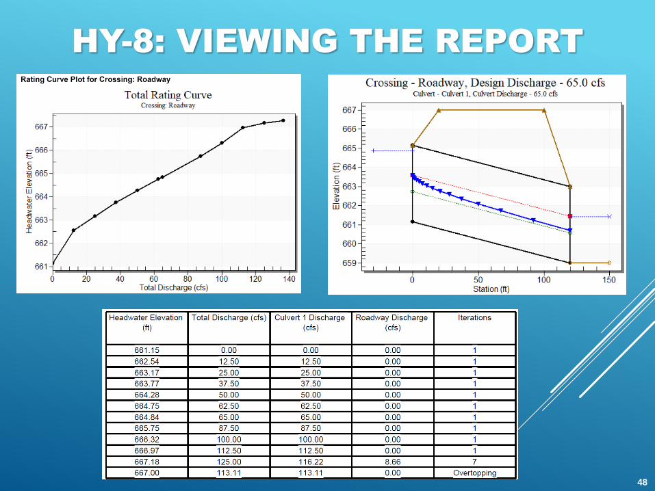
HY-8: VIEWING THE REPORT
48
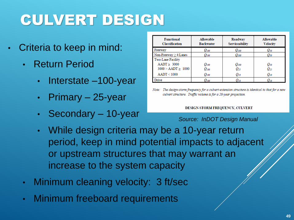
CULVERT DESIGN
• Criteria to keep in mind:
• Return Period
• Interstate –100-year
• Primary – 25-year
• Secondary – 10-year
• While design criteria may be a 10-year return
period, keep in mind potential impacts to adjacent
or upstream structures that may warrant an
increase to the system capacity
• Minimum cleaning velocity: 3 ft/sec
• Minimum freeboard requirements
Source: InDOT Design Manual
49

CULVERT SHAPE
SELECTION
• Criteria to keep in mind:
• Minimum pipe size
• Site / location restrictions – what fits?
What about installation?
• County / community ordinance guidelines
• Cost
Source: InDOT Design Manual
50

CULVERT MATERIAL
SELECTION
• General criteria:
• Loading / cover over the pipe
• Minimum cover is typically 2 feet; however, check applicable regulations
• Boone County, IN requires 3 feet for culverts within ROW
• Purpose
• Drain tile versus highway crossing
• County / community ordinance guidelines
• Are plastic pipes allowed?
• Is concrete required?
• Cost
51

INSTALLATION
• Plan and specifications signed by a Licensed PE
• Permits
• Best Management Practices (BMPs)
• Inlet and outlet protection
• Bedding materials
• Backfill
• Inspection
52

REFERENCES
• LTAP Stormwater Drainage Manual
• InDOT Design Manual
• HY-8 Users Manual (FHWA)
53

QUESTIONS


