Indicator/Turn Signals Schematics Hover over a wire to confirm the colour 1962 - 67 1967 on 1962-67 1967 on (for cars without hazard flashers the Green goes direct from fuse box to turn flasher) Note that late UK cars seem to have a subdivision of the green circuit with its own in-line 35 amp fuse supplied by the white/brown (ignition relay) circuit feeding things like heated rear window turn signals heater fan and tach which leaves the original green circuit fuse (2nd one up in the four-way fuse block) feeding things like reverse lights stop lights washers wipers and circuits associated with the seat belt warning lamp and time delay buzzer. Page 1 of 140 10 January 2015
Transcript
Indicator/Turn Signals Schematics Hover over a wire to confirm the colour
1962-67 1967 on
1962-67
1967 on (for cars without hazard flashers the Green goes direct from fuse box to turn flasher)
Note that late UK cars seem to have a subdivision of the green circuit with its own in-line 35 amp fuse supplied by the white/brown (ignition relay) circuit feeding things like heated rear window turn signals heater fan and tach which leaves the original green circuit fuse (2nd one up in the four-way fuse block) feeding things like reverse lights stop lights washers wipers and circuits associated with the seat belt warning lamp and time delay buzzer.
Page 1 of 140
10 January 2015
Hazard Warning Schematics Hover over a wire to confirm the colour
Flasher Internals Typical indicator (turn) and hazard flasher units - a 'no name' indicator unit on the left and an original Lucas 9FL hazard unit on the right. An original Lucas indicator unit would be marked '8FL'. The indicator unit is marked '21W x 2 = 5w' which indicates it can power two 21w flasher bulbs plus one optional 5w bulb e.g. a wing repeater as used on some other cars. The dashboard tell-tale will be in addition to this if course but is only 2.2W. The hazard unit is marked with the model number '35053' the week and year of manufacture '11 80' (this came off a 1980 car) and '12A max' which is the maximum current loading. A pair of flasher bulbs i.e. the indicators draws about 3.5A so four hazard flasher bulbs will draw about 7A, and if a trailer is connected about 10.5A, which gives a 'safety factor' for wing repeaters, tell-tales etc.:
Page 2 of 140
10 January 2015
A general view of the indicator unit with main features labelled. The heating element is a low-resistance strip laid along the bimetallic strip of the moving contact.
Showing the normally-closed contacts. With indicator units there is a very low resistance path through the heating element and closed contact in series so the indicator bulbs light immediately the switch is operated. Once the element has heated up the contact opens which cuts off current flow through both lamps and heating element and the unit starts clicking 'off-on-off-on'. This type of unit is very susceptible to current flow. With one indicator bulb failed the current is halved, ditto the heating effect, and so the contact fails to open. But this gives a clear indication of a problem and easy diagnosis (at least of which corner the problem lies) since the working lamp remains glowing. However it is so sensitive to current that it doesn't take much of a drop in voltage (i.e. lots of electrical things switched on) or current (i.e. a few slightly high resistance connections) for the unit to start flashing slower or not at all in this case with both corners lit.
This particular example had failed. When the case was removed it was apparent that the heating element had broken
Page 3 of 140
10 January 2015
in the middle so current was flowing through only one half of it. This probably wouldn't have generated enough heat to cause the bi-metallic strip to flex enough to open the contact so the lights should have glowed continuously. But the actual symptom seems to have been that the lights didn't glow at all. However only minimal pressure was required to open the contacts so maybe before opening it and poking around they were just open hence no lights. Normally the springy-ness of the bi-metallic strip should have held the contacts closed until heat from the element caused it to flex enough to 'ping' open with the characteristic clicking when the unit is operating. Incidentally on this failed unit the braided connection to the heating element has been pulled out to show the ends of the broken element more clearly. If this comes into contact with the inside of the can (there is no insulation) which when installed is in the spring-clip which happens to be screwed to the bulkhead and so is earthed at the very least it will blow the fuse. In fact it may well burn out the element first as it glows red-hot just under the load of the lamps.
Lucas hazard flasher showing the heating element running diagonally across the bi-metallic strip with additional resistance wire wrapped round the element.
Page 4 of 140
10 January 2015
Showing the normally-open contacts. Because hazard flashers are designed to flash at a relatively constant rate no matter how many bulbs are left working after say an accident, and with falling battery voltage from being left flashing for a long time, they are designed differently to indicator flashers. The relatively high resistance winding and element is connected across the open contacts, doesn't pass enough current to make the lamps glow, and the current varies relatively little as long as at least one bulb is still working. When the element has heated the bimetallic strip the contact pings closed which shorts out the heating element (which starts cooling down) and lights the lamps, and the unit starts clicking 'on-off-on-off'.
Page 5 of 140
10 January 2015
Diagnosing Slow or Non-flashing Indicators
This schematic shows all the connection points as well as the components in the flasher circuit. The numbers in red show the order of tests from the battery through to the bulbs: 1, 2, 3 etc. as the main tests, n.1, n.2 n.3 etc. as supplementary tests where required.
Page 6 of 140
10 January 2015
Note that chrome bumper light unit body earths are shared with the parking lights (front and rear) so if the body earth is bad then with the parking lights on the indicators will be worse. Rubber bumper front indicators similarly share their wired earth with the pilot parking lights in the headlights, so again if the bullets by the headlight or the body earth are bad the indicators will be worse with the parking lights on.
By plotting the measured voltages on this chart it should be easy to see where the worst bad connections are, and hence the ones to be tackled first for the greatest improvement. Click here to display a copy of the chart for printing.
Whilst the list is in a logical order from battery to bulbs it makes sense to test the battery and points 10 and 11 first in order to identify which corner or corners need closer inspection.
About the only connection these tests don't take account of is that between the centre contact of the bulb and the bulb holder. Not possible to get at without removing the bulb, by which time you might as well clean the holder contact and check the bulb contact anyway. I've noticed the the solder blob which forms the bulb connection has worn down on old bulbs, this will tend to reduce the spring tension on that contact from the holder contact.
Page 7 of 140
10 January 2015
Diagnosing Slow or Non-flashing Indicators
Notes:
There will inevitably be some reduction in voltage as you work through the circuit from battery to the corners of the car. Go through the main test points 1, 2, 3, 4 etc. until you find a significant reductionthen go back and do the intermediate test points n.1, n.2, n.3 etc. to find the connection causing the problem.
1. The fusebox brown is a convenient point to check the voltage on the brown to the ignition switch. If this shows a volt-drop from the battery you need to check connections at the solenoid where the brown wires join the battery cable.
2. As with all multi-plugs, test both sides in case the connection between the two halves is at fault.
Test Order Test Voltage Note Diff.
1 Battery
1.1 if 2 bad Solenoid stud
2 Fusebox brown 1
2.1 if 3 bad Ignition switch multiplug brown 2
2.2 if 3 bad Ignition switch multiplug brown 2
2.3 if 3 bad Ignition switch brown
2.4 if 3 bad Ignition switch white
2.5 if 3 bad Ignition swith multiplug white
2.6 if 3 bad Ignition swith multiplug white
2.7 if 3 bad White from main to rear 1
2.8 if 3 bad White from main to rear 2
3 Fusebox white spade
3.1 if 4 bad Fusebox white fuse holder 3
3.2 if 4 bad Fusebox white fuse endcap 3
3.3 if 4 bad Fusebox green fuse endcap 3
3.4 if 4 bad Fusebox green fuse holder 3
4 Fusebox green spade
4.1 if 5 bad Green bullets behind dash (can be several) 4
4.2 if 5 bad Hazard switch (where fitted) green 1
4.3 if 5 bad Hazard switch (where fitted) green 2
5 Flasher green linked to green/brown
5.1 if 6 and 7 bad Indicator switch multi-plug green/brown 1
5.2 if 6 and 7 bad Indicator switch multi-plug green/brown 2
5.3 if 6 and 7 bad Indicator switch green/brown
Sides of car Right Left
5.4 if 6 and 7 bad Indicator switch green/red and green/white
5.5 if 6 and 7 bad Indicator switch multi-plug green/red and green/white 1
5.6 if 6 and 7 bad Indicator switch multi-plug green/red and green/white 2
6 Green/red and green/white bullets from main by fusebox 1 5
7 Green/red and green/white bullets from main by fusebox 2 5
8 Green/red and green/white bullet to rear by fusebox
Corners of car RF LF RR LR
9 Green/red and green/white to green 1
10 Green/red and green/white to green 2
Earth tests 6
11 Bulb base
11.1 if 11 bad Bulb holder
11.2 if 11 bad Light unit base
11.3 if 11 bad RB bullet by headlight 1
11.4 if 11 bad RB bullet by headlight 2
12 RB body earth 7
Page 8 of 140
10 January 2015
Adding Hazard Flashers
A suitable position on the centre console
Page 9 of 140
10 January 2015
I prefer the pukka switches ...
... but they have round pins instead of flat spades
Page 10 of 140
10 January 2015
One of the multi-way sockets from an old 1980 harness has the right spacing when cut into a block of four and a block of two
Pins pushed out of the blocks ...
Page 11 of 140
10 January 2015
... a 2mm drill ...
... opens up the crimps ...
... and the old insulation and copper strands removed.
Page 12 of 140
10 January 2015
Blocks and pins ready for wires ...
... wire soldered over the inner conductor crimp ...
... and the outer crimp closed over the insulation.
Page 13 of 140
10 January 2015
Afrter all that I found this from Autosparks which looks like it should fit.
Connectors added to the other ends of the wires as required ...
... and taped with harness wrap.
Page 14 of 140
10 January 2015
The new sub-harness is fed through ...
... and the switch attached.
Page 15 of 140
10 January 2015
Power supply with in-line fuse for hazard flasher
Optional clip to mount the flasher unit on the bulkhead beside the indicator flasher (image from Brown & Gammons)
Page 16 of 140
10 January 2015
Connect up, turn on ...
... and Bee has hazard flashers.
Page 17 of 140
10 January 2015
Louder Indicator Sounder
If you use piggy-back spade connectors on the wires from the buzzer you can connect and remove it simply by unplugging spades, no cutting or soldering of wires.
Indicator/Turn Switch
Page 18 of 140
10 January 2015
Switch from 62-68
The following pictures show the detail of a switch from a 1973. Switch in the cancelled position showing the contact fingers clear of the contact rivets. The fingers are the 'common' contact with the light-green/brown wire coming from the flasher unit, the rivets are connected to the green/red and green/white wires going to the left and right respectively corners of the car.
Switch turned to the right, stalk down and upper contact (when installed) closed. Also showing the cancelling fingers. When the switch is operated one of the cancelling fingers is moved closer to the column and the other further away. When the wheel is turned far enough from the straight-ahead a peg or cam on the steering column brushes under the finger lifting it and dropping it back with an audible click. When the wheel is turned back towards the straight-ahead position the peg or cam hits the tip of the finger pushing the switch back to the central position. In this position both fingers are clear of the peg or cam.
Page 19 of 140
10 January 2015
Switch turned to the left
Clip partially removed showing the spring (with ball behind) that latches the switch in each of the three positions
Page 20 of 140
10 January 2015
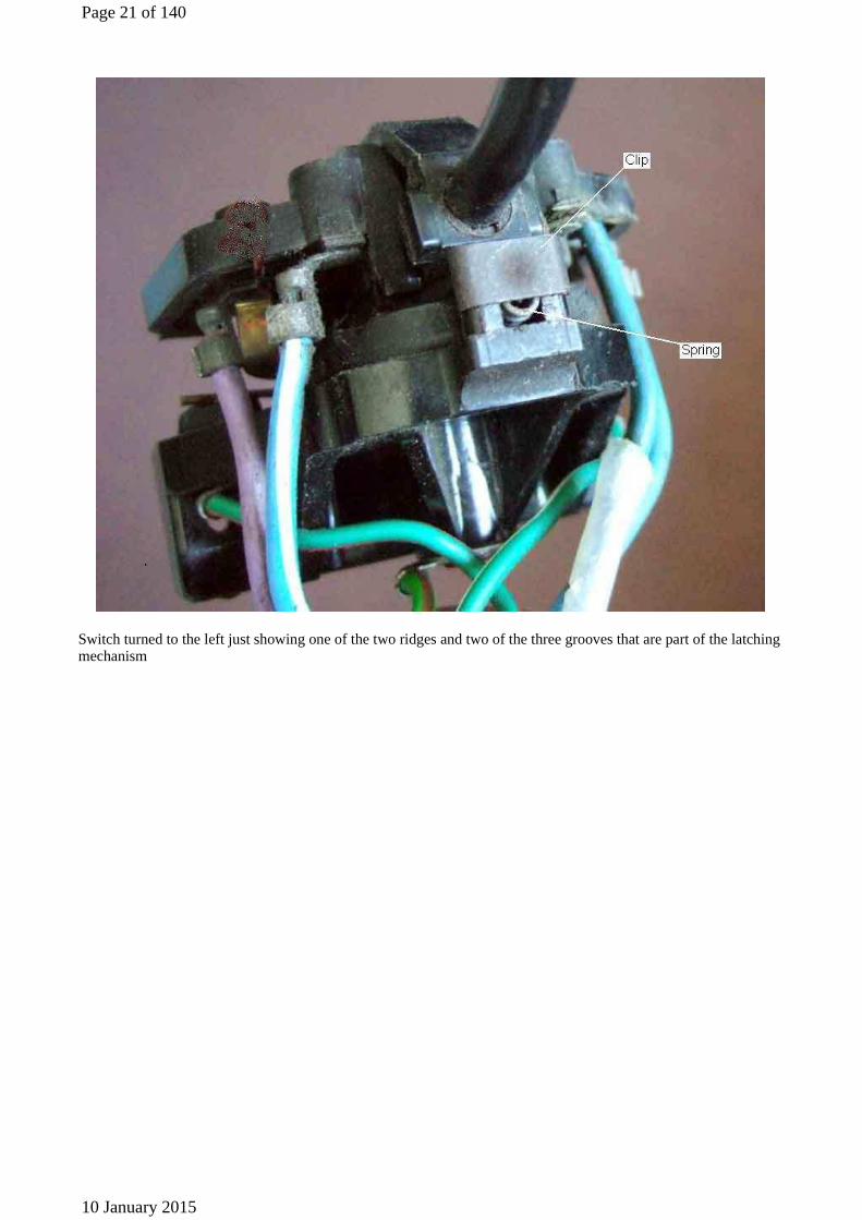
Switch turned to the left just showing one of the two ridges and two of the three grooves that are part of the latching mechanism
Page 21 of 140
10 January 2015
Indicator/turn switch in the cancelled i.e. central position, wheel straight-ahead, which puts the cancelling cam between the cancelling fingers. Earlier cars had a cancelling peg screwed into the column instead of the cam shown here. To correct the cancelling position this cam can be slid around the column (it's a tight fit, obviously) but if the peg is in the wrong place the steering has to be split at the column UJ and the relative positions of the two shafts adjusted.
Page 22 of 140
10 January 2015
Indicator not operated, wheel turned to the left, cancelling cam under the cancelling finger but clear of it
Indicator operated to the left, wheel being turned left, the cancelling cam lifting the finger as it passes it
Page 23 of 140
10 January 2015
Indicator operated to the left, wheel has been turned left past the cancelling finger, now being straightened-up again. The cam hits the end of the finger and pushes the switch back into the central position again.
The connection of the common wire from the indicator flasher and the wires to the right and left sides
Page 24 of 140
10 January 2015
1977 and Later Indicator Cancelling
The 77 and on column switch arrangement. Both stalks are mounted on a common plate and there is a plastic or Nylon cancelling collar that, with the steering wheel removed, is free to rotate with respect to both the switch assembly and the steering shaft. With the wheels in the straight-ahead position, the collar needs to be orientated as shown with the cut-outs top and bottom and the rib pointing at the indicator/turn stalk, i.e. pointing to the right on RHD cars and the left on LHD cars. When the steering wheel is fitted I assume there are protrusions on the wheel boss that engage with the cut-outs in the switch cancelling collar, so care must be taken to align these. With the wheel fitted the wheel, column shaft and cancelling collar rotate as an item. If the cancelling collar is aligned to the wrong side it will take a much larger movement of the steering wheel before cancelling will occur. And if the wheel should happen to be fitted in other than the straight-ahead position the cancelling will be unbalanced between the sides.
Page 25 of 140
10 January 2015
An original late model wheel showing the protrusions on the back that engage with the slots in the cancelling collar of the switch.
An example of an after-market wheel boss. In this case it has two holes that I can utilise for a linking piece that will also engage with the cut-outs in the switch cancelling collar.
Page 26 of 140
10 January 2015
The metal linking piece that will engage with the two holes in the steering wheel boss and the two cut-outs in the switch cancelling collar.
The linking piece slid over the steering shaft and engaged with the slots in the switch cancelling collar. In fact it was easier to fit the linking piece to the steering wheel first, then carefully slide it on to the steering column.
Page 27 of 140
10 January 2015
Barrie's 'gizmo' ...
... attached to his wheel.
Page 28 of 140
10 January 2015
Main lights Hover over a wire to confirm the colour
Notes: 1: Parking lights were unfused on Mk I cars. Mk II cars for 68 and 69 had one in-line fuse for each end of the car. 2: Dip-switch moved from floor to column stalk for North America in 1968. 3: Blue/white is main beam, blue/red is dipped beam. 4. From 1967 to 1969 the front and rear parking lights were separately fused using in-line fuses, one fuse for the front and one for the back. 5. The 1968 and 69 model years may have had a courtesy light operated from the door switches as well as the map light and switch controlled by the side-lights.
Page 29 of 140
10 January 2015
Parking lights (70 on) Hover over a wire to confirm the colour
Note 1: Headlamp and instrument light wiring is much the same as for earlier cars, except that the dip-switch has now moved to the column stalk for all markets. Note 2: Map light deleted after 1970 (North America) or 1971 (UK). Note 3: 1970 (all) and 1971 (UK only) models may have had a courtesy light operated from the door switches as well as the map light and switch controlled by the side-lights. After that all models had the courtesy light controlled from door switches only. Note 4: Rubber bumper models (and North American 1974 models with the split rear bumper) have the number plate lights mounted on the number plate backing plate and wired grounds back to the bullets for the reversing lights.
Dip Switch
Showing the switch in the 'main beam' position, 'dip' and 'flash' contacts both open. This switch is from a UK 1973 model.
Page 30 of 140
10 January 2015
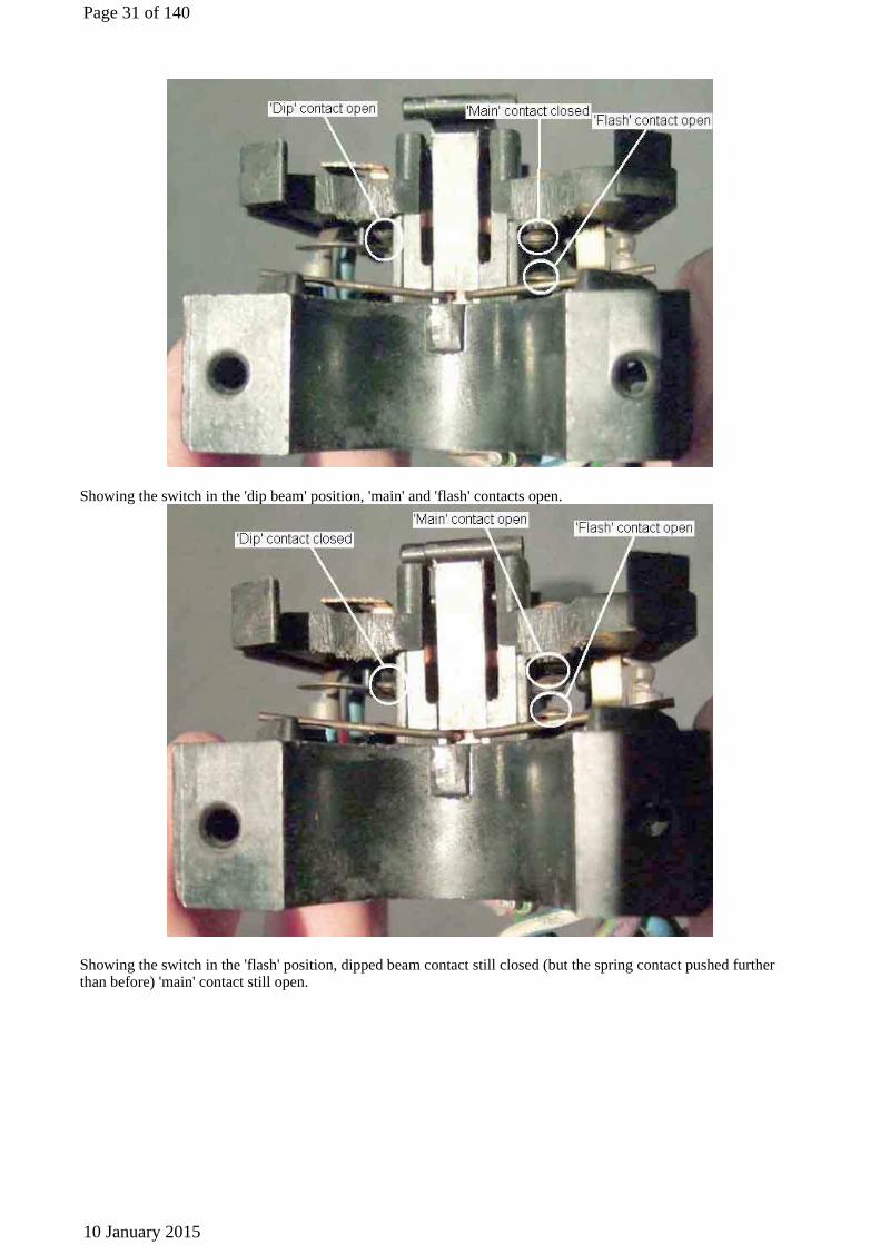
Showing the switch in the 'dip beam' position, 'main' and 'flash' contacts open.
Showing the switch in the 'flash' position, dipped beam contact still closed (but the spring contact pushed further than before) 'main' contact still open.
Page 31 of 140
10 January 2015
Showing the switch in the 'dip beam' position with the contacts labelled as to which colour wire goes where.
A general view showing the plastic springs (and indicator/turn-signal auto-cancel fingers) on the switch body. The 'Dip'/'Main' snap-action spring gives the positive switching action between dip and main positions. The 'Flash' spring gives a positive return to 'Dip' from 'Flash'.
Page 32 of 140
10 January 2015
Switch in the 'main beam' position, the flasher return spring clear of the switch body.
Switch in the 'dipped beam' position, the flasher return spring just touching the switch body.
Page 33 of 140
10 January 2015
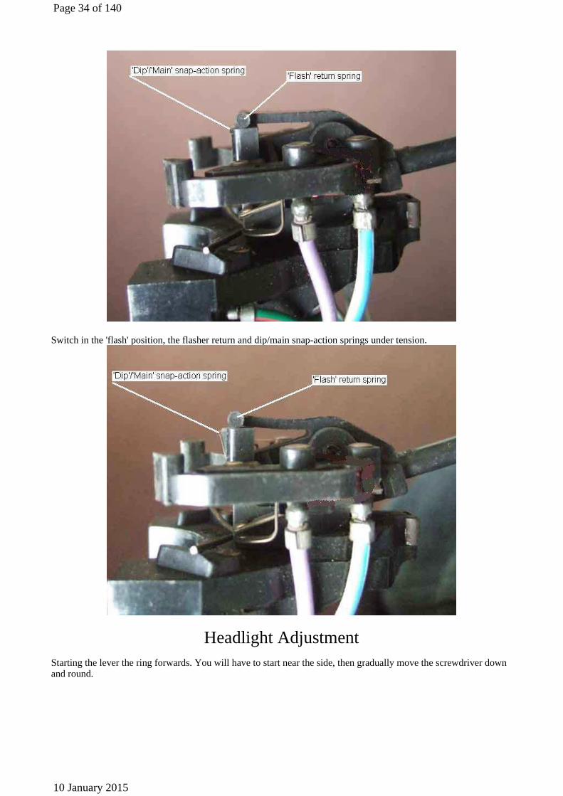
Switch in the 'flash' position, the flasher return and dip/main snap-action springs under tension.
Headlight Adjustment
Starting the lever the ring forwards. You will have to start near the side, then gradually move the screwdriver down and round.
Page 34 of 140
10 January 2015
The spring-clip stuck on the rear edge of the ring
Page 35 of 140
10 January 2015
How the clip should engage, and how it engages if left to its own devices. Even as it should be there is far too much engagement, making removal harder than it needs to be.
The spring clip, pulled downwards and forward once you have managed to get the ring off (left image), and where it needs to be to avoid getting jammed behind the lip on the rear of the ring.
If it looks like the clip is going to jam in the ring then probably the best bet is to pull the bottom of the ruing far enough forward so that it clears the bottom of the bowl, then carefully lift the top of the ring over one of the two raised portions that are at the top of the bowl. You will probably need a broad-bladed screwdriver to do this.
I have seen a recommendation to cut a section out of the lip at the bottom of the ring, slightly out of line with the spring when the ring is finally fitted. Then fit the ring so the cut-out goes over the spring, and rotate the ring into its final position. To remove rotate the ring so that the cut-out lines up with the spring, and it should pull forward more easily. However that involves cutting the ring, and the cut edge will rust, and my rings at least show now signs of rotating when fitted.
Probably the easiest I have had to deal with involved a bowl with the screw fitting as used on Minis etc, where a large, round-head screw goes up through a hole in the bottom of the ring into the fitting. By careful fitting and adjustment of the screw before fitting the ring you can set it such that the ring just goes over the head of the screw and holds the ring so it isn't loose. Ironically a replacement bowl for Vee came with the screw fitting, and I swapped it for the old clip which fortunately (or maybe not) was sound.
The various screws. The four fixing screws go through the wing and a thick reinforcing ring around the aperture. The three clamp screws hold the glass and reflector, or sealed beam unit, in the frame. The adjuster screws have slotted heads that engage in tabs in the frame, and the threads go through plastic nuts and into 'sockets' in the rubber sealing that protrude through the wing, the sockets keep dirt and moisture from getting onto the adjuster threads from behind the wing. The two raised sections that retain the top of the ring are arrowed.
Page 36 of 140
10 January 2015
The MOTUK beam pattern. I take the two 0% lines to represent the centre of the headlight.
Page 37 of 140
10 January 2015
Relays and Fuses for Uprated Headlamps Hover over a wire to confirm the colour
Note: The headlamp flasher, when provided, also powers the blue/white wire, either at bullets nearby the floor-mounted dip-switch, or internally to the switch on column-mounted dip-switches.
Fuses circled on the left, relays on the right. The two fused relays on the right of the group of four are for other circuits.
Page 38 of 140
10 January 2015
Brake Lights Hover over a wire to confirm the colour
Note that late UK cars seem to have a subdivision of the green circuit with its own in-line 35 amp fuse supplied by the white/brown (ignition relay) circuit feeding things like heated rear window, turn signals, heater fan and tach, which leaves the original green circuit fuse (2nd one up in the four-way fuse block) feeding things like reverse lights, stop lights, washers, wipers, and circuits associated with the seat belt warning lamp and time delay buzzer.
Brake Light Relay
Page 39 of 140
10 January 2015
To make one yourself any automotive accessories relay should be suitable. You may be able to get one that includes the diode but this is not usual and you will have to add one. In both cases it is essential to get the diode connected the correct way round or you will blow the green circuit fuse, possible the diode, and almost certainly your new brake light switch. As shown it is correct for negative ground systems, the older positive ground systems will need to have it wired the other way round. The diode must oppose normal current flow in the circuit as the only time it conducts is in the presence of back EMF from the relay just as the brake light switch
contacts open, and that current is in the reverse direction from normal. The diode 'shorts out' the back emf and prevents the brake light switch contacts from sparking and welding just as they open.
Relays with diode protection are available off the shelf, see the 30 Amp Relay With Diode 72714 on this UK site, or the 50 Amp Sealed Automotive Relay With Diode R-50ASD on this North American site. These both have a single diode across the winding which protects against reverse voltage spikes, but there are other types around with a second diode in series with a winding terminal which protects against incorrect connection as well. The types linked above will protect whatever operates the relay, but you must be sure to connect the relay winding the correct way round or you will blow a fuse and/or the diode and/or the switch that is operating it. The series diode in the second type protects against reverse connection as well, if connected the wrong way round the relay simply won't operate. When installing the first type bridge the terminals on the brake light switch or the spade connections on the wiring before pressing the brake pedal (ignition on of course). If the lights operate without blowing the fuse then reconnecting the wiring to the switch and operating the pedal should be fine. If the fuse blows, the relay is wired the wrong way round, and you may have blown the internal diode. You can protect against that by wiring a 12v bulb in series with the relay winding when testing. If the bulb glows at full brightness the wiring is reversed, but won't blow the fuse or damage the relay. If the relay clicks and the brake lights come on, it is connected correctly.
Brake light relays made to order for the MGB as well as other makes and models. Uses existing connection points i.e. no cutting of wires, and can be restored to original in moments if required. Just specify polarity, length of wiring from relay mounting point to switch position, and switch terminal type if they are other than conventional spades. £10 each plus postage options.
Page 40 of 140
10 January 2015
If you mount the relay close to the switch you pick up the earth (A above) from its mounting, and if you use a piggy-back connector (B) to pick up the green circuit everything can easily be restored to normal very easily if required. But if you connect terminal 30 to the purple circuit at the fusebox instead of the green or via an in-line fuse to the brown, your brake lights will probably be slightly brighter and you will suffer less from the indicators slowing down when the brakes are applied.
Page 41 of 140
10 January 2015
Relay installed, using a handy and unused earthing point nearby. The green/purple is removed from the switch and extended to one of the relay contacts (87, D above), that switch contact being connected to one side of the relay winding (85, C), and the other (86, A) taken to earth. There is a quenching diode connected between these two points. I piggy-backed the green on the hydraulic switch to extend 12v for the relay contact (30, B) to light the lamps, rather than a purple or fused brown which would probably give slightly brighter lamps. They will be brighter now than they were before ... or at least they were until the switch deteriorated further just a couple of days later - new switch now installed.
And what lies inside:
Page 42 of 140
10 January 2015
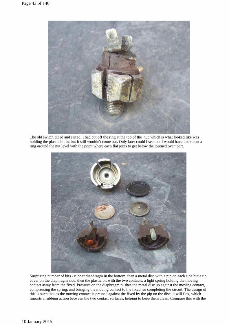
The old switch diced and sliced. I had cut off the ring at the top of the 'nut' which is what looked like was holding the plastic bit in, but it still wouldn't come out. Only later could I see that I would have had to cut a ring around the nut level with the point where each flat joins to get below the 'peened over' part.
Surprising number of bits - rubber diaphragm in the bottom, then a metal disc with a pip on each side but a tin cover on the diaphragm side, then the plastic bit with the two contacts, a light spring holding the moving contact away from the fixed. Pressure on the diaphragm pushes the metal disc up against the moving contact, compressing the spring, and bringing the moving contact to the fixed, so completing the circuit. The design of this is such that as the moving contact is pressed against the fixed by the pip on the disc, it will flex, which imparts a rubbing action between the two contact surfaces, helping to keep them clean. Compare this with the
Page 43 of 140
10 January 2015
simple 'bridge' connection on modern switches below.
Burnt and pitted contacts, hardly surprising it had failed, surprising it lasted so long!
As far as fluid contamination goes although the rubber diaphragm is probably squeezed pretty tightly between the body of the switch and the plastic part forming a seal, maybe silicone can squeeze through that, and maybe modern switches don't compress the diaphragm as tightly anyway, and maybe the contact material is just poorer. But these (a very old switch much before my time 21 years ago, and quite possibly original) look pretty flimsy anyway.
The 'new' switch, showing the position of the cut to open it up:
A different internal construction, from left to right: The metal body, the rubber diaphragm, the contact disc (no tin cup), the plastic body containing the two contacts and two springs this time, and the cut-off part of the metal body. The contacts are visibly different, being simply the ends of the pushed-through spades bent over, as compared to the domed-head rivets used to attach the original spades and contacts. Whereas the original
Page 44 of 140
10 January 2015
design was able to select a different, and more suitable material for the contact surfaces to the spades, the present design does not.
Only slight burning of the disc and contact on this switch compared to the severe burning of the original, but obviously enough to significantly affect operation, almost certainly because there is no rubbing action between the contacts as on the originals.
Brake-light Switches
The original hydraulically operated switch screwed into a brake line junction
Page 45 of 140
10 January 2015
The first mechanical switch used on rubber bumper RHD cars, and Mk2 North American spec.
The very short actuator pin (arrowed) on this swotch means it has to be quite precisely located for correct operation. Not far enough in the lights are on all the time, too far in and it restricts the brake pedal return, which can cause the brakes to jam on as the fluid heats up and expands.
Page 46 of 140
10 January 2015
The 77 and later RHD switch mounting bracket from Clausager. Why the switch isn't mounted here in this example is not known.
The 75 and later North American spec (and subsequently all LHD) switch mounted behind the pedal box, albeit a non-standard switch (Mikel Moor's 1978 MGB with 1964 Buick 300 V8)
Page 47 of 140
10 January 2015
Instrument Lighting
Showing the recessed push-button in the knob of the rheostat and also the two nuts on the threaded portion of the rheostat body.
Showing the push-button in the shaft and the recessed face of the hexagon in the knob which must go over the push-button when refitting.
Page 48 of 140
10 January 2015
General view of the rheostat showing the two spades for each terminal in a 'U' shape.
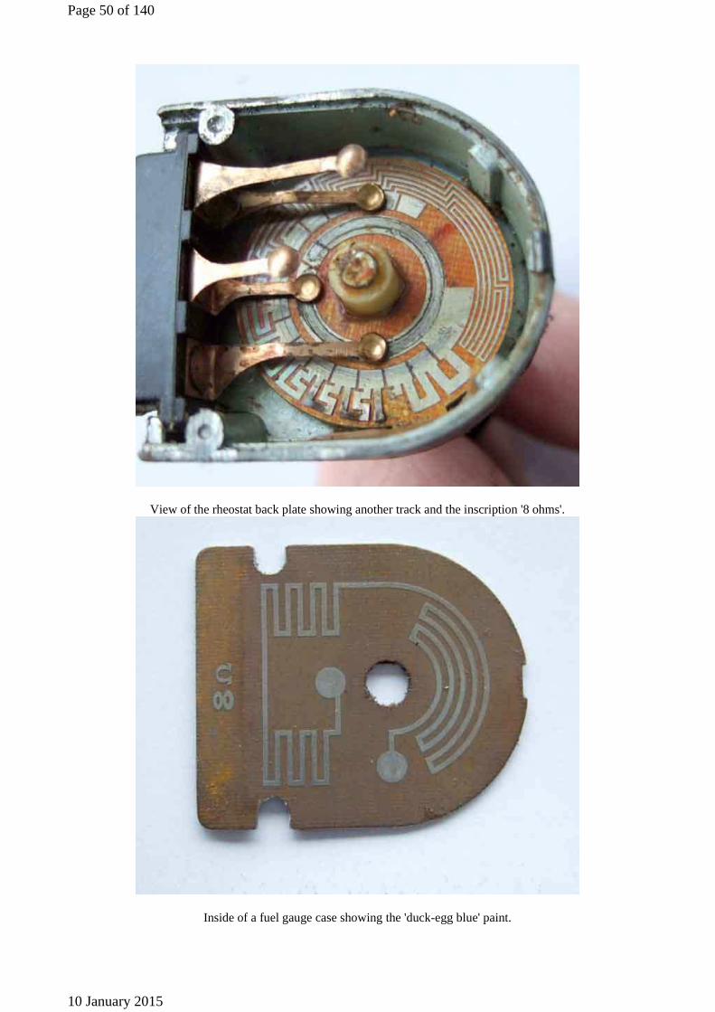
Internal view of the rheostat showing multiple printed circuit tracks of varying thickness and length and heat damage at the bottom. The track starts off in the bottom right-hand corner as short thick tracks to give low
resistance with high current carrying ability. As the printed circuit (attached to the control knob) is rotated anti-clockwise the tracks get longer to give more resistance and thinner as less current carrying capacity is required. This
is shown at near maximum resistance the last segment is not connected to anything to give a 'fully off' position.
Page 49 of 140
10 January 2015
View of the rheostat back plate showing another track and the inscription '8 ohms'.
Inside of a fuel gauge case showing the 'duck-egg blue' paint.
Page 50 of 140
10 January 2015
Showing the back of the fuel gauge face-plate relative to the case which has the same blue colour on the back of the upper part (carrying the 'SMITHS' and 'FUEL' markings) but matt white on the back of the main part the lower half of which carries the graduations. The bulb is situated at the bottom of the case and so mainly illuminates the white area of the face plate and the inside of the case. Light scatter then has to occur to get through the aperture at the top
of the face-plate which then has to scatter still further before it reaches the pointer and graduations.
Improving Instrument Lighting
A few years ago there was a recommendation from America to fit Radio Shack 7.5v bulbs, but given the running voltage on the car of 14.5v or so they were a bit like a firework - bright, but short-lived! Subsequently halogen lamps were recommended (again from America), giving significantly more light output. If they are significantly higher current items they could damage the rheostat when used en-masse, and if they are much higher heat output they could also affect
the instruments, switches etc. The LBCarco items are 5w for the small gauges and 10w for the speedo and tach, i.e. twice to four times the wattage of standard items (they also recommend a 3w item for what they describe as 'green film' gauges, possibly because the higher heat output of the higher wattage items damages these gauges (see heat comparisons below). I've measured the current drawn by a standard 2.2W, a standard 4w, and a halogen 6w (all available in Halfords) and the halogen current is pro-rata with the tungstens at 200mA for the 2.2W, 300mA for the
Page 51 of 140
10 January 2015
4w, and 500mA for the 6w. However a set of 5w and 10w items will be drawing more 3 times more current through the rheostat than the standard bulbs. I've only been able to find 4w standard and 6w halogen bulbs with bayonet fittings in the UK, not screw. Whilst the 4w is comparable in price to the standard 2.2w bulb the 6w halogen is about 5 times the price and the LBCarco items are 10 times the price of standard bulbs! However Tesco 12v halogen 5w and 10w capsule wire ended bulbs are about the same price as standard tungsten, and the wire ends could possibly be soldered into screw caps of old standard bulbs. The feature of halogen is that they are brighter than standard tungsten for a given current. Tungsten could be made this bright but they wouldn't last very long (like the Radio Shack items) as metal is evaporated off the filament more quickly, eventually causing burn-out. Halogen gas has the effect that when the bulb is switched off, the metal that has been evaporated off the filament migrates back to the filament again as it cools. Effectively this is like starting with a brand-new bulb each time you turn it on! The down side is that they do run much hotter for a given wattage: at 10C ambient the 2.2w runs at 30C, the 4w at 55C, and the halogen at a whopping 90C. As the bulb is at the bottom of the gauge (the fuel gauge at least) this may even contribute to higher than normal readings on both thermal gauges. Also halogen bulbs should not be handled with the fingers as oils will be deposited onto the surface which will form a burnt-on film reducing output, increasing heat and shortening life. Given that the 5w and 10w items are 2 and 4 times the output of the standard bulbs, maybe ordinary tungsten at that wattage (if available in the correct size and fitting) would be almost as effective run cooler, and be a lot cheaper.
Another alternative that cropped up on the MG Enthusiast BBS was an electro-luminescent ring which fitted inside the gauge. A link to a photo was posted, but without a 2nd gauge with standard illumination for comparison, hence there was no indication of how much brighter it actually was. Taking photos of lights is always problematic and the gauge numbers were quite dim. Someone posted that they were interested, 'but can you make the picture a bit brighter'! I don't know whether the request was genuine or tongue in cheek, but it certainly made me laugh.
Another option I'm following up is white LEDs. Very low current and heat, and the super-brights really are bright - forward facing anyway. This UltraLeds.co.uk site has loads of automotive LED bulbs, the instrument types at least being about twice the price of standard bulbs so not too bad,
but postage is a bit steep at nearly 4 quid for a single bulb and VAT is also extra. Note that LED replacements for external incandescent bulbs may not be legal in the UK, even though manufacturers are installing LED arrays in many cars these days which are legal, and I've seen one site that states that even LED instrument lights are not legal on UK public roads. I looked around at Maplins and bought a single oval high-brightness, wide-angle LED as an experiment. Whilst very white and bright side-by-side with the standard incandescent yellow glow it is actually quite small, and inserted into the gauge it gave hardly any illumination at all. It is also a fiddle to use as one has to add a 1k resistor to limit current, and a diode to prevent reverse connection, as well as soldering it all to a screw-base to fit the car.
Given that the commercially available items contain four to six LEDs and are cheaper than I can buy all the bits for it just isn't worth the bother, so I ordered two LED bulbs from UltraLeds (now NLA) - one wide-angle and the other standard. Not too badly priced at £3 for the standard and £3.50 for the wide-angle, but post and packing added another £3.50 making each bulb about the same as Halfords 6w halogen. You could get a lot more bulbs for the same £3.50 p&p, though. These include six LEDs, a dropper resistor, and a diode array (for screw-in bulbs, a single diode for wedge types as these can be inserted either way round) so they will work with either polarity without damage. They are rated at 5w, but whereas with the standard tungsten you can multiply running current (typically 220mA) by supply voltage to get the wattage stamped on the bulb base, LEDs take about 1/10th the current. So when (if) an LED supplier gives a wattage they are generally indicating the relative brightness, although some do give the correct figures i.e. a 3.3v, 340mA I have seen really is the claimed 1W, and is very bright indeed (but before you get too excited physically not suitable for instruments). In the fuel gauge the UltraLeds are whiter, but probably no more legible. In the tach they are significantly brighter making the instrument easier to read.
Will the dimmer work with LEDs? With all LEDs installed the dimmer won't function at all - other than in the fully 'off' position (next to the maximum brightness position) because of the much lower current with LEDs. With five incandescent (four gauges plus cigar lighter) of 220mA each that's about 1 amp. Say you want to reduce the voltage on the lamps to 3v to give maximum dimming, or one quarter of the voltage. At 1 amp and 12v the combined bulbs have a notional resistance of 12 ohms. With three parts of the voltage (9v) across the dimmer, and one part across the lamps (3v), a current of 250mA is implied, which is also flowing through the dimmer. To drop 9v at 250mA the dimmer must have a resistance of 36 ohms. With one tenth the current flowing through the LEDs, i.e. 100mA, a resistance of 120 ohms is implied. Insert 36 ohms i.e. the maximum resistance of the dimmer in series with that you get a total of 156 ohms, which reduces the current to 77mA. But that will drop only 2.8v across the dimmer, leaving 9v across the LEDs, and because of their voltage/brightness characteristic that will hardly dim them at all. You could try and mount a higher value variable resistor behind the visible parts, you could use the standard dimmer to control an electronic circuit that used pulse width modulation (switching them on and off very rapidly, reducing the length of the 'on' period and increasing the length of the 'off' period to dim them), or simply add a load resistor to increase the current through the dimmer which will drop more voltage. But is it even necessary? The dimmer has an
Page 52 of 140
10 January 2015
'off' function, and they are unlikely to be dazzling (unlike a Metro I was forced to hire once, couldn't find a dimmer or off switch, to had to prop the hire documents in front of the instruments ...).
Update February 2011: Ultraleds doesn't seem to have these anymore, but a different design from eBay was mentioned on the MG Enthusiasts BB. Available in various colours and two angles, I got a couple of white standard angle based on the results with Ultraleds type but the results were disappointing. Apart from the different colour there was no difference in legibility, in fact the LEDs could be very slightly worse. Probably a factor of the single-element design of these compared to the multi-element of the Ultraleds. There are green versions with a luminosity of 12,000 as opposed to the 8,400 of the white, these may be a bit better. I can't recommend them, but if you want to try them
there is a selection from various 'shops' here. In the fuel gauge at least the wide-angle may work better than the standard.
Update August 2011: As one of his periodical sagas Herb Adler sent details on how he uprated his instrument lighting to use LEDs - see here and scroll down a bit. He used flexible 12v LED strip that can be cut into 50 or 100mm sections, each powered independently from 12v. The comparative photo he includes - although blurry - shows a remarkable difference in brightness and is probably the first time an MGB has warranted a dimmer. But of course the standard dimmer won't dim LEDs, so he also includes a section on using a potentiometer and resistor as an effective dimmer, glued onto the back of the rheostat mounting plate so the dash-front appearance is standard. There are a number of suppliers of this LED strip, found through Google, one of the cheapest being £13 per metre, but a lot of work to install.
Update September 2011: Yet another option, Goffy's LD18MES - single-element but large surface-area, 180 degree angle, direct-replacement. About the same improvement as the no longer available UltraLED type, but again quite pricey for both bulb and P&P.
February 2013: Still searching. As time goes by and the years mount, as well as infrequent driving of either of the MGBs at night blunting familiarity with what the needle angles mean, improved brightness is probably becoming more necessary for me now. Whilst investigating DRLs I came across a 5-
element LED with a T10/wedge fitting for the V8 pilot lights (i.e. parking light fitted to the headlight reflector) as a possible option, very cheap at £2.20 for two. They proved pretty useless for that application, if anything they gave a smaller splodge (a technical term) of albeit blue/white light compared to the standard incandescent, but I thought it was worth trying them in the instruments. The wedge pilot light holder is just too small to fit the hole for the 'claw'-type holders used in the larger chrome bumper speedo and tach, but I held it in position for a quick test and it gave by far the best results of anything I've tried so far. This is almost certainly due to the four radial elements being inside the case and more effective than any of the forward facing ones I have tried, even those with supposedly a 180 degree beam. I couldn't find any bulbs of this type with an MES (medium Edison screw, which is what all eight of my instrument bulbs are) fitting, but I found an old 'claw' fitting and was able to cut it down to act as an adapter between the gauge and the wedge holder (as a proof of concept, eventually this holder would have to go back in the headlight).
There are however 'claw' BA9 holders and BA9 versions of this bulb, so changing the holder is another option. I got a couple of claw BA9 holders from Stoneleigh although the claws were a different shape, and disappointingly they were slightly too small to fit the roadster gauges (there seem to be a plethora of slightly different sizes of both these and the wedge holders). In the meantime someone sent me what they thought I needed, but although they had the correct claw
they were MES and not BA9. However by cutting the claw flange off those, and the incorrect claws off the other, I soldered the two parts together to make the correct holder. Made up two of these and shipped them off to Michael Beswick who has also been investigating DRLs and better instrument lights with me. Michael sent me some odd wedge holders, and I had another one, and out of those of those I made up a couple that fitted the roadster gauges with a bit of tweaking.
The ancillary gauges and the smaller V8 and rubber bumper tach and speedo have 12mm tubes on the backs for cylindrical bulb holders. As a quick test even pushing the bulb in to a fuel gauge as far as it would go the radial elements are shrouded by the cylinder and the results were no better than anything else I had tried. On the dual oil/temp gauge one of the Bourdon tubes goes right past the inner end of the cylinder, so this type of bulb is too long for the ancillary gauges at least.
But I also picked up a couple of tubular BA9 holders as a result of Stoneleigh, and these were slightly too small as well i.e. there are several different sizes of this type of holder! However the tubes on the back of the gauges have slits in them so they can be 'adjusted' to suit. The five-element BA9s are superb in the V8 speedo and tach, just like
Page 53 of 140
10 January 2015
the wedge versions in the roadster, so it is worth doing the mod. Unfortunately the holders on the V8 do not have bullet connections, but come out of the harness directly, so I have to cut the existing holders off and solder and heat-shrink the new ones on, with is something I usually try and avoid having to do. I then notice that the speedo isn't as bright initially, but goes brighter if I wiggle the holder, and then I notice the speedo needle is moving! I realise this longer bulb and holder are going further into the speedo and is fouling the innards. Fortunately the holder is such that I can modify it to hold the bulb about 1/2" further back, where it is as bright as the tach and no interference with the needle. It should be noted that 77 and later 'green film' gauges have a bubble of green plastic over the end of the tube inside the gauges, which will stop longer bulbs going in further than the originals. Which as well as shrouding the radial elements on these bulbs may mean the holder doesn't go into the gauge far enough to stop it falling out with the vibration encountered in normal use.
I then wonder whether this is going to be a problem on the roadster as well. Remove the wedge holder ... no bulb. Search around behind the dash, no bulb, then realise it must have come out of the holder and dropped inside. By this time I'm quite adept at the 'James Herriot' position reaching over the tach to get to the speedo, and in through the dash with the fresh air vents removed, get the speedo out and can fiddle the bulb out of the hole, rather than having to open it up. This holder
and bulb are about 1/4" longer than the claw and tungsten, which is a bit of a concern. Then I realise the collar on the base of the LED bulb is just too wide to go down inside the wedge holder as it should, but a 5/32" drill opens out the holder, and the bulbs goes in another 1/8" or more. So now not only is the bulb not in the speedo so far, it's held more securely in the holder as well, and I decide to do the tach as well even though there is nothing moving around in the back of the tach case like there is in the speedo.
That leaves the ancillary gauges. I've done all the testing of different bulbs in the fuel gauge as that is so easy to get to, and none of them have made it any more legible then the original bulbs. With the fresh-air vents out to get to the speedos I put my best MES (screw-in) LEDs in those - and the results are as good as the large gauges! The fuel must be so poor because the holder is at the bottom so the light has to go up to the top before it can come down onto the face, whereas in the oil/temp it is at the top to start with. So that just leaves the fuel, I'll have to try painting the inside (spare gauge first - when I can find it again) and see how that goes. But arguably that is the
least important, and I can still see the angle of the needle. It would be nice to get that as good as the others though.
Well I did find my old fuel gauge, and though a combination of factors realised why that doesn't improve with the LED bulbs like the others do. The other three are 'edge-illuminated', which means light come through a gap all the way round between the face-plate and the case, whereas on the fuel gauge you are relying on the scatter that comes through the hole in the upper rear part of the face-plate, when the bulb is at the bottom. I experimented with a number of possibilities
including making it edge illuminated like the dual gauge and although I ended up with a fuel gauge as bright as the others, I'm wondering if it is worth the effort. Probably not, given the fuel level changes at a predictable rate, is not something you need to keep an eye on like oil pressure or temperature, and there is enough light anyway to see the angle of the pointer.
I was convinced there must be MES i.e. standard screw fitting versions of these bulbs, so despite all the work above had kept looking from time to time. And while Googling '12v MES LED' I realised that an alternative description was 'E10'. Googling that instead of MES got a couple of hits for the correct type of bulb, but it was factories touting for bulk purchases and wholesalers with bundles of 100 units. But then I noticed they all had the same description 'E10 5 5050 SMD
LED' and Googling that led me to a pair for £2 and free shipping from China! Michael now has some of those on order, and we will see if there are any issues with those projecting too far into the gauges. Still waiting after the maximum 31 days delivery and no response to emails from the seller. There are a flurry of recent bad reviews on the site about late and non-delivery and no response from the seller, so link deleted. Eventually they arrived after about six weeks. In the meantime I ordered two from another supplier in China, £4 for two so double the price but still cheap, and they arrived in 14 days. Obviously the extra price is for go-faster lettuce for the snail.
These are a direct replacement for the standard tungsten bulbs, so no fiddling around with alternative holders, and they give the best improvement yet in the fuel gauge.
Some have said they are not keen on the bluish tinge that comes from 'white' LEDs in the duck-egg blue painted cans, 'warm white' give a colour closer to the original incandescent, but with the brightness of the white.
Page 54 of 140
10 January 2015
LED Instrument Lighting
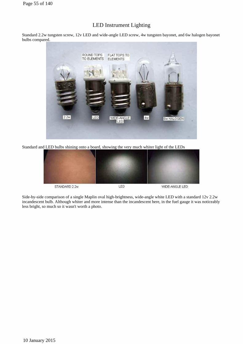
Standard 2.2w tungsten screw, 12v LED and wide-angle LED screw, 4w tungsten bayonet, and 6w halogen bayonet bulbs compared.
Standard and LED bulbs shining onto a board, showing the very much whiter light of the LEDs
Side-by-side comparison of a single Maplin oval high-brightness, wide-angle white LED with a standard 12v 2.2w incandescent bulb. Although whiter and more intense than the incandescent here, in the fuel gauge it was noticeably less bright, so much so it wasn't worth a photo.
Page 55 of 140
10 January 2015
The following images are as I see them when driving and so are not intended to be bright enough to clearly read them, they just show the comparison between standard and Ultraleds LED bulbs.
Fuel gauge with incandescent (left), standard LED (centre) and wide-angle LED (right) bulbs. Very little difference in legibility between the three, although the LED bulbs give a whiter glow.
Tach with incandescent (left), standard LED (centre) and wide-angle LED (right) bulbs. Both LEDs give a significant improvement in legibility over the incandescent, with the standard LED again being noticeably better than the wide-angle. To me the whiter light of the LEDs also gives a more attractive appearance over the yellow of the incandescent.
eBay LEDs: Single element with a lens effect. Top image has LED in the tach and standard in the fuel gauge, lower image the other way round. Apart from the colour I'd say there was little difference in brightness and legibility, if anything the LEDs are not quite as good.
Page 56 of 140
10 January 2015
Goffy's MES single-element but large surface-area, 180-degree angle, direct-replacement LEDs. Very bright, but despite their 180 degree radiation only very similar results to the no longer available UltraLED multi-element type which are much more focused, even the wide-angle unit. This picture is a true comparison of an original with a LED as speedo and tach were photographed together, just moved closer together in Photoshop for convenience. Also like the UltraLED there is no increase in visibility in the ancillary instruments, just a change in hue, and quite expensive.
Five-element T10 wedge from Amazon, very cheap at £2.20 and free postage for a pair (these are often £5 each plus postage). However they are not, of course, either Xenon or HID as claimed, and there are also a number of negative comments about the quality of these. All I can say is that they fitted and worked out of the box, although they did take
Page 57 of 140
10 January 2015
six days to arrive, but there are a lot of other suppliers of this configuration out there. Not particularly bright, but the four radial elements plus the forward facing give a much better spread of light in use than those that only face forwards. This picture is of one of them in the roadster tach, with a standard bulb in the speedo for comparison. No Photoshop jiggery-pokery but significantly brighter and more legible than anything else I have tried. There is a 10 element version, however that is longer, so may foul the gauge innards.
The chrome bumper speedo and tach have 16.5mm 'claw'-type holders, but the hole is too large for the T10/wedge holder used for the V8 headlamp pilots. So I took an old 'claw'-type holder, cut off everything behind the claw and flange, and carefully filed out the hole until the wedge holder was a snug fit to give me an adapter. That got me a secure mounting, but it is a bit of a fiddle, and not everyone will want to buy new claw fittings and chop them up! However there are BA9/T11 bayonet versions of these bulbs and bayonet 'claw' holders that should fit these larger gauges. That still means replacing the holders, so you pays your money
and you takes your choice.
Correct claw flange cut off an MES holder, and soldered to a BA9 holder that had the incorrect claws cut off.
Page 58 of 140
10 January 2015
BA9 holder and bulb. Initially projected into the V8 speedo too far and fouled the innards ...
... but soldering a sleeve around the narrower part of the holder means it can be held securely about 1/2" further out.
Page 59 of 140
10 January 2015
T10 wedge holder and bulb. Didn't seem to be fouling the roadster speedo innards but the bulb wasn't held very securely and had dropped inside once already. The white disc at the base of the bulb was just too large to fit inside the holder ...
... but reaming out the holder a few thou was all that was necessary.
Page 60 of 140
10 January 2015
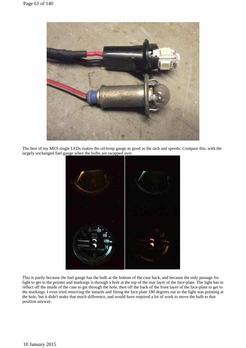
The best of my MES single LEDs makes the oil/temp gauge as good as the tach and speedo. Compare this, with the largely unchanged fuel gauge when the bulbs are swapped over.
This is partly because the fuel gauge has the bulb at the bottom of the case back, and because the only passage for light to get to the pointer and markings is through a hole at the top of the rear layer of the face-plate. The light has to reflect off the inside of the case to get through the hole, then off the back of the front layer of the face-plate to get to the markings. I even tried removing the innards and fitting the face plate 180 degrees out so the light was pointing at the hole, but it didn't make that much difference, and would have required a lot of work to move the bulb to that position anyway.
Page 61 of 140
10 January 2015
This is despite the 'sockets' for the bulb holders being that much longer on oil/temp gauges (top) than the fuel gauge (bottom) ...
... which means that the bulb for the fuel gauge is effectively inside the case whereas on the oil/temp gauges it is back inside the tube.
Page 62 of 140
10 January 2015
Then I realised the main reason the other three gauges are so much better with LEDs is that they are 'edge illuminated'. By that I mean that there are gaps between the outer perimeter of the face-plate and the inside of the case, so light escapes almost directly, and all the way round. This old temp gauge shows what I mean about edge-illuminated: There are slots cut into the edge of the face plate, covered by a translucent plastic strip to diffuse what comes through. The pale blue here is the inside of the case seen through the slots in the face-plate, translucent strip removed.
Apart from those slots the physical design of the face plates is the same - fuel face-plate on the top, old temp gauge face-plate below.
Page 63 of 140
10 January 2015
So can I cut slots in the fuel gauge? It's only thin brass to will distort easily, and a drill might tear it to shreds. But I have a one-hole punch ...
... and with the spring removed that is the perfect size and angle to punch a series of holes.
Page 64 of 140
10 January 2015
Filch the translucent strip from the temp gauge, and reassemble.
Now, at long last, I have a fuel gauge that is as bright as the others.
But this is only an old gauge, I came to the conclusion it probably wasn't worth the effort of modifying the two in
Page 65 of 140
10 January 2015
the cars.
When I eventually get an MES version of the five-element LEDs ...
The improvement is the best yet - albeit not quite as legible as the other instruments.
Vee's dual gauge failed on the way back from Stockport air show - very disconcerting not being able to see the oil pressure and temperature! I think it was one of the (NLA) UltraLED ones with the five forward-facing elements. I still had the other one (one was 'standard' and the other wide-angle) so put that in which gave quite a good light in this gauge, but ordered a couple of the MES 5050 type which give a good light in all the gauges. Previously I'd bought 'white', but this time ordered 'warm white' as a comparison. UltraLED above, warm white below. MES 5050 slightly brighter, although I do prefer the bluish tinge of the 'white' in the speedo (and other gauges) which comes from the duck-egg blue paint inside the gauges.
Page 66 of 140
10 January 2015
Dash Lighting
LED strip lights
Cut at the copper strips, three elements minimum
Page 67 of 140
10 January 2015
Connector block ...
... but heat-shrink is just as effective and less obtrusive
1/8" gap on my roadster ...
Page 68 of 140
10 January 2015
... the V8 has beading in this gap, but it can be lifted out of the way.
Fitted
Page 69 of 140
10 January 2015
Amost invisible when driving
Page 70 of 140
10 January 2015
Way too bright at a full 12v
Brightness reduced with a resistor. The reflection from the dash panel and tops of the fres-air vents looks like it might be distracting compared to the illumination of the switches and controls, but in practice it isn't.
Headlamp Flasher Hover over a wire to confirm the colour
Page 71 of 140
10 January 2015
Note: Column-mounted dip-switch/headlamp flasher shown. For the earlier floor-mounted dip-switch the blue/white from the column flasher switch joins the rest of the circuit by the floor-mounted switch.
Reversing Lights Hover over a wire to confirm the colour
Note 1: Late UK cars seem to have a subdivision of the green circuit with its own in-line 35 amp fuse supplied by the white/brown (ignition relay) circuit feeding things like heated rear window, turn signals, heater fan and tach, which leaves the original green circuit fuse (2nd one up in the four-way fuse block) feeding things like reverse lights, stop lights, washers, wipers, and circuits associated with the seat belt warning lamp and time delay buzzer. Note 2: The bullets for the reversing light grounds also contain the wired grounds for rubber bumper (and 1974 North American with split rear bumper) number plate lights.
Location of the reverse light switch on a 3-synch gearbox ...
Page 72 of 140
10 January 2015
... and a 4-synch UK (74.5 to 76) gearbox:
Showing the large access panel on top of the 3-sync tunnel (left), as opposed to the small one on the 4-sync. This should be enough to get at both the OD and reverse light switches on the 3-synch, whereas on the 4-synch the rear crossmember and back of the gearbox has to be dropped as well for access to the OD switch at least. Image from Moss Europe Incidentally the 4-synch removable panel is shown the wrong way round by Moss, the hole for the gear lever is towards the rear, not towards the front as here.
Page 73 of 140
10 January 2015
Interior Lights, with 'lights on' warning Hover over a wire to confirm the colour
Note: It's advisable to use a diode in both configurations or you could get a continuous current drain through the courtesy light, buzzer and parking lights, when the lights are off and the doors closed. Polarity of buzzer (if polarity sensitive) and diodes are shown for negative ground cars, for positive they should be reversed.
Inset 1: This avoids cutting factory wiring but causes both passenger and drivers doors and the courtesy light manual switch to sound the 'lights on' warning. NB. Miles Bannister has pointed out that the original schematic for Inset 1 didn't include the diode and this would result in the drain referred to above. My (weak) defence is that I have never used Inset 1, I only included it for those people that didn't want to cut a factory wire. The diode solves the problem, thanks Miles. If the diode is accidentally reversed the buzzer won't work, but you will get the drain referred to. Updated September 2010: Note that polarity sensitive buzzers may block this reverse current drain, you would have to test your buzzer with an ammeter. Measure the current in the normal direction i.e. buzzer sounding, then measure again with the buzzer connections reversed (which shouldn't harm the buzzer). If there is no current flow when connected in the reverse direction then you don't need the diode in this configuration.
Inset 2: This arrangement results in only the drivers door sounding the buzzer. The diode prevents current flowing through the buzzer to the ground from the passenger door switch, and it is this that causes the buzzer to ignore the passenger door. It must be inserted between the drivers door switch and the branch to the courtesy light. To avoid cutting into wiring you can make up a diode with two bullets and an additional 2-way connector and insert it where the wire from the drivers door switch joins the wires from the passenger door switch and harness at the 4-way connector behind the centre console. NB. Darren Lewis has just (September 2004) advised me that originally (and
Page 74 of 140
10 January 2015
for the past four years!) the diode was shown connected the wrong way round for the negative ground car shown. It is now correct. Thanks Darren. If the diode is accidentally reversed the courtesy light will only respond to the passenger door (and the manual switch), not the drivers door. Note this diode is required irrespective of whether your buzzer blocks the reverse drain current.
Diodes showing how the markings relate to the schematic symbol, i.e. the marked end (red blob, thick silver band) denotes the pointed end of the 'arrow' symbol, and the direction of the arrow indicates the direction of conventional current flow i.e. from +ve to -ve. Note the one on the left is a Lucas (yes, that Lucas) diode, the other is the type you are more likely to find these days:
'Lights on' Warning with Seat-belt Buzzer - North American spec cars
In all cases add the relay with connections to the purple/pink and red/green circuits as shown. The relay simulates the key being left in when you open the door, i.e. sounds the buzzer, but from the lights being left on instead. The key-in function is unaffected, if either the lights are on or the key is in when the drivers door is opened, the buzzer will sound. 1971-73 driver and passenger seat-belt warning system
1973-75 driver and passenger seat-belt warning system with starter interlock, and 75-80 driver only systems.
Page 75 of 140
10 January 2015
Door Switches
The original type of door switch, showing the typical corrosion that develops. Note it is only round the contact area (although this is possibly the effect of electricity in the junction accelerating the corrosion at this point)!
However if the contact is only intermittent and not failed completely it may be possible to recover. With the switch removed grasp the mounting ears in one hand and the socket for the wiring bullet in the other, and twist back and fore while pressing the two parts together to get a nice shiny contact surface as shown here.
Page 76 of 140
10 January 2015
Once you have a reliable electrical connection push the plunger to open the switch and daub Vaseline or grease between the two open halves of the contact, then slide on a suitable diameter sleeve. The fixed part is conveniently of a slightly larger diameter than the moving part, so choose your sleeving correctly and it will stay on the fixed part while allowing the moving part to slide in and out. If fitting a new switch then it makes sense to do the Vaseline/grease and sleeve bit from the word 'go'.
The non-standard switch, which was the only type available some years ago. This is actually better for the door as the plastic plunger is less likely to scratch through the paint, but the cylinder behind the mounting ears is a slightly larger diameter than the original so the hole had to be opened up. To do this with a drill the wire has to be pushed back out of the way (make sure you don't lose it (I didn't)), and touch up the edges with paint afterwards.
Page 77 of 140
10 January 2015
When my son bought one of his classic BMWs the owner advised him there was a problem with the courtesy lights flattening the battery as they were on all the time, so he had disconnected them. A quick check indicated a possible wiring short to earth somewhere between the two doors and the boot which would have been a pain to track down. However my son idly pushed the passenger door switch in with his finger while the door was open one day, and the lights went out! He looked at the face of the door frame that the switch bears on when the door is closed, and discovered there is a hole in that position that should have a plastic plug, so the switch doesn't scratch the paint, and the plug was missing that side!
Fog & Spot Lights, Factory-fitted, 62-70 Hover over a wire to confirm the colour
Fog & Spot Lights, Factory-fitted, 70 on Hover over a wire to confirm the colour
Page 78 of 140
10 January 2015
Fog & Spot Lights, After-market Hover over a wire to confirm the colour
Note: The in-line fuses prevent faults in added wiring damaging the original harness, they should be connected as close as possible to where the red and brown are picked up. More recent systems tend to switch the ground to the lights, which means they are permanently connected to a fused 12v supply. This is no safer than as shown above but does require extra wiring as both 12v and ground wiring is required to the lamps, relays and illuminated switches.
Aftermarket Fog/Spot Lights
Personally I think rectangular lamps in this location suit the lines of the rubber bumper cars well. For chrome
Page 79 of 140
10 January 2015
bumper cars with them mounted in front of the grille, round lights matching the headlights would probably be preferable.
The additional lights are bolted vertically upwards into an L-shaped bracket. The bracket turns upwards in front of the valance and is held with one or two valance bolts. Whilst I have fitted new lamps to the brackets many years ago, the brackets were fitted by a PO and so I'm not certain if the holes and bolts were pre-existing for the valance or added by the PO.
Page 80 of 140
10 January 2015
"Key In" Warning North America 1970-on
Radio installation
Installed ...
... removed (the surround is cut from an old Metro blanking plate to cover up a mass of holes a PO had drilled around the edge of the opening)
Page 81 of 140
10 January 2015
And the modified blanking plate ...
... installed.
Page 82 of 140
10 January 2015
CD player with cassette adapter
MP3 'jukebox'
Page 83 of 140
10 January 2015
77 (America) and 78 (UK) factory speaker cable routing, showing the grommet in the panel between door space and cabin ...
... and in the end of the door casing. I've used similar routing for the central locking in my 75 V8. This had the holes in the door casing already, with a sealing grommet, but I fed the cable through the hinge as I didn't want to drill a
visible hole, not knowing this routing at the time.
Page 84 of 140
10 January 2015
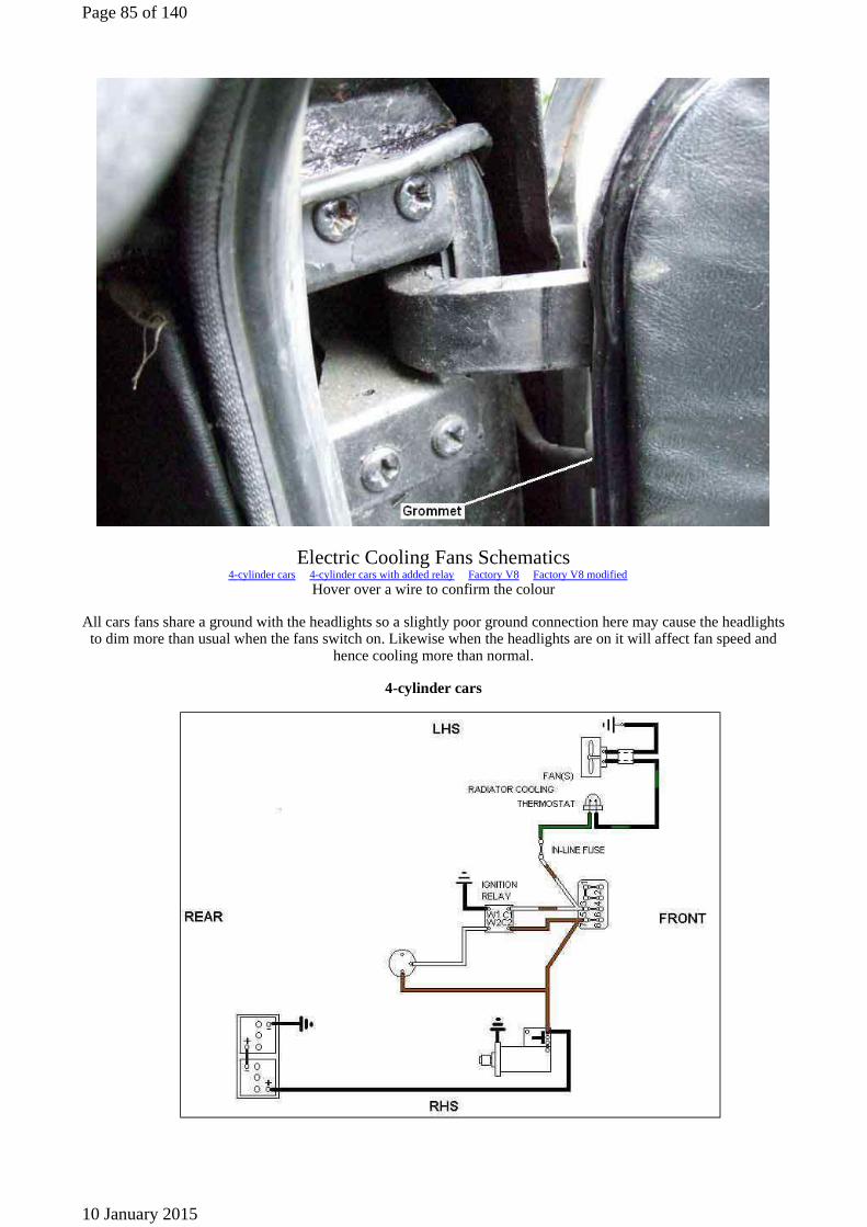
Electric Cooling Fans Schematics 4-cylinder cars 4-cylinder cars with added relay Factory V8 Factory V8 modified
Hover over a wire to confirm the colour
All cars fans share a ground with the headlights so a slightly poor ground connection here may cause the headlights to dim more than usual when the fans switch on. Likewise when the headlights are on it will affect fan speed and
hence cooling more than normal.
4-cylinder cars
Page 85 of 140
10 January 2015
Notes: 1: North American cars had two fans connected in parallel other markets only have a single fan.
2: All 4-cylinder cars have an in-line fuse in the fan circuit. This fuse is fed from the white/brown (ignition relay but see below) circuit then feeds the thermostatic switch with a green wire. Be aware that this green wire
is nothing to do with the main green circuit that is fused from the 2nd fuse up in the 4-way fuse block. 3: It seems that early cars with electric fans may have had a fan relay before they got an ignition relay and
when they got the ignition relay the fan relay was deleted. The Parts Catalogue shows a 3-terminal relay the same as for the V8s but in order to use this the sensor switch would have to be wired differnetly probably he
same as for the V8s. 4: Some owners have moved the white/brown wire for the fans from its usual position on the 4-way fuse block
to a spare brown spade. This results in the fans continuing to run when the ignition has been turned off or indeed starting to run after you have left the car. Nothing earth-shattering in doing so - except that a fault
could cause the fans to flatten the battery or in the worst case start a harness fire.
4-cylinder cars with added relay
Notes: 1. In this circuit the fan wire is moved from the thermo switch contact to a relay contact. When the thermo
switch closes it extends 12v from the green through to the relay which operates to a ground. The green on the thermo switch contact is extended to the other relay contact which when it closes powers the fans. Thus the
same green feed is used to power both the relay and the fans but the thermo switch only carries the light current of the relay the relay carries the heavy current of the fans.
2. You should not need to add a relay to 4-cylinder cars with standard fans even two as the standard switch seems more than man enough for the job. However if replacement radiator switches fail quickly they may like
replacement brake light switches be of poorer quality than the originals in which case a relay may be beneficial.
3. The relay contact number given are for current after-market relays. If using a standard Lucas relay use W1 for 85 W2 for 86 C1 for 30 and C2 for 87.
Factory V8
Page 86 of 140
10 January 2015
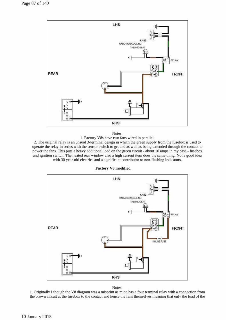
Notes: 1. Factory V8s have two fans wired in parallel.
2. The original relay is an unsual 3-terminal design in which the green supply from the fusebox is used to operate the relay in series with the sensor switch to ground as well as being extended through the contact to power the fans. This puts a heavy additional load on the green circuit - about 10 amps in my case - fusebox and ignition switch. The heated rear window also a high current item does the same thing. Not a good idea
with 30 year-old electrics and a significant contributor to non-flashing indicators.
Factory V8 modified
Notes: 1. Originally I though the V8 diagram was a misprint as mine has a four terminal relay with a connection from the brown circuit at the fusebox to the contact and hence the fans themselves meaning that only the load of the
Page 87 of 140
10 January 2015
relay winding is on the green circuit. A useful modification but it should really be fused for safety either as shown with an in-line fuse in the wire to the brown circuit at the fusebox or an aftermarket fused relay.
2. Even with this brown feed instead of the green there is significant volt-drop in the fan grounds which share a relatively small-gauge wire with each other and the headlights right back to a grounding point by the
fusebox. I provided an additional heavy gauge ground connection to a lug under one of the mounting bolts to the bonnet slam-panel for each motor. As my alternator has a spare large output spade and a spare input spade
on the relay I provided a heavy gauge brown wire between them to increase current still further. These changes supplied an extra 25% or so voltage to the motors which gives a very noticeable increase in fan speed and hence cooling. In this case you either need an in-line fuse in each brown feed join the two browns together and then via a single in-line fuse to the relay or a single in-line fuse from the relay contact to the black/green
fan wire. 3. Thanks to Graham Cornford for pointing out the error in the relay terminal naming. 4. If using a modern
relay the terminal numbering would be W1 = 85 or 86, W2 = 86 or 85, C1 = 87, C2 = 30.
Relay Types
A general view of a typical 6RA 4 terminal, 4 spade type
Four terminals but five spades. The double spade on terminal C1 offers a convenient branching point for a 12v supply wire to another circuit.
Page 88 of 140
10 January 2015
An alternative 4 terminal, 4 spade but with W2 in a different position and a C3 instead of a C1. This is a relay with a normally closed contact.
Five terminals and five spades, this has a 'changeover' contact i.e. when the relay opens it switches a common contact (C2) from a normally closed contact (C3) to a normally open contact (C1).
Page 89 of 140
10 January 2015
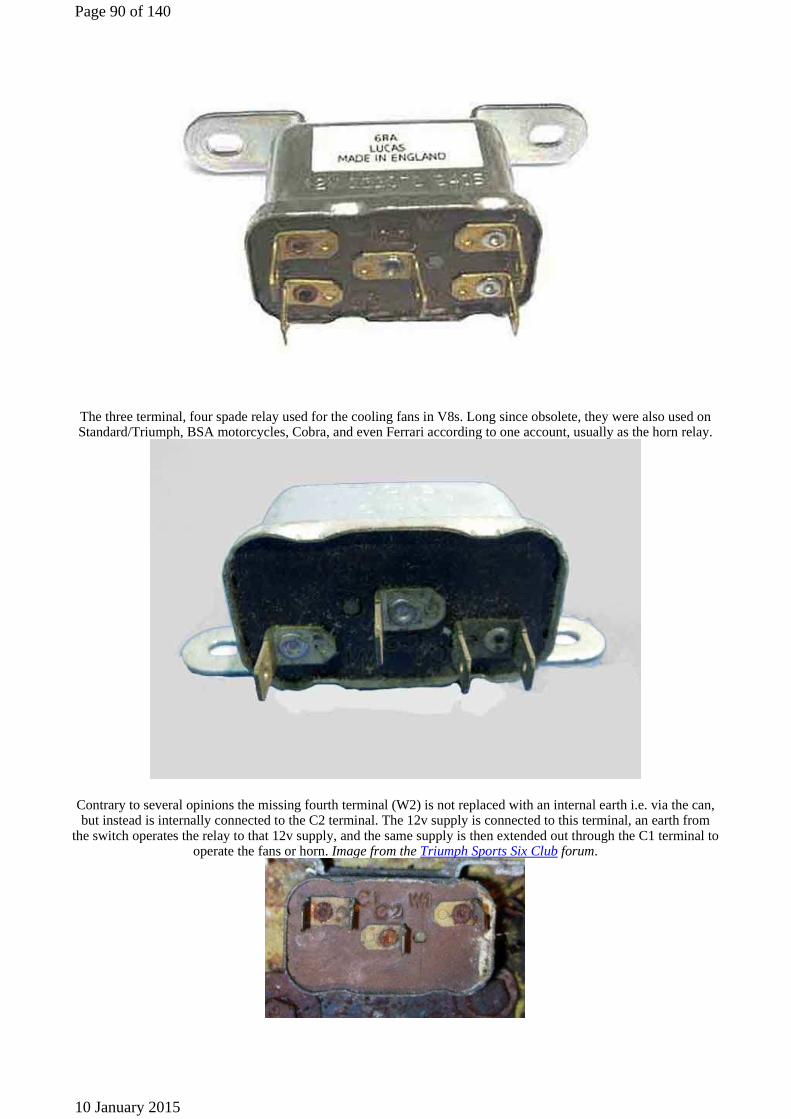
The three terminal, four spade relay used for the cooling fans in V8s. Long since obsolete, they were also used on Standard/Triumph, BSA motorcycles, Cobra, and even Ferrari according to one account, usually as the horn relay.
Contrary to several opinions the missing fourth terminal (W2) is not replaced with an internal earth i.e. via the can, but instead is internally connected to the C2 terminal. The 12v supply is connected to this terminal, an earth from
the switch operates the relay to that 12v supply, and the same supply is then extended out through the C1 terminal to operate the fans or horn. Image from the Triumph Sports Six Club forum.
Page 90 of 140
10 January 2015
Cylindrical Lucas relays used on later MGBs, designated 26RA, SRB402.
Took this off a friends car as although it was clicking as the ignition was turned off it's output was permanently energised, which had flattened the battery. Opened up (never could resist) to find one of the coil cheeks partly
broken away, which had worked itself round to the back of the armature, holding the contacts closed all the time. For a start it must have been sculling around in there for ages before getting into that position, and I'm amazed the gap was big enough for it to slide in, yet small enough to keep the contacts closed! You couldn't engineer it to do
that!
Cube-type Lucas 28RA relays also can be found on late MGBs, identical to current (pun not intended) after-market relays.
Page 91 of 140
10 January 2015
Terminal arrangement, pin 30 is usually adjacent to the mounting bracket
Internal circuitry of standard relays. Note that with S2 and S6 single diode protection the power supply to the winding must be connected the right way round or it will blow the diode, +ve must be connected to 86 and -ve to
85. Resistor protection isn't polarity sensitive, but doesn't give as much protection to the operating circuitry as diode protection.
Page 92 of 140
10 January 2015
Internal circuitry of power relays. S1 has a tungsten contact that closes first and opens last, and a lower resistance contact which closes last and opens first. The tungsten contact protects the lower resistance contact against the back
emf and high current from large inductive loads. S2 has double diode protection, the series diode protecting the parallel diode from damage through reverse connection, if reverse connected the relay simply won't operate. As
before +ve is connected to 86 and -ve to 85.
Horns Hover over a wire to confirm the colour
2-wire Horns (pre-77)
1-wire Horns (77-on)
Page 93 of 140
10 January 2015
2-wire Horn Relay
Sealed Wiring Junctions
Typical sealed junction, in this case in the red/white instrument illumination circuit
Brass 'staple' crimped round the wires and soldered ...
Page 94 of 140
10 January 2015
... with a heat-shrink end-cap plus a length of standard heat-shrink tubing over the junction
Seat Belt Warning North America 1972-73
Page 95 of 140
10 January 2015
North America 1974
North America 1975-on
Page 96 of 140
10 January 2015
UK 1977-on
Inertia Starter (remote solenoid, to 67) Hover over a wire to confirm the colour
Page 97 of 140
10 January 2015
Pre-engaged Starter (attached solenoid), 12v Coil (chrome bumper 68-on, not V8) Hover over a wire to confirm the colour
Note 1: 1968 and 1969 cars had the pre-engaged starter but no starter relay, the White/Red went direct to the solenoid.
Note 2: 1973 and 1974 North American cars with the Sequential Seat-belt System (aka 'bum detector') have the white/red connected to pin 1 of the control unit and a Yellow/Pink from pin 3 of the control unit to the starter relay.
Pre-engaged Starter (attached solenoid), 6v Coil (rubber bumper and all V8) Hover over a wire to confirm the colour
Page 98 of 140
10 January 2015
Note 1: Factory V8s have the wire from the starter solenoid to the coil in white/light-blue, the wire from the harness ballast to the coil is still in white/light-green.
Note 2: I've seen round black relays on a 1980 UK model with ISO terminal numbering as follows:
Note 3: On 1977 and later models with an ignition relay the wire from the relay to the solenoid may have reverted to white/red, i.e. the same as from the ignition switch to the relay albeit thicker, as white with a brown tracer was used
for the ignition circuits. On the other hand it may have become brown with a white tracer, diagrams differ.
Note 4: Also on 77 and later models the starter is used to test-illuminate the brake-balance and 'handbrake on' warning light via a diode. If this diode goes short-circuit it can cause the starter to crank continuously unless the
handbrake is released.
Note 5: At some time the white/brown from the starter relay to the solenoid changed to white/red, albeit in a heavier gauge than the white/red from the ignition switch to the relay.
Pre-engaged Starter Replaces Inertia
Wire colour Original numberingISO numbering
White/red from ignition switchW1 85
Black ground W2 86
Brown 12v supply C1 30
White/brown to starter solenoidC2 87
Page 99 of 140
10 January 2015
Solenoid Contacts
4-Cylinder pre-engaged: Earlier M418G pre-engaged starter on 18Gx engines: A - battery cable stud and large 12v spade. B - standard-sized
solenoid operate spade.
Later 2M100 pre-engaged starter on 18V engines, V8 starter is similar: A - battery cable stud. B - large 12v spade.
Page 100 of 140
10 January 2015
C - standard-sized solenoid operate spade. D - small bypass or 'coil boost' spade.
V8: A copper bar bridges the two stud contacts A and B when the solenoid operates, but the coil boost contact (arrowed)
is bent back ...
... so that the copper bar misses it altogether, so it has obviously never worked on this starter that I fitted in December 1999 as a newly rebuilt item.
Page 101 of 140
10 January 2015
The coil boost contact is straightened and positioned so that the copper bar touches it and pushes it down just before it reaches the two studs.
Pre-engaged Starter Solenoid
The solenoid has two windings - the pull-in winding 'A' which is about 0.25 ohms, and the hold-in winding 'B' which is about 1 ohm. One
Page 102 of 140
10 January 2015
end of both is connected to the solenoid operate spade '1', but whilst the other end of the hold-in winding is connected to earth directly, the other end of the pull-in winding is connected to the starter terminal '3' which offers a very low resistance path to earth via the motor stator
and rotor windings. At the instant the starter relay connects 12v to the solenoid operate terminal '1', about 50 amps flows through the pull-in winding, plus about 10 amps through the hold-in winding. This total current of about 60 amps pulls the
solenoid plunger in very smartly. Because the pull-in winding is passing about 50 amps through the motor it may or may not start to turn, but the solenoid has not engaged the pinion with the flywheel yet.
The solenoid plunger moves, and bridges the three contacts above it, connecting battery voltage to the Starter terminal '3' and the coil ballast resistance bypass terminal '4' (rubber bumper cars only). Not only does this connect 12v directly to the motor, so spinning it, but it also effectively bypasses the solenoid pull-in winding. As this now has 12v (nominally, in practice more like 10v once the load of cranking the engine has been applied to the battery)
both sides it passes no current, whereas the hold-in winding is still passing current directly to earth. So the total current in the solenoid windings drops from about 60 amps to just 10 amps.
This near-instantaneous (normally) reduction in current prevents heat damage to the solenoid windings. Note that with solenoid contact problems where the solenoid clonks but the motor does not spin, the high current will
continue to flow, and leaving the ignition key turned to 'Start' for any length of time will almost certainly damage the solenoid.
Bob Davis also noticed that the two windings in the drawing are shown as being wound in opposite directions. This is an error in the drawing, the two must be wound in the same direction if wound from top to bottom as shown, or
the magnetic fields will be in opposition. True the 50 amps of the pull-in minus the 10 amps of the hold-in still gives 40 amps, but not only does that make no sense, as the contacts closed to de-energise the pull-in winding the
magnetic field would reverse. As it passed through zero the solenoid would start to release, and as soon as the contacts opened again the solenoid would reoperate, causing chattering. One of the failure modes of the V8 starter
in particular is chattering, but that is due to heat damage reducing the effectiveness of the total i.e. pull-in plus hold-in magnetic field as the voltage drops with the load of the starter, not to a reversal.
Coil Boost Circuit with Geared/Hi-torque Starters
November 2011: In recent weeks Blake Thornton and Michael Field have contacted me about coil-boost starting systems - Blake with a problem with the factory starter relay on a Jaguar, and Michael with an after-market geared starter that doesn't have the coil boost contact that his V8 should have, and for various reasons was causing starting
problems. Many of these after-market starters don't have the coil-boost contact on the solenoid as fitted originally to rubber-
bumper cars and all V8s (the one I had for a while didn't). Whilst starting should be OK under most normal conditions, under marginal conditions it can make the difference between starting and not starting, and it's possible
to reprovide the coil boost in a number of ways.
One way is to provide an additional auxiliary starter relay which operates in tandem with the original relay and connects 12v to the coil +ve (white/light-green on 4-cylinder cars, white/light-blue on V8), and a readily available
accessories relay from all the usual suspects will do this as shown here:
Page 103 of 140
10 January 2015
Alternatively you can be a bit more creative and replace the existing starter relay with one with dual make contacts. However these are less readily available and you must ensure the contacts operate as described before connecting and using the relay. The modern 'cube' relay type that can be used must have an 87b terminal, in addition to the
usual 85, 86, 30 and 87 terminals. However there is also a Lucas 22RA type in a metal can that would look more in keeping as a replacement for the 6RA type, and these have a C4 terminal in addition to the W1, W2, C1 and C2
terminals. This type of relay was used as standard equipment on some Jaguars and Triumphs for exactly this purpose. However like the 6RA type used on the MGB the 22RA is a generic designation and a five-digit number is used to describe the exact winding and contact specification. From what I've been able to discover the required relay is a 22RA 33336, sources for which can be found on Google, but as I say you must be sure the contact functions are correct before using the relay. With the relay released C1, C2 and C4 should all be isolated from each other. When the relay is operated all three contacts should be connected together. Nothing else will do. Connect the cube-type relay as shown here, for the 22RA type white/red goes to W1, black to W2, brown to C2, white/brown to C1, and
white/light-green (white/light-blue for V8s) to C4:
Finally you can get quite exotic and use a 10 amp diode between the solenoid operate wire and the coil boost wire down by the solenoid, but really need to know what you are doing with semiconductor diodes for this option.
Basically you want current to flow from the solenoid operate wire to the coil boost wire, but not the other way. For that, typically the marked end of an axial diode, is the positive end and would be connected to the coil boost wire,
the negative end to the somenoid wire, as shown here:
Page 104 of 140
10 January 2015
Electric Screen Washer Hover over a wire to confirm the colour
Note: From 1971 for the remainder of chrome bumper production and all V8s the electric washers (and wipers and heater fan) were powered from the accessories position of the ignition switch via a white/green to an in-line fuse
under the fusebox, and then via a green/pink.
Wipers - MkI Roadster, single-speed, square bodied motor Hover over a wire to confirm the colour
Page 105 of 140
10 January 2015
Notes: 1. The green at the motor is needed for running and parking, the ground at the motor for parking only. 2. One source indicates that this system is also used for their MkI GT single-speed round-bodied motor
Wipers - MkI GT single-speed, round-bodied motor Hover over a wire to confirm the colour
Diagram and notes corrected May 2008 following information gratefully received from Niels Hansen. Notes:
1. This shows the later parking arrangement, but I have received information from another source that their 67 GT single-speed round-bodied motor uses the earlier parking arrangement.
2. The black at the motor is used for parking only, the green at the motor is used for running and parking. 3. Earth/ground at the manual switch is connected to red/light-green for running.
Page 106 of 140
10 January 2015
4. Earth/ground from the motor via the park switch, black/green, manual switch, and red/light-green to the motor is for parking.
5. The roadster main harness is used with the green, black and black/green wires at the manual switch. At the motor an adapter harness is used with a 4-pin plug for the motor, with short green, black and black/green tails terminated with male spades to connect to the main harness at the motor, and a long red/light-green tail with a female spade to
connect to the manual switch. Niels's photo of this adapter harness can be seen here.
Wipers - Later two-speed, round-bodied motor Hover over a wire to confirm the colour
Notes: 1. The black at the motor is used for both running and parking, the green at the motor is used for parking only.
2. Red/light-green is 'slow' speed, blue/light-green is used for 'fast' speed, brown/light-green is used for parking. 3. Late UK cars seem to have a subdivision of the green circuit with its own in-line 35 amp fuse supplied by the
white/brown (ignition relay) circuit feeding things like heated rear window, turn signals, heater fan and tach, which leaves the original green circuit fuse (2nd one up in the four-way fuse block) feeding things like reverse lights, stop
lights, washers, wipers, and circuits associated with the seat belt warning lamp and time delay buzzer.
Later parking system (2-speed round motor) Hover over a wire to confirm the colour
Wipers running at slow speed. 12v from Green through manual switch then via Red/Light-green to motor. Motor parking switch is disconnected.
Wipers running at fast speed. 12v from Green through manual switch then via Blue/Light-green to motor. Motor parking switch is disconnected.
Page 107 of 140
10 January 2015
The above diagrams show the later (round) 2-speed motor. I have received information from one source indicating that the rare 67 GT single speed round body motor has the later parking arrangement, and from another source that
theirs has the earlier. You have been warned!
The above diagrams show a logical representation of the manual switch, in practice the physical arrangement of contact switching is quite different as follows, this is the 'switched off but not yet parked' situation:
The rocker/toggle switches have pins 1, 3, 5 and 7 connected together internally.
In the off position contacts 1 and 2 (park, brown/light-green), 5 and 6 (slow, red/light-green) are connected
together to allow parking. In the slow position contacts 3 and 4 (12v, green), 5 and
6 (red/light-green) are connected together. And in the fast position contacts 3 and 4 (12v, green), 7
and 8 (blue/light-green) are connected together.
For the column switch in the off position the brown/light-green (park) and red/light-green (slow) wires are connected together. In the slow position the red/light-green and green (12v) wires are connected together and in the fast position the green (12v) and blue/light-green
wires are connected together. All of which the toggle/rocker switch does as well but in a more complex fashion.
Internal arrangement of the two-speed wiper toggle switch:
The park wire is connected to terminal 2. The supply wire is connected to terminal 4.
The slow-speed wire is connected to terminal 6. The fast-speed wire is connected to terminal 8.
Wipers switched off but not yet parked. 12v from Green through motor parking switch from motor to manual switch on Brown/Light-green through manual switch (off) then to slow-speed winding of motor on Red/Light-green.
When the wipers reach the park position the motor park switch changes over and connects a ground via the Brown/Light-green the manual switch (off) Red/Light-green to the slow-speed winding effectively shorting it out and rapidly stopping any residual movement of the wipers. The wipers are now switched off and parked.
Page 108 of 140
10 January 2015
MkI GTs only have one speed, but other than not having a fast-speed to terminal 8 the rest of the connections are the same.
MkI roadsters only use terminals 1 (internally connected to 3) and 4.
MkI cars use an earth as the supply wire, 12v going to the motor. Mk2 cars use 12v as the supply wire, earth going to the motor.
However Mk1 GTs, and all MkIIs, have both earth and 12v at the motor because of the park system used on those cars.
A suitable switch seems to be available from Holden Vintage & Classic. Note that this switch can also be used for lighting, and two-speed heater fans. Especially note that it is cheaper than the recommended lighting switch! Also note that the two-speed switches Bruce Cunha got from both Moss US and Victoria British are not suitable as they
do not offer the park function required by the two-speed motor.
Early GT 2-speed Wiper Adapter
Wiper Motor Park Switch Single-speed Mk1 GT 2-speed Mk2 2-speed
Single-speed:
Connection from motor to insulated parking arc arrowed
Page 109 of 140
10 January 2015
A - the parking arc, insulated from the case. B - the earthed wiper that bears on the arc and goes round with the large gear. When it reaches the cut-out in the arc the motor is disconnected, and spins down to a halt.
Mk1 GT:
Connector block and park switch screwed to the case
Page 110 of 140
10 January 2015
Spades on top ...
Page 111 of 140
10 January 2015
... park switch contacts underneath ...
... which rub on a park switch 'commutator' on the main gear wheel. The large gear rotates anti-clockwise. Black/green to the park contact on the manual switch rides on the continuous section at A. With the manual switch off black (earth) runs on the outer section to keep the motor running until point B. The earth is then
disconnected from the motor, but inertia causes it to continue to run whilst slowing down, until the green wire (12v) contacts at C, which causes the motor to stop dead. This is all from information received rather than my
own examination, but the information goes on to say that when the manual switch is operated again, black reconnects at D, which would mean that earth and 12v would be connected together until E when the green is
disconnected, which doesn't seem right as that should blow the fuse.
Page 112 of 140
10 January 2015
Mk2 2-Speed:
Although there was only one motor there could be two different types of park switch based on the suffix letter on the motor - this is a B suffix (note the correct Lucas number for the motor is 75652) ... Photo from Andy
Tilney
Page 113 of 140
10 January 2015
A and B suffixes had a screw-on park switch 37H 2734. Several Mini parts suppliers list and show this switch whereas none of the MG suppliers seem to. Images from http://minipassion.auto-blog.fr and
http://www.datch.fr
The Parts Catalogue indicates that suffix D had a different switch, but this motor with a 72 date code on my 73 roadster has an F suffix, so it seems that anything with D or later probably uses the later switch.
Page 114 of 140
10 January 2015
The later switch is a clip-on 37H 6784 as here. Slide the whole connector block/park switch assembly in the direction of the arrow to remove it from the motor casing.
However many suppliers show a picture of the clip-on type under the screw-on type part number, so you need to be careful when buying a replacement. Somerford Mini do seem to list the screw-on type correctly, and as the two images above also come from Mini sites they may be your best option for replacement. Another view
of the clip-on type showing the three spades for the motor brush wiring.
Page 115 of 140
10 January 2015
Showing the 'innards' - the park switch and its connections to the connector block and motor wiring spades.
Page 116 of 140
10 January 2015
Wiper Motor First thing is to remove the U-strap securing the motor. There should be a plastic/rubber sleeve between the strap
and motor, and a metal backing-plate behind the motor, with a rubber insert between the plate and motor.
Page 117 of 140
10 January 2015
This allows you to orientate the motor to be able to remove the harness plug from the motor for electrical tests (but be aware that 12v on a meter from an unplugged connector could still have bad connections further back that will
prevent the motor running) and also makes access to the four gearbox cover screws easier. Remove these to expose the gears and 'con'rod' that connects the large gear crank-pin to the end of the rack. (I hadn't realised the camera
shake on this, caused by low light levels and hence a long exposure, until I had replaced the motor, I'm certainly not digging-in to it again!)
The con-rod is secured with a circlip to the large gear crank-pin, lever this off and remove the washer and con-rod.
Page 118 of 140
10 January 2015
The pin on the rack-end of the con-rod just pushes into a hole in the end of the rack cable.
The rack and its tubing can now be lifted out of the gearbox casing and the motor/gearbox assembly removed from the car. Unless you are going to be working inside the gearbox it is a good idea to refit the cover to stop the grease going everywhere. Remove the two long bolts from the back of the motor and separate the motor from the gearbox
carefully, to expose the brushes. Note the slow-speed brushes (red and blue wires) are diametrically opposed to each other and the fast-speed brush (yellow wire) is offset, and has a narrower running surface. The blue brush is the
earth connection common to both speeds, 12v being switched between the red and yellow brushes to switch speeds. Also note the lack of a rubber grommet where the wires go through the casing.
Page 119 of 140
10 January 2015
Note also how the wires connect to the connector block.
'14W' is the motor type. 'Park' and the direction of the arrow shows where the crank pin parks, in this case closest to the rack. Despite being what appears to be the original motor (manufactured week 13 of 1975) and having done
over 200k miles ...
... the commutator shows no apparent wear.
Page 120 of 140
10 January 2015
No need to undercut the insulation between the segments, I just ran the tip of a craft knife through the slots carefully to clean them out and polished the commutator. I also pulled the rotor out of the casing (which requires quite a bit of force to overcome the magnetic attraction so make sure you have a good hold on it), cleaned the surfaces of it and
the magnets on the inside of the case, and lubricated the felt bush at the bottom of the bearing in the motor case with light oil. When reinserting the rotor the magnets will pull it to one side, but it isn't too difficult to lever it against the magnets to get the end of the shaft aligned with and inserted into the bearing. Make sure the rotor rotates smoothly, although because there is no support for the top of the shaft at this point this is easier said than done, but possible. It will bind if the rotor is tilted over so that one side of it is up against a magnet, but should rotate easily if you can get
a relatively equal clearance betwen rotor and magnets all the way round.
Page 121 of 140
10 January 2015
Old (top) and new brush assemblies. Pleanty of 'meat' on the slow and particularly the earth brushes (they may not be original), although most of the narrow section of the fast brush has gone, more from mechanical wear than
electrical as I rarely have had to use fast speed. The brushes were still close enough to stop the end of the commutator fitting straight back in, but only just, and so not much spring-pressure to make a good electrical contact.
Note there is no curve on the face of the new brushes. Remove the old and fit the new brush assemblies, being careful to get the wires on the correct spades of the connector. The blue wire runs in a slot inside the gearbox, make sure it sits in the slot and doesn't get trapped between the brush assembly and the casing. The grommet needs careful
work with a screwdriver to work it into the slot in the gearbox casing before attaching the motor.
Page 122 of 140
10 January 2015
Reassembling the motor to the gearbox. Hold the gearbox so the motor is uppermost and pointing vertically downwards, such that the end of the comm is pressing lightly on the sides of the brushes. Use a screwdriver to pull the slow or earth speed brush back against its spring, the end of the wire where it sticks through the crimp and is
soldered is convenient for this. Because the new brushes have flat ends and not curved they have to be pulled back further than is first apparent. This will allow the comm to drop a little bit further past the pulled-back brush, which
when released should now rest on the surface of the comm at its very end. If it doesn't try doing the other brush first. When one is located do the other main brush, and finally the fast-speed brush. You should now be able to carefully
push the motor and gearbox together. Make sure all three brushes are resting on the cylindrical surface of the comm and are not trapped by its end before applying pressure.
Twist the motor body so the bolt holes in the motor and gearbox casing line up. You may have to pull the two apart a little way to do this (but not so far as to release the brushes!). Insert and tighten the bolts. Note the grommet on the
new brush assembly.
Page 123 of 140
10 January 2015
At this point it is absolutely vital to test the motor before final reassembly to the rack. This can either be done on the bench with flying leads, or by plugging the harness connector into the motor whilst supporting the motor in the footwell. The former is preferable, as I shall show. I used flying leads and immediately noticed that the motor didn't move, but I was getting lots of arcing as I tapped the leads on the motor spades. This immediately told me there was
electrical continuity through the motor (there wasn't before I replaced the brushes) but something was preventing the motor spinning. If I had plugged the harness into the motor in the footwell I wouldn't have seen this, wouldn't have known whether the problem was electrical or mechanical, but the arcing and high current would have been
occuring at the switch contacts which would be bad news for them. After quite a bit of fiddling about I discovered that as long as the motor bolts were slack it would run, but as soon as I started tightening either of them it would
slow and as I tightened further would stall. One of the bolts had a greater effect on this than the other, which told me something was out of alignment. I tried rotating the motor casing 180 degrees relative to the gearbox but it was just the same. After a lot more fiddling, dismantling, inspection and reassembly, including slackening the large screw in the gearbox casing that supports the screwed end of the motor spindle, I discovered that by wedging a thin washer in
one specific part of the casing the motor would run at full speed even when the motor bolts were fully tight. This needed quite a bit of experimentation with one or more washers around the periphery (I only inserted them adjacent to the lugs on the gearbox casing that protrude down into the motor casing to avoid the risk of them falling inside) before I landed on the best arrangement. Why this should be I don't know, maybe I have disturbed something. If I
get any further problems with the motor then I think I shall have to replace the whole thing, but it's worth a try first, even at the risk of being called a DPO.
Page 124 of 140
10 January 2015
Finally I taped round the join between the motor and gearbox to seal the gap where the washer was, plugged the motor into the harness and tested again using the column switches, and reassembled to the rack, which is the reverse of removal but a lot more of a fiddle! With everything back together and a bit of water on the glass it doesn't seem much faster than before (but at least they run!), but then the glass wasn't as wet as as it normally would be when
using the wipers, the engine wasn't running so the system voltage was a couple of volts down, and because the new brushes are square-ended instead of being curved there is only a small contact area at the moment. Subsequently I
used a watering can with rose to sprinkle water at the top of the screen while I tried the wipers at slow and fast speeds with the engine running at a fast idle, and they ran fine. It seemed to me they were faster than before, so maybe there had previously been an incipient binding that was slowing the motor a bit, which my opening it up
worsened, but the washer has compensated for.
Wiper Electrical Diagnosis
For normal speed, connect +12v to pin 5 and earth to pin 1. An ammeter in circuit should show about 2 amps.
Page 125 of 140
10 January 2015
For fast speed (2-speed wipers only) connect +12v to pin 3 and earth to pin 1. An ammeter in circuit should show about 4 amps.
To park the motor connect +12v to pin 5 and earth to pin 4. To park the motor it must first be moved away from its parked position by connecting 12v and earth as for the normal and fast tests. An ammeter in circuit should show
Page 126 of 140
10 January 2015
about 2 amps.
Flick/intermittent wipe Hover over a wire to confirm the colour
How to wire it for a two-speed motor: With the standard wiring the motor when parked is putting out a earth on the brown/light-green which goes through the standard switch in the off position and back to the motor low-speed
winding on the red/light-green. This earth must be disconnected before 12v can be connected to the low-speed winding to start a single sweep or you will blow the green-circuit fuse. Remove the brown/light-green from the
existing switch and connect it to the 'normally closed' contact of the new switch or relay, which needs to be of the single-pole, double-throw (SPDT) type. The 'common' contact of the new switch or relay goes to the existing switch where the brown/light-green was removed from, in the above diagram with a yellow-light-green. The green circuit
is extended to the 'normally open' contact of the new switch or relay.
If you can't get a SPDT non-latching switch you can wire a green to a normally open (SPST) push-button which will operate a relay with the SPDT contacts when the hutton is pushed, which then controls the wipers.
On cars with the wiper switch on the dash the changes can be made with extender wires and piggy-back connectors
Page 127 of 140
10 January 2015
making removal simple and the cars standard wiring is not altered in any way. If you have the wiper control on the column stalk you will need to cut the red/light green and splice two new wires in to the 'common' and the 'normally open' contacts of the new switch or relay. Make sure you get them round the right way, incorrect wiring will blow
the green fuse.
How it works: The new contact effectively disconnects the earth from the motor park switch whenever the main switch is off and the wipers are parked, and replaces it with 12v to start the motor. As soon as the wipers move from
the parked position the earth from the park-switch is replaced by 12v, which means that when the flick-wipe/intermittent contact is released, if the wipers are still away from the park position, they continue to run until
they have completed the normal parking sequence. If you hold the flick-wipe switch down the wipers run continuously until you release it, after which they will park normally.
You could interrupt the red/light-green slow-speed wire from the manual switch to the motor and disconnect the park switch earth that way, but the beauty of the above when used with an intermittent wiper control with it's own switch, you can immediately override the intermittent circuit by turning on the main wiper switch. If the red/light-
green had been interrupted, unless you turn the intermittent circuit off as well as turn the main switch on, every time the intermittent circuit triggers it will cause the wipers to stutter on the screen. (Note this does not apply to the
Smartscreen intermittent wiper control as the main wiper switch is used to control that anyway).
Note that the story with the Mk1 GT is very confused. It could have the same system as the Mk1 roadster, a 2-speed motor using the same park system as the single-speed, a single-speed motor with the later parking system, or even
the same motor and park system as the Mk2 cars. Whilst the third variation - single-speed motor with the later parking system could in theory use the above circuit, the polarities in the circuit may be reversed i.e. the park switch puts out an earth to run the wipers back to the parked position, then stops the motor with 12v. In that case instead of 12v being connected to the normally-open contact of the SPDT switch or relay, it must be an earth or the motor will
not run. You will need to identify the park wire, and test it while the wipers are parking to see if it starts off with 12v and finishes with an earth as in the above circuit, or the other way round.
Finally if you have bought an after-market intermittent wipe system, study its instructions and diagrams carefully. Not all of them may be suitable for each type of motor and park system.
Smartscreen - what lies inside
Page 128 of 140
10 January 2015
Wiper Parking Showing the furthest extent of the blades from the parked position - totally inadequate for clearing the view in front of the driver if they parked on the passenger side i.e. it were a LHD. GT's always seem to have parked on the drivers
side.
Ditto for my 73 roadster.
Page 129 of 140
10 January 2015
Parked positions - the 1964 from Clausager:
My 73 roadster:
My 75 V8:
Page 130 of 140
10 January 2015
LHD Production V8 For completeness the LHD production V8s. Interestingly David Knowles in "MG V8 - 21 years on" indicates that
only three of the seven cars produced were sent to America. All returned, and all seven were located in Switzerland, Holland and Germany when the book was produced in 1994. All pictures from the book.
The first pre-production car (and so the first ever MGB GT V8), GD2D2-100G. There was one other LHD pre-production V8 - GD2D2-98G, owned by Lyle York in the USA in 1994. Pre-production cars counted downwards
from 100, production cars from 101 upwards.
"The first and the last" pictured together at the 1992 MG Car Club Silverstone weekend. However it is this registration number that is given in David Knowles book, not the one above.
Page 131 of 140
10 January 2015
Car No. 101
Car No. 102
Page 132 of 140
10 January 2015
Car No. 109
Car No. 110
Page 133 of 140
10 January 2015
An oddity this. HUD577N was built as a RHD pre-production car No. 97, and is still RHD, but has left-parking wipers for some reason. Better visibility for the driver when they are not being used? How about when they are
being used? Who knows?
Page 134 of 140
10 January 2015
Wiring and Fusing - BS-AU7 Colour Codes
In the United Kingdom the British Standard BS-AU7 determines colour coding of automobile wiring. Lucas use a 7 colour set in which plain colours - purple, green, blue,red, white, brown and green are supplemented by a further
group using a base colour with a thin line trace of a different colour. Note that these are BS-AU7 colours, the MGB has some departures from this, indicated thus [ ].
Handbooks are usually printed in black and white only, so the cable colours are identified by a lettering code, such as:
Other colours are used, according to equipment specifications:
When a wire has a base colour and a second trace colour the code is two letters, for example: WG = White with green tracer, RLG = Red with a Light Green tracer:
Brown main battery feed, unfused
Purple auxiliary devices not fed via the ignition switch, eg horn, interior light, fused
White base colour for ignition circuits, unfused
Green feeds to auxiliary devices controlled by the ignition switch, eg wipers, flashers, etc., fused
Red sidelights (parking lights), rear lights, instrument lights [and later American side-marker lights. Cars with the 4-fuse fusebox have red/green as the unfused colour to the instrument light rheostat or switch and the side/parking light fuses, fused red wires to the light units
Blue with white trace main beam headlamp, with red trace - dipped beam headlamp [plain blue is used from the main lighting switch to the dip-switch and to early American side-marker lights]
Black earth (ground) connections
N Brown P Purple W White G Green R Red U Blue B Black
S Slate LG Light-Green O Orange Y Yellow K Pink
Main Tracer Destination
Black All earth connections
Black Blue Tachometer generator to tachometer
Black Brown Tachometer generator to tachometer
Black Green Screenwiper switch to screenwiper (single speed) relay to radiator fan motor
Black L. Green Vacuum brake switch to warning light and/or buzzer
Black Orange Radiator fan motor to thermal switch
Black Pink
Black Purple
Black Red Electric speedometer
Black Slate
Black White Brake fluid level warning light to switch and handbrake switch
Black Yellow Electric speedometer
Blue Lighting switch (head) to dipper switch
Blue Black
Blue Brown
Page 135 of 140
10 January 2015
Blue Green
Blue L. Green Screenwiper motor to switch
Blue Orange
Blue Pink Headlamp dip beam fuse to left hand headlamp (when independently fused)
Blue Purple
Blue Red Dipper switch to headlamp dip beam. Headlamp dip beam fuse to right-hand headlamp (when independently fused)
Blue Slate Headlamp main beam fuse to left hand headlamp or inboard headlamps (when independently fused)
Blue White Dipper switch to main beam (subsidiary circuit headlamp flasher relay to headlamp). Headlamp main beam fuse to right-hand headlamp (when independently fused). Headlamp main beam fuse to outboard headlamps (when outboard headlamps independently fused). Dipper switch to main beam warning light
Blue Yellow Long range driving switch to lamp.
Brown Main battery feed
Brown Black Alternator warning light, negative side
Brown Blue Control box (compensated voltage control only) to ignition and ignition switch, eg wipers, flashers, etc lighting switch (feed)
Brown Green Dynamo 'F' to control box 'F', Alternator field 'F' to control box 'F'
Brown L. Green Screenwiper motor to switch
Brown Orange
Brown Pink
Brown Purple Alternator regulator feed
Brown Red Compression ignition starting aid to switch. Main battery feed to double pole ignition switch (a.c. alt. system)
Brown Slate
Brown White Ammeter to control box. Ammeter to main alternator terminal
Brown Yellow Dynamo 'D' to control box 'D' and ignition warning light. Alternator neutral point
Green Accessories fused via ignition switch (subsidiary circuit fuse A4 to hazard switch (terminal 6))
Green Black Fuel gauge to fuel tank unit or changeover switch
Green Blue Water temperature gauge to temperature unit
Green Brown Reverse lamp to switch
Green L. Green Hazard flasher unit to hazard pilot lamp
Green Orange Low fuel level warning light
Green Pink Choke solenoid to choke switch (when fused)
Green Purple Stop lamps to stop lamp switch
Green Red Left-hand flasher lamps
Green Slate Heater motor to switch (or to fast)(on 2-speed motor)
Green White Right-hand flasher lamps
Green Yellow Heater motor to switch, single speed (or to 'slow' on two-speed motor)
L. Green Instrument voltage stabilizer to instruments
L. Green Black Screen jet switch to screen jet motor
L. Green Blue Flasher switch to left-hand flasher warning light
L. Green Brown Flasher switch to flasher unit 'L'
L. Green Green
Page 136 of 140
10 January 2015
L. Green Orange
L. Green Pink Flasher unit 'L' to emergency switch (simultaneous flashing)
L. Green Purple Flasher unit 'F' to flasher warning light
L. Green Red Fuel tank changeover switch to right-hand tank unit
L. Green Slate Fuel tank changeover switch to left-hand tank unit
L. Green White
L. Green Yellow Flasher switch to right-hand flasher warning light
Purple Accessories fused direct from battery
Purple Black Horn or horn relay to horn push
Purple Blue
Purple Brown Horn fuse to horn relay (when horn is fused separately)
Purple Green
Purple L. Green
Purple Orange Aerial lift motor switch DOWN
Purple Pink
Purple Red Boot light switch to boot light
Purple Slate Aerial lift motor to switch UP
Purple White Interior light to switch (subsidiary circuit door safety lights to switch)
Purple Yellow Horn to horn relay
Red Side and tail lamp feed
Red Black Parking switch to left-hand side lamp
Red Blue
Red Brown Variable intensity panel lights (when used in addition to normal panel lights)
Red Green Lighting switch to side and tail lamp fuse (when fused)
Red L. Green Screenwiper motor to switch
Red Orange Parking light switch to right-hand sidelamp
Red Pink
Red Purple Map light switch to map light
Red Slate
Red White Panel light switch to panel lights
Red Yellow Fog lamp switch to fog lamp
Slate Window lift
Slate Black Window lift
Slate Blue Window lift
Slate Brown Window lift
Slate Green Window lift
Slate L. Green Window lift
Slate Orange Window lift
Slate Pink Window lift
Slate Purple Window lift
Slate Red Window lift
Slate White Window lift
Slate Yellow Window lift
White Ignition control circuit (unfused) (ignition switch to ballast resistor)
Page 137 of 140
10 January 2015
Main Wiring Harness
Showing the main harness coming across the firewall behind the wiper motor and wiper gearbox, before looping back down and through a clip mounted below the wiper gearbox the RHD (image from Richard Coombs).
However mine seems to pass through the clip twice - once on its way towards the left, then again after it is looped round and comes back to the right.
White Black Ignition coil CB to distributor contact breaker. Rear heated window to switch or fuse TAC ignition
White Blue Choke switch to choke solenoid (unfused). Rear heater fuse unit to switch. Electronic ignition TAC ignition unit to resistance.
White Brown Oil pressure switch to warning light or gauge
White Green Fuel pump No. 2 or left-hand to change-over switch
White L. Green Screenwiper motor to switch
White Orange Hazard warning feed (to switch)
White Pink Radio from ignition switch
White Purple Fuel pump No. 1 or right-hand to change-over switch
White Red Solenoid starter switch to starter push or inhibitor switch
White Slate Tachometer to ignition coil
White Yellow Starter inhibitor switch to starter push. Ballast resislor to coil. Starter solenoid to coil
Yellow Overdrive
Yellow Black
Yellow Blue Overdrive
Yellow Brown Overdrive
Yellow Green Overdrive
Yellow L. Green Screenwiper motor to switch
Yellow Orange
Yellow Pink
Yellow Purple Overdrive
Yellow Red Overdrive
Yellow Slate
Yellow White
Page 138 of 140
10 January 2015
Whilst I had the dash off when I repainted the car I'm pretty sure I didn't disturb the routing of the main harness.
There is just too much additional wiring behind the dash of the V8 to get anything remotely useful, this 1980 I rewired is a bit clearer.
Page 139 of 140
10 January 2015
Brake Test Diode
In this picture you can see the white/red on the left and the green/orange on the right, and the diode unit has a male spade on one side and a female on the other so it cannot be connected round the wrong way. Don't be tempted to
connect the two wires together (you are physically able to) as it will simply cause the fault condition. The body of the unit has the circuit symbol for a diode indicating the direction of normal current flow (positive to negative).