INDIRA GANDHI INSTITUTE OF TECHNOLOGY, SARANG (An autonomous institute of Govt. of Odisha) Sarang, Dhenkanal, Odisha– 759146 Page 1 of 33 TENDER DOCUMENT 1. POWER SYSTEM AND SIMULATION LAB 2. ENERGY SYSTEM LAB 3. POWER ELECTRONICS AND DRIVES LAB (PED) 4. POWER ELECTRONICS AND DRIVES LAB (IPCD) For Electrical Engineering Department
Transcript
INDIRA GANDHI INSTITUTE OF TECHNOLOGY, SARANG
(An autonomous institute of Govt. of Odisha) Sarang, Dhenkanal, Odisha– 759146
Page 1 of 33
TENDER DOCUMENT
1. POWER SYSTEM AND SIMULATION LAB
2. ENERGY SYSTEM LAB
3. POWER ELECTRONICS AND DRIVES LAB (PED)
4. POWER ELECTRONICS AND DRIVES LAB (IPCD)
For
Electrical Engineering Department
INDIRA GANDHI INSTITUTE OF TECHNOLOGY, SARANG
(An autonomous institute of Govt. of Odisha) Sarang, Dhenkanal, Odisha– 759146
Page 2 of 33
RECORD OF SALE OF TENDER DOCUMENTS 1. NAME OF THE WORK – i. Supply of Power System and Simulation Lab
ii. Supply of Equipment for Energy System Lab
iii. Supply of Power Electronics & Drives Lab (PED)
iv. Supply of Power Electronics & Drives Lab (IPCD)
4. DEMAND DRAFT NO & DATE:- 5. DATE OF ISSUE OF TENDER DOCUMENTS: - 6. LAST DATE OF RECEIPT OF FILLED TENDER DOCUMENTS AS PER CALL NOTICE:- 7. TOTAL NUMBER OF PAGES IN THE TENDER DOCUMENTS:- Signature of Tenderer Director
INDIRA GANDHI INSTITUTE OF TECHNOLOGY, SARANG
(An autonomous institute of Govt. of Odisha) Sarang, Dhenkanal, Odisha– 759146
Page 3 of 33
No.IGIT/Elect / Dated- TENDER CALL NOTICE
Sealed tenders are invited in the prescribed format from registered parties/firms having DGSD rate contracts/DIC registration or EPM rate contract /registered original equipment manufacturer (OEM)/ Authorized Distributers/dealers having valid tax clearance certificate for supply of equipment and accessories for set up of above labs in turnkey basis. Tenderers/Bidders are advised to fill up the prices in the prescribed format only. The tender shall be submitted in two parts (Part-A: Techno-Commercial bid & Part-B: Price bid) in the prescribed formats as given in Annexure-V of the tender document.
Sl. No.
Name of the work
Approximate Estimated
cost in Lakhs.
EMD (in Rupees) in shape of DD in favor of Principal,
Indira Gandhi Institute of Technology Sarang
payable at SBI, IGIT Sarang (IFSC Code No. SBIN0010246)
Cost of Tender paper Nonrefundable
(in Rupees) in shape of DD in favor of
Principal, Indira Gandhi Institute of Technology Sarang
payable at SBI, IGIT Saranga (IFSC Code No.SBIN0010246)
Last Date of submission of the Bid
I Supply of equipment for Power System and
Simulation Lab (Annexure –I)
10 10000 (Rupees Ten Thousand Only)
Rs.1,000 (Rupees One Thousand Only)
16/03/2016 at 3.00 PM
II Supply of equipment for Energy System Lab
(Annexure –II)
25 25000 (Rupees Twenty Five Thousand Only)
III Supply of equipment for Power Electronics and
Drives Lab (PED)(Annexure –III)
15 15000 (Rupees Fifteen Thousand Only)
IV Supply of equipment for Power Electronics and
Drives Lab (IPCD)(Annexure –IV)
10 10000 (Rupees Ten Thousand Only)
1. Date of sale of Tender Paper- From 25/02/2016 to 15/03/2016. 2. Last date of Receipt of Tender Paper- On or before dated 16/03/2016 at 3.00 PM 3. Date & Time of opening- 16/03/2016 at 3.30 PM (In case of requirement the opening and verification of the Bids will be extended to 17/03/2016.The tender will be opened in two phases. The Part –A of each bid will be opened in the Phase-1. The tenders/Bids which are qualified in the Phase -1 only will be considered for verification at Phase-2 level. The Price Bids/ Part –B of the submitted bids will be opened in Phase -2.) 4. Tender in complete shape must be accompanied by attested copies of valid Registration certificate /PAN Card /VAT CC/No. Relationship certificate along with Original Money Receipt towards purchase of Tender paper & required EMD in the shape of D.D. 5. Tender is to be sent through registered post/ speed post only through Indian Postal Service. Hand delivery of the filled tender documents will not be accepted. 6. The details of Tender can be obtained from the office of HOD, Electrical Engg. during working days & office hours (8.00 AM to 12.10PM & 2.00PM to 4.30PM). Please visit our website www.igitsarang.ac.in. 7. The tender documents can also be down loaded from our website www.igitsarang.ac.in. 8. The authority reserves the right to accept or reject any or all the bids or parts without assigning any reason thereof. 9. The undersigned will not be held responsible for postal delay. 10. Bids must be accompanied by Earnest Money in the shape of a Demand Draft (for an amount as mentioned in the Table) drawn in favour of “Principal, IGIT Sarang”, and payable at IGIT Sarang. Each Tender shall be accompanied with separate EMD. This Earnest Money in the shape of Demand Draft must be enclosed inside the “Techno-Commercial Bid”. Bids without containing the required amount of Earnest Money/Tender cost in the shape of a Demand Draft(s) inside the ‘Techno-Commercial Bid’ will not be taken in to consideration.
DIRECTOR
INDIRA GANDHI INSTITUTE OF TECHNOLOGY, SARANG
(An autonomous institute of Govt. of Odisha) Sarang, Dhenkanal, Odisha– 759146
Page 4 of 33
2. Eligibility of Tenderer and General Instructions: 2.1 Eligibility: Those who fulfill the following criteria are eligible to participate in the tender.
a. The Tenderer must be a reputed original equipment manufacturer and /or the authorized Dealer of a reputed manufacturer. Manufacturers should provide all documents relating to their manufacturing capabilities.
b. The Tenderer should be an authorized dealer for IGIT Sarang of a reputed manufacturer for the item quoted. Necessary certificate to this effect from his manufacturer must be enclosed.
c. All after sales support should be provided directly by the manufacturer only. d. The Tenderer must have the willingness for providing comprehensive maintenance support of the
machine/equipments supplied by him. e. The Tenderer must provide evidence of successful execution of supply orders with installation and
successful after sales support in at least 3 reputed organizations. f. The Tenderer must have cleared sales tax, Service tax, VAT and income tax payment up to date.
Attested copies of sales tax clearance certificate or non-assessment certificate from the concerned sales tax authority valid up to date and attested copy of income tax clearance certificate or non-assessment certificate, as the case may be, from the competent authority, up-to-date and copy of PAN card must be enclosed along with the tender documents. The company registration no & TIN no must be given in the tender.
g. The Tenderer should have prior experience of turnkey project to execute the project. 2.2 General Instructions 1. Submission of more than one bid by a particular tenderer under different names is strictly prohibited. In case it is discovered later on that, this condition is violated, all the tenders submitted by such tenderer (s) would be rejected or the contract if assigned would be cancelled. 2. All offers should be in English and the price quoted for each item should be firm. 3. Warranty period, Delivery period and after sale service conditions, etc. are also to be clearly indicated. 4. The rates and conditions of the offer will remain valid for three months from the date of opening of the tender and no change or alteration of the rate will be acceptable on any account. 5. Submitted tender forms with overwriting or erased or illegible specifications and rates will be rejected. 6. Request from tenderer in respect of addition, alterations, modifications, corrections, etc, of either terms or conditions or rate after opening of the bid may not be considered. However, negotiation may be made before finalization. 7. Tenderers shall carefully examine the bid documents and fully inform themselves of all the conditions, which may in anyway affect the work of the cost thereof. 8. Should a tenderer find discrepancies or omissions from the specification or other documents and any doubt as to their meaning, he should at once notify the purchaser and obtain clarification in writing. 9. This, however, does not entitle the tender to ask for time beyond the due date fixed for the receipt of tenders.
INDIRA GANDHI INSTITUTE OF TECHNOLOGY, SARANG
(An autonomous institute of Govt. of Odisha) Sarang, Dhenkanal, Odisha– 759146
Page 5 of 33
10. The tenderer must also specify minimum up time and maximum time to repair/replace in the event of a failure and penalty thereof. 11. Verbal clarification and/or information given by the purchaser or its employees or representatives shall not be binding on the purchaser. 12. Submission of sealed bid will carry with the implication that the tenderer agrees to abide by the conditions laid down in the detailed particulars of the bid notice. 13. Conditional offers and offers qualified by vague and indefinite expression, as ‘subject to immediate acceptance’ ‘subject to prior sale’, etc will not be considered. 14. While tenders are under consideration, tenderers and their representatives or other interested parties are advised to refrain from contacting by any means, tothe purchaser’s personnel or representatives on matter relating to the tenders under study. 15. The purchaser if necessary, will obtain clarification on tenders by requesting such information from any or all the tenderers either in writing or through personal contact as may be necessary. 16. The tenderer will not be permitted to change the substance of his offer after the tenders have been opened. 17. In the event of non compliance with this provision, the tender is liable to be disqualified. 18. The tender shall submit the tender bid in two parts (Part –A & Part –B). In the case, where Part – A of a bid fails to comply properly (i.e. the technical specifications/Make of the bid is not matching with the required technical specifications of each item and other techno-commercial criteria as mentioned in the tender paper), the bid will not be considered for further processing. Such bids will be accounted as disqualified. In that case Part-B of the bid will not be opened. Wherever required, the decision of the tender committee in this regard will be considered as final. 2.3. Submission of Tenders; Tenderers are advised to fill up the prices in the prescribed format only. The tender shall be submitted in two parts (Part –A & Part –B).
Part - A It will cover the Techno-Commercial Bid such as the Letter of Application, Commercial Terms and Conditions, VAT Tax Clearance Certificate, VAT Registration Certificate, Income Tax Clearance Certificate/ PAN, Documentary Proof of satisfying the required eligibility criteria specified in Tender Notice, Undertaking for registration in Odisha Sales Tax Department in case of order (for bidders not possessing OSTRC), Bank Draft towards cost of Tender Paper and EMD etc. This part will also include the required Drawings, General Conditions, Special Conditions, Technical Specifications, Guaranteed Technical Particulars and Deviations, if any. Any document that the firm is willing to furnish other than the Price Bid shall be submitted with this Techno-Commercial Bid.
INDIRA GANDHI INSTITUTE OF TECHNOLOGY, SARANG
(An autonomous institute of Govt. of Odisha) Sarang, Dhenkanal, Odisha– 759146
Page 6 of 33
Part - B It will cover only the Price Bid. No other documents except the Price Bid should be enclosed in this part-B. Each envelope (one for Part-A, the Techno-Commercial Bid and the second for Part-B, the Price Bid) shall be duly sealed separately. The envelope containing documents for Part-A shall be super-scribed with “Techno-Commercial Bid, Date of Opening: Dtd. 16/03/2016” and the envelope containing documents for Part-B shall be super-scribed with “Price Bid, Date of Opening: Dtd. 16/03/2016 (May be extended to 17/03/2016)” Both these sealed envelopes should be enclosed in a bigger envelope super-scribed with “Bids for Supply of Equipment for Energy System Lab/Power System and Simulation Lab/ Power Electronics and Drives Lab(PED), Power Electronics and Drives (IPCD), Department Electrical Engineering, IGIT Sarang, Parjang, Dhenkanal, Odisha-759146, Dates of Opening: (a)Techno-Commercial Bid: 16/03/2016 and (b) Price Bid: 16/03/2016 (May be extended to 17/03/2016)” and sealed properly. This sealed bigger envelope duly super-scribed as mentioned above should reach “The Principal, Indira Gandhi Institute of Technology, Sarang, Parjang, Dhenkanal, Odisha-759146” on or before the Tender Closing date: 16/03/2016 by Regd. Post/Speed Post. Telegraphic Tenders will not be accepted. 3. Requirements by Tenderer before Supply: 3.1 Rating Plate, Name Plate and Labels: Each of the equipment supplied by the bidder must have permanently attached rating plate of non-corrosive material in a conspicuous position, upon which the total specifications along with the manufacturer’s name, address, etc. are to be engraved. 3.2 Packaging: All the equipment are to be suitably protected, covered in water -proof packing and thermo cool / crated to prevent damage or deterioration during transit and storage till the time of installation or supply. The supplier shall be responsible for any loss or damage caused during transportation, handling or storage till their successful installation. 3.3 Inspection:
a. All materials / equipment shall be inspected and tested for completeness, proper assembly, operation, cleanliness and state of physical condition and performance as per quoted specification.
b. The test shall be conducted, reported and certifications to be provided by the tenderer. The tenderer shall provide all test and measuring equipment/tools required for inspection / testing. The cost of all such tests shall be borne by the tenderer.
c. IGIT Sarang reserves the right to reject any equipment if it does not comply with the specifications during site testing, installation and commissioning stage. In case of rejection, the tenderer has to pay the expenses towards the return of the same equipment/ material.
d. Inspection & testing would be conducted, jointly, at various stages as applicable during unpacking, installation and commissioning of respective equipment/ components at the manufacturing site.
INDIRA GANDHI INSTITUTE OF TECHNOLOGY, SARANG
(An autonomous institute of Govt. of Odisha) Sarang, Dhenkanal, Odisha– 759146
Page 7 of 33
3.4 Environmental Condition: All the equipment supplied shall be rugged and should operate without any deviation in quality, or
degradation of equipment performance. All the specification/parameters shall be guaranteed over the following environmental conditions:
a. Storage Temperature 0 to 70 degree Celsius b. Operating Temperature 0 to 50 degree Celsius c. Humidity 95% RH (non-condensing)
All the equipments are intended to operate under 1-ph, 220 V/ 3-ph, 440V, 50 Hz power supply.
4. Requirements by Tenderer after Supply: 4.1 Supply:
a. The material should be delivered by the supplier at Indira Gandhi Institute of Technology, Sarang, Dhenkanal, Odisha – 759146.
b. The items should be supplied directly from the manufacturing terminal having passed all tests successfully with Certifications as required.
c. The equipment should conform to the latest relevant National/International standards and shall be completed in all respect.
d. Any component, fitting etc. which may not have been specifically mentioned in the specifications but which are usual and necessary for the equipment, shall be supplied by the tenderer at no extra cost.
e. In case, articles are found damaged in transit or found short at the time of delivery the full cost of the same will be deducted from the bill of the supplier in case the supplier does not replace the stock within two weeks from the date of the complain.
f. The articles ordered must be supplied in one lot within 4 (four) weeks of placing of the order. g. In case of delay in delivery or successful installation, a penalty @ 1% (one per cent) of the bid
value per week shall be levied. h. IGIT Sarang reserves the right to procure the materials from alternative sources at the risk and cost
of the successful tenderer giving 15 days notice. i. Any increase in tax and duties after expiry of delivery period will be to the seller’s account. j. In case the items supplied by the supplier are found not up to the specification, then those items
shall be rejected. k. The supplier will be intimated to take back the stocks at his own cost within three days from the
date of rejection and to replace the same within 15 days, failing which the EMD will be invoked in addition to taking legal actions.
l. Imported consignment, if any, should be destinated to IGIT Sarang, Dhenkanal, Odisha, India through Bhubaneswar Air Port.
m. The suppliers shall be responsible for releasing the consignments from the carriers/transporters. n. The equipment/machineries shall be delivered and installed at site at the cost of the tenderer. o. All taxes, levies, surcharges including the customs clearance and handling freight and insurance
should be paid and handled by the tenderer.
INDIRA GANDHI INSTITUTE OF TECHNOLOGY, SARANG
(An autonomous institute of Govt. of Odisha) Sarang, Dhenkanal, Odisha– 759146
Page 8 of 33
4.2 Installation and Commissioning: Installation and Commissioning shall include the following: a) Installation and Testing of the Equipment, Machineries etc. should be supplied by the tenderer. b) It will be the responsibility of the tenderer to provide all necessary spares and Consumables, which may be required during installation and commissioning, at no extra cost to IGIT Sarang c) The tenderer is to bring their own testing and measuring instruments required for installation, testing, commissioning, which can be taken back after completion. d) Installation must complete within a week after delivery on site. e) The tenderer should provide all necessary raw materials for running of the machine during commissioning and provide training to our laboratory personnel free of cost. 4.3 Documentation: a. Detailed technical manuals, handbooks, drawings, Warranty card and Factory Quality Assurance
checklist, test results and any other certifications mentioned in the Technical specifications shall be supplied along with the consignment.
b. Supplied manuals/handbooks must cover detailed technical specifications and installation, operation, maintenance and System Safety procedures.
c. For Experimental setups details of theory, procedure and methods of taking measurements etc. should be provided in the form of hand books for each experiment.
d. The receipts for taxes paid, if any, for the supplied materials should also be submitted.
4.4 Trial Operation and Performance Guarantee Test: a. After successful completion of Installation and Commissioning of the equipment, a 7-day continuous
trial operation putting those on optimum use shall be conducted by the tenderer at site, during which the performance of the equipment shall be demonstrated for trouble-free continuous operation, meeting the specified standards.
b. During trial operation, tenderer shall do all necessary adjustments required to ensure the performance as per the acceptable level.
c. In case, guaranteed performance is not established, the tenderer shall be given opportunity to rectify/replace the equipment/components, and restart the 7 days continuous trial operation, at the risk and cost of the tenderer.
4.5 On-Site Warranty: a) The entire materials may be used continuously. The reliability and safety of the total installed system and trouble-free operation are, therefore, of prime importance. The supplied devices/equipment and components shall be covered under two-years or more comprehensive on-site warranty from the date of issue of successful completion of Performance Guarantee Report.
INDIRA GANDHI INSTITUTE OF TECHNOLOGY, SARANG
(An autonomous institute of Govt. of Odisha) Sarang, Dhenkanal, Odisha– 759146
Page 9 of 33
b) During the period of warranty, it shall be the responsibility of the tenderer to provide all essential spares and consumables, which may be required for maintenance and trouble-free operation of the devices / components at the tenderer’s cost. c) Software, if any, has to be tested with at least one-year warranty for trouble free operation. 4.6 Comprehensive Maintenance Contract: a. The tenderer shall be under the obligation of entering into a Comprehensive Maintenance Contract
(CMC) with IGIT, Sarang for a minimum period of two years, renewable if felt necessary, on mutually acceptable rates, terms and conditions. CMC shall start after the completion of Warranty.
b. The scope of CMC shall cover maintenance and supply/replacement of materials and components, for smooth and reliable operation of the systems without trouble.
c. Accordingly, the tenderer has to offer rates for the CMC structure per equipment along with the price for the Systems and other associated Equipment supplied.
4.7 After Sales Service:
a. During the warranty period and subsequently, after signing of Agreement for CMC the tenderer shall attend to the problems reported by the users of IGIT Sarang on a priority basis.
b. For any problem reported the tenderer shall attend and rectify the problem within 7 (seven) days or provide a standby system of the similar configuration.
c. The report on any problem will be informed through phone or fax number of which shall be given by the tenderer.
d. The branch office of the concerned manufacturing firm will be fully responsible to provide maintenance service, in case of any negligence, in providing the service by the tenderer.
e. On failure to comply with those instructions, the Bank Guarantee provided for the warranty period shall be invoked.
5. Financial Terms: 5.1 EMD (Refundable)
a. The tenderer has to submit a Demand Draft / Banker’s Cheque / Pay order as detailed mentioned above in favour of DD in favor of Principal, Indira Gandhi Institute of Technology Sarang payable at SBI, IGIT Sarang (IFSC Code SBIN0010246) towards EMD.
b. There will be no interest paid to the tenderer towards EMD money. c. In no case, the EMD Money in cash or other forms will be accepted at the time of opening of the bid. d. No request for adjustment of claims, if any, will be accepted. e. The EMD of unsuccessful tenderers will be refunded as soon as possible after the tenders are
finalized. The EMD must be claimed by the tenderer personally or by authorized letter addressed to the Principal, IGIT Sarang, within one year.
5.2 PRICES: a. Price quoted should be for IGIT Sarang only. b. Price should be quoted for unit item; however, the actual system requirements may be much more.
INDIRA GANDHI INSTITUTE OF TECHNOLOGY, SARANG
(An autonomous institute of Govt. of Odisha) Sarang, Dhenkanal, Odisha– 759146
Page 10 of 33
c. Purchase order will be placed as a single lot for each type of item or for all the items together, as the case may be.
d. In case of items of import, the tenderer should take full responsibility for customs clearance, handling, tax payment, etc. and specify the charge for the same in the price bid.
5.3 Sales Tax Concession: Central Sales Tax Concession is to be availed on production of the required declaration/certificate applicable to Educational Institution. 5.4 Discount: a. Our Institute is a pioneer Institution in the field of Teaching and Research in Engineering and allied
disciplines and do not run with profit motive. b. As such we are availing price discount for purchase of equipment/instruments/chemicals. c. The rate of discount or any other Institutional benefit arising out of Govt. Policy etc./ company’s own
policy on each item may also be indicated in the price bid specifically.
5.5 Payments: In case of imported items, payment will be made by opening LC in the name of the manufacturer
subject to the condition that a Bank Guaranty for an equal amount will be submitted by the selected Tenderer to IGIT Sarang for the period of completion of installation and commissioning. In case of purchase in Indian Rupees, payment of 100 % (percent) of the ordered value will be made after successful installation and commissioning of the equipment subject to submission of satisfactory performance report by Principal, IGIT, Sarang.
5.6 Penalty:
If the delivery, installation and commissioning is not carried out in time as specified in other part of the tender document, the Tenderer /manufacturer will be charged @1 % (one percent) per week of the total value of the concerned system / equipment. 5.7 Rate Contract with DGS&D or any other Government Organization:
In case the Tenderer has entered into a Rate Contract with DGS & D or any other Government Organization such as EPM, rate contract preference, number & copy of rate contract have to be submitted along with tender. 6. Technical Specifications: a. Following are the minimum specifications of the equipment/ Machineries. b. The minimum specifications are indicative and not exhaustive. c. The models with higher specifications may be quoted. d. The quoted materials should be of latest trend and technology & software if any should be compatible
to all versions of windows. e. Each equipment should be complete in itself without needing any extra requirements except the
requirement of general test and measuring instruments. f. One can submit the tender for all the groups as per item description or individual group.
INDIRA GANDHI INSTITUTE OF TECHNOLOGY, SARANG
(An autonomous institute of Govt. of Odisha) Sarang, Dhenkanal, Odisha– 759146
Page 11 of 33
Annexure –I Power system and Simulation Laboratory
Sl. No. Name of the Item Specification 1 Transmission Line Simulator with Protection Relay System As given below.
Detail Technical Specifications
Features: Generating Station Model 440 / 110 V Isolated Source Transformer (3 Phase) Autotransformer based output voltage control (20V – 130V) Electrical Ratings Input Voltage – 440V Output Voltage – 20 – 130V Nominal Current – 1A Fault Current – 5A (10 Second), 10A (1.2 Second) Numerical 3 Phase Over Current Relay with multiple curve setting and high-set Inbuilt Breaker for Relay Inbuilt Digital IO for remote breaker operation RS 485 Based Communication 2 Separate Multifunction Meters for Primary and Secondary Multifunction Parameters - V, I, PF, VAR, VA, W, Freq etc with 4 Line Display and MODBUS Three phase LED indication (R-phase, Y-phase, B-phase) 3 Phase Slow Blow Fuse Primary and Secondary Breakers In Panel Control Buttons for Primary Breaker and Secondary Breaker ELCB Protection MCB Protection MS Panel with Powder Coating Screen Printed Front Panel MS Frame Stand with Nylon Wheels Load Station Model Inductive Loading with Continuous Variable Control Inbuilt 3 Phase Inductor for Loading Resistive Loading with Continuous Variable Control Inbuilt 3 Phase Rheostat for Loading 10 Step Capacitor Bank with Step Control Electrical Ratings Voltage – 110V (Nominal)
INDIRA GANDHI INSTITUTE OF TECHNOLOGY, SARANG
(An autonomous institute of Govt. of Odisha) Sarang, Dhenkanal, Odisha– 759146
Page 12 of 33
Nominal Current – 1A Fault Current – 5A (10 Second), 10A (1.2 Second) Numerical 3 Phase Over Current Relay with multiple curve setting and high-set Inbuilt Breaker for Relay Inbuilt Digital IO for remote breaker operation RS 485 Based Communication 3 Separate Multifunction Meters for Input, Load and Capacitor Bank Multifunction Parameters - V, I, PF, VAR, VA, W, Freq etc with 4 Line Display and MODBUS Three phase LED indication (R-phase, Y-phase, B-phase) 3 Phase Slow Blow Fuse Inductive Load and Resistive Load Breakers Shunt Capacitive Compensation switches – 10 step In Panel Control Buttons for Inductive Load, Resistive Load and Shunt Capacitor Bank MS Panel with Powder Coating Screen Printed Front Panel MS Frame Stand with Nylon Wheels PI Section Model 300 km Line Length for Twin Moose Conductor – Long Line X 2 Nos MS Panel with Powder Coating Screen Printed Front Panel Electrical Ratings Voltage – 110V (Nominal) Nominal Current – 1A Fault Current – 5A (10 Second), 10A (1.2 Second) Easy Connection through front terminals Selection option for Long / Medium / Short Lines Inbuilt Resistors, Capacitors and Inductors of High Quality SCADA and Automation SCADA Software for breaker control and Monitoring - POWER TLS-Proprietary 5 Point Monitoring – Primary 440V Side, Secondary 110V Side, Receiving End, Load Point and Capacitor Bank 14 point breaker control – Primary, Secondary, Inductive Load, Resistive Load and 10 Steps of Capacitors USB / RS 232 / RS 485 Compatible With the following Main Features 1 Advanced Over Current Relay with following features – Waveform capture – Up to 10 Waveforms and 50 Events Relay data downloadable through remote software Remote settings of relays
INDIRA GANDHI INSTITUTE OF TECHNOLOGY, SARANG
(An autonomous institute of Govt. of Odisha) Sarang, Dhenkanal, Odisha– 759146
Page 13 of 33
Auto Reclose and Lockout Feature Remote Relay Reset feature 2 Distance Relay (Single Phase with Phase Selector) 3 Advanced Distance Relay (Single Phase with Phase Selector) with features – Waveform capture – Up to 10 Waveforms and 50 Events Relay data downloadable through remote software Remote settings of relays Auto Reclose and Lockout Feature Remote Relay Reset feature 4 Series Compensation Module 5 Static VAR Compensation Module (SVC) 6 Additional Pi Section 300 km Line Length for Twin Moose Conductor – Long Line 7 Additional Pi Section 90 km Line Length for Drake Conductor – Medium Line 8 Additional Pi Section 15 km Line Length for Dog Conductor – Short Line Typical List of Experiments: Ferranti effect simulation for an unloaded line Shunt Reactor Compensation for Unloaded Line Loading of Transmission line Shunt capacitive compensation of transmission line Parallel operation of transmission line Computation of Equivalent Grid Impedance Computation of SLG fault current Computation of Line-Line fault current Performance of Over Current Relay Series compensation of transmission line Performance of a Distance Relay Analysis of Waveforms Study of SVC Deliverables – Generating Station Model, Load Model Pi Sections – 300 km Twin Moose Conductor – Long Line X 2 Nos. PowerTLS Software Additional Features as selected
INDIRA GANDHI INSTITUTE OF TECHNOLOGY, SARANG
(An autonomous institute of Govt. of Odisha) Sarang, Dhenkanal, Odisha– 759146
Page 14 of 33
Annexure –II Energy System Laboratory
Sl No
Name of the Item Technical Specification
2 Solar Radiation Data Monitoring and Analyzer for the study and analysis of
a) Sunshine hour duration b) Direct Solar Radiation c) Global Solar Radiation d) Diffuse Solar Radiation e) Net Radiation(W/ ) f) Outgoing Radiation (W/ ) g) Infra Red Radiation h) Diffuse Radiation from global and Direct
Radiation at a given Zenith angle
Power generating unit : Solar PV Module Number of modules :2 Type : Poly-crystalline Total Power rating: 80W Artificial Source of radiation: Halogen Light with regulator Total power rating:1800W Power Conditioning Unit (PCU): DC-DC Converter- Auto/Manual mode Power rating:25 W Nominal system voltage:12V Maximum Load Current:2.0 (A) Type Buck converter Inverter- Auto/Manual mode Power rating:50W Output Voltage:Variable Control and Measuring Unit : Meters Temperature meter with sensor DC ammeter DC voltmeter AC ammeter AC voltmeter Battery bank (2 batteries) Capacity of each battery: 4.5 Ah/12V Loads- AC/DC Data Logger and Plotter: Voltage Range:0-200 (V) Current Range: 0-2.0 (A) Accessories: Radiation meter Range :0 to 1999 ( ) Battery Charger Output voltage:12 (V) Module Cooling system Manual
3 Solar Photo Voltaic Analyzer for the study and analysis of
a) Current-Voltage characteristics of Solar Cell
b) Efficiency Variation of Solar cell
Measurement Range: Voltage: -2500mV to +2500 mV Current: -250mA to +250 mA Power Requirement: 100V-240 VAC (50Hz-60 Hz)
INDIRA GANDHI INSTITUTE OF TECHNOLOGY, SARANG
(An autonomous institute of Govt. of Odisha) Sarang, Dhenkanal, Odisha– 759146
Page 15 of 33
c) Performance Variation of Solar photo cell at different light intensities
d) Determination of power produced by a solar photo voltaic system
e) Performance Evaluation of a solar photo voltaic lighting system and its components: (inverter, charge controller and battery
f) Performance evaluation of a solar photo voltaic water pump
Communication Type: USB User Interface and Data Collecting: Computer Software should be provided (compatible with win XP or Higher Version ) Features: Solar Panels(mono crystalline, polycrystalline, hybrid) Solar Cell V-I Characterization, Maximum Power Point Tracking with Power vs time plot, 4 quadrant V-I analysis, Measurement of Resistance, resistivity, Temperature, power, Humidity, (any other parameters), Multimeters, Batteries, Inverter(Charging and Discharging Study)
4 Solar Thermal Measurements Analyzer for the study and analysis of
a) Experimental study of thermal performance of solar water heater
b) Evacuated tube Solar Collector c) Solar Still d) Thermal Performance of Solar drying
System e) Thermal testing of a box type Solar
cooker f) Concentrator type and community solar
cookers g) Designing and testing of Innovative solar
thermal systems
Solar Water Heater Specifications: Capacity:50 to 150 Ltr Temperature: 50 deg to 100 deg Circulation: Gravity, Cupper Pipe Application: Water Heater Electrical back-up Heater: 1.5 kW Tank: Stainless Steel Features: Solar still studies(Evaporation, Condensation, Insulation) Solar Cooker Specifications: Inclined Type, Cooking Pot/Tray, Glass cover, Reflector, Insulation
5 Experimental Model for the study of Energy Performance of Buildings: Solar Passive Buildings
a) Testing & Performance evaluation of Solar air heating systems: solar trombe wall
b) Thermo siphoning Heating Panels c) Attached green houses d) Lighting Measurements & Analysis e) Measurements and analysis of heat gain
& air-conditioning load in a building f) Day lighting in a building: sky
luminance g) Daylight from illumination from window
and sky
A. Solar PV Grid-Tied Training System
Power generating unit Solar PV Module Number of modules:2 Type Poly-crystalline Total power:500 W Solar PV Grid Tied Inverter No of Grid Tied Inverter:1 MPP voltage range:45 V to 100V Rated gridvoltage:230V Maximum outputcurrent:2.5A Rated power:300W Rated frequency: 50Hz Feedingphases: single-phase
INDIRA GANDHI INSTITUTE OF TECHNOLOGY, SARANG
(An autonomous institute of Govt. of Odisha) Sarang, Dhenkanal, Odisha– 759146
Page 16 of 33
Virtual Grid Nominal Output Voltage: 230V AC Frequency: 50Hz Capacitor Bank Transmission Line Inductance Measurement Unit Isolated Sensors AC Voltage Sensor AC Current Sensor Power Analyzers – 2 Ammeter –AC Accessories Manual
B. Solar PV Emulator: Input: No. of channels: 4 Supply Voltage: 230V AC/ 50Hz Output Short Circuit Current(Isc)/Channel: 0-10 A Open Circuit Voltage(Voc)/Channel: 0-50 VDC Max Output Power /Channel: 400 W Maximum Channels in Series: 4 Maximum absolute voltage at output: 200 VDC Voltage Slew Rate Range: 0.01V/ms -2V/ms Current Slew Rate Range: 0.01A-1A/ms Modes of Operation Fixed Mode, Table Mode, Simulator Mode, Programming Mode Physical Box Connector at Output Banana Type Number of leads in output connector 4 Operating Environment for Indoor Use
6 Experimental Model for the study of Energy Audit:
a) Thermal Energy Audit: Measurements of Variables of selected energy equipments:- temperature, pressure, airflow
b) Electric Energy Audit: Measurement of basic parameter in electric power systems:- current, voltage, resistance,
Flat Plate Collector: Collector Box Length: 915 (mm) Breadth : 810 (mm) Glazing Surface Type of glass Toughen Absorber plate Absorber material
INDIRA GANDHI INSTITUTE OF TECHNOLOGY, SARANG
(An autonomous institute of Govt. of Odisha) Sarang, Dhenkanal, Odisha– 759146
Page 17 of 33
power factor, power and energy Copper Hot Water Tank: Tank Type - Non Pressurized Control unit: Temperature meter with sensors Pressure meter with sensor Flow meter with sensor Flow regulator Artificial source of radiation: Halogen Fixture with regulator Power rating: 3200 (W) Artificial source of wind speed : Wind speed range: 0 to 5 (m/sec) Accessories : Radiation meter Range : 0 to 1999 ( ) Anemometer Wind speed Range:0.4 to 45.0 ( ) Temperature range:-14 to 60 (0C) External tank Number -2 Hot water pump Manual
7 Experimental Model for the study of Wind Energy Measurements:
a) Wind Speed b) Wind Direction c) Data Measurement and Analysis d) Performance evaluation of wind energy
system e) Wind Potential Assessment
A.Wind Turbine Trainer: Generating unit Generator Type: PMSG (3 phase) Power rating-300 (W) Rotor No. of blades -3 Swept area -1.4 ( ) Performance parameter Rated wind speed-12.5 ( ) Power generation at rated speed -300(W) Cut-in speed-3.5 ( ) Cut-out speed-23 ( ) Blade Length:0.67 (m) Material: Carbon fiber Artificial Wind generating unit Induction motor Power rating :15 (hp) Generated wind speed range ;0-15 m/sec Control Unit Battery Capacity :42 (Ah)/12V Inverter
INDIRA GANDHI INSTITUTE OF TECHNOLOGY, SARANG
(An autonomous institute of Govt. of Odisha) Sarang, Dhenkanal, Odisha– 759146
Page 18 of 33
Rated power:650(VA) Input voltage:10-15(V ) Charge controller Rated power:400(W) Rated load voltage:12 (V ) DC voltmeters/ammeter AC voltmeters/ammeter Power analyzers Current rating:18 A Tachometer with sensor Anemometer Accessories Manual B.Wind Enumerator:
Prime Mover: DC Motor Number :1 Output Power Rating;5 Hp Gear Box 3-Phase Autotransformer 1-Phase Autotransformer Bridge Rectifiers DC Drive Control Fixed Field, Variable Armature Voltage Rating: 300V, 10A Generation Unit: Self Excited Induction Generator Type 3 Phase Squirrel Cage Power Rating:1.5kW, 415V AC No of poles:8 AC Excitation Capacitor Tacho Generator DC-DC Converter for Motor speed control DC-DC Converter for Generation power control Bidirectional Converter Battery Bank Rating:12V, 150Ah, 8 nos Inverter Type:3 Phase Rating:1000VA Filter Type:3 phase L-C Filter Transformer Type: Delta-Star Rating: 1000VA
INDIRA GANDHI INSTITUTE OF TECHNOLOGY, SARANG
(An autonomous institute of Govt. of Odisha) Sarang, Dhenkanal, Odisha– 759146
Page 19 of 33
Control and Measurement: Control Card Processing Unit FPGA ADC Inputs: Available PWM Outputs: Available LAN Connection for Real Time Data Exchange Available User Interface and Software Proprietary Software Sensing Board DC Voltage Sensor DC Current Sensor Speed meter DC Voltmeters DC Ammeters AC Voltmeters AC Ammeters Accessories: Manual
INDIRA GANDHI INSTITUTE OF TECHNOLOGY, SARANG
(An autonomous institute of Govt. of Odisha) Sarang, Dhenkanal, Odisha– 759146
Page 20 of 33
Annexure –III Power Electronics & Drives Laboratory (PED)
Sl.No Name of the instruments
no of units
Specifications
8 Regulated DC Power Supply
1 set Output Voltage & Current: +12V/+15V,0.5A , -12V/-15V, 0.5A , +5V,5A Constant Voltage Mode Regulation: Line: ±0.01 % ±2mV for ±10% change in line output Load: ±0.01 % ±2mV for load change from zero to full load Ripple & Noise: 1mV rms max. 20Hz - 20MHz Constant Current Mode: Regulation: Line: ±0.1 % ±250flA for ±10% line change, Load: ±0.l % ±250flA for change in output voltage from 0 Volts to maximum output voltage Ripple & Noise: 0.04% rms LED indication for constant voltage / constant current operating mode Automatic overload and short circuit protection
9 Regulated Dual DC Power
Supply
1 set Features: Digital Output Metering Output Voltage & Current: +12V/+15V,0.5A , -12V/-15V,0.5A , +5V,5A Constant Voltage Mode Regulation: Line: ±0.01 % ±2mV for ±10% change in line output Load: ±0.01 % ±2mV for load change from zero to full load Ripple & Noise: 1mV rms max. 20Hz - 20MHz Constant Current Mode: Regulation: Line: ±0.1 % ±250flA for ±10% line change, Load: ±0.l % ±250flA for change in output from 0 to Max Volts Ripple & Noise: 0.04% rms Automatic overload and short circuit protection
10 Programmable DC power
supply
1set Specifications Output Ratings Voltage: 0 to 200 V Current: 0 to 17 A 1200W Ripple & Noise 20 Hz to 20 MHz Voltage rms: 22 mV Voltage Peak-to-Peak: 50 mV Current rms: 15 mA
11 Speed control of DC Shunt Motor using Four-Quadrant Chopper.
1 set Specification DC Motor: 1hp, 220V, 5A, (Siemens/CG/BENN/RAMSON & SONS) with suitable loading arrangement with 2 spring balances. Power modulator:
Input voltage: 440V AC, 3phase, 50Hz. Output voltage : [0 to 200V] DC (variable voltage) Output rating: +10A. Two no. IGBT forms two quadrant choppers. (For field
circuit). Separate control circuit for PWM generation. One potentiometer to vary the duty cycle ratio of PWM.
INDIRA GANDHI INSTITUTE OF TECHNOLOGY, SARANG
(An autonomous institute of Govt. of Odisha) Sarang, Dhenkanal, Odisha– 759146
Page 21 of 33
Additional Features Four no. IGBT (IPM) forms H-bridge four quadrant unipolar
chopper circuit. Separate firing circuit for unipolar PWM generation (PWM
frequency 4kHz and above) High speed opto coupler for pulse isolation. Built in driver IC for IGBT (IPM) gate drive. Three no. hall-effect current sensor for output, DC current
measurement and protection. Output over current, short circuit protection with LED
indication. Three phase diode bridge converter and filter capacitor for
input DC voltage of IGBT chopper power circuit. One voltmeter indicates DC rail voltage, MCB for input
ON/OFF. 12 Resonant DC
AC Converter 1 set Output AC: 220V, 3A, 50Hz
13 Speed control of Separately excited DC
Shunt Motor using single phase dual converter
1 set 1hp, 220V, 5A DC Shunt Motor (Siemens/CG/BENN/RAMSON & SONS) with suitable loading arrangement and optical encoder for speed measurement. Dual Converter Power Modulator with separate firing circuit module: Specification
Input voltage: 440V AC, 3phase, 50Hz. Output voltage : [0 to 200V] DC (variable voltage) Output rating: +10A.
Additional Features Four No. SCR based fully controlled converter for +ve
group converter. Four no. SCR based fully controlled converter for -ve group
converter. All SCR gate pulses and necessary terminals are brought out
for external connection. One no. 120mH center tapped inductor used for IGR to drive the above motor.
14 Arbitrary Function Generator
1 set Features 10 MHz, 25 MHz, 100 MHz, or 240 MHz Sine Waveforms 14 bits, 250 MS/s, 1 GS/s, or 2 GS/s Arbitrary Waveforms Amplitude up to 20 Vp-p into 50 Ω Loads. 5.6 in. Display for Full Confidence in Settings and Waveform Shape AM, FM, PM, FSK, PWM Sweep and Burst
15 3-Phase Seven Level Inverter Ac Motor Drive
1 set A) IGBT – SPM BASED 7 LEVEL INVERTER POWER CIRCUIT Nine no’s of the following IGBT power circuit is provided to form 3φ Cascaded type 7 level Inverter B) THREE PHASE IGBT BASED POWER MODULE. This module consists of Six Numbers of IGBT with gate driver in Smart Power Module (SPM) & PWM isolator IC’S. Provision for gating signals to be given as an input from an external
INDIRA GANDHI INSTITUTE OF TECHNOLOGY, SARANG
(An autonomous institute of Govt. of Odisha) Sarang, Dhenkanal, Odisha– 759146
Page 22 of 33
control module. Specification: Power circuit input : 230VAC / 300VDC @ 4A (externally) Power Circuit Output: Suitable for 1HP AC/DC motor PWM input: 6 Numbers of PWM – 5V DC level Protection: 5A. C) DUAL SPARTAN 3 FPGA CONTROLLERS One FPGA to generate PWM signals using the software IP Another FPGA to process the fast ADC inputs and DAC outputs. 2 No’s of Spartan 3 with each 400K gates provided with configuration Flash PROM and JTAG interface facility. 1st FPGA Features 16 PWM outputs (Isolated) 24 Isolated Digital I/Os 8 Capture Isolated Inputs 16 Output LEDs 2nd FPGA with ADC & DAC 16 channels, 12 bit serial ADCs 4 No’s of AD7266, each has dual 12 bit ADC 2 MSPS throughput for each ADC D) 1 hp THREE PHASE AC MOTOR – SPRING BALANCE LOAD SET UP WITH QEP SENSOR This set up consists of one number of (1) three phase AC motor (2) mechanical spring balance load set-up (3) Quadrature Optical encoder (512 PPR) Three phase 415VAC 50 Hz squirrel cage induction motor. Power : 1hp (0.75kW) Current : 1.8A, star connection Speed : 1390 rpm Make : Siemens/SIEMENS/CG/BENN/RAMSON & SONS Quadrature Encoder for Speed feed-back (512 PPR Quadrature encoder)
16 Switched Mode Power Converters Trainer
1set The unit consists of: a) 7.5W Constant Current Load b) 7.5W 15V Voltage Regulator with Current Limit c) 7.5W Constant Current Constant Voltage Regulator d) 7.5W Non - Isolated Boost Converter e) 7.5W Non - Isolated Flyback Converter f) 7.5W Non - Isolated Forward Converter g) 7.5W Current Mode Control of Boost Converter h) 7.5W Current Mode Control of Forward Converter i) 7.5W ZVS Boost Converter j) 7.5W ZCS Buck Converter k) 7.5W Current Mode Control of FlybackConverter l) 7.5W Current Mode Control of Isolated Forward Converter
m)7.5W Current Mode Control of Isolated Flyback Converter 17 Digital Storage
Oscilloscope (Agilent make)
1 set Features 100 MHz Bandwidth 16 Channels Sample Rate >1.0 GS/s Real Time
INDIRA GANDHI INSTITUTE OF TECHNOLOGY, SARANG
(An autonomous institute of Govt. of Odisha) Sarang, Dhenkanal, Odisha– 759146
Page 23 of 33
Color LCD Display Removal Data Storage Seamless PC Connectivity via USB device port Advanced Triggers Including pulse width trigger and line-selectable Video Trigger. FFT Standard Direct print option
18 Power quality analyzer (LEM make)
1 set W, VA, VAR, kWh and power factor measurement, true RMS peak, crest factor, THD. Internal PC based data logging
19 DSP based Motor Control and Drives with PSIM Basic
TMS320F28335 JTAG Emulator for TI2000 platform JTAG Emulator forEPB28335 Current and Voltage Sensor Interfacing Panel Inverter Stack Module. PWM isolator kit Motor module: 3 phase ,1hp , 415V Squirrel cage induction motor of reputed make (SIEMENS/SIEMENS/CG/BENN/RAMSON & SONS) PSIM: Consists : PSIM Pro., Digital Control, Motor Drive, SimCoupler, SimCoder, Target F288X
20 Transfer Function of DC Motor / Generator Transfer Function Study Trainer
1 set Feature: 1. 1hp, 220V, 5A DC shunt motor. 2. IGBT based 4-qudrant chopper for armature voltage control. 3. IGBT based single quadrant chopper for field control.
Must be suitable to drive the 1hp DC motor, So that various parameters of DC motor/generator can be found experimentally. It consist a package of IGBT with 6 no of IGBTS and drive circuit. IGBT 4 quadrant chopper is used to control the armature voltage and single quadrant chopper is used to control field voltage (150-220V) One no of LCD is to be provided to display speed Duty cycle of pwm of armature and field. Five no of micro mini swtich’s to be provided for selection and control of different process. Standard connectors should be provided for armature and field supply voltage of termination. Speed sensor interfacing provision must be available on the module to operate under closed loop. Microcontroller based PWM generation. Separate variac to measure the impedance of the armature & field windings. One no of analog voltmeter is to be provided to view the DC link voltage. The current protection to be implemented to the rating of motor supplies. Four No’s DPM for armature current, voltage and field current, voltage measurement.
INDIRA GANDHI INSTITUTE OF TECHNOLOGY, SARANG
(An autonomous institute of Govt. of Odisha) Sarang, Dhenkanal, Odisha– 759146
Page 24 of 33
21 IGBT Based Intelligent Power Module suitable for 3hp, 3-Phase Induction Motor Control Applicationwith all necessary Connectors/ cables etc.
1No Power Module should be designed for Motor Control applications up-to 3hp by using the 3rd Generation IGBT & DIODE Technology Based IPM. Input: 1 Phase/3Phase 50Hz AC Output: 400V/10A ( MAX), AC/DC on each Leg of 3 phase Bridge IPM ( Intelligent Power Module )
1200V, 25A, 3 Phase IGBT Inverter Bridge 1200V, 10A IGBT for over voltage Breaking Built- in over voltage, under voltage, over current & over
temperature protection Additional Features
1200V, 25A converter bridge for AC-DC power conversion 4 nos of Hall Effect current sensors to sense the DC Link
current & 3 output current of the Inverter Bridge 1 No of Hall Effect Voltage sensor to sense DC Link voltage All the PWM signals are isolated using Opto Isolator Protection circuit for over current with LED Indications Optically isolated fault signal from the IPM is to be given to
Embedded/ DSP Controllers for protection. Independent Power supplies for all isolated circuits 0-900V voltmeter to indicate the DC Link voltage All current, PWMS & Feedbacks are to be terminated at
Front panel FRC connectors are provided to interface with the
Embedded/DSP Controllers All the Input/ Output Lines are to be terminated at Banana
Sockets 22 1-PhaseIGBT
Based Power Module with all necessary Connectors / cables etc.
3Nos Power Module is designed for Motor control Applications. IGBT & DIODE used as power device. Input : 1 Phase 50 Hz AC. Output : 1-Phase AC (V/f) control for 2hp, 1-Phase AC drive applications. 1200V, 25A, 1 Phase IGBT Inverter Bridge Additional Features
1200V, 25A converter Bridge for AC-DC power conversion. 1 No. of Hall Effect current sensors to sense the output
current of the Inverter Bridge. All the PWM signals are to be isolated using Opto-Isolator. Protection circuit for over current with LED indication. Independent Power supplies for all isolated circuits. Voltmeter to Indicate the DC Link Voltage All current, PWMS & Feedbacks are to be terminated at
Front panel. FRC Connectors are provided to Interface with the External
digital controllers. All the Input/Output Lines are to be terminated at Banana
sockets.
INDIRA GANDHI INSTITUTE OF TECHNOLOGY, SARANG
(An autonomous institute of Govt. of Odisha) Sarang, Dhenkanal, Odisha– 759146
Page 25 of 33
23 IGBT Based Switched Reluctance MotorIntelligent Power Module suitable for 1hp, Switch Reluctance Motor Control Applicationwith all necessary Connectors / cables etc.
1No Additional Features The power module should be designed for Four Phase
Switched reluctance Motor speed control application up to 1 hp ratings by using the latest SR-IPM. Any external PWM controller (like DSP, Micro controller, FPGA controller) can be interfaced with this power module for SR-Motor open / closed loop speed control Application.
Specifications suitable for 1hp Motor. IGBT-power module with heat sink and snubber Circuit-
forms Split-DC link power circuit for SR motor control High-speed opto Isolation for all IGBT - PWM isolation. AC-DC conversion for power circuit Current sensor with signal conditioning circuit- Provided for
output and DC input current measurement. SR-position-sensor signal conditioning circuit. Speed sensor circuit is to be provided for closed loop
Operation Over-current trip circuit with indicator & reset switch for
Protection Connector provision in the front panel for SR-motor Power
input and position feed backs. Test points in front panel for PWM and current waveform
observation. Cabinet with front panel interface. Display or meters to indicate voltage and currents.
24 Three Phase Input IGBT Based Four Quadrant Chopper Module with all necessary Connectors / cables etc.
1No Specification Input voltage: 440V AC, 3phase, 50Hz. Output voltage : [0 to-200V] DC (variable voltage) Output rating: +10A. Two no. IGBT forms two quadrant choppers. (For field
circuit). Separate control circuit for PWM generation. One pot used to vary the duty cycle ratio of PWM. Separate opto, driver circuit provided for two quadrant
chopper. Additional Features
Four no. IGBT (IPM) forms H-bridge four quadrant unipolar chopper circuit.
Separate firing circuit for unipolar PWM generation (PWM frequency 4kHz and above)
One potentiometer used to vary the duty cycle ratio. High speed opto coupler used for pulse isolation. Built in driver IC for IGBT (IPM) gate drive. Three no. hall-effect current sensor for output, DC current
measurement and protection. Output over current, short circuit protection with LED
indication.
INDIRA GANDHI INSTITUTE OF TECHNOLOGY, SARANG
(An autonomous institute of Govt. of Odisha) Sarang, Dhenkanal, Odisha– 759146
Page 26 of 33
Three phase diode bridge converter and filter capacitor for input DC voltage of IGBT chopper power circuit.
One voltmeter indicates DC rail voltage, MCB for input ON/OFF.
25 SCR Based Dual Converter Power Module with all necessary Connectors / cables etc.
1No Specification Input voltage: 440V AC, 3phase, 50Hz. Output voltage : [0 to 200V] DC (variable voltage) Output rating: +10A.
Additional Features Four No. SCR based fully controlled converter for +ve group
converter. Four no. SCR based fully controlled converter for -ve group
converter. All SCR gate pulses and necessary terminals are to be
brought out for external connection. One no. 120mH center tapped inductor to be used for IGR.
26 Firing Circuit for SCR Dual Converter Power Module with all necessary Connectors/ cables etc.
1No Features Two sets of op-amp based linear firing circuits for +ve & -ve
group SCRs. 8 No’s of triggering pulse with 1:1 pulse transformer
isolation. One No. SPDT with debounce logic for all pulse ON/OFF. One no. toggle switch to select circulating/ non circulating
current mode operation. Two nos. potentiometer used for firing angle adjustment in
two modes. Necessary test points for control circuits.
27 DSP Based 3-Phase Inverter firing circuit with all necessary Connectors/ cables etc.
1No Features TMS320F2407A DSP Based firing circuit. Six Isolated gate signals for Full Bridge Converter. Firing Angle variable from 180° to 0° through Ramp and
pedestal control. Gated carrier source at 4 kHz. Housed in a Sleek cabinet. Test points are to be provided on the front panel for detailed
study of circuit signals by the student. Necessary test points are to be terminated at sockets so that
the student can monitor/ measure/study the signals using CRO, DVM, etc.,
One potentiometer to vary the firing angle. One ON/OFF switch with indicator is to be provided to
power the control circuitry so that the students can monitor all the test points of the control circuitry for correct functioning.
28 TMS320C6713 + FPGA Based Controller with
1No Features One 32 bit DSP Processor and 2 No’s of FPGA with ADC’s
and DAC’s for drives applications.
INDIRA GANDHI INSTITUTE OF TECHNOLOGY, SARANG
(An autonomous institute of Govt. of Odisha) Sarang, Dhenkanal, Odisha– 759146
Page 27 of 33
suitable software and all necessary connecters.
One separate powerful FPGA provided to generate PWM signals using the software IP .
Another FPGA to process the fast ADC inputs and DAC outputs.
Features: DSP Processor T1’s TMS320C6713, the Highest
performance floating point DSP 128K× 16 bit RAM for program memory 64K × 16 bit RAM for Data Memory USB 2.0 Interface 2 No’s of Spartan 3 with each 400K gates is to be provided. Each FPGA has configuration Flash PROM and JTAG
Interface Facility 2 FPGA’s can be interconnected through I/O Lines.
1st FPGA Features 16 PWM outputs ( Isolated ) 24 Isolated Digital I/Os 8 Capture Isolated Inputs 16 Output LEDs
2nd FPGA with ADC & DAC 16 channel, 12 bit serial ADCs 4 Nos of AD7266, each has dual 12 bit ADC 2 MSPS throughput for each ADC 8 Channel 12 bit serial DAC ( AD5328)
Dive Power Modules Connectivity One 34 Pin header is to be provided to terminate PWM
Output and Capture Inputs One 26 pin header is to be provided for ADC Input signals.
29 FPGA Spartan – 3A DSP Controller with suitable software (ISE Foundation) and necessary connecters.
1No Features: XILINX 3SD1800A- FG676 FPGA Memory: 2Nos of 32MB SDRAM Interface One Isolated RS232 Serial Port One Isolated Full Speed USB port One high speed ( 480 Mbit/sec) USB port On board JTAG programmer 50 PWM Outputs 16 PWM outputs are to be terminated at our standard 34 pin FRC connector. 34 PWM O/P are to be terminated at a connector 8 capture Inputs, 8 digital I/O Input & Output Devices 16 User LEDs, 8 DIP Switches 2 limit switches, One reset switch 16 × 2 alphanumeric LCD FPGA based high performance DSP for various hardware in Loop applications 250MHz Xtreme DSP DSP48A Slices
INDIRA GANDHI INSTITUTE OF TECHNOLOGY, SARANG
(An autonomous institute of Govt. of Odisha) Sarang, Dhenkanal, Odisha– 759146
Page 28 of 33
Dedicated 18-bit by 18-bit multiplier 48-bit accumulator for multiply-accumulate (MAC) operation Up to 2268Kbits of fast block RAM and 373 Kbits distributed RAM Analog I/O 8 channel 12 bit 2MSPS ADC 4 channel 14 bit 2 MSPS DAC Upgradeable to 16 bit 10MSPS ADC & 25 MHz DAC.
30 Jtag Emulator & Debugger
1No Hardware Features Supports Texas Instrument's DSPs and Microcontrollers with
JTAG interface To be operated with USB port on PC or laptop Supports 4 bit, 8-bit, and EPP transfers Compatible with 3.3V or 5V processors
Software Features Must be compatible with Code Composer Studio from Texas
Instruments To be operated with "SD Flash" Programming Utility from
Spectrum Digital Must be compatible with Programming utilities developed by
Texas Instruments 31 IGBT Gate
Driver Cards
04 Nos
Specifications: Double driver for half-bridge IGBT modules Short circuit protection by VCE monitoring and switch off Frequency Isolation by transformers Supply under voltage protection: 13 V Maximum switching frequency: 50 kHz Input signal voltage on/off: 15 V Turn on gate voltage output: +15 V Turn off gate voltage output: -7 V Error latch / output [Gate pulses inhibited] Assembled on a glass epoxy PCB with appropriate
connectors. 32 Torque
Transducer (LEM make)
2Nos. Specifications: Short circuit protection by VCE Sensing Torque Range: 0 to
± 75 Nm Accuracy; Less than 2% of FS Resolution: Less than 0.2% of FS Speed range: 5000 r.p.m Diameter of the shaft: 19 mm Weight: less than 1 Kg Analog Output signal in the range of 0 - 5V
33 Hall effect based sensor (voltage / current) (LEM make)
4Nos Specifications: Precision analog voltage sensors
Current output, 50-500 V input Bandwidth: >5kHz Input voltage range:50-500 v(rms)
INDIRA GANDHI INSTITUTE OF TECHNOLOGY, SARANG
(An autonomous institute of Govt. of Odisha) Sarang, Dhenkanal, Odisha– 759146
Page 29 of 33
Analog output current: 25mA(nominal) Precision analog current sensors
Current or voltage output, 2-50 A input current Bandwidth: >5kHz Input current range: 2-50 A (rms) Current output = 1 mA/A Voltage output: 50 mV/A (if resistor is included)
34 1 hp three phase ac motor – spring balance load set up with QEP sensor
1No Set up consists of one number of three phase AC motor with mechanical spring balance load set-up and Quadrature Optical encoder (512 PPR) Specifications: Three phase 415V, 50 Hz squirrel cage induction motor. Power : 1hp (0.75kW) Current : 1.8A, star connection Speed : 1390 rpm Make : Siemens/SIEMENS/CG/BENN/RAMSON & SONS Quadrature Encoder for Speed feed-back (512 PPR Quadrature encoder)
35 Three Phase Slip Ring Induction Motor coupled with DC Shunt Motor & QEP sensor (512 PPR) fixed with motor setup
1No Slip Ring Induction Motor: 1hp, 3-Phase, 415V, 1410 rpm, Make: Siemens/CG/BENN/RAMSON & SONS DC Shunt Motor: 1hp, 220V, 5A(Armature), 220V (Field),1500 rpm, Make: Siemens/CG/BENN/RAMSON & SONS
INDIRA GANDHI INSTITUTE OF TECHNOLOGY, SARANG
(An autonomous institute of Govt. of Odisha) Sarang, Dhenkanal, Odisha– 759146
Page 30 of 33
Annexure –IV Power Electronics & Drives Lab (IPCD)
Sl.No
Name of the instruments No of units
Specifications
36 FPGA Based SRM Drive Unit
1 set Unit consists of: (A)Dual Spartan 3, FPGA Controller Board (Model: VDAD-12) (B) Suitable XILINX software (C)SR Motor- Eddy Current Load with sensor (Switched Reluctance Motor: 1 hp, 6000 rpm, 4 phase, 8/6 Type, 150 V DC, Eddy Current Loading Arrangement with dial indication plus 2 no of position sensors) (D)Intelligent Power Module for above SR Motor Control : Two number of latest SR-IPM ( or four number of IGBT power module with heat sink and snubber circuit forms split DC link power circuit for SR motor control High speed opto isolation is to be provided for all IGBT PWM isolation. (E)One number of single phase diode bridge converter to be provided for input AC-DC conversion for power circuit Four number of hall effect current sensors with signal conditioning circuit are to be provided for output and DC input current measurement. One number of 34 pin connector and 24 pin connector are to be provided in the front panel for PWM inputs and feedback signals to controller specification suitable for 1hp SR Motor One number variable DC voltage provided for eddy- dynamometer.
37 Digital Storage Oscilloscope (Make: Tektronix )
1 set Features 100 MHz Bandwidth 16 Channels Sample Rate >1.0 GS/s Real Time Color LCD Display Removal Data Storage Seamless PC Connectivity via USB device port Advanced Triggers Including pulse width trigger and line-selectable Video Trigger. FFT Standard Direct print option Make: Tektronix
38 FPGA Based Squirrel Cage Induction Motor Drive Unit
1 set Dual Spartan 3, FPGA Controller Board Squirrel Cage Induction Motor with spring balance load setup and QEP Sensor
39 DSP Based Slip Ring Induction Motor with DC generator loading
1set A Unit consists of: TMS320F2407A based DSP Controller. Three Phase Slip Ring Induction Motor coupled with DC Shunt
INDIRA GANDHI INSTITUTE OF TECHNOLOGY, SARANG
(An autonomous institute of Govt. of Odisha) Sarang, Dhenkanal, Odisha– 759146
Page 31 of 33
Unit Motor & QEP sensor (512 PPR) fixed with motor setup (Slip Ring Induction Motor 1hp, Three Phase, 415V, 1410 rpm, Make: Siemens/CG/BENN/RAMSON & SONS) (DC Shunt generator 1kW, 220V, (Make: Siemens/CG/BENN/RAMSON & SONS) IPM based Power Module (3hp)
40 Switch mode Rectifier 1 set Output:220V,3A 41 5-phase induction Motor
drive control. (Semicron inverter)
1 set A. Induction Motor: 0.75kW, 5-phase, phase voltage- 220V, Star connected,
50Hz,1440rpm coupled with DC generator as loading arrangement
B. DC generator -1kW,220V,DC C. Inverter: 415V, 3kVA, 5 leg, 2-level with in-built over
voltage, under voltage, over current and over temperature protection.
D. Isolation Transformer: Single phase,3kVA,230/230 Volt(3-Nos)
E. Load Box 2kW, 220V, .2kW/Switch , rheostat load with a main switch
42 EPROM Burner 1 set Support: 2.5 - 6.5V device; Adopting USB interface power supply as well as 5V external power supply; Transmission speed 12MHz/s via USB. Compatible with Notebook or Desktop computer Device's connection inspection, inspect every pins' connection of the device; With current protection function, effectively protects the programmer and devices. Device's connection inspection, inspect every pins' connection of the device; 48 pins self-lock sockets; Working with WINDOWS 2000/2003/XP/Vista/ WINDOWS 7 (32bit)/WINDOWS8 32 & 64 bit) ; plastic cabinet, small size and weight light; the programming speed has nothing to do with the computer's CPU speed; Can self-detecting the device's manufacturer's name and parts number. Add Vpp protect Add self-test plastic cabinet, small size and weight light; Top3000 programmer Package contains TOP3000 USB Programmer USB cable *1 AC100-240V 50/60Hz Input, Output DC5V 2A Power Adapter *1 English User Manual CD ROM for TOP3000 programmer software
INDIRA GANDHI INSTITUTE OF TECHNOLOGY, SARANG
(An autonomous institute of Govt. of Odisha) Sarang, Dhenkanal, Odisha– 759146
Page 32 of 33
Annexure –V (Format for Bidding) Format for bidding as per Part – A (to be furnish by the bidder in their company Pad)
Sl. No. (as per the items listed in Annexure-I to Annexure- IV)
Name of the Item/ Equipment/ Instrument (as per the items listed in Annexure- I to Annexure- IV)
Required Specification of the Item/Equipment/ Instrument (as per the items listed in Annexure- I to Annexure- IV)
Bidding Specification provided by the Bidder of the Item/Equipment/ Instrument (serially and item wise as listed in Annexure- I to Annexure- IV)
Declaration: I hereby declare that the above data is provided be me are true and correct to the best of my knowledge. Signature of the Bidder with seal
INDIRA GANDHI INSTITUTE OF TECHNOLOGY, SARANG
(An autonomous institute of Govt. of Odisha) Sarang, Dhenkanal, Odisha– 759146
Page 33 of 33
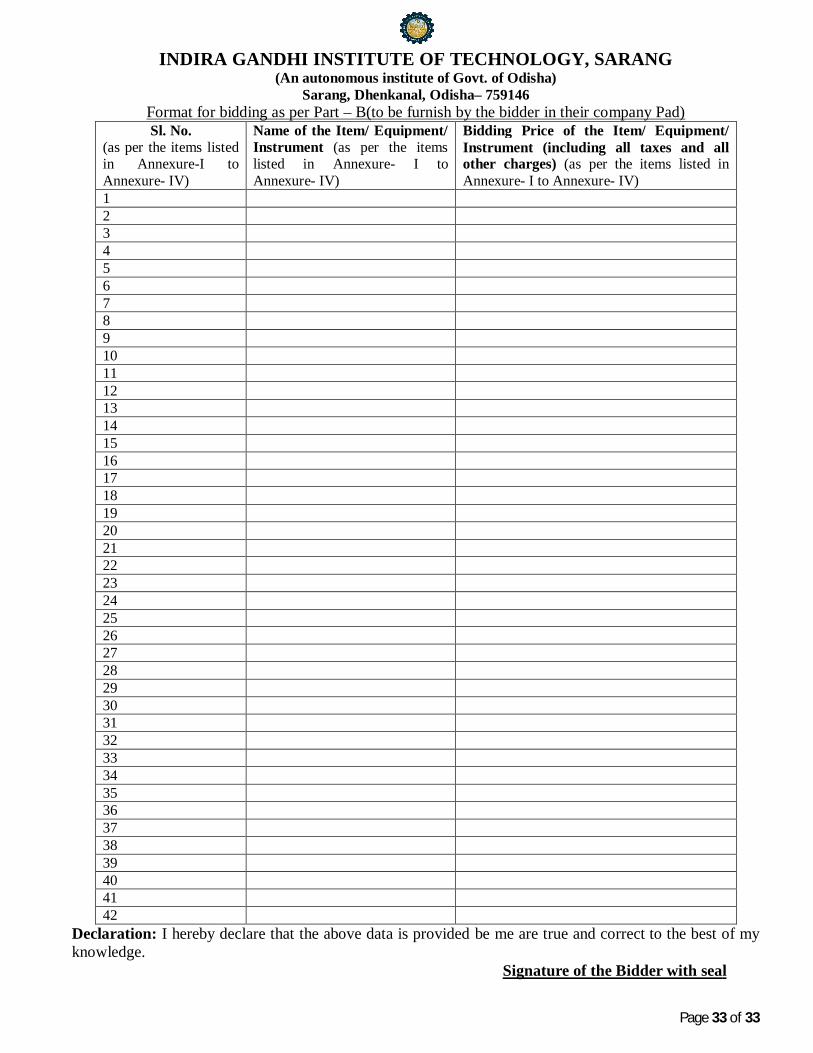
Format for bidding as per Part – B(to be furnish by the bidder in their company Pad) Sl. No.
(as per the items listed in Annexure-I to Annexure- IV)
Name of the Item/ Equipment/ Instrument (as per the items listed in Annexure- I to Annexure- IV)
Bidding Price of the Item/ Equipment/ Instrument (including all taxes and all other charges) (as per the items listed in Annexure- I to Annexure- IV)
Declaration: I hereby declare that the above data is provided be me are true and correct to the best of my knowledge. Signature of the Bidder with seal