IEEE TRANSACTIONS ON CONTROL SYSTEMS TECHNOLOGY, VOL. 11, NO. 6, NOVEMBER 2003 875
Indirect Stator Flux-Oriented Output FeedbackControl of a Doubly Fed Induction Machine
Sergei Peresada, Andrea Tilli, and Alberto Tonielli, Associate Member, IEEE
Abstract—A new indirect stator flux field-oriented output feed-back control for Doubly Fed Induction Machine is presented. Itassures global exponential torque tracking and stabilization of thestator-side power factor at unity level, provided that electric ma-chine physical constraints are satisfied. Based on the inner torquecontrol system, a speed tracking controller, with load torque com-pensation is designed using passivity approach. In contrast to ex-isting solutions, the stator voltage vector oriented reference frameis adopted in order to improve robustness properties with respect toinduction machine parameters variation. To achieve smooth con-nection of electric machine to the line grid a synchronization algo-rithm is developed for excitation stage of the Doubly Fed InductionMachine operation. The solution proposed requires measurementsof line voltages, rotor currents, rotor position and speed. Intensiveexperimental studies demonstrate high dynamic performance ca-pabilities of the control algorithm proposed.
Index Terms—AC generators, AC motor drives, electric ma-chines, Lyapunov-based control, power control, torque control,velocity control.
I. INTRODUCTION
M ODERN induction motor drives are the most widelyused industrial electromechanical systems. During the
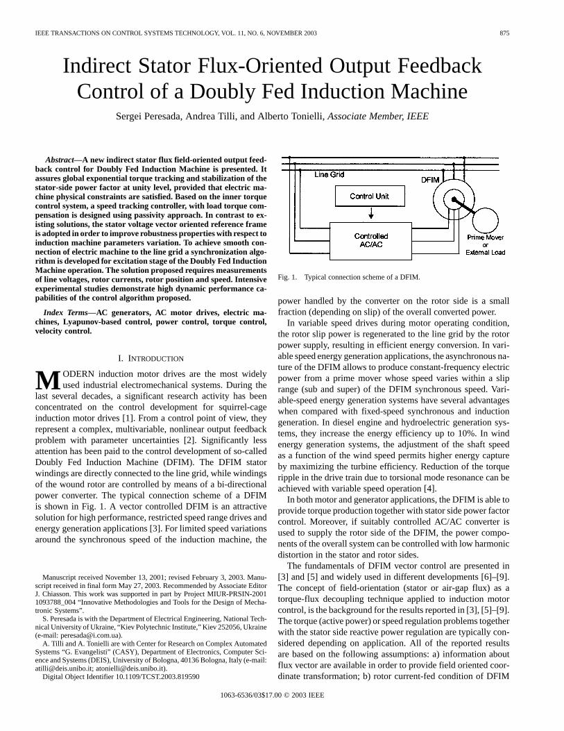
last several decades, a significant research activity has beenconcentrated on the control development for squirrel-cageinduction motor drives [1]. From a control point of view, theyrepresent a complex, multivariable, nonlinear output feedbackproblem with parameter uncertainties [2]. Significantly lessattention has been paid to the control development of so-calledDoubly Fed Induction Machine (DFIM). The DFIM statorwindings are directly connected to the line grid, while windingsof the wound rotor are controlled by means of a bi-directionalpower converter. The typical connection scheme of a DFIMis shown in Fig. 1. A vector controlled DFIM is an attractivesolution for high performance, restricted speed range drives andenergy generation applications [3]. For limited speed variationsaround the synchronous speed of the induction machine, the
Manuscript received November 13, 2001; revised February 3, 2003. Manu-script received in final form May 27, 2003. Recommended by Associate EditorJ. Chiasson. This work was supported in part by Project MIUR-PRSIN-20011093788_004 “Innovative Methodologies and Tools for the Design of Mecha-tronic Systems”.
S. Peresada is with the Department of Electrical Engineering, National Tech-nical University of Ukraine, “Kiev Polytechnic Institute,” Kiev 252056, Ukraine(e-mail: [email protected]).
A. Tilli and A. Tonielli are with Center for Research on Complex AutomatedSystems “G. Evangelisti” (CASY), Department of Electronics, Computer Sci-ence and Systems (DEIS), University of Bologna, 40136 Bologna, Italy (e-mail:[email protected]; [email protected]).
Digital Object Identifier 10.1109/TCST.2003.819590
Fig. 1. Typical connection scheme of a DFIM.
power handled by the converter on the rotor side is a smallfraction (depending on slip) of the overall converted power.
In variable speed drives during motor operating condition,the rotor slip power is regenerated to the line grid by the rotorpower supply, resulting in efficient energy conversion. In vari-able speed energy generation applications, the asynchronous na-ture of the DFIM allows to produce constant-frequency electricpower from a prime mover whose speed varies within a sliprange (sub and super) of the DFIM synchronous speed. Vari-able-speed energy generation systems have several advantageswhen compared with fixed-speed synchronous and inductiongeneration. In diesel engine and hydroelectric generation sys-tems, they increase the energy efficiency up to 10%. In windenergy generation systems, the adjustment of the shaft speedas a function of the wind speed permits higher energy captureby maximizing the turbine efficiency. Reduction of the torqueripple in the drive train due to torsional mode resonance can beachieved with variable speed operation [4].
In both motor and generator applications, the DFIM is able toprovide torque production together with stator side power factorcontrol. Moreover, if suitably controlled AC/AC converter isused to supply the rotor side of the DFIM, the power compo-nents of the overall system can be controlled with low harmonicdistortion in the stator and rotor sides.
The fundamentals of DFIM vector control are presented in[3] and [5] and widely used in different developments [6]–[9].The concept of field-orientation (stator or air-gap flux) as atorque-flux decoupling technique applied to induction motorcontrol, is the background for the results reported in [3], [5]–[9].The torque (active power) or speed regulation problems togetherwith the stator side reactive power regulation are typically con-sidered depending on application. All of the reported resultsare based on the following assumptions: a) information aboutflux vector are available in order to provide field oriented coor-dinate transformation; b) rotor current-fed condition of DFIM
876 IEEE TRANSACTIONS ON CONTROL SYSTEMS TECHNOLOGY, VOL. 11, NO. 6, NOVEMBER 2003
operation; c) stator resistance is negligible. Under such condi-tions, reduced order torque and stator-side reactive power con-trol problem is transferred to the rotor current control problemif the rotor currents are defined in the field-oriented referenceframe. Assumption of negligible stator resistance is needed inorder to establish the condition of DFIM operation with constantstator flux modulus. Direct field-orientation is considered onthe base of the flux vector information, which can be computedfrom the stator and rotor current measurements or obtained fromthe integration of the stator voltage differential equations.
The structure of standard DFIM controllers considered in[3], [5]–[9] includes two-axis rotor current control loops withhigh-gain PI current controllers, implemented in flux orientedreference frame. Two rotor current references serve as scaledreferences for torque and reactive power. Speed and reactivepower outer control loops can be added [3], [5]. In [10], a statefeedback linearization technique has been applied to solveDFIM control problem. The rotor current-fed assumption isused with an additional first order filter in the control loop.The comparison of the power control dynamics in the fieldoriented and rotor oriented coordinate frames is given in [11].Position sensorless solutions have been considered in [7], [9],[12]. A number of publications report results on the successfulexperimental testing of vector controlled DFIM. The generalidea behind all direct field oriented control strategies is thatstator (or air-gap) flux is available from indirect measurements.Since in DFIM both stator and rotor currents are available frommeasurements, the flux vectors (stator, air-gap or rotor) canbe computed using flux current static equations. Nevertheless,the flux vector computation involves the transformation of onecurrent vector into stationary or rotor-oriented reference frame,using high precision position information. Moreover, the staticflux-current relation is dependent on the electric machineinductances. The saturation effect should be considered in theflux computation from the measured stator and rotor currents,since DFIM with power factor control operates with the varyingflux amplitude, dependent on the produced torque. Open loopintegration of the stator voltage equations in order to get statorfluxes has obvious and well-known practical limitations due tovariation of stator resistance and open loop integration drift.
In [13], the authors introduced an alternative approach forvector control of DFIM. For the first time the full order con-trol problem, with no assumption of negligible stator resistance,has been considered. A torque—stator-side reactive power con-troller has been developed in a line-voltage oriented referenceframe. Since the line voltage can be easily measured with negli-gible errors, this reference frame is independent of the parame-ters of the DFIM in contrast with the field-oriented frame. More-over, information about line voltage is typically needed to per-form soft connection of the DFIM to the line grid during the pre-liminary excitation-synchronization stage. The controller pro-posed in [13] guarantees global asymptotic torque tracking andunity stator-side power factor stabilization during steady state.In [14], the approach of [13] is extended to speed tracking atstator-side power factor stabilization control problem under as-sumption of rotor current fed conditions. Both controllers [13]and [14] are based on the measurement of rotor currents androtor speed/position only, and consequently can be classified
as output feedback controllers. The output feedback problemof DFIM appears even more complex as compared with thesquirrel cage induction machine control. In contrast to vectorcontrol of a standard induction machine, where output variablesto be controlled are torque and rotor flux modulus, torque andstator flux angle need to be controlled in order to achieve thestator side reactive power control of DFIM.
The aim of this paper is to present a new output feedback con-trol of the DFIM. The solution proposed provides Indirect StatorFlux Orientation (ISFO), which corresponds, in principle, to In-direct Rotor Flux Orientation (IRFO) for squirrel-cage induc-tion motor, but it must be emphasized that the control designpath adopted is substantially different with respect to the caseof classical induction motor controllers based on IRFO.
Specifically, the torque tracking, stator-side unity powerfactor control problem is considered first, with the requirementto achieve global exponentially stable rotor current and statorflux error dynamics, independently of speed behavior. It isdemonstrated that conditions of stator flux field orientation andline voltage orientation are equivalent if the stator side powerfactor is controlled at unity level. Under such a condition, thestator flux modulus is not a free output variable, but rather it isa function of the produced electromagnetic torque.
The torque tracking is then extended to the speed trackingproblem in the presence of an unknown constant load torque,using a passivity-based approach. It is shown that exponentialspeed tracking and stator-side power factor stabilization islocally achievable, provided that the speed references andtheir time derivatives, as well as load torque, are properlybounded. The proposed controller decomposes the originalDFIM dynamics in two interconnected subsystems: mechanicaland electrical, providing asymptotic linearization of the speed(mechanical) subsystem. As far as the authors know, it is a firstsolution of the full order speed tracking problem for this classof electric machine. An intensive experimental study showsthat high performance torque tracking is achievable whilekeeping the stator side power factor at unity during the energygeneration regime. For drive application, high precision speedtracking is experimentally demonstrated.
The paper is organized as follows. In Section II the DFIMmodel and control problem statement are presented. Torquetracking controller and speed tracking controller, togetherwith the stator-side unity power factor stabilizing controller,are designed in Sections III and IV correspondingly. Systeminitialization procedure is given in Section V. Results of theexperimental tests are presented in Section VI.
II. DFIM M ODEL AND CONTROL PROBLEM STATEMENT
A. DFIM Model
The equivalent two-phase model of the symmetrical DFIM,under the assumptions of linear magnetic circuits and balancedoperating conditions, is represented in an arbitrary rotating (d-q)reference frame as [3]
(1)
PERESADAet al.: INDIRECT STATOR FLUX-ORIENTED OUTPUT FEEDBACK CONTROL 877
(2)
(3)
The parameters of the electric machine are defined as follows:
where , are stator/rotor resistances and induc-tances, is the mutual inductance, is 4 4 inductancematrix J is the total rotor inertia, is theviscous friction coefficient. One pole pair is assumed withoutloss of generality.
Subscripts 1, 2 are used to indicate stator and rotor variablesrespectively; subscripts d,q indicate vector components in therotating (d-q) reference frame. Variables are the rotorangle position and speed, is an external load torque,
are stator and rotor voltage and current vectors. Thevariable is the angular position of the (d-q) reference framewith respect to a fixed stator reference frame (a-b). Variables inthe rotating reference frame are related to their correspondingin the stator and rotor reference frames as follows:
(4)
where represents two phase
equivalent voltage, current, flux vectors; superscript (dr, qr) de-notes vectors in a reference frame fixed to the rotor.
Flux linkages and currents are related by
(5)
where .According to (1) and (2), the electric machine has two control
inputs given by stator and rotor voltage vectors . Whenthe DFIM connected to the line is considered, the stator voltagevector is fixed by
where are the (constant) amplitude and angular fre-quency of the line voltage, generated by an ideal voltage sourceof infinite power; .
The line voltage source can be viewed as an additional (notcontrolled) excitation input of the DFIM, providing redundancyfor the joined action of the two controls . As compared
with the squirrel cage induction machine (where ) thisallows one to achieve the main control objectives of electro-mechanical energy conversion together with the optimization ofenergy efficiency, using the additional degree of freedom in thecontrol.
B. Output Feedback Control Objectives
Referring to the general machine model (1), (2), (5), considerthe DFIM model represented in terms of stator fluxes and rotorcurrents as
(6)
where.
The generated torque is equal to
(7)
where .Two main classes of DFIM applications are considered.
When the DFIM is used as generator, the torquein the firstequation of (6) is a mechanical input torque, generated by aprime mover, and used to stabilize the mechanical system, asfollows:
(8)
where is the speed controller gain of the prime moverand is the prime mover’s speed reference. The elec-tromagnetic torque T of the DFIM is the load torque for themechanical system (8) of the prime energy converter. The maincontrol objective of the DFIM operating as a generator is to pro-duce the desired generated torque independent of .
In electrical drive applications, the DFIM torque T is the elec-tromagnetically produced torque that controls the speed of themechanical system and is an external load torque. A speedcontrol objective is typically defined for such applications.
For the abovementioned tasks, the following output feedbackcontrol objectives are defined. Consider the DFIM model, givenby (6) and (7) and assume the following:
A1) the stator voltage amplitude and frequency are constant(the stator windings are directly connected to the linegrid);
A2) rotor position and speed, stator voltages, and rotor cur-rents are available from the measurements;
A3) DFIM parameters are known and constant.Under these conditions, it is required to design an output feed-back control algorithm (rotor voltage vector ) whichguarantees the following.
878 IEEE TRANSACTIONS ON CONTROL SYSTEMS TECHNOLOGY, VOL. 11, NO. 6, NOVEMBER 2003
1) For Energy Generation Systems:O.1–1 Global asymp-totic torque tracking under condition of stator flux field-orien-tation, i.e., with
(9.a)
(9.b)
where is the torque error and is a bounded torque referencetrajectory with bounded first and second derivatives.
O.1–2 A smooth transient-free connection of the stator wind-ings to the line grid during the start-up procedure.
2) For the Electric Drives Application:O.2–1 Asymptoticspeed tracking together with the condition of asymptotic statorflux field-orientation under the condition of constant boundedload torque, i.e.,
(10)
where is the speed tracking error and is a bounded speedreference trajectory with bounded first, second and third timederivatives.
It is important to note that speed control objective is requiredalso for some energy generation systems such as wind powerplants when turbine efficiency control is applied [8].
In the next section, it is shown that the condition ofstator flux orientation guarantees that
during steady-state conditionwith constant torque, i.e., stator reactive power asymptoticallytends to zero when the torque reference is constant.
The torque-tracking problem is solved first to provide globalexponential asymptotic properties for the DFIM electric sub-system. Then the speed tracking and load compensation con-troller is designed for the outer speed control loop.
III. D ESIGN OF THETORQUE-TRACKING CONTROLLER
In [13], the authors first proposed the use of a stator voltagevector oriented reference frame, instead of a stator flux orientedframe, for the control of a DFIM. The line voltage-vector anglecan be easily measured with negligible errors thus avoiding anystator current measurements.
The stator voltage oriented coordinate transformation is de-fined by setting in (3) and (4)
(11)
Under such transformation stator flux dynamics (6) becomes
(12)
Defining the flux errors as
(13)
where is the q-axis flux reference trajectory and is the
reference for stator flux modulus , the torque-fluxerror dynamics can be written as
(14)
Assuming the rotor current-fed condition, the followingtorque-flux control algorithm is constructed.
• Torque control algorithm
(15)
• Flux level (q-axis) control algorithm
(16)
with the q-axis flux reference manifold given by
(17)
The torque-flux error dynamics, generated by the control algo-rithm (15) to (17) is
(18)
The solution
(19)
is a globally exponentially stable equilibrium point of thesystem (18) which has linear time invariant dynamics witheigenvalues . From (19) it fol-lows that requirements (9) of stator flux field-orientation
and torque control objectives areachieved.
The q-axis flux reference computed from (17) and (15) isequal to
(20)
Remark 1: The q-axis flux reference is negative according tothe particular choice of the reference frame.
Remark 2: Equation (20) establishes the physical limitationof the DFIM torque production with unity power factor at thestator side during motor operation.
From (19) and (20) it can be concluded that in the steadystate (with and constant),(see (16)), which implies that (see(5)), and operation with zero stator-side reactive power
isachieved.
Remark 3: According to previous consideration, the flux ori-entation (9.b) imposed by the proposed algorithm is sufficient toguarantee zero reactive power at stator side in steady-state. It is
PERESADAet al.: INDIRECT STATOR FLUX-ORIENTED OUTPUT FEEDBACK CONTROL 879
worth noting that (9.b) is also necessary for the above conditionabout stator reactive power. In fact, considering the stator equa-tions in terms of stator fluxes and currents in the line voltagereference frame
it results that is necessary to guarantee insteady-state .
Remark 4: Since conditions of the stator flux field-orienta-tion are achieved without flux measurement (computation or es-timation) the proposed approach can be viewed as an indirectstator field-orientation, based on passivity of the electric ma-chine stator circuit.
In an actual DFIM, the rotor currents are not available as con-trol inputs and the torque-flux controller outputs in(15) and (16) can only represent desired trajectoriesfor the real currents . The rotor voltage vector
is the only physically available control input ofDFIM. The current loop control algorithm should be designedto guarantee that current tracking errors
(21)
asymptotically decay to zero.The rotor current dynamics is given by fourth and fifth equa-
tions in (6), with . By defining the currentcontrollers control algorithm as
(22)
the stator-flux rotor-current error dynamics becomes
(23)
where is the current controller proportional gain andthe derivative of the current references are computed from thetorque-flux controller (15), (16) with real currents replaced bytheir references. To show that the current tracking control ob-jective is achieved, consider the following Lyapunov function:
(24)
which is positive definite if .The time derivative of V along the trajectories of (23) is equal
to
(25)
From (25) it follows that for any there existsuch that , therefore, the equilibrium point
(26)
is globally exponentially stable, i.e.,
(27)
Global stator flux field orientation and current tracking isachieved according to (27) with bounded internal signals pro-vided that DFIM physical constraint
in (20) is satisfied. The torque error equation from (14) and(21) is given by
(28)
and torque-tracking objective directly follows from condition(27).
The resulting torque-flux-current error dynamics is given by(23), (28). The torque-flux controllers equations are given by(15), (16) with replaced with , (20) and the rotorcurrent controllers (22).
Remark 5: According to the results proposed by the authorsin [13], an integral action can be added in the current controller(22). From the application view point, high gains in the propor-tional and integral feedback actions allow to remove the feed-forward actions in (22) preserving “practical stability”, owingto time scale separation between rotor current and stator fluxdynamics.
Remark 6: The indirect stator field orientation provided bythe proposed controller is based on the strict passivity of theDFIM stator circuit. The structure of flux and current error dy-namics is similar to rotor flux and stator current error dynamicsobtained when indirect rotor flux field-oriented control is ap-plied to squirrel cage Induction Motor (IM) [16]. Nevertheless,the physics of indirect field-orientation is different for the twocases. Amplitude of the rotor flux vector can be arbitrary con-trolled (according to saturation bounds) in standard IM drives,while angle position of the rotor flux vector is not a degree offreedom for the field-oriented controller. In the case of DFIM,the space position of the synchronous reference frame is givenby the stator line voltage vector and angle position of the statorflux vector (orthogonal to line voltage vector) is controlled byspecifying its amplitude as a function of the produced torque.
IV. SPEEDTRACKING CONTROLLER DESIGN
In this section, the speed-tracking and load compensation al-gorithm is designed on the basis of the inner torque tracking sub-system developed in Section III. The property of global asymp-totic exponential stability of the electrical subsystem is used tospecify the desired dynamics of the electric drive mechanicalsubsystem. The approach adopted here is similar to the one con-sidered in [15] for squirrel cage IM control and based on pas-sivity theory.
Since the norm of the electrical variables in (27) ex-ponentially decays to zero independently of the motor speed, thetorque error converges to zero if flux and current references in(28) do not grow faster than the exponential function.
880 IEEE TRANSACTIONS ON CONTROL SYSTEMS TECHNOLOGY, VOL. 11, NO. 6, NOVEMBER 2003
The speed error dynamics can be computed using the firstequation in (6), as follows:
(29)
where is defined in (28), is the estimation of the constantload torque component and the load torque estimationerror is defined as .
Define the desired torque trajectory, generated by the speedcontroller, as
(30)
(31)
where are proportional and integral gains of thespeed controller and is the speed filter time constant. Substi-tuting (30) and (31) in (29) the speed error dynamics becomes
(32)
The nominal dynamics of the speed subsystem islinear and can be designed to achieve the desired transient per-formance by selection of gains of the PI speed controllerand time constant of the speed filter. Note that a second-orderfilter has been inserted in order to generate the reference tra-jectory for and , required for the computation of the fluxderivative reference trajectories in (16), (20) and current refer-ence derivatives in (22).
The speed controller design, according to (29) to (32), intro-duces additional speed filter dynamics, which can be designedarbitrary fast with small enough in order to be negligible ascompared to basic nominal speed error dynamics given by thereduced order system (with )
(33)
The total error dynamics of the mechanical and electrical sub-systems is given by (32) and (18) for rotor current-fed DFIMand by (23), (28), (32) for the full order case.
Before proceeding to the investigation of stability propertiesof the full order error dynamics it is worth considering the fol-lowing remark.
Remark 7: The torque tracking control algorithm is globallyasymptotically exponentially stable provided that torque refer-
ence in (20) is bounded according to physical DFIM con-straint
(34)
Condition (34) takes into account the effect of the voltage dropon stator circuit resistance in DFIM stator-side power balanceequation. Such condition exists for all energy converters con-nected to ac line source. For standard IM, stator resistance isquite small and is sufficiently higher than the motor max-imum torque . As a result, during physical operatingconditions of DFIM inside of motor and converter current andvoltage limits inequality (34) is always satisfied and the torqueproduction capabilities of the electrical machine are completelyutilized.
During closed-loop speed operation the torque reference isgenerated by the speed controller according to (30) and, in gen-eral, condition (34) can be violated. Consequently, the speed ref-erence trajectory, the controller initialization as well as the se-quence of motor operation must be properly specified in ordernot to violate the physical constraint (34) on the motor opera-tion. To specify the speed reference trajectory and load condi-tions, rewrite (30) as
(35)
The “external” torque reference should be only one part ofthe maximum torque . The system initialization procedureshould guarantee that the “dynamic” part of the torque reference
satisfies condition . Additionally, lim-iting the output of the speed controller protects the motor-con-verter system from over-current conditions. The current limitingprocedure is given by
(36)
If during undesirable transients the speed controller output issaturated according to (36), then the speed tracking performanceis lost while the torque-flux subsystem remains asymptoticallystable.
In the following stability analysis, it is assumed that condi-tions (34) is satisfied. The flux reference (20) can be presentedas
(37)
Since by assumption it follows that andthere exist two constants such that
(38)
PERESADAet al.: INDIRECT STATOR FLUX-ORIENTED OUTPUT FEEDBACK CONTROL 881
From (37) and (38) it follows that
(39)
and the flux reference derivative
(40)
is also bounded if is bounded.Using (30), (31), (37), and (40) the torque tracking error (28)
can be written as
(41)
By using (41) and defining the state space vectors of mechanicaland electrical subsystems as
(42)
the total system error dynamics (32), (41), and (23) can be pre-sented as a feedback interconnection of the mechanical and elec-trical subsystems, whose general form is
(43)
Using result reported in [16] it can be proven that the equilib-rium point of system (43) is asymptotically ex-ponentially stable since the following conditions hold:
1) the subsystem given by the state space vectoris glob-ally asymptotically exponentially stable for every trajec-tory of such that condition (34) is satisfied
2)
3)
Note that with respect [16], the matrix depends explicitlyon , but, owing to (39), condition 3) reported above holds andthe result of [16] can be applied.
The property of exponential stability of the electricalsubsystem has been given in Section III. Conditions 2) and3) follows from the structure of the torque regulation error(41). Since bounds are based on conditions (34),(37)(38)(39)–(40), the stability is local in general sense.Nevertheless, full demagnetization of the DFIM due to statorresistance voltage drop is physically not possible under limitedcurrents and supply rotor voltages (specifically for DFIMoperation with restricted speed range and strictly limited rotorside voltage). Therefore practical stability should be guaranteedby applying appropriate selection of speed references andinitialization of system as discussed above.
Speed tracking directly follows from asymptotic stability ofthe system (43). Stator flux field-orientation is achieved ac-cording to (27) independently of speed control. Additionally,when the system is in steady state with , operationwith zero reactive power at the stator side is guaranteed.
The overall system error dynamics, whose general form isgiven by (43), has important properties.
1) The mechanical and electrical dynamics are asymptot-ically decoupled, namely, the manifold is anasymptotically stable invariant, with a dynamics given by
(indicated as nominal error dynamics of me-chanical-part). Moreover, if , the mechanicaldynamics can be viewed as the sum of the nominal dy-namics and a vanishing perturbation, generated by elec-trical subsystem.
2) Asymptotic linearization of the mechanical subsystem isachieved since its error dynamics asymptotically tends tothe nominal linear one. Standard optimization techniquesfor linear systems can be applied to design the systemmatrix of the nominal dynamics of (32).
The complete equations of the proposed output feedback con-troller are as follows.
Stator flux vector controller
(44)
Torque controller
(45)
Rotor current controllers
(46)
Speed controller
(47)
882 IEEE TRANSACTIONS ON CONTROL SYSTEMS TECHNOLOGY, VOL. 11, NO. 6, NOVEMBER 2003
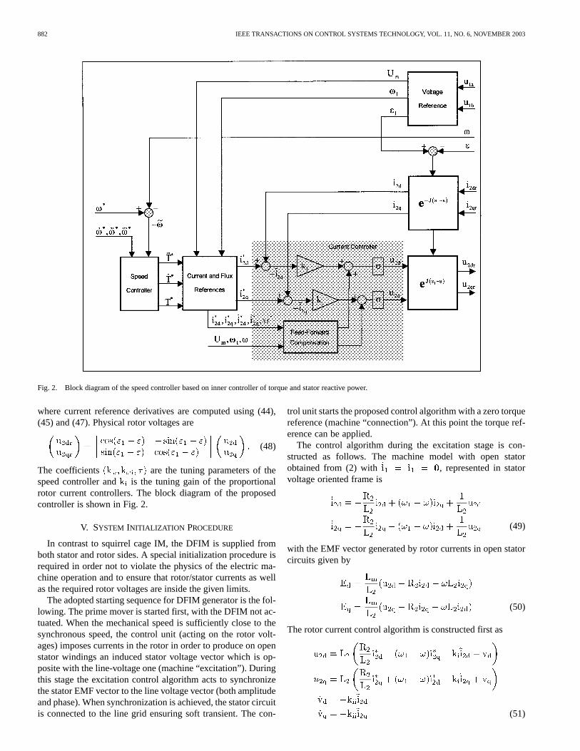
Fig. 2. Block diagram of the speed controller based on inner controller of torque and stator reactive power.
where current reference derivatives are computed using (44),(45) and (47). Physical rotor voltages are
(48)
The coefficients are the tuning parameters of thespeed controller and is the tuning gain of the proportionalrotor current controllers. The block diagram of the proposedcontroller is shown in Fig. 2.
V. SYSTEM INITIALIZATION PROCEDURE
In contrast to squirrel cage IM, the DFIM is supplied fromboth stator and rotor sides. A special initialization procedure isrequired in order not to violate the physics of the electric ma-chine operation and to ensure that rotor/stator currents as wellas the required rotor voltages are inside the given limits.
The adopted starting sequence for DFIM generator is the fol-lowing. The prime mover is started first, with the DFIM not ac-tuated. When the mechanical speed is sufficiently close to thesynchronous speed, the control unit (acting on the rotor volt-ages) imposes currents in the rotor in order to produce on openstator windings an induced stator voltage vector which is op-posite with the line-voltage one (machine “excitation”). Duringthis stage the excitation control algorithm acts to synchronizethe stator EMF vector to the line voltage vector (both amplitudeand phase). When synchronization is achieved, the stator circuitis connected to the line grid ensuring soft transient. The con-
trol unit starts the proposed control algorithm with a zero torquereference (machine “connection”). At this point the torque ref-erence can be applied.
The control algorithm during the excitation stage is con-structed as follows. The machine model with open statorobtained from (2) with , represented in statorvoltage oriented frame is
(49)
with the EMF vector generated by rotor currents in open statorcircuits given by
(50)
The rotor current control algorithm is constructed first as
(51)
PERESADAet al.: INDIRECT STATOR FLUX-ORIENTED OUTPUT FEEDBACK CONTROL 883
Fig. 3. Experimental setup.
where are the proportional and integral gains of thePI current controllers.
For constant current references the EMF equations and theerror dynamics of rotor currents during excitation becomes
(52)
(53)
The rotor current subsystem is globally asymptotically stablefor all . To define the EMF reference it can be notedthat the voltage line vector is aligned with the d-axis, thereforeEMF references are
(54)
Consequently, the references for rotor current are
(55)
From (52) and (53) it can be concluded that synchronization isachieved with transient performance defined by the dynamicsof the rotor current subsystem (53). Note that: a) the currentreferences given by (55) are the same as in (15), (16), (20), with
; and b) the structure of the current controller (51)is a part of the general current controller (22), with additionalintegral actions.
The start-up of the DFIM during motor operating conditionsare typically achieved with additional rotor resistances [3] orusing semiconductor soft-starter. When induction machinespeed is inside the controllable slip range (according to rotorvoltage limits), the speed control algorithm can be actuated,setting the initial condition for speed reference equal to actualrotor speed.
VI. EXPERIMENTAL RESULTS
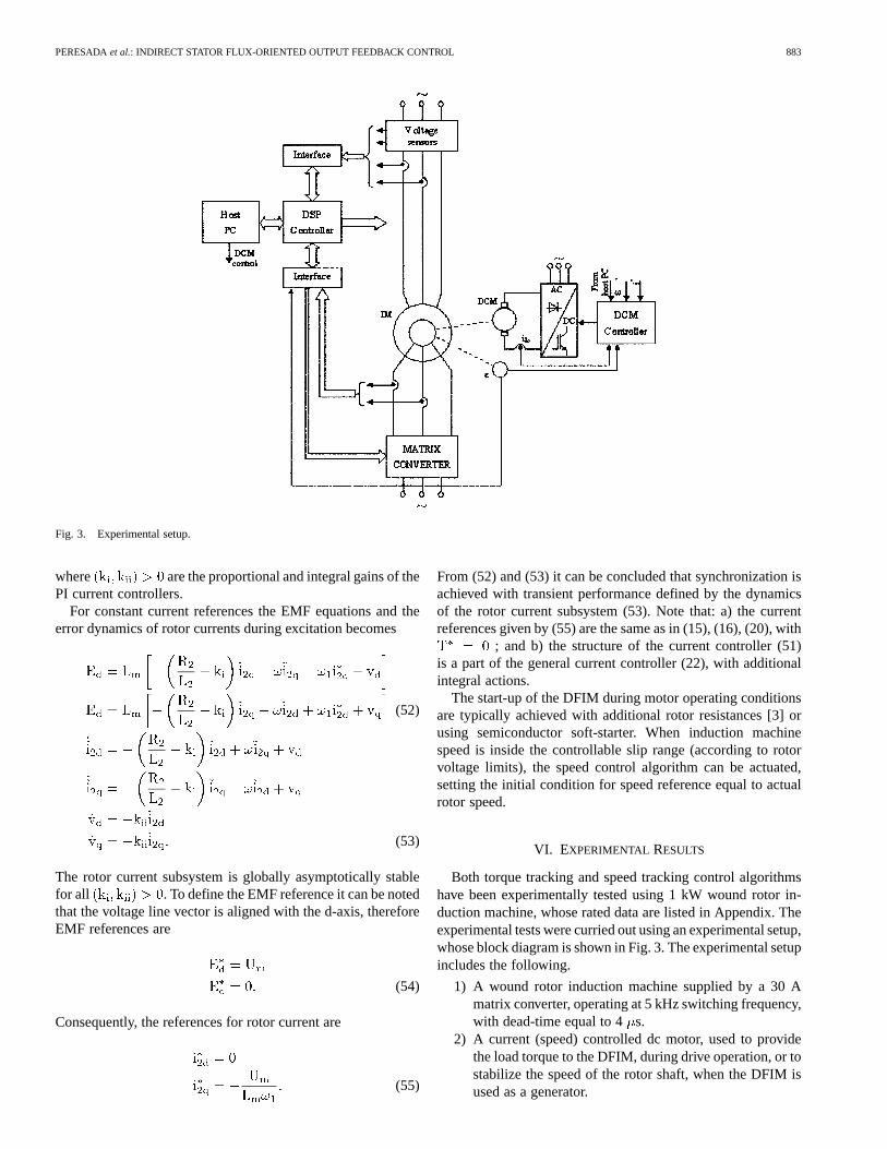
Both torque tracking and speed tracking control algorithmshave been experimentally tested using 1 kW wound rotor in-duction machine, whose rated data are listed in Appendix. Theexperimental tests were curried out using an experimental setup,whose block diagram is shown in Fig. 3. The experimental setupincludes the following.
1) A wound rotor induction machine supplied by a 30 Amatrix converter, operating at 5 kHz switching frequency,with dead-time equal to 4s.
2) A current (speed) controlled dc motor, used to providethe load torque to the DFIM, during drive operation, or tostabilize the speed of the rotor shaft, when the DFIM isused as a generator.
884 IEEE TRANSACTIONS ON CONTROL SYSTEMS TECHNOLOGY, VOL. 11, NO. 6, NOVEMBER 2003
(a)
(b)
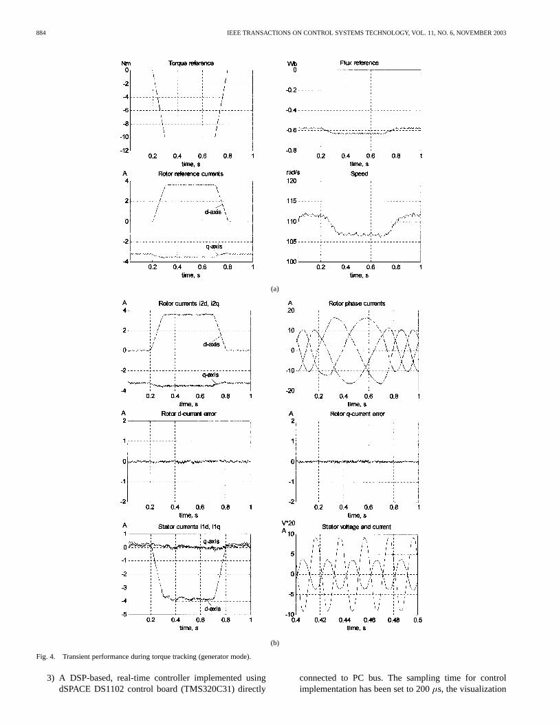
Fig. 4. Transient performance during torque tracking (generator mode).
3) A DSP-based, real-time controller implemented usingdSPACE DS1102 control board (TMS320C31) directly
connected to PC bus. The sampling time for controlimplementation has been set to 200s, the visualization
PERESADAet al.: INDIRECT STATOR FLUX-ORIENTED OUTPUT FEEDBACK CONTROL 885
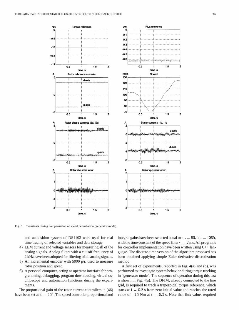
Fig. 5. Transients during compensation of speed perturbation (generator mode).
and acquisition system of DS1102 were used for realtime tracing of selected variables and data storage.
4) LEM current and voltage sensors for measuring all of theanalog signals. Analog filters with a cut-off frequency of2 kHz have been adopted for filtering of all analog signals.
5) An incremental encoder with 5000 p/r, used to measurerotor position and speed.
6) A personal computer, acting as operator interface for pro-gramming, debugging, program downloading, virtual os-cilloscope and automation functions during the experi-ments.
The proportional gain of the rotor current controllers in (46)have been set at . The speed controller proportional and
integral gains have been selected equal to ,with the time constant of the speed filter ms. All programsfor controller implementation have been written using C++ lan-guage. The discrete-time version of the algorithm proposed hasbeen obtained applying simple Euler derivative discretizationmethod.
A first set of experiments, reported in Fig. 4(a) and (b), wasperformed to investigate system behavior during torque trackingin “generator mode”. The sequence of operation during this testis shown in Fig. 4(a). The DFIM, already connected to the linegrid, is required to track a trapezoidal torque reference, whichstarts at s from zero initial value and reaches the ratedvalue of Nm at s. Note that flux value, required
886 IEEE TRANSACTIONS ON CONTROL SYSTEMS TECHNOLOGY, VOL. 11, NO. 6, NOVEMBER 2003
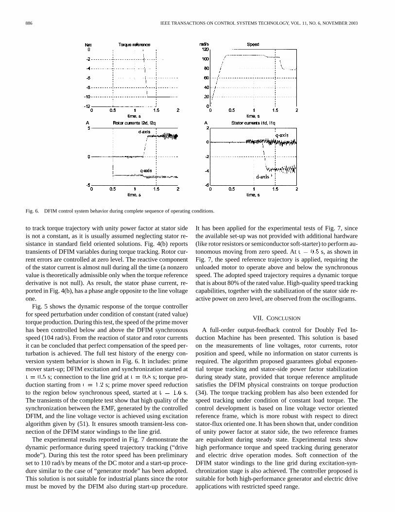
Fig. 6. DFIM control system behavior during complete sequence of operating conditions.
to track torque trajectory with unity power factor at stator sideis not a constant, as it is usually assumed neglecting stator re-sistance in standard field oriented solutions. Fig. 4(b) reportstransients of DFIM variables during torque tracking. Rotor cur-rent errors are controlled at zero level. The reactive componentof the stator current is almost null during all the time (a nonzerovalue is theoretically admissible only when the torque referencederivative is not null). As result, the stator phase current, re-ported in Fig. 4(b), has a phase angle opposite to the line voltageone.
Fig. 5 shows the dynamic response of the torque controllerfor speed perturbation under condition of constant (rated value)torque production. During this test, the speed of the prime moverhas been controlled below and above the DFIM synchronousspeed (104 rad/s). From the reaction of stator and rotor currentsit can be concluded that perfect compensation of the speed per-turbation is achieved. The full test history of the energy con-version system behavior is shown in Fig. 6. It includes: primemover start-up; DFIM excitation and synchronization started at
s; connection to the line grid at s; torque pro-duction starting from s; prime mover speed reductionto the region below synchronous speed, started at s.The transients of the complete test show that high quality of thesynchronization between the EMF, generated by the controlledDFIM, and the line voltage vector is achieved using excitationalgorithm given by (51). It ensures smooth transient-less con-nection of the DFIM stator windings to the line grid.
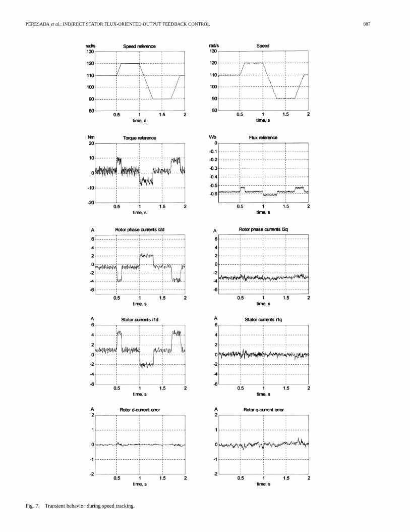
The experimental results reported in Fig. 7 demonstrate thedynamic performance during speed trajectory tracking (“drivemode”). During this test the rotor speed has been preliminaryset to 110 rad/s by means of the DC motor and a start-up proce-dure similar to the case of “generator mode” has been adopted.This solution is not suitable for industrial plants since the rotormust be moved by the DFIM also during start-up procedure.
It has been applied for the experimental tests of Fig. 7, sincethe available set-up was not provided with additional hardware(like rotor resistors or semiconductor soft-starter) to perform au-tonomous moving from zero speed. At s, as shown inFig. 7, the speed reference trajectory is applied, requiring theunloaded motor to operate above and below the synchronousspeed. The adopted speed trajectory requires a dynamic torquethat is about 80% of the rated value. High-quality speed trackingcapabilities, together with the stabilization of the stator side re-active power on zero level, are observed from the oscillograms.
VII. CONCLUSION
A full-order output-feedback control for Doubly Fed In-duction Machine has been presented. This solution is basedon the measurements of line voltages, rotor currents, rotorposition and speed, while no information on stator currents isrequired. The algorithm proposed guarantees global exponen-tial torque tracking and stator-side power factor stabilizationduring steady state, provided that torque reference amplitudesatisfies the DFIM physical constraints on torque production(34). The torque tracking problem has also been extended forspeed tracking under condition of constant load torque. Thecontrol development is based on line voltage vector orientedreference frame, which is more robust with respect to directstator-flux oriented one. It has been shown that, under conditionof unity power factor at stator side, the two reference framesare equivalent during steady state. Experimental tests showhigh performance torque and speed tracking during generatorand electric drive operation modes. Soft connection of theDFIM stator windings to the line grid during excitation-syn-chronization stage is also achieved. The controller proposed issuitable for both high-performance generator and electric driveapplications with restricted speed range.
PERESADAet al.: INDIRECT STATOR FLUX-ORIENTED OUTPUT FEEDBACK CONTROL 887
Fig. 7. Transient behavior during speed tracking.
888 IEEE TRANSACTIONS ON CONTROL SYSTEMS TECHNOLOGY, VOL. 11, NO. 6, NOVEMBER 2003
APPENDIX
RATED DATA OF THE ADOPTEDDFIM
REFERENCES
[1] R. Ortega, G. Asher, and E. Mendes, “Editorial to special issue on in-duction motor control,”Int. J. Adaptive Contr. Signal Processing, vol.14, pp. 79–81, 2000.
[2] R. Marino, S. Peresada, and P. Tomei, “Global adaptive output feedbackcontrol of induction motors with uncertain rotor resistance,”IEEE Trans.Automat. Contr., vol. 44, pp. 967–983, May 1999.
[3] W. Leonhard,Control of Electric Drives, Berlin: Springer-Verlag, 1995.[4] H. L. Nakra and B. Duke, “Slip power recovery induction generators for
large vertical axis wind turbines,”IEEE Trans. Energy Conversion, vol.3, pp. 733–737, Dec. 1988.
[5] P. Vas,Vector Control of A.C. Machines, Oxford, U.K.: Clarendon, 1990.[6] M. Yamamoto and O. Motoyoshi, “Active and reactive power control
[7] L. Xu and W. Cheng, “Torque and reactive power control of a doubly-fedinduction machine by position sensorless scheme,”IEEE Trans. Ind. Ap-plications, vol. 31, May/June 1995.
[8] R. Pena, J. C. Clare, and G. M. Asher, “Doubly fed induction generatorusing back-to-back PWM converters and its applications to variable-speed wind-energy generation,”Inst. Elec. Eng. Proc. Electric PowerApplications, vol. 143, no. 3, pp. 231–241, May 1996.
[9] B. Hopfensperger, D. J. Atkinson, and R. A. Lakin, “Stator-flux-orientedcontrol of a doubly-fed induction machine with and without positionencoder,”Inst. Elec. Eng. Proc. Electric Power Applications, vol. 147,no. 4, pp. 241–250, July 2000.
[10] E. Bogalecka and Z. Kzreminski, “Control system of a doubly-fed in-duction machine supplied by current controlled voltage source inverter,”in Proc. Inst. Elec. Eng. of Sixth Int. Conf. on Electrical Machines andDrives, London, U.K., 1993.
[11] A. Walczyna, “Comparison of the dynamics of the DFM in field androtor axes,” inProc. EPE Conf., Firenze, Italy, 1991.
[12] E. Bogalecka, “Power control of a double fed induction generatorwithout speed and position sensors,” inEPE Conference, Brighton,England, 1993, pp. 224–228.
[13] S. Peresada, A. Tilli, and A. Tonielli, “Robust active-reactive power con-trol of a doubly-fed induction generator,” inProc. IEEE—IECON’98,Aachen, Germany, Sept. 1998, pp. 1621–1625.
[14] , “Dynamic output feedback linearizing control of a doubly-fed in-duction motor,” inProc. IEEE—ISIE’99, Bled, Slovenia, July 1999, pp.1256–1260.
[15] P. J. Nicklasson, R. Ortega, and G. Espinosa, “Passivity-based control ofa class of Blondell-Park transformable electric machines,”IEEE Trans.Automat. Contr., vol. 42, pp. 629–647, May 1997.
[16] S. Peresada and A. Tonielli, “High performance robust speed-fluxtracking controller for induction motor,”Int. J. Adaptive Contr. SignalProcessing, vol. 14, pp. 177–200, 2000.
Sergei Peresadawas born in Donetsk, Ukraine, onJanuary 14, 1952. He received the Diploma degreein electrical engineering from Donetsk PolytechnicalInstitute in 1974 and the Candidate of Sciences de-gree in electrical engineering from the Kiev Polytech-nical Institute, Kiev, Ukraine, in 1983.
From 1974 to 1977, he was a Research Engineerin the Department of Electrical Engineering, DonetskPolytechnical Institute. Since 1977, he has been withthe Department of Electrical Engineering, Kiev Poly-technical Institute, where he is currently Professor.
From 1985 to 1986, he was a Visiting Professor in the Department of Electricaland Computer Engineering, University of Illinois at Urbana, Champaign.
His research interests include applications of modern control theory (non-linear control, adaptation, VSS control) in electromechanical systems, modeldevelopment, and control of electrical drives and internal combustion engines.
Andrea Tilli was born in Bologna, Italy, on April 4,1971. He received the “Laurea” degree in electronicengineering from the University of Bologna, Italy, in1996. On February 29, 2000, he received the Ph.D.degree in system science and engineering from thesame university with a thesis about nonlinear con-trol of standard and special asynchronous electric ma-chines.
Since 1997, he has been with the Department ofElectronics, Computer and System Science (DEIS) ofthe University of Bologna. In July 2000, he won a re-
search grant from the above department about the modeling and control of com-plex electromechanical systems. Since October 1, 2001, he has been a ResearchAssociate at DEIS. His current research interests include applied nonlinear con-trol techniques, adaptive observers, variable structure systems, electric drives,automotive systems, active power filters, and DSP-based control architectures
Dr. Tilli is a Member of the Center for Research on Complex AutomatedSystems “G. Evangelisti” (CASY).
Alberto Tonielli (A’92) was born in Tossignano,Bologna, Italy, on April 1, 1949. He received theDr.Ing. degree in electronic engineering from theUniversity of Bologna, Italy, in 1974.
In 1975, he joined the Department of Electronics,Computer and System Science (DEIS) of the Univer-sity of Bologna, with a grant from the Ministry ofPublic Instruction. In 1979, he started teaching as anAssistant Professor. In 1980, he became PermanentResearcher. In 1981, he spent two quarters at the Uni-versity of Florida, Gainesville, as Visiting Associate
Professor. In 1985, he became an Associate Professor of Control System Tech-nologies at the University of Bologna. Currently, he is a Professor of AutomaticControl at the same university. His current research interests are in the fields ofnonlinear and sliding mode control for electric machines, nonlinear observers,robotics, and DSP-based control architectures.
Dr. Tonielli is a Member of the Center for Research on Complex AutomatedSystems “G. Evangelisti” (CASY).