INDUCTION CASTING MACHINE Precise • Versatile • Consistent • Semi-Automatic for Excellent, Precise Consistency • Standard Integrated Electronic Eye for Absolute Accuracy • Solid-State Circuitry Throughout (No Tubes!) • Self-Contained or Plumbed Water Cooling System • Adjustable Cradle for Varying Flask Sizes • Safety Control Cover • Small, Compact Design • Laboratory-Proven Modular X will precisely cast non-precious, semi-precious and precious alloys in just 60 seconds! Operation is so effortless,so consistent, training is minimal. The high skill level required for torch casting is eliminated. The Modular X includes an optional external water supply kit which enables rapid cooling during continuous use. Owner’s Manual SPECIFICATIONS Model No. 2010M 220V/60 Hz, 20 Amp 23 1/2” (60 cm) W 27” (69 cm) D 41” (104 cm) H w/Eye 364 Lb (165 Kg) Sh Wt Modular X specifications may be subject to change without notice as modifications and improvements are made. ATTENTION: This equipment should be installed and serviced by personnel qualified in accordance with local rules and regulations.
Transcript
INDUCTION CASTING MACHINEP r e c i s e • Ve r s a t i l e • C o n s i s t e n t
• Semi-Automatic for Excellent, Precise Consistency
• Standard Integrated Electronic Eye for Absolute Accuracy
• Solid-State Circuitry Throughout (No Tubes!)
• Self-Contained or Plumbed Water Cooling System
• Adjustable Cradle for Varying Flask Sizes
• Safety Control Cover
• Small, Compact Design
• Laboratory-Proven
Modular X will precisely cast non-precious, semi-precious andprecious alloys in just 60 seconds! Operation is so effortless,soconsistent, training is minimal. The high skill level required for torchcasting is eliminated. The Modular X includes an optional externalwater supply kit which enables rapid cooling during continuous use.
Owner’s Manual
SPECIFICATIONSModel No. 2010M220V/60 Hz, 20 Amp23 1/2” (60 cm) W27” (69 cm) D41” (104 cm) H w/Eye364 Lb (165 Kg) Sh Wt
Modular X specifications may be subject tochange without notice as modifications andimprovements are made.
ATTENTION: This equipment should be installed and serviced by personnel qualified in accordance with local rulesand regulations.
Congratulations!You have just purchased a quality piece of Nobilium Dental Laboratory
Equipment. It has been carefully quality-controlled and thoroughly tested
at the factory for optimum performance and durability. From the smallest
bench unit to the largest floor-standing casting machine, each piece of
equipment must adhere to the same standards of quality and efficiency
that have made Nobilium laboratory equipment an outstanding value.
If you have any questions regarding Nobilium quality line of dental
laboratory equipment and supplies, please call toll-free: 800-833-2343
(Fax: 518-434-1288) between the hours of 8:00 AM and 4:30 PM Eastern
Time. Or, if you prefer, visit us at our web site: www.nobilium.com or send
us an email: [email protected] . . . we will be happy to assist you.
Demand the best! Insist on quality Nobilium Dental Laboratory Equipment.
WARNING
To avoid shock, disconnect power before servicing this machine.
2
Unpacking
Carefully remove the outer packing cratefrom theModular X. The packing containeris held together with nails or screws onthe bottom of the crate.
Once the screws on the base areremoved, the crate should lift off.Remove styrofoam, shrink-wrap and any other packing material.
Thoroughly inspect the casting machinefor damage at this time. Important: If anydamage is found, it must be reported immediatelyto a representative of the carrier that deliveredthe casting machine. The carrier representa-tive should come to your laboratory,inspect for damage, and fill out necessarydamage reports. At that time, the carrierwill instruct you as to the next step in thedamage claim procedure. After, and onlyafter the carrier has been notified, shouldNobilium be notified.
If no damage has been found, proceedto remove your Modular X CastingMachine from its shipping crate base.The crate has two bolts holding themachine on the pallet. Remove thesebolts and gently slid the casting machineoff the base of the crate.
Electrical Connection220 Volt, 20 Amp, Single Phase, 60 Hz
The customer is responsible for providinga 220 volt, 20 amp electric line to thecasting machine. The receptacle isshipped with the machine and can befound in the accessory kit (Part Number2004MP2). The receptacle should bemounted within 6 feet of the lower leftrear of the casting machine.
Note: A conveniently reached disconnectswitch is recommended within 20 feet ofthe casting machine. An electrical panel circuit breaker is fine as long as it is conveniently located within 20 feet of the casting machine.
Install a 20 amp, 220 volt receptacle inaccordance with appropriate electricalcodes. See device box for proper wireconnections.
CAUTION: It is important to check that voltageis correct for the Modular X. Modular X’s pluggedinto incorrect outlets are the “responsibility ofthe purchaser”and all warranties are void.Voltage can vary only ±5% of name plate voltage.Call Nobilium if voltage varies more than ±5%.
Modular X Set-Up
This is a very important step in the proper installation of your new Modular XCasting Machine. Even though your unitwas fully tested and inspected beforeleaving Nobilium, we cannot control thehandling of equipment en route to you.For this reason, follow the “set-up” stepscarefully and be sure cooling systems are functioning properly before initialoperation.
Note: The parts lists and schematicslocated in the back of this manual willhelp in the proper identification of items(pages 15-19).
If using an external water supply, do notcontinue with these set-up instructions.Instead, check our website for details.
1. Unplug the Modular X or turn “off” atwall disconnect switch.
2. Remove Black Handle located in “top”center of front panel.
3
3. Remove 12 screws that secure frontpanel. Tilt front panel out from top.Locate panel ground wire at “lower left”,wiggle gently and pull off from panel.Remove panel.
4. Locate tank cover locks and pull up toloosen.
5. Remove tank cover. Fill tank with “distilled water” to within 1 inch of top –about 9 gallons. Do not use any additives inthe water!
6. Install cover on tank. Make sure hosesare well below surface of water.
7. Test water pressure switch:WARNING: DO NOT touch electricalconnections when power is applied tocasting machine. A. Turn power “on”. B. Raise coil, close the cover and check for “green” pilot light on top right front of Modular X. C. Locate suction hose. The suction hose goes from the tank to the brass pump located above. D. While watching the green light, slowly pull suction hose out of tank cover. When removed, green pilot light should go “out”. When pushed back below the water surface, the green pilot light should come back “on”. E. If green pilot light functions as described above, the cooling system is functioning correctly. F. If green pilot light is not
illuminated, check to see that the hose is “below” water surface. If green light still not illuminated,
go to trouble shooting section.
8. Replace front, back panel and BlackHandle.
Warnings & Precautions1. Never remove panels with power “on”.Except during setup and testing.
2. Nothing flammable should be near the Modular X at any time.
3. The electrical line feeding the castingmachine must be grounded.
4. Never try melting without metal in crucible.
5. The room housing the Modular X mustbe free of the following:
A. Moisture B. Sandblasting equipment C. Corrosives D. Flammable liquids E. Dust
6. The panels should be removed periodically and the inside swept andvacuumed. Do not use compressed air, water or cleaning agents.
7. Change water at least every 6 months.Tank and filter must be cleaned when water ischanged. See maintenance section.
Modular X OperationFor location of components mentionedin text, refer to schematics in back ofthis manual (pages 15-19).
1. Turn on disconnect in electric lineinstalled by laboratory.
2. To turn power on, press power switchto “I” position. “Amber” pilot light andthe Pyrometer should illuminate. If wateris plumbed, turn on water supply.
3. Select crucible that you will be usingand place in crucible carrier. Put metal in crucible.
4
5
CAUTION: The Modular X should never bestarted without metal in the crucible. Startingwithout metal can cause severe damage tothe machine.
4. Balancing the arm is very important.See page 17 for definition of itemsdescribed in this step.
A. Place a dry mold, like the one you will be using, in the FlaskHolder Assembly.
B. Move the Crucible HoldingPlate up to within 1/16” to 1/8” of the mold. Position the Adjustable Stop Collar so it will stop the Crucible Holding Plate as described above then tighten it at this position.
C. Loosen the Secure Arm Knob, located in the center of the arm. The arm is mounted on a pivot and, by moving the Arm Counterweight in and out, the arm can be balanced. Move Arm Counterweight by rotating.Make sure Crucible Holding Plate is against Adjustable StopCollar. Tighten Secure Arm Knob after balancing, making sure that notch in bottom of arm center is on drive pin.
D. Loosen Flask Holder Assembly Lever on “right” side of arm. Use lever to rotate mold cradle so hole in crucible spoutis aligned with center of sprue hole. Clamp by tightening FlaskHolder Assembly Lever. Be careful that the lever does not touch cover when closed. If lever touches cover, pull lever out and reposition.
5. Raise the coil. Grasp Black Handlewith your right hand. Use your right
thumb to push Locking Lever to the“left”. With your left hand, grasp BlackKnob on Crucible Holding Plate. AlignReference Pin over hole in Reference PinBlock (pg 18). Now raise coil with yourright hand and release the locking leverwith your thumb. Coil should be up andlocked.
6. Rotate the Melt Switch Potentiometerfully “counter clockwise” past click.
7. Close cover. “Green” melt light shouldilluminate.
8. Rotate the Melt Switch Potentiometer“clockwise” to desired melt speed.Remember, fast melts are not always thebest.
9. After metal starts to glow, get moldfrom oven. Open cover (stops melt),place mold in cradle, being sure cruciblespout and sprue hole are aligned.
10. Close cover and melt will restart.
11. Check our website for video on when to castnon-precious alloy. When metal is ready tocast, grasp Black Handle with your righthand and Locking Lever with your left.Pull the Locking Lever to the left andpush Black Handle down firmly. If allowedto just drop, spin will not always occur.
12. Cover will be locked down duringspin for the operator’s protection. It willrelease about 15 seconds after spinstops.
14. Open cover and raise the coil. GraspBlack Handle with your right hand. Useyour right thumb to push the LockingLever to the “left”. With your left hand,grasp Black Knob on Crucible HoldingPlate. Align Reference Pin over hole inreference pin block. Now raise the coilwith your right hand and release LockingLever with your thumb. Coil should beup and locked.
15. Remove mold from Flask HolderAssembly.
16. Remove oxide shell from crucible.
17. Repeat procedure for rest of castings.
18. Using internal water supply, theModular X can be operated for about 15consecutive castings, with normal ambi-ent conditions (air temperature at 70° F).As air temperature rises, the number of consecutive castings will decrease.
Melting Multiple Pieces
1. Turn “On/Off” switch to “On” position.
2. Raise coil around crucible.
3. Load crucible. Be careful not to allow metalto form a solid bridge between inside walls of crucibles or expansion will crack and breakcrucibles.
4. Close cover.
5. Rotate melt switch “clockwise” todesired setting for alloy being melted.6. When metal has melted and formed asingle mass (pooled together, flat acrosstop), open cover to stop heating.
Note: It may be necessary to use a quartzprobe to assist formation of the pool.
7. Place mold in Flask Holder Assembly.Adjust Flask Holder Assembly so spoutof crucible is aligned with sprue hole inmold.
8. Close cover and resume heating.
9. When metal is almost ready, placeyour “left” hand on Locking Lever andyour “right” hand on Black Handle.
10. When metal is ready to cast, pushLocking Lever to “left” and push blackhandle “down” firmly.
11. When Black Handle reaches bottom,the arm will spin. For proper length ofspin, please contact alloy manufacturer.An average time to try is 15 seconds.
12. To stop spin, rotate Melt SwitchPotentiometer fully “counter clockwise”.Wait 15 seconds for cover lock to releaseand open cover.
13. Rotate arm until crucible is over coil.With your “left” hand, push the CrucibleHolding Plate back in order to center thecrucible over coil. With your “right” hand,lift the Black Handle while pushing theLocking lever to the “left” with yourthumb. Be careful and make sure reference pingoes into hole in reference pin block. Whenfinally up, release Locking Lever to lockcoil up.
14. Remove mold from arm.
15. Remove oxide shell from crucible.
16. You are now ready for your next casting.
6
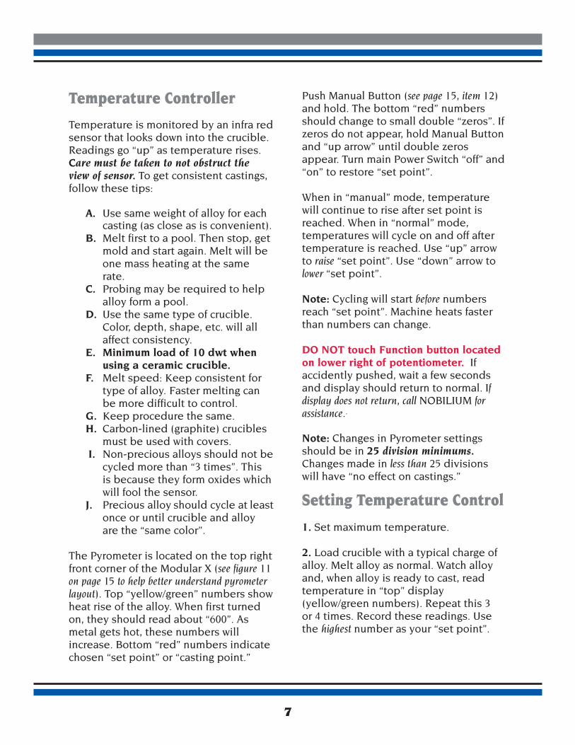
Temperature Controller
Temperature is monitored by an infra redsensor that looks down into the crucible.Readings go “up” as temperature rises.Care must be taken to not obstruct the view of sensor. To get consistent castings,follow these tips:
A. Use same weight of alloy for each casting (as close as is convenient). B. Melt first to a pool. Then stop, get mold and start again. Melt will be one mass heating at the same rate. C. Probing may be required to help alloy form a pool. D. Use the same type of crucible. Color, depth, shape, etc. will all affect consistency. E. Minimum load of 10 dwt when using a ceramic crucible. F. Melt speed: Keep consistent for type of alloy. Faster melting can be more difficult to control. G. Keep procedure the same. H. Carbon-lined (graphite) crucibles must be used with covers.
I. Non-precious alloys should not be cycled more than “3 times”. This is because they form oxides which will fool the sensor. J. Precious alloy should cycle at least once or until crucible and alloy are the “same color”.
The Pyrometer is located on the top rightfront corner of the Modular X (see figure 11on page 15 to help better understand pyrometerlayout). Top “yellow/green” numbers showheat rise of the alloy. When first turnedon, they should read about “600”. Asmetal gets hot, these numbers willincrease. Bottom “red” numbers indicatechosen “set point” or “casting point.”
Push Manual Button (see page 15, item 12)and hold. The bottom “red” numbersshould change to small double “zeros”. Ifzeros do not appear, hold Manual Buttonand “up arrow” until double zerosappear. Turn main Power Switch “off” and“on” to restore “set point”.
When in “manual” mode, temperaturewill continue to rise after set point isreached. When in “normal” mode, temperatures will cycle on and off aftertemperature is reached. Use “up” arrowto raise “set point”. Use “down” arrow tolower “set point”.
Note: Cycling will start before numbersreach “set point”. Machine heats fasterthan numbers can change.
DO NOT touch Function button locatedon lower right of potentiometer. If accidently pushed, wait a few secondsand display should return to normal. Ifdisplay does not return, call NOBILIUM forassistance..
Note: Changes in Pyrometer settingsshould be in 25 division minimums.Changes made in less than 25 divisionswill have “no effect on castings.”
Setting Temperature Control
1. Set maximum temperature.
2. Load crucible with a typical charge ofalloy. Melt alloy as normal. Watch alloyand, when alloy is ready to cast, readtemperature in “top” display (yellow/green numbers). Repeat this 3 or 4 times. Record these readings. Usethe highest number as your “set point”.
7
3. Push “up” or “down” arrows to adjust“set point”.
4. Try a couple of castings to checkresults. Remember, a change of 25 divisionsis needed to have an affect.
5. Once set, the Modular X will alwayscycle at that “set point”.
6. To override cycle, eye must be in“manual” mode.
Note: It is not good to cycle non-preciousalloys too often. They tend to build oxiderapidly which will cause inaccurate temperature readings.
Non-Precious AlloysMelted in Ceramic or Green/Tan Wash Lined Crucibles
1. Leave Pyrometer in the “normal” casting mode. Melt will cycle “on” and“off” when “set point” is reached (semi-automatic mode).
2. Load crucible with a typical charge ofalloy.
3. Semi-Automatic Melt Mode: A. Choose “set point” that is best suitable for your alloy. Selecting
a “set point” may be a trial and error process. B. Once the “set point” is reached, cast alloy by dropping coil firmly to initiate spin.
4. Manual Melt Mode: Visit our websitefor video on when to cast non-preciousalloy.
A. Watch alloy melt. Alloy will turn orange and slump. As the alloy continues to melt and becomes brighter, the “center” or “tip” of the ingots or mass will still have a darker hue. This is known as “shadow.” B. Observe shadow disappearance, wait approximately 4 to 5 seconds (one thousand one, one thousand two, one thousand three, etc.) and cast alloy by dropping the coil firmly to initiate spin.
5. Align crucible over the coil, raise and lock.
6. Remove casting ring.
Precious AlloysMelted in Carbon-Lined (Graphite) Crucibles
1. Leave Pyrometer in “normal” castingmode. Melt will cycle on and off when“set point” is reached.
2. Load crucible with a typical charge ofalloy. Put cover on crucible with cut-outto the rear.
3. Heat until alloy “balls”.
4. Reduce power to 60%.
5. Watch alloy and, when surface clears,read top numbers.
6. Continue melting. When surface startsto “roll”, read top numbers. Stop melt.
7. “Casting point” will be between thesetwo readings.
8
8. Use the high reading as the “startingpoint”. Set Temperature.
9. Start melt. When temperature “setpoint” is reached, the Modular X shouldbe allowed to cycle at least 3 times toassure uniform temperature. Alloy andliner should be the “same color”.
10. Cast alloy by dropping coil firmly.
11. Align crucible over coil. Raise andlock coil.
12. Remove casting ring.
13. Deflask and check casting. You cannow raise or lower temperature to finetune the process.
High-Palladium AlloysMelted in Ceramic Crucibles
Note: High palladium alloys melt veryquickly. Use a lower setting on Melt SwitchPotentiometer such as 20 or 30.
1. Set to maximum temperature reading.
2. Load crucible with a typical charge ofalloy. Melt the way you normally wouldwith non-precious alloys.
3. Watch alloy. First it will “slump”, then it will come together and “ball”. At thispoint, it may or may not clear. Shortlyafter this, it will “smoke”. You shouldread temperature immediately.
4. You should cast just before the smokeoccurs.
5. Push “up” or “down” arrows to set the“set point” as determined in step 3.
6. Try a casting at this setting.
7. Change temperature up or down tozero. Changes must be made in 25 pointdivisions to be effective.
Modular X Crucible Selection
Our crucibles are the finest available.We have a selection that covers most ofall your casting needs. Below are somethings to consider when selecting a crucible and tips on proper crucible handling.
1. Consult with the manufacturer of thealloy that you are using, to determine theoptimal crucible.
2. Cracking crucibles is usually the resultof “improper loading”. A solid metalbridge from one insidewall of the crucibleto the other is usually the cause. Themetal heats, expands and pushes thewalls out.
3. Most high-palladium and chrome-cobalt alloys wet the walls of the crucible and “stick”. Because of this, it may not be wise to use an expensivelined crucible.
4. DO NOT allow the crucibles tobecome contaminated. It can drasticallyreduce their life and may contaminatethe alloy.
5. When hot, the crucibles are more brittle.Great care should always be takenwhen probing alloy, moving the crucibleand removing the oxide shell.
6. DO NOT use any flux in Modular 4 or Modular X crucibles!
7. Remove prior oxide shell beforebeginning a new melt.
9
10
Ticonium Ti-CrucibleP/N 65046
Ti-Crucible w/GreenLining:The best cruciblefor melting nickel-chrome alloys. Can beused with Ticonium andother nickel-chrome,non-precious alloys.Also may be used for high-palladium alloys.
Modular 4 CrucibleP/N 4114
Modular 4 “Unlined”Crucible:Good forchrome-cobalt andhigh-palladium alloys.Will also work with nickel-chrome. Can beused with high-fusinggolds.
Carbon-Lined CrucibleP/N 4116
Carbon-Lined Crucible:Good for low-fusinggolds (melt under 2000°F/1093°C).
Unlined CeramicP/N 2004MP4
Unlined CeramicCruicbleGood for chrome-cobaltand high-palladiumalloys. Will also workwith nickel-chrome. Can be used with high-fusing golds.2000°F/1093°C).
Carbide CrucibleP/N 2004MP5
Unlined CarbideCrucible:Good for low-fusinggolds (melt under 2000°F/1093°C).
Modular 4 CrucibleP/N 4115
Modular 4 Cruciblew/Tan Lining:The bestcrucible for chrome-cobalt alloy. The tan lining resists metaladhesion and attack by most alloys. Verygood for nickel-chromeand high-palladiumalloys. Can be used with high-fusing porcelain gold.
Recomended Crucibles for Modular X Regular Capacity
Recomended Crucibles for Modular X Large Capacity
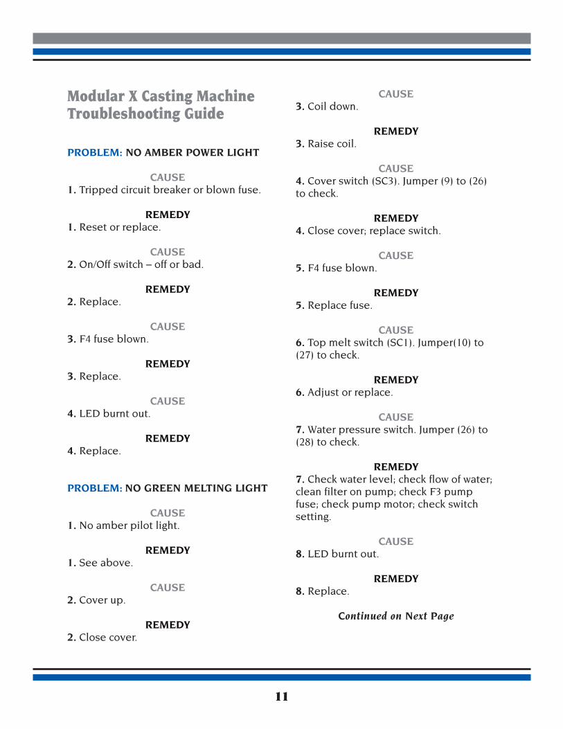
Modular X Casting MachineTroubleshooting Guide
PROBLEM: NO AMBER POWER LIGHT
CAUSE1. Tripped circuit breaker or blown fuse.
REMEDY1. Reset or replace.
CAUSE2. On/Off switch – off or bad.
REMEDY2. Replace.
CAUSE3. F4 fuse blown.
REMEDY3. Replace.
CAUSE4. LED burnt out.
REMEDY4. Replace.
PROBLEM: NO GREEN MELTING LIGHT
CAUSE1. No amber pilot light.
REMEDY1. See above.
CAUSE2. Cover up.
REMEDY2. Close cover.
CAUSE3. Coil down.
REMEDY3. Raise coil.
CAUSE4. Cover switch (SC3). Jumper (9) to (26)to check.
REMEDY4. Close cover; replace switch.
CAUSE5. F4 fuse blown.
REMEDY5. Replace fuse.
CAUSE6. Top melt switch (SC1). Jumper(10) to(27) to check.
REMEDY6. Adjust or replace.
CAUSE7. Water pressure switch. Jumper (26) to(28) to check.
REMEDY7. Check water level; check flow of water;clean filter on pump; check F3 pumpfuse; check pump motor; check switchsetting.
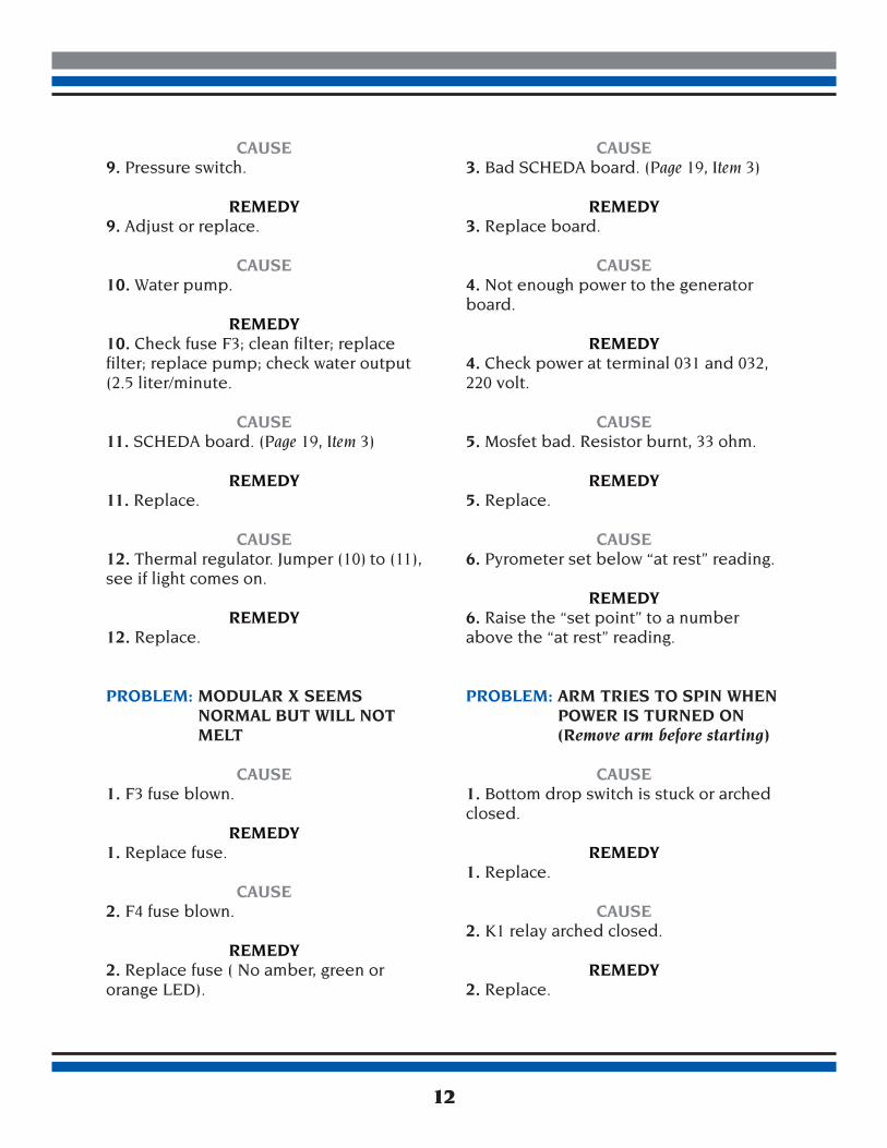
CAUSE12. Thermal regulator. Jumper (10) to (11),see if light comes on.
REMEDY12. Replace.
PROBLEM: MODULAR X SEEMS NORMAL BUT WILL NOTMELT
CAUSE1. F3 fuse blown.
REMEDY1. Replace fuse.
CAUSE2. F4 fuse blown.
REMEDY2. Replace fuse ( No amber, green ororange LED).
CAUSE3. Bad SCHEDA board. (Page 19, Item 3)
REMEDY3. Replace board.
CAUSE4. Not enough power to the generatorboard.
REMEDY4. Check power at terminal 031 and 032,220 volt.
CAUSE5. Mosfet bad. Resistor burnt, 33 ohm.
REMEDY5. Replace.
CAUSE6. Pyrometer set below “at rest” reading.
REMEDY6. Raise the “set point” to a numberabove the “at rest” reading.
PROBLEM: ARM TRIES TO SPIN WHEN POWER IS TURNED ON(Remove arm before starting)
CAUSE1. Bottom drop switch is stuck or archedclosed.
REMEDY1. Replace.
CAUSE2. K1 relay arched closed.
REMEDY2. Replace.
12
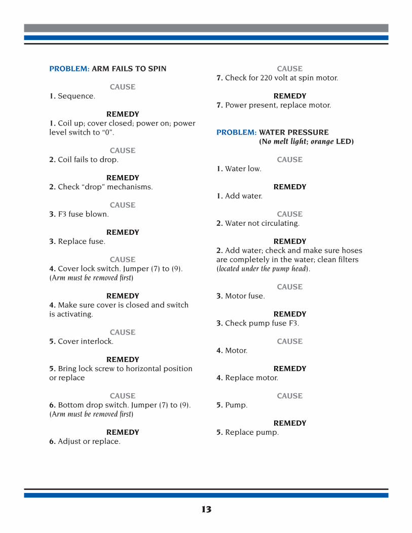
PROBLEM: ARM FAILS TO SPIN
CAUSE1. Sequence.
REMEDY1. Coil up; cover closed; power on; powerlevel switch to “0”.
CAUSE2. Coil fails to drop.
REMEDY2. Check “drop” mechanisms.
CAUSE3. F3 fuse blown.
REMEDY3. Replace fuse.
CAUSE4. Cover lock switch. Jumper (7) to (9).(Arm must be removed first)
REMEDY4. Make sure cover is closed and switchis activating.
CAUSE5. Cover interlock.
REMEDY5. Bring lock screw to horizontal positionor replace
CAUSE6. Bottom drop switch. Jumper (7) to (9). (Arm must be removed first)
REMEDY6. Adjust or replace.
CAUSE7. Check for 220 volt at spin motor.
REMEDY7. Power present, replace motor.
PROBLEM: WATER PRESSURE(No melt light; orange LED)
CAUSE1. Water low.
REMEDY1. Add water.
CAUSE2. Water not circulating.
REMEDY2. Add water; check and make sure hosesare completely in the water; clean filters(located under the pump head).
CAUSE3. Motor fuse.
REMEDY3. Check pump fuse F3.
CAUSE4. Motor.
REMEDY4. Replace motor.
CAUSE5. Pump.
REMEDY5. Replace pump.
13
CAUSE6. Pressure switch.
REMEDY6. Adjust or replace.
CAUSE7. Green LED “on” and orange LED “off”.
REMEDY7. Water too hot. Must wait for themachine and water to cool.
PROBLEM: INCREASED MELT TIME
CAUSE1. Low line voltage.
REMEDY1. Check line voltage, must be 208 voltminimum. Outside boost transformermay be necessary.
PROBLEM: THERMAL REGULATORDOES NOT FUNCTION
CAUSE1. Machine will not melt on the automaticsetting.
REMEDY1. Temperature or “set” point too low.Must be over 1650°F (900°C)
14
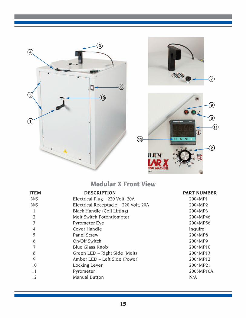
Modular X Front ViewITEM DESCRIPTION PART NUMBERN/S Electrical Plug – 220 Volt, 20A 2004MP1N/S Electrical Receptacle – 220 Volt, 20A 2004MP2 1 Black Handle (Coil Lifting) 2004MP3 2 Melt Switch Potentiometer 2004MP46 3 Pyrometer Eye 2004MP56 4 Cover Handle Inquire 5 Panel Screw 2004MP8 6 On/Off Switch 2004MP9 7 Blue Glass Knob 2004MP10 8 Green LED – Right Side (Melt) 2004MP13 9 Amber LED – Left Side (Power) 2004MP12 10 Locking Lever 2004MP21 11 Pyrometer 2005MP10A 12 Manual Button N/A
15
1
5
43
67
9
8
2
10
11
12
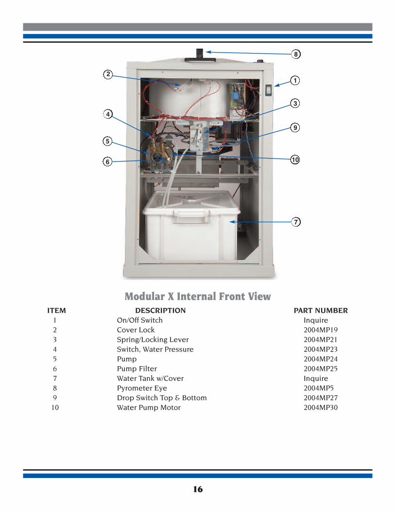
Modular X Internal Front ViewITEM DESCRIPTION PART NUMBER 1 On/Off Switch Inquire 2 Cover Lock 2004MP19 3 Spring/Locking Lever 2004MP21 4 Switch, Water Pressure 2004MP23 5 Pump 2004MP24 6 Pump Filter 2004MP25 7 Water Tank w/Cover Inquire 8 Pyrometer Eye 2004MP5 9 Drop Switch Top & Bottom 2004MP27 10 Water Pump Motor 2004MP30
16
6
5
34
2
8
1
9
10
7
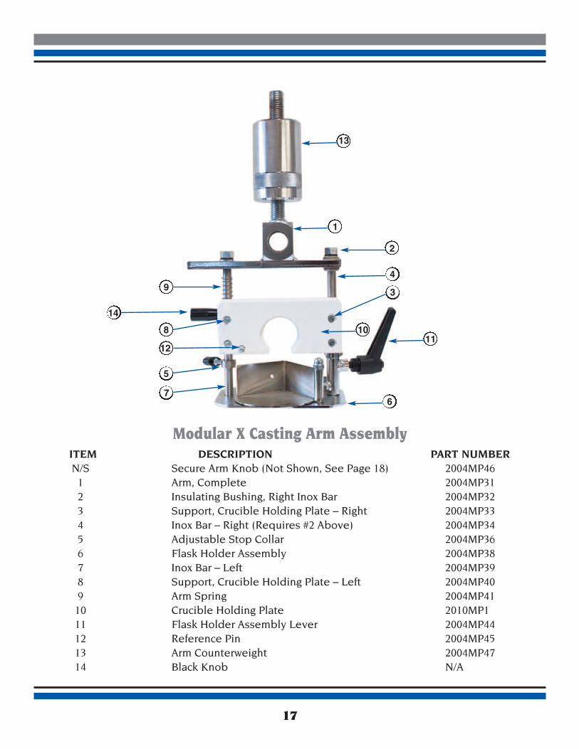
Modular X Casting Arm AssemblyITEM DESCRIPTION PART NUMBERN/S Secure Arm Knob (Not Shown, See Page 18) 2004MP461 Arm, Complete 2004MP31
2 Insulating Bushing, Right Inox Bar 2004MP32 3 Support, Crucible Holding Plate – Right 2004MP33 4 Inox Bar – Right (Requires #2 Above) 2004MP34 5 Adjustable Stop Collar 2004MP36 6 Flask Holder Assembly 2004MP38 7 Inox Bar – Left 2004MP39 8 Support, Crucible Holding Plate – Left 2004MP40 9 Arm Spring 2004MP41 10 Crucible Holding Plate 2010MP1 11 Flask Holder Assembly Lever 2004MP44 12 Reference Pin 2004MP45 13 Arm Counterweight 2004MP47 14 Black Knob N/A
17
13
9
12
14
57
8 10
1
11
2
34
6
Modular X Top & Internal ViewsITEM DESCRIPTION PART NUMBER 1 Arm Counterweight 2004MP47 2 Ceramic Plate 2004MP48 3 Reference Pin Block 2004MP50 4 Tube, Coil Support – Left 2004MP51 5 Support Plate, Vertical Coil 2004MP52 6 Melting Coil 2010MP3 7 Stop, Crucible Holding Plate 2004MP43 8 Tube, Coil Support – Right 2004MP54 9 Spring, Arm 2004MP41 10 Inox Bar – Left 2004MP39 11 Secure Arm Knob 2004MP46 12 Insulating Bushings 2004MP32 13 Crucible Holding Plate 2010MP1 14 Flask Cradle Assembly 2004MP38
18
10
6
12
27
5
3
14
13 9 11
1
84
Modular X Internal Side ViewITEM DESCRIPTION PART NUMBER 1 K1 Spin Relay 2004MP56 2 K2 Melt Relay 2004MP57 3 Main Control Board (SCHEDA) 2004MP58 4 Motor Starting Group 2004MP59 5 Spin Motor 2004MP60 6 Belt, Spin Motor 2004MP62 7 Generator Board Inquire 8 Fuse F-3, K-2 Relay 2004MP70 9 Fuse F-2, K-1 Relay 2004MP71 10 Fuse F-4, Transformer 2004MP73 11 Fuse Water Pump Motor 2004MP14
19
11
2
3
1
7
6
5
4
89
3
10
Division of CMP Industries LLC413 North Pearl Street • Albany, New York 12207518.434.3147 • 800.833.2343 • www.nobilium.com