32
This manual is to be given to the end user Induction motors for the navy MNI - MNIHS Installation and maintenance 3713 en - 12.2003 / b

This manual is to be given to
the end user
Induction motors for the navy MNI - MNIHS
Installation and maintenance
3713 en - 12.2003 / b
2
INSTALLATION AND MAINTENANCE
Induction motors for the navy
MNI - MNIHS
LEROY-SOMER
3713 en - 12.2003 / b
IMPORTANT
These symbols appear in this document whenever it is important to take special precautions during installation,operation, maintenance or servicing of the motors.
It is essential that electric motors are installed by experienced, qualified and authorised personnel.
In accordance with the main requirements of EEC Directives, the safety of people, animals and property should be ensured whenfitting the motors into machines.
Particular attention should be given to equipotential ground or earthing connections.
The noise level of the machines, measured under standard conditions, conforms to the requirements of the standard and does notexceed the maximum value of 85 dB(A) pressure at 1 metre.
The following preliminary precautions must be taken before working on any stationary device:
• Mains voltage disconnected and no residual voltage present• Careful examination of the causes of the stoppage (jammed transmission - loss of phase - Cut-out due to thermal protection- lack of lubrication, etc.)

3
INSTALLATION AND MAINTENANCE
Induction motors for the navy
MNI - MNIHS
LEROY-SOMER
3713 en - 12.2003 / b
Dear Customer,
You have just acquired a LEROY-SOMER motor, developed for DCN, for use on fighting ships.
This motor has been defined in accordance with STB 05.94 for MNI motors, and SATC 001 for MNI HS motors.It benefits from the experience of one of the largest manufacturers in the world, using state-of-the-art technology in automation,specially selected materials and rigorous quality control. As a result, the certification bodies have awarded our motor factories ISO 9001 - Edition 2000 certification.
We thank you for making this choice, and would ask you to read the contents of this manual.
By observing a few essential rules, you will ensure problem-free operation for many years.
LEROY-SOMER MOTORS
CE CONFORMITY:
Our motors conform to standard EN 60034, and therefore to the Low Voltage Directive 73/23/EEC modified by Directive 93/68,which is demonstrated by their marking with the symbol
NOTE:
LEROY-SOMER reserves the right to modify the characteristics of its products at any time in order to incorporate the latesttechnological developments. The information contained in this document may therefore be changed without notice.
Copyright 2003: LEROY-SOMER
This document is the property of LEROY-SOMER.It may not be reproduced in any form without prior authorisation.
All brands and models have been registered and patents applied for.
INSTALLATION AND MAINTENANCE
Induction motors for the navy
MNI - MNIHS
CONTENTS
LEROY-SOMER
3713 en - 12.2003 / b
4
1 - RECEIPT
1.1 - Identification ....................................................................................................................................... 6
1.2 - Storage............................................................................................................................................... 7
2 - RECOMMENDATIONS FOR ASSEMBLY
2.1 - Checking the insulation ...................................................................................................................... 7
2.2 - Location - ventilation ......................................................................................................................... 8
2.3 - Coupling ............................................................................................................................................ 8
2.4 - Electrical guidelines.......................................................................................................................... 11
2.5 - Mains connection ............................................................................................................................. 13
3 - ROUTINE MAINTENANCE
3.1 - Lubrication........................................................................................................................................ 14
3.2 - Bearing maintenance ....................................................................................................................... 15
4 - PREVENTIVE MAINTENANCE
.......................................................................................................... 16
5 - TROUBLESHOOTING GUIDE
........................................................................................................... 17
6 - CORRECTIVE MAINTENANCE: GENERAL INFORMATION
6.1 - Dismantling the motor ...................................................................................................................... 18
6.2 - Checks before reassembly............................................................................................................... 18
6.3 - Mounting the bearings on the shaft .................................................................................................. 18
6.4 - Reassembling the motor .................................................................................................................. 18
6.5 - Reassembling the terminal box ........................................................................................................ 19
7 - POSITION OF LIFTING RINGS
.......................................................................................................... 19
8 - SPARE PARTS
................................................................................................................................... 20
9 - PROCEDURE FOR DISMANTLING AND REASSEMBLY
9.1 - MNI - MNIHS 80 to 132 motors ........................................................................................................ 22
9.2 - MNI - MNIHS 160 and 180 motors ................................................................................................... 24
9.3 - MNI - MNIHS 200 motors ................................................................................................................. 26
9.4 - MNI - MNIHS 225 M to 280 motors .................................................................................................. 28
9.5 - MNI - MNIHS 315 to 355 LD motors ................................................................................................ 30

5
INSTALLATION AND MAINTENANCE
Induction motors for the navy
MNI - MNIHS
LEROY-SOMER
3713 en - 12.2003 / b
MNI motors range – Extracts from STB 05/94
(1) / Special with flying leads (for fans)
For all motors whose specification does not conform todefinition STB 05/94 from DCN BREST, we have createdNon-Standard (HS) motors - STB - SATC001.
- Power > 55 kW with 4 poles- Power > 37 kW with 2 poles- Power > 11/2.2 kW with 4/8 poles- Power > 3kW with 6 poles- Different number of poles (2/4P)- Different construction (B35 for frame size 132)- Switchgear equipment (drip cover - PTC - heating tapes -
PTO - PTF)- Cable glands differing from drawing 17-060-550
rated outputpower in kw
frame size
2-pole motors
1.1 802.2 904 112
7.5 13218.5 16037 200
4-pole motors
0.75 800.75 80 S (1)1.5 902.2 1002.2 100 S (1)4 112
7.5 13211 16015 16022 18030 20045 22555 250
4/8-pole motors
0.63/0.125 800.63/0.125 80 S (1)2.2/0.55 1002.2/0.55 100 S (1)5.5/1.1 13211/2.2 160
6-pole motors
1.1 903 132
6
INSTALLATION AND MAINTENANCE
Induction motors for the navy
MNI - MNIHS
RECEIPT
LEROY-SOMER
3713 en - 12.2003 / b
1 - RECEIPT
On receipt of your motor, check that it has not suffered anydamage in transit. If there are obvious signs of knocks, contact the carrier (youmay able to claim on their insurance) and after a visual check,turn the motor by hand to detect any malfunction.
1.1 - Identification
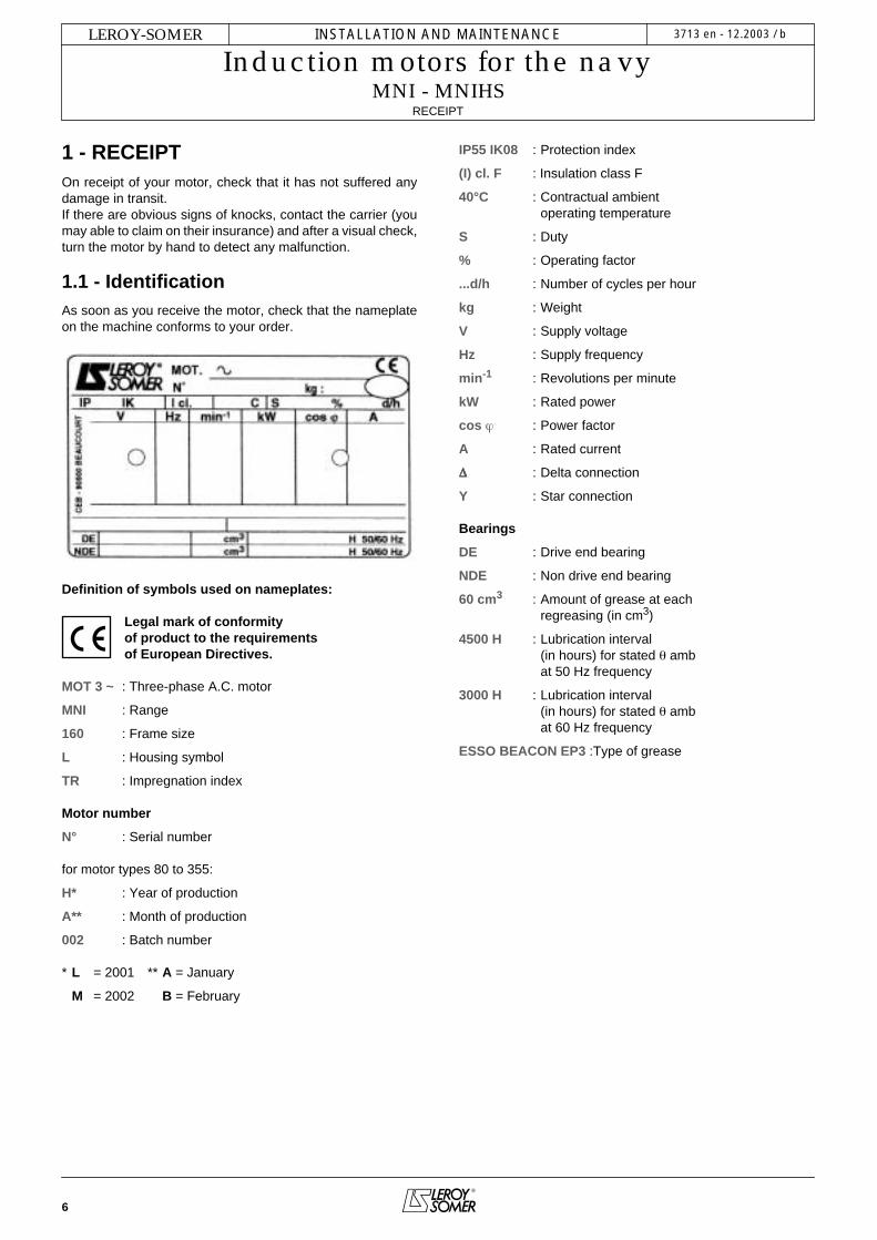
As soon as you receive the motor, check that the nameplateon the machine conforms to your order.
Definition of symbols used on nameplates:
Legal mark of conformityof product to the requirementsof European Directives.
MOT 3 ~
: Three-phase A.C. motor
MNI
: Range
160
: Frame size
L
: Housing symbol
TR
: Impregnation index
Motor number
N°
: Serial number
for motor types 80 to 355:
H*
: Year of production
A**
: Month of production
002
: Batch number
*
L
= 2001 **
A
= January
M
= 2002
B
= February
IP55 IK08
: Protection index
(I) cl. F
: Insulation class F
40°C
: Contractual ambientoperating temperature
S
: Duty
%
: Operating factor
...d/h
: Number of cycles per hour
kg
: Weight
V
: Supply voltage
Hz
: Supply frequency
min
-1
: Revolutions per minute
kW
: Rated power
cos
ϕ
: Power factor
A
: Rated current
∆∆∆∆
: Delta connection
Y
: Star connection
Bearings
DE
: Drive end bearing
NDE
: Non drive end bearing
60 cm
3
: Amount of grease at eachregreasing (in cm
3
)
4500 H
: Lubrication interval(in hours) for stated
θ
ambat 50 Hz frequency
3000 H
: Lubrication interval(in hours) for stated
θ
ambat 60 Hz frequency
ESSO BEACON EP3
:Type of grease

7
INSTALLATION AND MAINTENANCE
Induction motors for the navy
MNI - MNIHS
RECOMMENDATIONS
FOR
ASSEMBLY
LEROY-SOMER
3713 en - 12.2003 / b
1.2 - Storage
Prior to commissioning, machines should be stored: - Away from humidity: in conditions of relative humidity ofmore than 90%, the machine insulation can drop very rapidly,to just above zero at around 100% ; monitor the state of theanti-rust protection on unpainted parts.For very long storage periods the motor can be placed in asealed covering (for example heat-shrunk plastic) containingsachets of desiccant:- Away from frequent significant variations in temperature, toavoid the risk of condensation. During storage the drain plugsmust be removed to allow condensation water to escape.- If the area is subject to vibration, try to reduce the effect ofthis vibration by placing the motor on a damping support(rubber plate or similar) and turn the rotor a fraction of a turnonce a fortnight to prevent the bearing rings from becomingmarked.- Do not discard the rotor locking device (where there areroller bearings).Even if the motor has been stored in the correct conditions,certain checks must be carried out before it is started up:
GreasingBearings which cannot be regreased
Maximum storage: 3 years. After this time, replace thebearings (see section 6.3)
Bearings which can be regreased
Greases used by LEROY-SOMER (see nameplate):grade 3: ESSO BEACON EP3
2 - RECOMMENDATIONS FOR ASSEMBLY
Electric motors are industrial products. They must therefore be installed by qualified,
experienced and authorised personnel. The safety ofpeople, animals and property must be ensured whenfitting the motors into machines (please refer to currentstandards).
2.1 - Checking the insulation
Before starting up the motor, it is advisable tocheck the phase-earth and phase-phase insulation.
This check is essential if the motor has been stored for longerthan 6 months or if it has been kept in a damp atmosphere.This measurement must be carried out using amegohmmeter at 500V D.C. (do not use a magnetoelectricsystem).It is better to carry out an initial test at 30 or 50 volts and if theinsulation is greater than 1 megohm, carry out a second testat 500 volts for 60 seconds. The insulation value must be atleast 10 megohms in cold state.If this value cannot be achieved, or if the motor may havebeen splashed with water or salt spray, or kept for a longperiod in a very humid place or if it is covered withcondensation, it is advisable to dry the stator for 24 hours ina drying oven at a temperature of between 110°C and 120°C.If it is not possible to place the motor in a drying oven:- Switch on the motor, with the rotor locked, at 3-phase A.C.voltage reduced to approximately 10% of the rated voltage,for 12 hours (use an induction regulator or a reductiontransformer with adjustable outlets). For slip-ring motors, thistest should be performed with the rotor short-circuited.- Or supply the 3 phases in series with a D.C. current, with thevoltage at 1 to 2% of the rated voltage (use a D.C. generatorwith independent excitation or batteries for motors of lessthan 22 kW).- NB: The A.C. current must be monitored using a clampammeter, and the D.C. current using a shunt ammeter. Thiscurrent must not exceed 60% of the rated current.It is advisable to place a thermometer in the motor housing: ifthe temperature exceeds 70 °C, reduce the indicated voltageor current by 5% of the original value for every 10° difference.While it is drying, all the motor orifices must be open (terminalbox, drain holes).
Grade 3grease
less than 1 year
The motor can be commissionedwithout regreasing.
more than 1 yearless than 2 years
Regrease before Commissioning, as described in section 3.1
more than 2 years and less than 5
years
Dismantle the bearing- Clean it- Replace the grease completely
more than5 years
Change the bearing- Regrease it completely
Sto
rage
per
iod
M
8
INSTALLATION AND MAINTENANCE
Induction motors for the navy
MNI - MNIHS
RECOMMENDATIONS
FOR
ASSEMBLY
LEROY-SOMER
3713 en - 12.2003 / b
Warning: As the high voltage test has been performed in the factory before despatch, if it
needs be repeated, it should be performed at half thestandard voltage, ie: 1/2 (2U+1000V). Check that thecapacitive effect resulting from the high voltage test iseliminated before connecting the terminals to earth.
Prior to commissioning for all motors:Rotate the motor at no load (no mechanical load)
for 2 to 5 minutes, checking that there is no abnormalnoise. If there is any abnormal noise, see section 5.
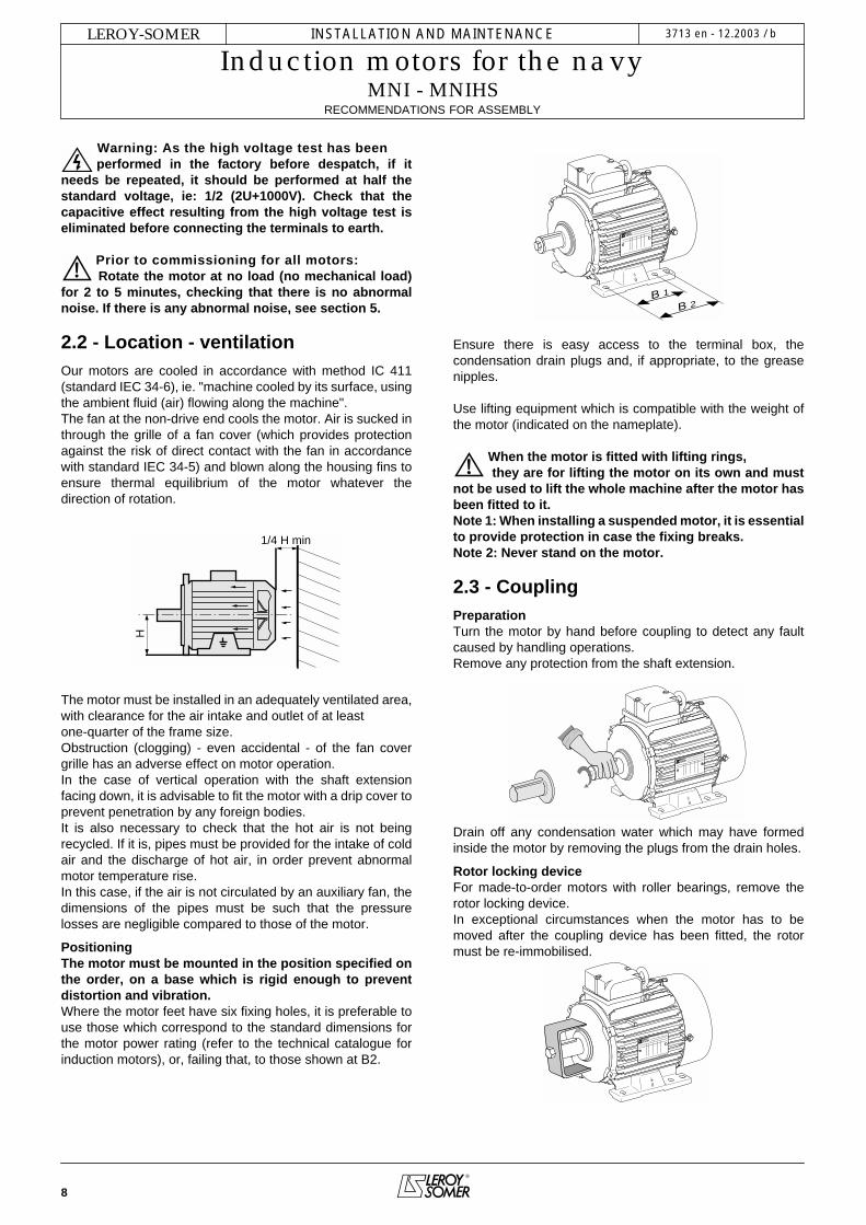
2.2 - Location - ventilation
Our motors are cooled in accordance with method IC 411(standard IEC 34-6), ie. "machine cooled by its surface, usingthe ambient fluid (air) flowing along the machine".The fan at the non-drive end cools the motor. Air is sucked inthrough the grille of a fan cover (which provides protectionagainst the risk of direct contact with the fan in accordancewith standard IEC 34-5) and blown along the housing fins toensure thermal equilibrium of the motor whatever thedirection of rotation.
The motor must be installed in an adequately ventilated area,with clearance for the air intake and outlet of at least one-quarter of the frame size.Obstruction (clogging) - even accidental - of the fan covergrille has an adverse effect on motor operation.In the case of vertical operation with the shaft extensionfacing down, it is advisable to fit the motor with a drip cover toprevent penetration by any foreign bodies.It is also necessary to check that the hot air is not beingrecycled. If it is, pipes must be provided for the intake of coldair and the discharge of hot air, in order prevent abnormalmotor temperature rise.In this case, if the air is not circulated by an auxiliary fan, thedimensions of the pipes must be such that the pressurelosses are negligible compared to those of the motor.
PositioningThe motor must be mounted in the position specified onthe order, on a base which is rigid enough to preventdistortion and vibration.
Where the motor feet have six fixing holes, it is preferable touse those which correspond to the standard dimensions forthe motor power rating (refer to the technical catalogue forinduction motors), or, failing that, to those shown at B2.
Ensure there is easy access to the terminal box, thecondensation drain plugs and, if appropriate, to the greasenipples.
Use lifting equipment which is compatible with the weight ofthe motor (indicated on the nameplate).
When the motor is fitted with lifting rings, they are for lifting the motor on its own and must
not be used to lift the whole machine after the motor hasbeen fitted to it.Note 1: When installing a suspended motor, it is essentialto provide protection in case the fixing breaks.Note 2: Never stand on the motor.
2.3 - Coupling
Preparation
Turn the motor by hand before coupling to detect any faultcaused by handling operations.Remove any protection from the shaft extension.
Drain off any condensation water which may have formedinside the motor by removing the plugs from the drain holes.
Rotor locking device
For made-to-order motors with roller bearings, remove therotor locking device.In exceptional circumstances when the motor has to bemoved after the coupling device has been fitted, the rotormust be re-immobilised.
1/4 H min
H
B 2B 1

9
INSTALLATION AND MAINTENANCE
Induction motors for the navy
MNI - MNIHS
RECOMMENDATIONS
FOR ASSEMBLY
LEROY-SOMER 3713 en - 12.2003 / b
BalancingRotating machines are balanced in accordance with standardISO 8821:- Half-key when the shaft extension is marked H- Full key when the shaft extension is marked F (FAPMO)and any coupling element (pulley, coupling sleeve, slip-ring,etc) must therefore be balanced accordingly.
PrecautionsAll measures must be taken to ensure protection against therisks which arise when there are rotating parts (couplingsleeve, pulley, belt etc).
If a motor is started up without a coupling devicehaving been fitted, carefully immobilise the key in
its location.
Beware of backdriving when the motor is switched off. Theappropriate precautions must be taken:- for pumps, a non-return valve must be installed.- for mechanical devices, install a backstop or a holding brake.- etc.
Tolerances and adjustmentsThe standard tolerances are applicable to the mechanicalcharacteristics given in our catalogues. They comply fully withthe requirements of IEC standard 72-1.- Users must adhere strictly to the instructions provided by thetransmission device supplier. - Avoid impacts which could damage the bearings.Use a spanner and the tapped hole of the shaft extension witha special lubricant (eg. molykote grease) to make it easier tofit the coupling.
The hub of the transmission device must be:- Fully in contact with the shoulder of the shaft or, if this ismissing, against the metal stop ring which forms a labyrinthseal and thus locks the bearing in place (do not crush theseal).- Longer than the shaft extension (2 to 3 mm) so that it can betightened using a screw and washer. If it is not, a spacer ringmust be inserted without cutting the key (if this ring is large, itmust be balanced).
Resting Restingon the shoulder of the shaft on the stop ring
The inertia flywheels device must not be mounted directlyonto the shaft extension, but installed between end shield anddevice using a coupling.
Direct connection onto the machineWhen the mobile device (pump or fan turbine) is mounteddirectly on the motor shaft extension, check that this device isperfectly balanced and that the radial force and the axialthrust are within the limits indicated in the catalogue for thebearing withstand.
Direct connection using a flexible couplingThe coupling must be chosen taking into account the ratedtorque to be transmitted and the safety factor according to thestarting conditions for the electric motor.
The machines must be carefully aligned, so that any lack ofconcentricity and parallelism in the two parts of the couplingis compatible with the recommendations of the couplingmanufacturer.
Both parts of the coupling should be provisionally assembledto make it easier to alter their relative position.
Adjust the parallelism of both shafts using a gauge. Measurethe distance between the two coupling surfaces at one pointon the circumference. Rotate them 90°, 180° and 270° inrelation to this initial position, and measure each time. Thedifference between the two extreme values of dimension "x"must not exceed 0.05 mm for standard couplings.
To perfect this adjustment and at the same time check theconcentricity of the two shafts, fit 2 gauges as shown in thediagram and slowly turn both shafts.The differences registered by either shaft will indicate theneed for an axial or radial adjustment if the differenceexceeds 0.05 mm.
Direct connection using a rigid couplingThe two shafts must be aligned in order to keep to thetolerances given by the coupling sleeve manufacturer.Maintain the minimum distance between the two shaftextensions to allow for expansion of the motor shaft and theload shaft.
Ø (mm) A (mm)min.
9 to 55 1
60 1.5
65 1.5
75 2
80 2
x
�
�

10
INSTALLATION AND MAINTENANCE
Induction motors for the navyMNI - MNIHS
RECOMMENDATIONS FOR ASSEMBLY
LEROY-SOMER 3713 en - 12.2003 / b
Transmission via belt pulleysThe user can choose the diameter of the pulleys.Cast iron pulleys with a diameter greater than 315 are notrecommended for rotation speeds of 3000 min-1.Flat belts cannot be used for rotation speeds of 3000 min-1 ormore.
Positioning the beltsSo that the belts can be correctly positioned, allow for apossible adjustment of approximately 3% with respect to thecalculated distance E.Force must never be used when fitting the belts.For notched belts, position the notches in the pulley grooves.
Aligning the pulleysCheck that the motor shaft is totally parallel to that of thereceiving pulley.
Protect all rotating devices beforepower-up.
Adjusting the tension of the beltsThe tension of the belts must be adjusted very carefully inaccordance with the recommendations of the belt supplierand the calculations made when the product was specified.Reminder:- Tension too great = unnecessary force on the end shieldswhich could lead to premature wear of the bearing unit (endshield-bearings) and eventually break the shaft.- Too little tension = vibration (wearing of the bearing unit).
Fixed distance between centres: Place a belt tensioning pulley on the slack side of the belts:- Smooth pulley on the outside of the belt- Grooved pulley on the inside of the belts when using V-belts.
Adjustable distance between centres:The motor is generally mounted on slide rails, which enablesoptimum adjustment of the pulley alignment and the belttension. Place the slide rails on a totally horizontal baseplate.The lengthways position of the slide rails is determined by thelength of the belt, and the crossways position by the pulley ofthe machine being driven.Mount the slide rails firmly with the tension screws in thedirection shown in the diagram (the slide rail screw on the beltside between the motor and the machine being driven).Fix the slide rails onto the baseplate and adjust the belttension as before.
E
Tension screw
Tension screw
Option: Standard slide rails (conforming to standard NFC 51-105) These steel slide rails are supplied with tension screws and the 4 nuts and bolts for fixing the motor on the slide rails, but the fixingbolts for the slide rails are not supplied.
MOTOR SLIDE RAIL DIMENSIONS WEIGHT OF PAIR FRAME SIZE TYPE A E H K L X Y Z Ø J SLIDE RAILS (kg)
80 and 90 G 90/8 PM 355 395 40 2.5 50 324 264 294 13 3100, 112 and 132 G 132/10 PM 480 530 49.5 7 60 442 368 405 15 6
160 and 180 G 180/12 PM 630 686 60.5 7 75 575 475 525 19 11200 and 225 G 225/16 PF 800 864 75 28.5 90 - 623 698 24 16250 and 280 G 280/20 PF 1000 1072 100 35 112 - 764 864 30 36315 and 355 G 355/24 PF 1250 1330 125 36 130 - 946 1064 30 60
�
�
�
�
�
�
�
�
�

11
INSTALLATION AND MAINTENANCE
Induction motors for the navyMNI - MNIHS
RECOMMENDATIONS FOR ASSEMBLY
LEROY-SOMER 3713 en - 12.2003 / b
2.4 - Electrical guidelines
2.4.1 - Minimizing motor starting problems
In order to protect the installation, all significant temperaturerises in the cabling conduits must be prevented, whileensuring that the protection devices are not triggered duringstarting.Operating problems in other equipment connected to thesame supply are due to the voltage drop caused by thecurrent demand on starting - many times greater than thecurrent absorbed by the motor at full load (approximately 7).See the LEROY-SOMER induction motors technicalcatalogue).Even though the mains supplies increasingly allow D.O.L.starting, the current inrush must be reduced for certaininstallations.Jolt-free operation and soft starting ensure greater ease ofuse and increased service life for the machines being driven.The two essential parameters for starting cage inductionmotors are:- starting torque- starting currentThe starting torque and the resistive torque determine thestarting time.Depending on the load being driven, it is possible to adapt thetorque and the current to the machine starting time and to thepossibilities of the mains power supply.
2.4.2 - Starting times and permissible locked rotor times
The starting times must remain within the limits stated belowon condition that the number of starts per hour is 6 or less.Three successive cold starts and two consecutive warmstarts are allowed.
Permissible motor starting times as a function of theratio
2.4.3 - Earthing (see section 2.5.4)
2.4.4 - Motor protection devices
2.4.4.1 - On-line protection
Adjusting the thermal protectionIt should be adjusted to the value of the current read on themotor nameplate for the connected mains voltage andfrequency.
Thermal magnetic protectionThe motors must be protected by a thermal magnetic devicelocated between the isolating switch and the motor. Theseprotection devices provide total protection of the motoragainst non-transient overloads. This device can be accompanied by fused circuit-breakers.
Built-in direct thermal protection - MNIHSFor low rated currents, bimetallic strip-type protection may beused. The line current passes through the strip, which shutsdown or restores the supply circuit as necessary. The designof this type of protection allows for manual or automatic reset.
2.4.4.2 - Built-in indirect thermal protection - MNIHS
The motors can be equipped with optional heat sensors.These sensors can be used to monitor temperature changesat “hot spots”:- overload detection- cooling check- monitoring strategic points for maintenance of the installationIt must be emphasized that sensors cannot be used to carryout direct adjustments to the motor operating cycles.
3 4 5 7 10 153
4
5
6
789
10
15
20
ID_IN
St

12
INSTALLATION AND MAINTENANCE
Induction motors for the navyMNI - MNIHS
RECOMMENDATIONS FOR ASSEMBLY
LEROY-SOMER 3713 en - 12.2003 / b
- NRT: nominal running temperature- The NRTs are chosen according to the position of the sensor in the motor and the temperature rise class.* The number of devices affects the protection of the windings.
Type Operatingprinciple
Operatingcurve
Cut-off (A) Protection provided MountingNumber of devices*
Normally closedthermostat
PTO
bimetallic strip, indirectly heated, with normally closed (NC)
contact
2.5 at 250 Vwith cos ϕ 0.4
general surveillancefor non-transient
overloads
Mounting in controlcircuit
2 or 3 in series
Normally openthermostat
PTF
bimetallic strip, indirectly heated, with normally open (NO)
contact2.5 at 250 V
with cos ϕ 0.4
general surveillancefor non-transient
overloads
Mounting in control circuit
2 or 3 in parallel
Positive temperaturecoefficientthermistor
PTC
Variable non-linearresistor with
indirect heating 0 general surveillancefor transient overloads
Mounted with associated relay in control
circuit
3 in series
Thermocouples T (T<150 °C)
Copper Constantan K (T<1000 °C)Copper-nickel
Peltier effect 0continuous surveillanceat hot spots
Mounting in switchboards with associated reader
(or recorder)
1 per hot spot
Platinum resistance thermometer
PT 100
Variable linearresistor
indirect heating0
high accuracycontinuous surveillance
at key hot spots
Mounting in switchboards with associated reader
(or recorder)
1 per hot spot
�
� ���
T
�
� ���
T
R
TNF
T
V
T
R
T
Alarm and early warningAll protective equipment may be backed up by another typeof protection (with different NRTs): the first device will then actas an early warning (light or sound signals given withoutshutting down the power circuits), and the second device willbe the alarm (shutting down the power circuits).
Warning: Depending on the type of protection, the motor may remain powered up. Ensure that the
mains supply is disconnected before any work is carriedout in the terminal box or in the cabinet.
Protection against condensation: Space heatersIdentification: 1 red labelA glass fibre flexible resistor is fixed on 1 or 2 coil end turns.This resistor heats the machines when stopped and thusprevents condensation inside the machines. Power supply: 230V single-phase unless otherwise specifiedby the customer.If the drain plugs at the bottom of the motor have not beenremoved at the time of installation, they must be openedapproximately every 6 months.
Warning: Check that the space heaters areswitched off before any work is carried out in the
terminal box or in the cabinet.

13
INSTALLATION AND MAINTENANCE
Induction motors for the navyMNI - MNIHS
RECOMMENDATIONS FOR ASSEMBLY
LEROY-SOMER 3713 en - 12.2003 / b
2.5 - Mains connection
2.5.1 - Terminal box
Placed as standard on the top of the motor near the drive end,the terminal box has IP 55 protection and is fitted with a cablegland.Warning: The position of the terminal box cannot be easilymodified, even with flanged motors, as the condensationdrain holes must be at the bottom.
BVLE cable glandThe standard position of the cable gland is at the back, seenfrom the drive end.
A cable gland must never open upwards.
Check that the incoming cables have bends of such a radiusas to prevent water from running into the cable gland.
2.5.2 - Wiring diagram
All motors are supplied with a wiring diagram in the terminalbox*.The connections are made with MAF terminals.
Particular attention must be paid to theinformation on the nameplate in order to choose
the correct type of connection for the supply voltage.
2.5.3 - Direction of rotation
When the motor is running in U1, V1, W1 or 1U, 1V, 1W froma direct mains supply L1, L2, L3, it turns clockwise when seenfrom the drive shaft end.If 2 phases of the power supply are changed over, the motorwill rotate anti-clockwise (the motor should be checked toensure that it has been designed for both directions ofrotation). Warning: motor with backstop: starting in the wrong directiondestroys the backstop (see arrow on motor housing).If the motor is fitted with accessories (thermal protection orspace heater), these should be connected on a terminalblock.
Terminal block
HL 105 modules
* If required, this diagram should be obtained from thesupplier, specifying the motor type and number (shown on themotor nameplate).Type of
BVLEMin. cable Ø
(mm)Max. cable Ø (mm)
1 8 13.5
2 10 16.5
3 13 20.5
4 19.5 25
5 23 29
6 30 38
7 38 44.5
9 46 53
A Standardposition
2 4
1
3
Standardposition
AOutput
D
B
E
C
FG
K
H
L
J
MN
S
P
T
R
U
InputThermistors
Heatingtapes
Output
Input
14
INSTALLATION AND MAINTENANCE
Induction motors for the navyMNI - MNIHS
ROUTINE MAINTENANCE
LEROY-SOMER 3713 en - 12.2003 / b
2.5.4 - Earth terminal
This is situated inside the terminal box and on the housing.
It is indicated by the symbol:
Earthing the motor is compulsory, and must beperformed in accordance with current regulations
(protection of workers).
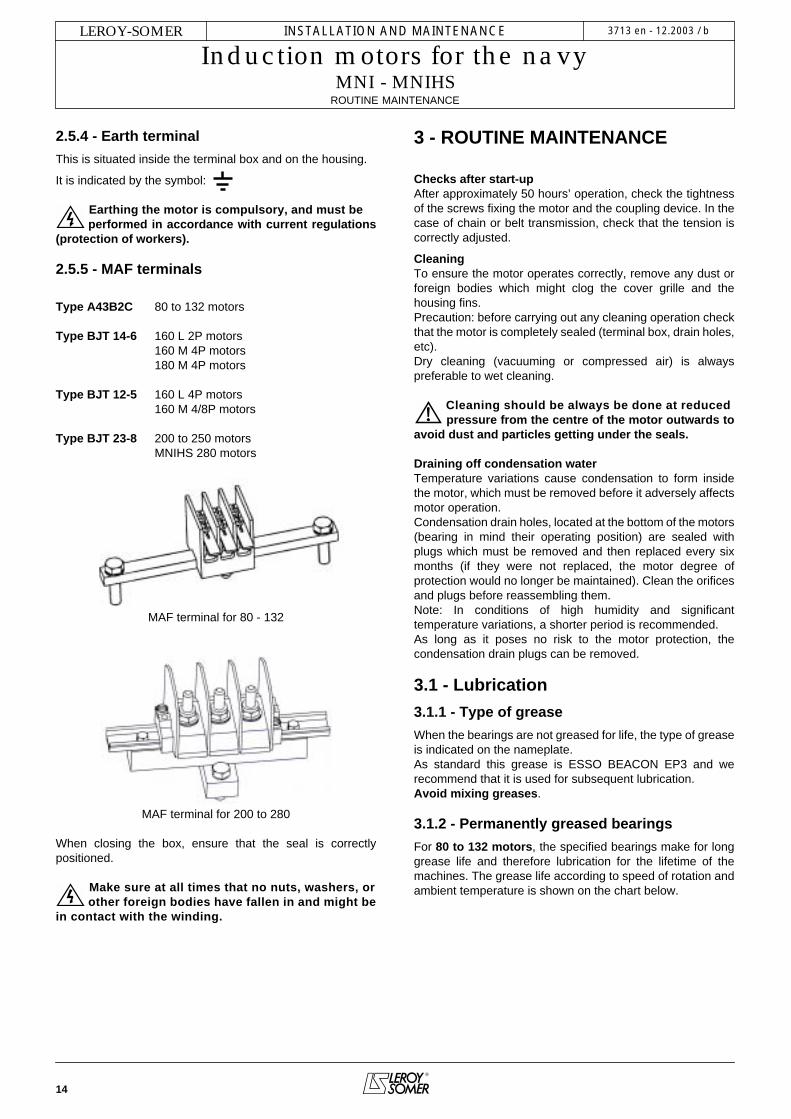
2.5.5 - MAF terminals
Type A43B2C 80 to 132 motors
Type BJT 14-6 160 L 2P motors160 M 4P motors180 M 4P motors
Type BJT 12-5 160 L 4P motors160 M 4/8P motors
Type BJT 23-8 200 to 250 motorsMNIHS 280 motors
MAF terminal for 80 - 132
MAF terminal for 200 to 280
When closing the box, ensure that the seal is correctlypositioned.
Make sure at all times that no nuts, washers, orother foreign bodies have fallen in and might be
in contact with the winding.
3 - ROUTINE MAINTENANCE
Checks after start-upAfter approximately 50 hours’ operation, check the tightnessof the screws fixing the motor and the coupling device. In thecase of chain or belt transmission, check that the tension iscorrectly adjusted.
CleaningTo ensure the motor operates correctly, remove any dust orforeign bodies which might clog the cover grille and thehousing fins.Precaution: before carrying out any cleaning operation checkthat the motor is completely sealed (terminal box, drain holes,etc).Dry cleaning (vacuuming or compressed air) is alwayspreferable to wet cleaning.
Cleaning should be always be done at reduced pressure from the centre of the motor outwards to
avoid dust and particles getting under the seals.
Draining off condensation waterTemperature variations cause condensation to form insidethe motor, which must be removed before it adversely affectsmotor operation.Condensation drain holes, located at the bottom of the motors(bearing in mind their operating position) are sealed withplugs which must be removed and then replaced every sixmonths (if they were not replaced, the motor degree ofprotection would no longer be maintained). Clean the orificesand plugs before reassembling them.Note: In conditions of high humidity and significanttemperature variations, a shorter period is recommended.As long as it poses no risk to the motor protection, thecondensation drain plugs can be removed.
3.1 - Lubrication
3.1.1 - Type of grease
When the bearings are not greased for life, the type of greaseis indicated on the nameplate.As standard this grease is ESSO BEACON EP3 and werecommend that it is used for subsequent lubrication.Avoid mixing greases.
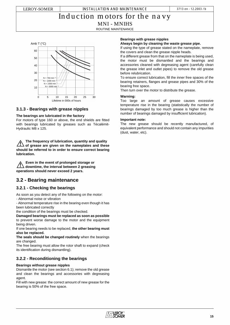
3.1.2 - Permanently greased bearings
For 80 to 132 motors, the specified bearings make for longgrease life and therefore lubrication for the lifetime of themachines. The grease life according to speed of rotation andambient temperature is shown on the chart below.
15
INSTALLATION AND MAINTENANCE
Induction motors for the navyMNI - MNIHS
ROUTINE MAINTENANCE
LEROY-SOMER 3713 en - 12.2003 / b
3.1.3 - Bearings with grease nipples
The bearings are lubricated in the factoryFor motors of type 160 or above, the end shields are fittedwith bearings lubricated by greases such as Técalémit-Hydraulic M8 x 125.
The frequency of lubrication, quantity and qualityof grease are given on the nameplates and these
should be referred to in order to ensure correct bearinglubrication.
Even in the event of prolonged storage ordowntime, the interval between 2 greasing
operations should never exceed 2 years.
3.2 - Bearing maintenance
3.2.1 - Checking the bearings
As soon as you detect any of the following on the motor:- Abnormal noise or vibration- Abnormal temperature rise in the bearing even though it hasbeen lubricated correctlythe condition of the bearings must be checked.Damaged bearings must be replaced as soon as possibleto prevent worse damage to the motor and the equipmentbeing driven.If one bearing needs to be replaced, the other bearing mustalso be replaced.The seals should be changed routinely when the bearingsare changed.The free bearing must allow the rotor shaft to expand (checkits identification during dismantling).
3.2.2 - Reconditioning the bearings
Bearings without grease nipplesDismantle the motor (see section 6.1); remove the old greaseand clean the bearings and accessories with degreasingagent.Fill with new grease: the correct amount of new grease for thebearing is 50% of the free space.
Bearings with grease nipplesAlways begin by cleaning the waste grease pipe.If using the type of grease stated on the nameplate, removethe covers and clean the grease nipple heads.If a different grease from that on the nameplate is being used,the motor must be dismantled and the bearings andaccessories cleaned with degreasing agent (carefully cleanthe grease inlet and outlet pipes) to remove the old greasebefore relubrication.To ensure correct lubrication, fill the inner free spaces of thebearing retainers, flanges and grease pipes and 30% of thebearing free space.Then turn over the motor to distribute the grease.
Warning: Too large an amount of grease causes excessivetemperature rise in the bearing (statistically the number ofbearings damaged by too much grease is higher than thenumber of bearings damaged by insufficient lubrication).
Important note:The new grease should be recently manufactured, ofequivalent performance and should not contain any impurities(dust, water, etc).
10
0
20
30
40
50
60
Amb T (°C)
3010 20
N = 750 min -1
N = 1500 min -1
N = 1000 min -1
5 15 25
N = 3000 min -1
Lifetime in 000s of hours
16
INSTALLATION AND MAINTENANCE
Induction motors for the navyMNI - MNIHS
PREVENTIVE MAINTENANCE
LEROY-SOMER 3713 en - 12.2003 / b
4 - PREVENTIVE MAINTENANCE
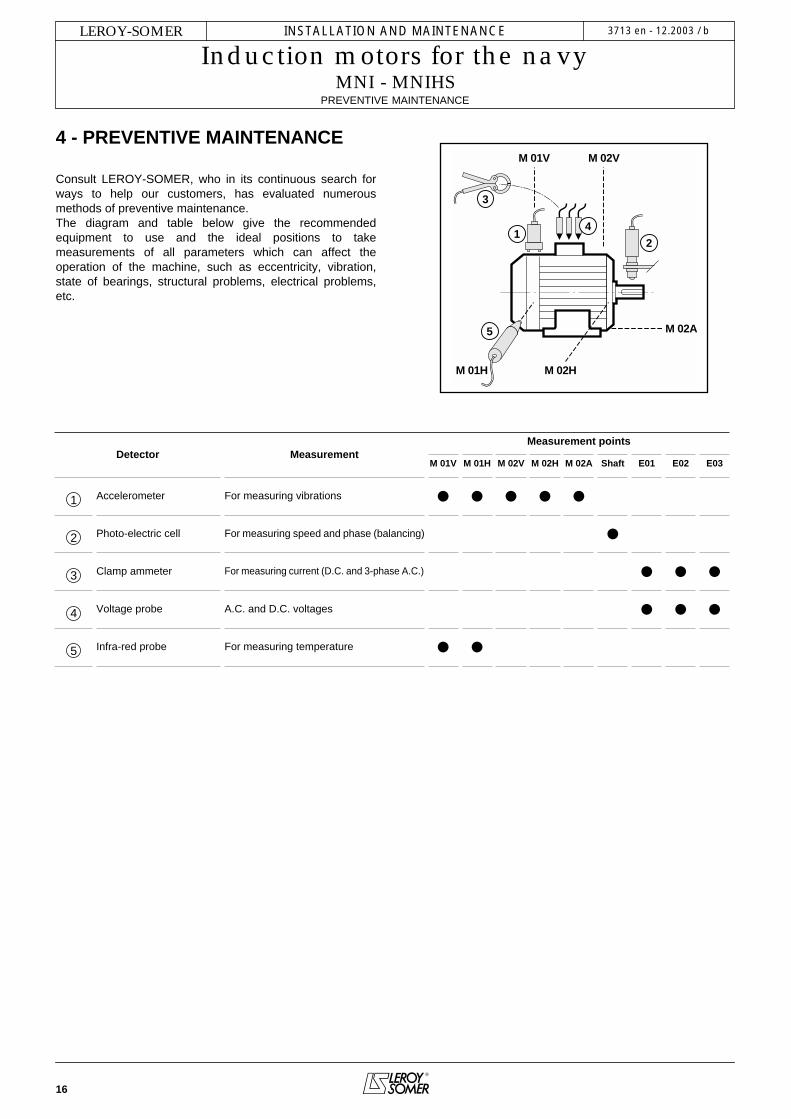
Consult LEROY-SOMER, who in its continuous search forways to help our customers, has evaluated numerousmethods of preventive maintenance.The diagram and table below give the recommendedequipment to use and the ideal positions to takemeasurements of all parameters which can affect theoperation of the machine, such as eccentricity, vibration,state of bearings, structural problems, electrical problems,etc.
M 01V M 02V
M 02A
M 02HM 01H
1
3
4
2
5
Detector MeasurementMeasurement points
M 01V M 01H M 02V M 02H M 02A Shaft E01 E02 E03
1 Accelerometer For measuring vibrations • • • • •2 Photo-electric cell For measuring speed and phase (balancing) •3 Clamp ammeter For measuring current (D.C. and 3-phase A.C.) • • •4 Voltage probe A.C. and D.C. voltages • • •5 Infra-red probe For measuring temperature • •
17
INSTALLATION AND MAINTENANCE
Induction motors for the navyMNI - MNIHS
TROUBLESHOOTING GUIDE
LEROY-SOMER 3713 en - 12.2003 / b
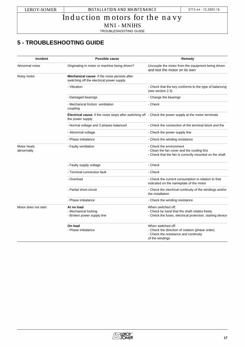
5 - TROUBLESHOOTING GUIDE
Incident Possible cause Remedy
Abnormal noise Originating in motor or machine being driven? Uncouple the motor from the equipment being drivenand test the motor on its own
Noisy motor Mechanical cause: if the noise persists afterswitching off the electrical power supply
- Vibration - Check that the key conforms to the type of balancing (see section 2.3)
- Damaged bearings - Change the bearings
- Mechanical friction: ventilationcoupling
- Check
Electrical cause: if the noise stops after switching off the power supply
- Check the power supply at the motor terminals
- Normal voltage and 3 phases balanced - Check the connection of the terminal block and the
- Abnormal voltage - Check the power supply line
- Phase imbalance - Check the winding resistance
Motor heatsabnormally
- Faulty ventilation - Check the environment- Clean the fan cover and the cooling fins- Check that the fan is correctly mounted on the shaft
- Faulty supply voltage - Check
- Terminal connection fault - Check
- Overload - Check the current consumption in relation to that indicated on the nameplate of the motor
- Partial short-circuit - Check the electrical continuity of the windings and/or the installation
- Phase imbalance - Check the winding resistance
Motor does not start At no load- Mechanical locking- Broken power supply line
When switched off:- Check by hand that the shaft rotates freely- Check the fuses, electrical protection, starting device
On load- Phase imbalance
When switched off:- Check the direction of rotation (phase order)- Check the resistance and continuityof the windings

18
INSTALLATION AND MAINTENANCE
Induction motors for the navyMNI - MNIHS
CORRECTIVE MAINTENANCE: GENERAL
LEROY-SOMER 3713 en - 12.2003 / b
6 - CORRECTIVE MAINTENANCE: GENERAL
Switch off and lock the power supply before any intervention
- Open the terminal box, mark the wires and their positions- Disconnect the power supply wires- Uncouple the motor from the equipment being drivenAlways use an extractor to remove any devices mounted onthe motor shaft extension.
6.1 - Dismantling the motorRefer to the detailed instructions for the relevant motor range(see following pages). It is advisable to identify the shields in relation to the statorand the direction of the fan on the rotor.
6.2 - Checks before reassemblyStator:- Remove all dust from the stator: if the winding needs to be cleaned, an appropriate liquid mustbe used: dielectric and inert on the insulation and the externalfinish.- Check the insulation (see section 2.1) and if necessary, dryit in an oven.- Clean the spigots thoroughly, and remove all traces ofknocks on the mating surfaces if necessary.
Rotor:- Clean and check the bearing running surfaces. If they aredamaged, renew the running surfaces or change the rotor.- Check the condition of the threads, keys and their housings.
End shields:- Clean off any traces of dirt (old grease, accumulated dust,etc.).- Clean the bearing housings and the spigot.- If necessary, apply anti-flash varnish to the insides of theend shields.- Carefully clean the bearing caps and the grease valves (ifthese are fitted on the motor).
6.3 - Mounting the bearings on the shaftThis operation is extremely important, as the slightestindentation of a ball on the bearing tracks would cause noiseand vibration.Lightly lubricate the running surfaces of the shaft.There are a number of ways of mounting the bearingscorrectly:
- Cold state: The bearings must be mounted without anyimpact, using a spanner (do not use a hammer). The forceapplied must not be transferred to the bearing track. Youshould therefore use the internal cage for support (taking carenot to press on the seal shield for sealed bearings).- Hot state: heat the bearing to between 80 and 100°C: in adrying cabinet, an oven or on a heating plate.
(A blowtorch or an oil bath must never be used). Afterdismantling and reassembling a bearing, all the spacesbetween the seals and labyrinth seals must be filled withgrease in order to prevent the entry of dust and the rusting ofmachined parts.See detailed instructions for the relevant motor ranges in thefollowing pages.
6.4 - Reassembling the motorCare must be taken to ensure that the stator is replacedin its original position, so that the stack of laminations iscentred correctly (generally with the terminal box facingforward) and the water drain holes are positioned correctly ifthey are on the housing.
Tightening the tie rodsThese must be tightened diagonally, to the torque indicated(see below).
Tie rod tightening torque
Type Rod/screw Ø Tightening torqueN. m ± 5%
80 M5 4
90 M5 4
100 M5 or M6 4
112 M5 or M6 4
132 M7 10
160 M8 18
180 L M10 25
200 M10 25
225 M M12 44
250 M12 44
280 MNIHS M12 44
315 MNIHS M12 44
1 4
3 2

19
INSTALLATION AND MAINTENANCE
Induction motors for the navyMNI - MNIHS
POSITION OF THE LIFTING RINGS
LEROY-SOMER 3713 en - 12.2003 / b
6.5 - Reassembling the terminal boxReconnect all the power supply wires in accordance with thediagram or markings made before dismantling. To ensure thebox is properly sealed: check that the cable glands on the boxand the cable(s) have been retightened, and ensure that theseal has been correctly positioned before closing. Forterminal boxes equipped with a nozzle (part no. 89 on theexploded views) or/and a cable gland support plate, ensurethat the seal has been correctly positioned before closing.Check that the terminal box components are tightenedcorrectly.
Note: It is advisable to test the motor at no load- If necessary, repaint the motor.- Mount the transmission device on the motor shaft extensionand reinstall the motor on the machine to be driven.
7 - POSITION OF THE LIFTING RINGS
Position of the lifting rings for lifting themotor only (not coupled to the machine).
Labour regulations stipulate that all loads over 25 kg must befitted with lifting devices to facilitate handling.The positions of the lifting rings and the minimum dimensionsof the loading bars are given below in order to help withpreparation for handling the motors. If these precautions arenot followed, there is a risk of warping or crushing someequipment such as the terminal box, protective cover or dripcover.
Motors designed for use in a vertical positionmay be delivered on a pallet in the horizontal
position. When the motor is pivoted, the shaft mustunder no circumstances be allowed to touch the ground,as the bearings may be irreparably damaged. Moreover,additional special precautions must be taken, as theintegral motor lifting rings are not designed for pivotingthe motor.
• Horizontal position
Type Horizontal position
A e min. h min. Øt
100 120 200 150 9112 120 200 150 9132 160 200 150 9160 200 160 110 14
180 MR 200 160 110 14180 L 200 260 150 14200 270 260 165 14
225 ST/MT 270 260 150 14225 M 360 265 200 30250 360 380 200 30280 360 380 500 30
315 ST 310 380 500 17315 M/L 360 380 500 23
355 310 380 500 23
�
�
�
� � ��

20
INSTALLATION AND MAINTENANCE
Induction motors for the navyMNI - MNIHS
SPARE PARTS
LEROY-SOMER 3713 en - 12.2003 / b
• Vertical position
View from above Side view
* if the motor is fitted with a drip cover, allow an additional 50to 100 mm to avoid damaging it when the load is swung.
8 - SPARE PARTSWhen ordering spare parts, you must indicate thecomplete motor type, its serial number and theinformation given on the nameplate (see section 1).
Part numbers can be found on the exploded views andtheir descriptions in the parts list (see section 9).
In the case of flange mounted motors, indicate the type offlange and its dimensions (see below).
IM 3001 (IM B35)
IM 3601 (IM B34)
Our extensive network of service centres can dispatchthe necessary parts without delay.
To ensure that our motors operate correctly and safely,we recommend the use of original manufacturer spareparts.
In the event of failure to comply with this advice, themanufacturer cannot be held responsible for anydamage.
Type Vertical position
C E D N ØS e min.* h min.
160 320 200 230 2 14 320 350180 MR 320 200 230 2 14 320 270180 L 390 265 290 2 14 390 320200 410 300 295 2 14 410 450
225 ST/MT 410 300 295 2 14 410 450225 M 480 360 405 4 30 540 350250 480 360 405 4 30 540 350
280 S 480 360 485 4 30 590 550280 M 480 360 585 4 30 590 550315 ST 590 - 590 2 17 630 550315 M/L 695 - 765 2 24 695 550
355 755 - 835 2 24 755 550
�
�� � ��
�
�
�� �
� �
���
� �
�
� �
���
� � �

21
INSTALLATION AND MAINTENANCE
Induction motors for the navyMNI - MNIHS
SPARE PARTS
LEROY-SOMER 3713 en - 12.2003 / b

22
INSTALLATION AND MAINTENANCE
Induction motors for the navyMNI - MNIHS
PROCEDURE FOR DISMANTLING AND REASSEMBLY
LEROY-SOMER 3713 en - 12.2003 / b
9 - PROCEDURE FOR DISMANTLING AND REASSEMBLY
9.1 - MNI - MNIHS 80 to 132 motors
9.1.1 - Dismantling
- Remove the screws (27) and then take off the cover (13).- Pull out the fan (7) using a hub remover or 2 levers (forexample, 2 screwdrivers) diametrically opposed to oneanother, using the shield (6) for support.- Remove the tie rods (14).- Remove the key (21).- Using a wooden mallet, tap the shaft on the fan side in orderto loosen the drive end shield (5).- Remove the rotor shaft (3) and the DE shield (5) taking carenot to knock the winding.- Remove the shield on the fan side (6).- Recover the preloading (wavy) washer (59) and the NDE shieldseal (54).- Remove the circlip (60) from flanged motors using angled circlippliers.- Separate the DE shield from the rotor shaft.- The shaft can then be seen with its 2 bearings and, if appropriate,the circlip.Use a bearing remover to take out the bearings, taking carenot to knock the running surfaces of the shaft.
9.1.2 - Reassembling motors without circlip
- Mount the bearings on the rotor shaft.- Insert the rotor into the stator taking all possible precautionsnot to knock the winding.- Mount the DE shield (5).- Place the preloading washer (59) in the bearing housing, thenmount the NDE shield (6).- Place the tie rods (14) in position and tighten the nuts diagonallyup to the recommended torque (see section 6.4).- Mount the shield seals (39, 54, 308) with grease.- Mount the fan (7) using a drift to bed it into position.- Check that the motor turns freely by hand and that there isno radial play.- Replace the cover (13) and fix it with the screws (27).
9.1.3 - Reassembling motors with flange and circlip
- Mount the DE bearing (30) in the flange (5) using the externalslip-ring for support.- Fit the circlip (60).- Mount this assembly on the rotor (3) using the inner slip-ringfor support.- Mount the NDE bearing on the rotor.- Insert the rotor (3) and shield (5) assembly in the statortaking care not to knock the winding.- Place the preloading washer (59) in the bearing housing, thenmount the NDE shield (6).- Place the tie rods (14) in position and tighten the nutsdiagonally up to the recommended torque (see tableopposite).- Mount the shield seals (39, 54, 308) with grease.- Mount the fan (7) using a drift to bed it into position.
- Check that the motor turns freely by hand and that there isno axial play.- Replace the cover (13) and fix it with the screws (27).- Replace the key (21).
56 59
50 3054 39
60
NDE DE
MNI - MNIHS 80 to 132foot and flange

23
INSTALLATION AND MAINTENANCE
Induction motors for the navyMNI - MNIHS
PROCEDURE FOR DISMANTLING AND REASSEMBLY
LEROY-SOMER 3713 en - 12.2003 / b
Cable gland - Terminal block (see page 13-14)
MNI - MNIHS 80 to 132No. Description No. Description No. Description
1 Wound stator 14 Tie rods 54 Non drive end seal
2 Housing 21 Shaft extension key 59 Preloading (wavy) washer
3 Rotor 26 Nameplate 60 Circlip
5 DE shield 27 Fan cover screw 71 Terminal box
6 NDE shield 30 Drive end bearing 308 Labyrinth seal
7 Fan 39 Drive end seal
13 Fan cover 50 Non drive end bearing
MNI - MNIHS 80 to 132

24
INSTALLATION AND MAINTENANCE
Induction motors for the navyMNI - MNIHS
PROCEDURE FOR DISMANTLING AND REASSEMBLY
LEROY-SOMER 3713 en - 12.2003 / b
9.2 - MNI - MNIHS 160 and 180 motors
9.2.1 - Dismantling the NDE shield
- Remove the fixing screws (27) and then take off the cover(13).- Take out the fan (7).- Remove the fixing screws (273) from the NDE shield (6). - Using two levers or a flexible hammer, disengage the NDEshield (6) taking care not to place it aslant. Remove the shieldby sliding it along the shaft. The seal (54) follows behind andis no longer usable.- Recover the preloading washer (59) which should be replacedin its housing.
9.2.2 - Dismantling the DE shield
- Remove the fixing screws (270) from the DE shield.- Using an appropriate lifting tool, take out the rotor (3) + DEshield (5) assembly, without knocking the winding.- Remove the fixing screws (40) from the DE internal cover(33).- Take out the key (21).- Using two levers or a flexible hammer, disengage the DEshield (5) from the rotor (3) taking care not to place it aslant. - Remove the shield by sliding it along the shaft. The seal (39)follows behind and is no longer usable.
9.2.3 - Changing the antifriction bearings
- Remove the bearings (30) and (50) with an appropriate tool,protecting the end of the shaft extension. Avoid knocking therunning surfaces of the shaft.- Change the bearings in accordance with the instructions describedin the General information in section 6 (shrink-fitting only).
IMPORTANT: Before undertaking any of these procedures,read the section "CHECKS BEFORE REASSEMBLY".
9.2.4 - Reassembly
- Mount the bearings on the rotor shaft (not forgetting the DEinternal cover (33).- Slide the DE shield (5) onto the bearing (30).- Replace the fixing screws (40) on the internal cover (33).- Insert the rotor + shield assembly in the stator without knockingthe winding.- Present the shields, grease nipples facing upwards, not forgettingthe preloading washer (59) at the non-drive end. Slide them intoposition.- Fit the shields firmly in place.- Check that the rotor turns freely by hand.
From now on, we recommend checking at every step thatthe rotor turns freely by hand before continuing to thenext instruction.- Replace the shield fixing screws (270) and (273). - Use a drift to fit a new seal (54).- Replace the fan (7).- Replace the cover (13) and reinsert the fixing screws (27).- Use a drift to fit the new seal (39).- Lubricate the DE and NDE bearings, turning the shaft byhand.
Amount of grease for ball bearings: - Frame size 160: DE = 40 cm3/NDE = 20 cm3
- Frame size 180: DE = 50 cm3/NDE = 35 cm3
56 59
50 3054 39
33
NDE DE
MNI - MNIHS 160 to 160foot and flange
standard bearings

25
INSTALLATION AND MAINTENANCE
Induction motors for the navyMNI - MNIHS
PROCEDURE FOR DISMANTLING AND REASSEMBLY
LEROY-SOMER 3713 en - 12.2003 / b
Cable gland - Terminal block (see page 13-14)
MNI - MNIHS 160 and 180No. Description No. Description No. Description
1 Wound stator 26 Nameplate 54 NDE seal
2 Housing 27 Fan cover screw 59 NDE preloading (wavy) washer
3 Rotor 30 Drive end bearing 64 NDE grease nipple
5 DE shield 33 DE internal cover 70 Stator terminal box
6 NDE shield 39 DE seal 74 Terminal box lid
7 Fan 40 Cover fixing screw 270 DE shield fixing screw
13 Fan cover 42 DE grease nipple 271 DE shield fixing nut
21 Shaft extension key 50 Non drive end bearing 273 NDE shield fixing screw
MNI - MNIHS 160 - 180
26
INSTALLATION AND MAINTENANCE
Induction motors for the navyMNI - MNIHS
PROCEDURE FOR DISMANTLING AND REASSEMBLY
LEROY-SOMER 3713 en - 12.2003 / b
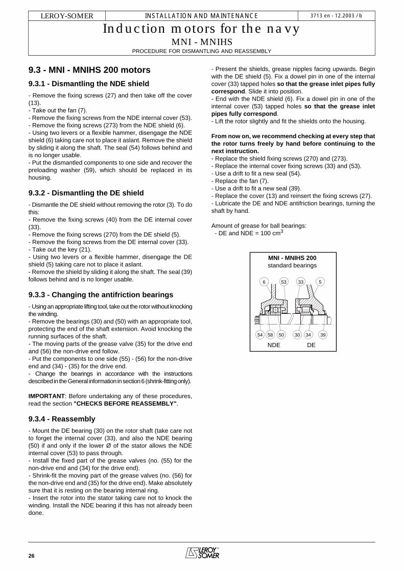
9.3 - MNI - MNIHS 200 motors
9.3.1 - Dismantling the NDE shield
- Remove the fixing screws (27) and then take off the cover(13).- Take out the fan (7).- Remove the fixing screws from the NDE internal cover (53).- Remove the fixing screws (273) from the NDE shield (6).- Using two levers or a flexible hammer, disengage the NDEshield (6) taking care not to place it aslant. Remove the shieldby sliding it along the shaft. The seal (54) follows behind andis no longer usable.- Put the dismantled components to one side and recover thepreloading washer (59), which should be replaced in itshousing.
9.3.2 - Dismantling the DE shield
- Dismantle the DE shield without removing the rotor (3). To dothis:- Remove the fixing screws (40) from the DE internal cover(33). - Remove the fixing screws (270) from the DE shield (5).- Remove the fixing screws from the DE internal cover (33).- Take out the key (21).- Using two levers or a flexible hammer, disengage the DEshield (5) taking care not to place it aslant. - Remove the shield by sliding it along the shaft. The seal (39)follows behind and is no longer usable.
9.3.3 - Changing the antifriction bearings
- Using an appropriate lifting tool, take out the rotor without knockingthe winding.- Remove the bearings (30) and (50) with an appropriate tool,protecting the end of the shaft extension. Avoid knocking therunning surfaces of the shaft.- The moving parts of the grease valve (35) for the drive endand (56) the non-drive end follow.- Put the components to one side (55) - (56) for the non-driveend and (34) - (35) for the drive end.- Change the bearings in accordance with the instructionsdescribed in the General information in section 6 (shrink-fitting only).
IMPORTANT: Before undertaking any of these procedures,read the section "CHECKS BEFORE REASSEMBLY".
9.3.4 - Reassembly
- Mount the DE bearing (30) on the rotor shaft (take care notto forget the internal cover (33), and also the NDE bearing(50) if and only if the lower Ø of the stator allows the NDEinternal cover (53) to pass through.- Install the fixed part of the grease valves (no. (55) for thenon-drive end and (34) for the drive end).- Shrink-fit the moving part of the grease valves (no. (56) forthe non-drive end and (35) for the drive end). Make absolutelysure that it is resting on the bearing internal ring.- Insert the rotor into the stator taking care not to knock thewinding. Install the NDE bearing if this has not already beendone.
- Present the shields, grease nipples facing upwards. Beginwith the DE shield (5). Fix a dowel pin in one of the internalcover (33) tapped holes so that the grease inlet pipes fullycorrespond. Slide it into position.- End with the NDE shield (6). Fix a dowel pin in one of theinternal cover (53) tapped holes so that the grease inletpipes fully correspond.- Lift the rotor slightly and fit the shields onto the housing.
From now on, we recommend checking at every step thatthe rotor turns freely by hand before continuing to thenext instruction.- Replace the shield fixing screws (270) and (273).- Replace the internal cover fixing screws (33) and (53).- Use a drift to fit a new seal (54).- Replace the fan (7).- Use a drift to fit a new seal (39).- Replace the cover (13) and reinsert the fixing screws (27).- Lubricate the DE and NDE antifriction bearings, turning theshaft by hand.
Amount of grease for ball bearings: - DE and NDE = 100 cm3
39343054 58 50
533536
NDE DE
MNI - MNIHS 200standard bearings

27
INSTALLATION AND MAINTENANCE
Induction motors for the navyMNI - MNIHS
PROCEDURE FOR DISMANTLING AND REASSEMBLY
LEROY-SOMER 3713 en - 12.2003 / b
Cable gland - Terminal block (see page 13-14)
MNI - MNIHS 200No. Description No. Description No. Description
1 Wound stator 33 DE internal cover 59 NDE preloading (wavy) washer
2 Housing 34 Fixed part of DE grease valve 64 NDE grease nipple
3 Rotor 35 Moving part of DE grease valve 70 Stator terminal box
5 DE shield 39 DE seal 74 Stator terminal box lid
6 NDE shield 40 Cover fixing screw 270 DE shield fixing screw
7 Fan 42 DE grease nipple 271 DE shield fixing nut
13 Fan cover 50 Non drive end bearing 273 NDE shield fixing screw
21 Shaft extension key 53 NDE internal cover 406 DE Grease valve cover plate
26 Nameplate 54 NDE seal 456 NDE Grease valve cover plate
27 Fan cover screw 55 Fixed part of NDE grease valve
30 Drive end bearing 56 Moving part of NDE grease valve
MNI - MNIHS 200

28
INSTALLATION AND MAINTENANCE
Induction motors for the navyMNI - MNIHS
PROCEDURE FOR DISMANTLING AND REASSEMBLY
LEROY-SOMER 3713 en - 12.2003 / b
9.4 - MNI - MNIHS 225 M to 280 motors
9.4.1 - Dismantling the NDE shield
- Remove the fixing screws (27) and then take off the cover(13).- Remove the shaft extension screw if necessary.- Take out the fan (7).- Remove the fixing screws from the NDE internal cover (53).- Remove the fixing screws (273) from the NDE shield (6).- Remove the fan key if appropriate.- Using two levers or a flexible hammer, disengage the NDEshield (6) taking care not to place it aslant. Remove the shieldby sliding it along the shaft.- Put the dismantled components to one side and recover thepreloading washer (59), which should be replaced in itshousing.
9.4.2 - Dismantling the DE shield
- Dismantle the DE shield without removing the rotor (3). To dothis:- Remove the fixing screws (270) from the DE shield (5).- Remove the fixing screws (40) from the DE internal cover(33).- Take out the key (21).- Using two levers or a flexible hammer, disengage the DEshield (5) taking care not to place it aslant. - Remove the shield by sliding it along the shaft.
9.4.3 - Changing the antifriction bearings
- Using an appropriate lifting tool, take out the rotor withoutknocking the winding.- Take off the DE circlip (38).- Remove the bearings (30) and (50) with an appropriate tool,protecting the end of the shaft extension. Avoid knocking therunning surfaces of the shaft. - Change the bearings in accordance with the instructionsdescribed in the General information in section 6 (shrink-fitting only).
IMPORTANT: Before undertaking any of these procedures,read the section "CHECKS BEFORE REASSEMBLY".
9.4.4 - Reassembly
- Mount the DE bearing (30) on the rotor shaft (take care notto forget the internal cover (33) and the circlip (38), and alsothe NDE bearing (50) if and only if the lower Ø of the statorallows the NDE internal cover (53) to pass through.- Insert the rotor into the stator taking care not to knock thewinding. Install the NDE bearing if this has not already beendone.- Fill the decompression grooves (416) located in theshaftway with grease.- Present the shields, grease nipples facing upwards. Beginwith the DE shield (5). Fix a dowel pin in one of the internalcover (33) tapped holes so that the grease inlet pipes fullycorrespond.- End with the NDE shield (6). Fix a dowel pin in one of theinternal cover (53) tapped holes so that the grease inletpipes fully correspond.- Lift the rotor slightly and fit the shields in place.From now on, we recommend checking at every step that
the rotor turns freely by hand before continuing to thenext instruction.- Replace the shield fixing screws (270) and (273).- Insert the internal cover fixing screws (33) and (53). Replacethe AZ washers to ensure a perfect seal.- Replace the fan key if appropriate.- Replace the fan (7).- Replace the shaft extension screw if necessary.- Replace the cover (13) and reinsert the fixing screws (27).- Lubricate the DE and NDE antifriction bearings, turning theshaft by hand.
Amount of grease for ball bearings: - Frame size 225 - 250: DE and NDE = 120 cm3
- Frame size 280: DE = 170 cm3/NDE = 120 cm3
505333
5 6416
NDE DE
MNI - MNIHS 225 M to 280standard bearings

29
INSTALLATION AND MAINTENANCE
Induction motors for the navyMNI - MNIHS
PROCEDURE FOR DISMANTLING AND REASSEMBLY
LEROY-SOMER 3713 en - 12.2003 / b
Cable gland - Terminal block (see page 13-14)
MNI - MNIHS 225 M to 280No. Description No. Description No. Description
1 Wound stator 26 Nameplate 69 Terminal box base seal
2 Housing 27 Fan cover screw 70 Stator terminal box
3 Rotor 30 Drive end bearing 74 Stator terminal box lid
5 DE shield 33 DE internal cover 81 Cable gland support plate
6 NDE shield 38 DE bearing circlip 89 Connection - Terminal box nozzle
7 Fan 40 Cover fixing screw 270 DE shield fixing screw
10 Turbine or fan screw (280 - 4p) 42 DE grease nipple 271 DE shield fixing nut
11 Brake washer (not shown) (280 - 4p) 50 Non drive end bearing 273 NDE shield fixing screw
12 Lock washer (280 - 4p) 53 NDE internal cover 406 Grease valve cover platedrive end - (plug)
13 Fan cover 59 NDE preloading (wavy) washer 456 Grease valve cover platenon-drive end - (plug)
21 Shaft extension key 64 NDE grease nipple
MNI - MNIHS 225 M to 280

30
INSTALLATION AND MAINTENANCE
Induction motors for the navyMNI - MNIHS
PROCEDURE FOR DISMANTLING AND REASSEMBLY
LEROY-SOMER 3713 en - 12.2003 / b
9.5 - MNI - MNIHS 315 to 355 LD motorsNote:- There is a stirrer at the drive end of the 315 M up to the 355. - Types 315 M and L, and all 355s have fixed NDE bearings:The preloading washer (59) is therefore at the drive end.- Type 315 S has a fixed DE bearing, and the preloadingwasher (59) is therefore at the non-drive end.This should be taken into account during dismantling/reassembly operations.
9.5.1 - Dismantling the NDE shield
- Remove the grease nipple extension (65).- Remove the fixing screws (27) and then take off the cover(13).- Remove the screws and washer from the shaft extension.- Take out the fan (7). - Take out the fan key (not shown) and the moving part of thegrease valve (56).- Remove the fixing screws from the NDE internal cover (53).- Remove the fixing screws (273) from the NDE shield (6).- Using two levers or a flexible hammer, disengage the NDEshield (6). Remove the shield by sliding it along the shaft.- Put the dismantled components to one side and recover thepreloading washers (59), which should be replaced in theirhousing (for the 315 S).
9.5.2 - Dismantling the DE shield
- Dismantle the DE shield without removing the rotor (3). To dothis:- Take out the key (21).- Heat the moving part of the DE grease valve (35). Unscrewand remove it.- Remove the fixing screws from the DE internal cover (33).- Remove the fixing screws (270) from the DE shield.- Using two levers or a flexible hammer, disengage the DE shield(5) taking care not to place it aslant. - Remove the shield by sliding it along the shaft. - Place the dismantled components to one side and recoverpart no. (35) which should be replaced in its housing, alongwith the preloading washers (59) (for the 315 M to 355 LD).
9.5.3 - Changing the antifriction bearings
- Using an appropriate lifting tool, take out the rotor without knockingthe winding.- Remove the bearings (30) and (50) with an appropriate tool,protecting the end of the shaft extension. Avoid knocking therunning surfaces of the shaft. - Change the bearings in accordance with the instructionsdescribed in the General information in section 6 (shrink-fitting only).
IMPORTANT: Before undertaking any of these procedures,read the section "CHECKS BEFORE REASSEMBLY".
9.5.4 - Reassembly
- Mount the DE bearing (30) on the rotor shaft (take care notto forget the internal cover (33), and also the NDE bearing(50) and the NDE internal cover (53)).
- Insert the rotor in the stator taking care not to knock thewinding.- Don‘t forget to replace the preloading washers (59) in theirhousing.- Begin with the fixed bearing (see above). Fix a dowel pin inone of the internal cover tapped holes so that the greaseinlet pipes fully correspond.- End with the non-fixed bearing. Fix a dowel pin in one of theinternal cover tapped holes so that the grease inlet pipesfully correspond.- Lift the rotor slightly and fit the shields in place.
From now on, we recommend checking at every step thatthe rotor turns freely by hand before continuing to thenext instruction.- Replace the shield fixing screws (270) and (273).- Replace the internal cover fixing screws (33) and (53).- Refit the moving part of the grease valve (56).- Replace the fan (7) with its key.- Replace the shaft extension screw with its washer.- Replace the cover (13).- Coat the thread of the moving part of the DE grease valve(35), with anti-vibration adhesive. Screw it tight.- Lubricate the DE and NDE bearings.
Amount of grease for ball bearings: - Frame size 315S: DE and NDE = 235 cm3/frame size 315 M/L: DE and NDE = 335 cm3/frame size 355: DE and NDE = 445 cm3
59 6 53 33 5
50 3056 35
NDE DE
MNI - MNIHS 315 STstandard bearings
6 53 33 5 44
50 3056 35
NDE DE
MNI - MNIHS 315 M, L355 LA, LB, LC, LDstandard bearings

31
INSTALLATION AND MAINTENANCE
Induction motors for the navyMNI - MNIHS
PROCEDURE FOR DISMANTLING AND REASSEMBLY
LEROY-SOMER 3713 en - 12.2003 / b
Cable gland - Terminal block (see page 13-14)
MNI - MNIHS 315 to 355 LDNo. Description No. Description No. Description
1 Wound stator 27 Fan cover screw 65 Extension for NDE grease nipple
2 Housing 30 Drive end bearing 70 Stator terminal box
3 Rotor 33 DE internal cover 74 Stator terminal box lid
5 DE shield 35 Moving part of DE grease valve 81 Cable gland support plate
6 NDE shield 40 Cover fixing screw 89 Connection - Terminal box nozzle
7 Fan 42 DE grease nipple 122 Stirrer (only from 315 M to 355 LD)
10 Turbine or fan screw 43 Extension for DE grease nipple 270 DE shield fixing screw
11 Brake washer (not shown) 50 Non drive end bearing 271 DE shield fixing nut
12 Lock washer 53 NDE internal cover 273 NDE shield fixing screw
13 Fan cover 56 Moving part of NDE grease valve 406 DE Grease valve cover plate
21 Shaft extension key 59 NDE preloading (wavy) washer 456 NDE Grease valve cover plate
26 Nameplate 64 NDE grease nipple
MNI - MNIHS 315 to 355 LD

LEROY-SOMER 16015 ANGOULÊME CEDEX - FRANCE
RCS ANGOULÊME N° B 671 820 223S.A. au capital de 62 779 000 €
www.leroy-somer.com


