Pure & Appl. Chern., Vol. 60, No. 5, pp. 685-696, 1988. Printed in Great Britain. @ 1988 IUPAC Inductively coupled plasmas in analytical atomic spectrometry: excitation mechanisms and analytical feasibilities Hiroki Haraguchi, Tetsuya Hasegawg Department of Chemistry, Faculty of Science, The University of Tokyo, 7-3-1, Hongo, Bunkyo-ku, Tokyo 113, Japan and Mohamad Abdullaht Abstract - The excitation mechanisms in an inductively coupled plasma are discussed based on a collisional-radiative process theory. In the theory, the kinetic processes such as electron impact excitation and de-excitation, electron impact ionization and three-body recombination, spontaneous emission and induced absorption, radiative recombination, Penning ioniza- tion, and charge transfer are taken into consideration to interpret the excitation mechanisms in the argon ICP. These considerations suggest that the electron-collisional excitatiodde-excitation and ionization processes are dominant in determining the atom and ion populations in the normal analytical zone, although the non-LTE properties of the plasma are caused mainly by the radiative processes. In addition, the graphite cup direct insertion technique will be discussed as a new analytical method for solution and solid sample analysis. INTRODUCTION An inductively coupled plasma (ICP) using argon gas has been developed as an excitation source for atomic emission spectrometry since the pioneer works of V. A. Fassel and S. Green- field (refs. 1,2). The argon ICP is generated by applying RF power (usually 27.12 MHz in frequency and 0.5-2.5 kW in forward power) to argon gas, which flows through a three cylindrical quartz tube (so-called "plasma torch" ) as the three-separated gas flows such as coolant, intermediate, and carrier gases. In general, the temperature as well as the electron number density in the central zone of the ICP are lower than those in the surroundings. This plasma structure is called "annular shape" or "doughnut" structure. The annular shape of the ICP makes it much easier and efficient to introduce the solution samples into the central part of the plasma. Thus the argon ICP can be an efficient excitation source for many elements in various samples. As is well known, inductively coupled plasma atomic emission spectrometry (ICP-AES) provides the excellent analytical feasibilities such as high sensitivity, good accuracy and precision, wide dynamic ranges of working curves, multielement detection capability and so forth (refs. 3-5). Consequently, ICP-AES has been extensively used in various scientific fields as an useful analytical method. It has also been known that a characteristic property of the argon ICP is non-LTE (local thermodynamic equilibrium) which has been appreciated by the overpopulation of ions compared to the populations of atoms when calculated under the LTE (Boltzmann distribution) condition. In order to understand such non-LTE phenomena of the ICP, many physical and spectroscopic parameters of the plasma especially such as various plasma temperatures and electron number densities have been measured for plasma diagnostics (refs. 6-12). As the results, the Pen- ning ionization (refs. 13,14), charge transfer (ref. 15), radiation trapping (refs. 16,17) and so forth have been proposed as the possible excitation mechanisms. However, these non- linear reactions can not explain the whole figures of excitation processes in the ICP (refs. 18-21). Recently we have proposed a collisional-radiative process theory which is very useful to ap- preciate the fundamental properties and excitation mechanisms in the argon ICP (refs. 22-26). In this paper, the excitation mechanisms of argon, magnesium and cadmium are discussed from the population density distributions and kinetic parameters which are estimated from the cal- culations by the collisional-radiative process theory. For the practical purpose in analytical chemistry, the argon ICP has been used for element analysis of various samples in the wide concentration ranges. However, the analysis of small volume solution or solid sample at the 1.11- or 1.19-order, respectively, are still difficult by *Present address: Department of Chemical Industry, Faculty of Engineering, The University t Present address: Department of Chemistry, University of Alberta, Edmonton, Alberta, Canada of Tokyo, 7-3-1, Hongo, Bunkyo-ku, Tokyo 113, Japan. TG6 2G2. 685
Transcript
Pure & Appl. Chern., Vol. 60, No. 5, pp. 685-696, 1988. Printed in Great Britain. @ 1988 IUPAC
Inductively coupled plasmas in analytical atomic spectrometry: excitation mechanisms and analytical feasibilities
Hiroki Haraguchi, Tetsuya Hasegawg
Department of Chemistry, Faculty of Science, The University of Tokyo, 7-3-1, Hongo, Bunkyo-ku, Tokyo 113, Japan
and Mohamad Abdullaht
Abstract - The excitation mechanisms in an inductively coupled plasma are discussed based on a collisional-radiative process theory. In the theory, the kinetic processes such as electron impact excitation and de-excitation, electron impact ionization and three-body recombination, spontaneous emission and induced absorption, radiative recombination, Penning ioniza- tion, and charge transfer are taken into consideration to interpret the excitation mechanisms in the argon ICP. These considerations suggest that the electron-collisional excitatiodde-excitation and ionization processes are dominant in determining the atom and ion populations in the normal analytical zone, although the non-LTE properties of the plasma are caused mainly by the radiative processes. In addition, the graphite cup direct insertion technique will be discussed as a new analytical method for solution and solid sample analysis.
INTRODUCTION
An inductively coupled plasma (ICP) using argon gas has been developed as an excitation source for atomic emission spectrometry since the pioneer works of V. A. Fassel and S. Green- field (refs. 1,2). The argon ICP is generated by applying RF power (usually 27.12 MHz in frequency and 0.5-2.5 kW in forward power) to argon gas, which flows through a three cylindrical quartz tube (so-called "plasma torch" ) as the three-separated gas flows such as coolant, intermediate, and carrier gases. In general, the temperature as well as the electron number density in the central zone of the ICP are lower than those in the surroundings. This plasma structure is called "annular shape" or "doughnut" structure. The annular shape of the ICP makes it much easier and efficient to introduce the solution samples into the central part of the plasma. Thus the argon ICP can be an efficient excitation source for many elements in various samples. As is well known, inductively coupled plasma atomic emission spectrometry (ICP-AES) provides the excellent analytical feasibilities such as high sensitivity, good accuracy and precision, wide dynamic ranges of working curves, multielement detection capability and so forth (refs. 3-5). Consequently, ICP-AES has been extensively used in various scientific fields as an useful analytical method.
It has also been known that a characteristic property of the argon ICP is non-LTE (local thermodynamic equilibrium) which has been appreciated by the overpopulation of ions compared to the populations of atoms when calculated under the LTE (Boltzmann distribution) condition. In order to understand such non-LTE phenomena of the ICP, many physical and spectroscopic parameters of the plasma especially such as various plasma temperatures and electron number densities have been measured for plasma diagnostics (refs. 6-12). As the results, the Pen- ning ionization (refs. 13,14), charge transfer (ref. 15), radiation trapping (refs. 16,17) and so forth have been proposed as the possible excitation mechanisms. However, these non- linear reactions can not explain the whole figures of excitation processes in the ICP (refs. 18-21).
Recently we have proposed a collisional-radiative process theory which is very useful to ap- preciate the fundamental properties and excitation mechanisms in the argon ICP (refs. 22-26). In this paper, the excitation mechanisms of argon, magnesium and cadmium are discussed from the population density distributions and kinetic parameters which are estimated from the cal- culations by the collisional-radiative process theory.
For the practical purpose in analytical chemistry, the argon ICP has been used for element analysis of various samples in the wide concentration ranges. However, the analysis of small volume solution or solid sample at the 1.11- or 1.19-order, respectively, are still difficult by
*Present address: Department of Chemical Industry, Faculty of Engineering, The University
t Present address: Department of Chemistry, University of Alberta, Edmonton, Alberta, Canada of Tokyo, 7-3-1, Hongo, Bunkyo-ku, Tokyo 113, Japan.
TG6 2G2.
685
686 H. HARAGUCHI, T. HASEGAWA AND M. ABDULLAH
the present analytical techniques. Thus, the graphite cup direct insertion device has been developed to extend the analytical feasibilities of the ICP even for direct solid sample analyisis. Such works will be also discussed in the present paper.
COLLISIONAL-RADIATIVE PROCESS THEORY
In order to interpret the rate processes in the hydrogen and hydrogen-like plasmas, a collisional-radiative model has been proposed by Fujimoto (refs. 27-30). The present authors have tried to apply the collisional-radiative model to the theoretical calculation of the electronic state populations and the kinetic processes of argon and other analyte metals in the argon ICP (refs. 22-26). In the collisional-radiative process theory, the following kinetic processes are taken into consideration.
(i) electron impact excitation and de-excitation:
(ii) electron impact ionization and three-body recombination:
(iii) induced absorption and spontaneous emission:
(iv) radiative recombination:
In addition, the following non-linear reactions are also considered as possible ionization processes in the case of analyte metals.
(v) Penning ionization (Ar*; excited argon atom):
P m
m ' P
x ( ~ ) + Ar* -. X+ + Ar + e-
(vi) charge transfer (Ar'; argon ion): C
x(p) + Ar' P X+ + Ar
c ' P
( 5 )
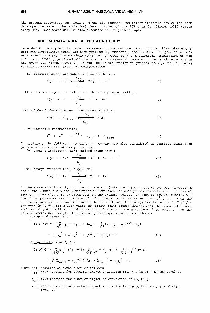
In the above equations, k, c1, m, and c are the (relative) rate constants for each process, A and B the Einstein's A and B constants for emission and absorption, respectively. In case of argon, for example, X(p) is argon atom in the p-energy state. In case of analyte metals, all the above processes are considered for both metal atom (X(p)) and ion (X+(p')). Then the rate equations for atom and ion number densities in all the energy levels, e.g., dn(X(p))/dt and dn(X+(p' ) )/dt, are solved under the steady-state approximation, where transport phenomena such as ambipolar diffusion and convection of electron are also taken into account. In the case of argon, for example, the following rate equations are considered.
For wound state (p=l):
+ kilne3 + aine2 - (DaD2ne - vVne) = 0 (7)
For excited states (p>l):
where the notations of symbols are as follows: kpq: rate constant for electron impact excitation from the level p to the level q,
kqp: rate constant for electron impact de-excitation from q to p,
kpi: rate constant for electron impact ionization from p to the ionic ground-state level i,
inductively coupled plasmas in analytical atomic spectrometry 687
kip: rate constant for three-body recombination from i to p,
A app: transition probability for transition from p to q,
c1 * rate constant for radiative recombination to level p,
Da : ambipolar diffusion constant,
v : drift velocity of electron,
w P '
ne : electron number density.
In the argon ICP, the number density of argon ion n(Ar+) is almost equal to that of electron ne, and so the terms of nen(Ar+) and and three- body recombination, respectively, are replaced by ne2 and ne3 in the case of argon. In the case of analyte metals, however, such terms should be taken as those including the number densities of atom and ion, and also the terms for the Penning ionization and charge transfer are added to Eqs. (7) and (8). In Fig. 1, the energy-level diagram for argon atom is shown, which are taken into account in the present calculation. Further, the atom and ion energy- levels of magnesium considered are summarized in Table 1, along with their properties.
ne2n(Ar+) for electron impact de-excitation
*PI/? 16 2P3,2
p i r +
- 4 P'
4st3/21; ( A r m )
Fig. 1. Simplified energy diagram for argon.
ground state 0
Table 1. Coalesced bound level properties of magnesium atom and ion.
term symbol statistical mean energy term symbol statistical mean energy weight (ev) weight (ev)
It should be noted that all the rate constants as well as the electron number density ne, which are included in Eqs. (7) and (8), are the functions of electron temperature Te. Therefore, it is most important to know electron temperature of the argon ICP. In the present study, electron temperature was obtained from the continuum radiation without assump- tion of thermal equilibrium (ref. 24). When the radiation recombination process is dominant compared to the bremsstrahlung or retardation in the ionic field, the total emission coeffi- cient E,,,~(X, Te) at the wavelength A is given by Eq. (9).
688 H. HARAGUCHI, T. HASEGAWA AND M. ABDULLAH
l- t 0
10141 , , , , ,
0 1 2 3 4 5 0 1 2 3 4 5 0
radial position ( mm) radial position (mm )
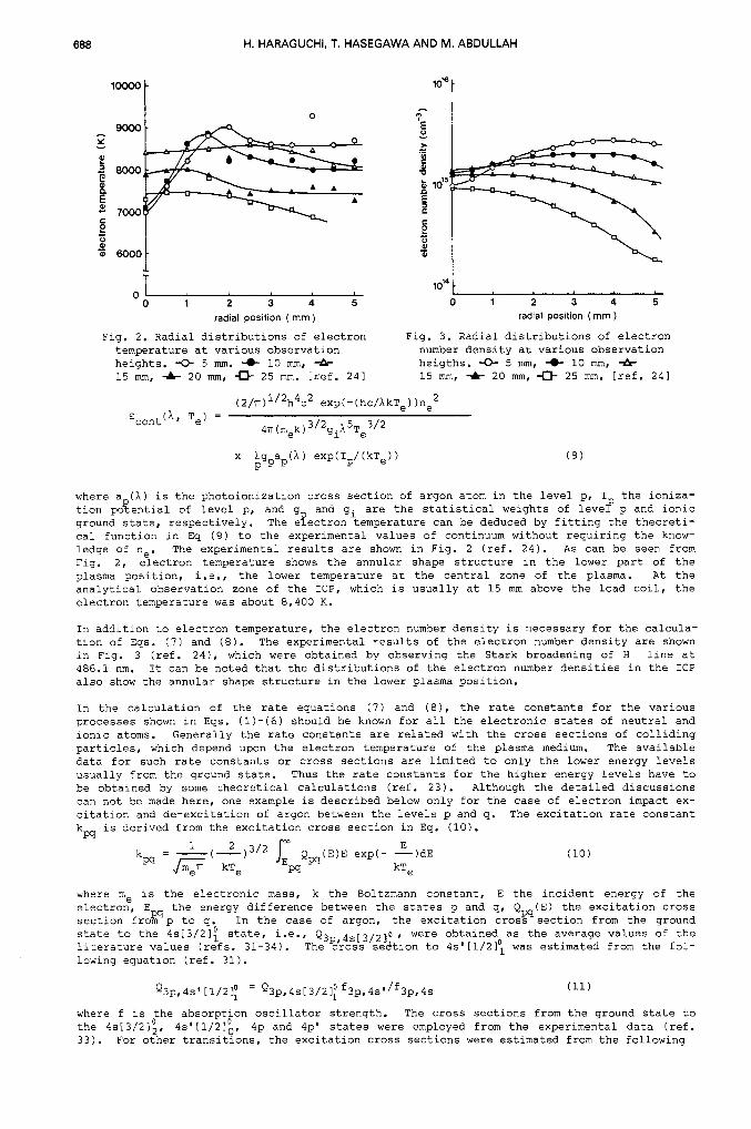
Fig. 2. Radial distributions of electron Fig. 3 . Radial distributions of electron temperature at various observation number density at various observation heights. -0- 5 mm. -0- 10 mm, 4- heigths. -0- 5 mm, 4 10 mm, 4- 15 mm, -A- 20 mm, 0 25 mm. [ref. 241 15 mm, 4- 20 mm, c)- 25 mm. [ref. 241
where a (A) is the photoionization cross section of argon atom in the level p, I the ioniza- tion poqential of level p, and g and gi are the statistical weights of levef p and ionic ground state, respectively. The eyectron temperature can be deduced by fitting the theoreti- cal function in Eq (9) to the experimental values of continuum without requiring the know- ledge of ne. The experimental results are shown in Fig. 2 (ref. 24). A s can be seen from Fig. 2, electron temperature shows the annular shape structure in the lower part of the plasma position, i.e., the lower temperature at the central zone of the plasma. At the analytical observation zone of the ICP, which is usually at 15 mm above the load coil, the electron temperature was about 8,400 K.
In addition to electron temperature, the electron number density is necessary for the calcula- tion of Eqs. ( 7 ) and (8). The experimental results of the electron number density are shown in Fig. 3 (ref. 24), which were obtained by observing the Stark broadening of H line at 486.1 nm. It can be noted that the distributions of the electron number densities in the ICP also show the annular shape structure in the lower plasma position.
In the calculation of the rate equations ( 7 ) and (8), the rate constants for the various processes shown in Eqs. (1)-(6) should be known for all the electronic states of neutral and ionic atoms. Generally the rate constants are related with the cross sections of colliding particles, which d.epend upon the electron temperature of the plasma medium. The available data for such rate constants or cross sections are limited to only the lower energy levels usually from the ground state. Thus the rate constants for the higher energy levels have to be obtained by some theoretical calculations (ref. 23). Although the detailed discussions can not be made here, one example is described below only for the case of electron impact ex- citation and de-excitation of argon between the levels p and q. The excitation rate constant k, is derived from the excitation cross section in Eq. (10).
(10)
where me is the electronic mass, k the Boltzmann constant, E the incident energy of the electron, Em the energy difference between the states p and q, Qm(E) the excitation cross section from p to q. In the case of argon, the excitation cross section from the ground state to the 4s[3/21: state, i.e., Q3p 4s,3/210 ,, were obtained as the average values of the literature values (refs. 31-34). The &oss sedtion to 4s'[1/21: was estimated from the fol- lowing equation (ref. 31).
Q3p,4s' w 2 1 ; = Q3pr4s[3/21; f3p,4s'/f3p,4s (11)
where f is the absorption oscillator strength. The cross sections from the ground state to the 4s[3/21;, 4p and 4p' states were employed from the experimental data (ref. 33). For other transitions, the excitation cross sections were estimated from the following
4s'[1/210,,
hductively coupled plasmas in analytical atomic spectrometry 689
semi-empical formula (ref. 35). For an optically allowed transition:
where R is Rydberg energy, a. Bohr radius, Uw the normalized impact energy, i.e., U = w and 6, y, 6 are the adjustable constants. an optically forbidden transition:
where B is the interpolated value from the hydrogenic cross section (refs. 36,37), n * and n * are%e effective quantum numbers for levels p and q.
The excitation rate constants were determined by numerical integration (70 points) over a Maxwell-Boltzmann energy distribution of electron in the electron energy region larger than
according to Eq. (11). Then the de-excitation rate constant was obtained by detailed k!ancing of the following equation.
P q
k = k g /g exp(Ew/kTe) 9P W P 9 (14)
The further details for the calculation of the rate constants or cross sections in other kinetic processes should be referred to the literatures (refs. 22-25).
POPULATION DENSITIES AND KINETIC PROCESSES OF ARGON
By solving the rate equations ( 7 ) and ( 8 ) , the electronic state population densities of atom and ion can be estimated, as well as the electron flows which indicate the contribution of each kinetic process shown in Eqs. ( 1 ) - ( 6 ) . As an example, the population density distribu- tions of argon atoms in the ICP are summarized in Table 2 (ref. 22), where the distributions were calculated under the conditions of electron temperature 9,000 K and electron number den- sity 5 x cm-3 (refs. 38,39). Although the plasma parameters used in calculation for Table 2 were obtained for the 40 MHz ICP and the cal- culation was made in the preliminary stage of our theoretical consideration, the results in Table 2 show some interesting features of the argon ICP. It should be noted first that argon atoms are populated to great extent in all the electronic states. As is seen from Table 2, the total number density of metastable argon was ca. 0.6 x 10" cmm3, which is similar to the experi- mental data obtained by the line- and continuum- source atomic absorption methods (refs. 12,40). This fact suggests that the calculated values for the whole electronic states in Table 2 may be reliable, and thus the radiative-collisional process theory can be applied to further consi- deration on plasma diagnostics in the argon ICP. It should be stressed here based on the results in Table 2 that metastable argon atoms at the states of 4s[3/21; nd 4s'[1/2l0 are not special, as considered in the hypothetical excitation mechanisms of the Penning ionization (refs. 13, 14) and radiation trapping (refs. 16,17). Fur- ther it is interesting that population density of metastable argon atoms is almost equal to that of radiative 4s argon atom at the 4s[3/21; and 4s'[1/21; states. The equal populations are caused by internal conversion due to electron collisions. Since energy differences between radiative and metastable 4s levels are small (0.23 and 0.25 eV), internal conversion between those two levels due to electron collision can easily occur because the electron population of with the smaller kinetic energy is much larger than that with the larger energy according to the Maxwell-Boltzmann distribution of electron
Table 2. Population densities of argon calculated based on a collisional and radiative model state approximation . tref.221 aYder a steady
a) The values of Te = 9,000 K and ne = 5x10I4 cm-3 were used.
690 H. HARAGUCHI, T. HASEGAWA AND M. ABDULLAH
‘i ‘i
10“
100 - D
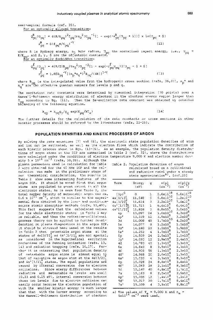
0 - Fig. 4. Population density distribu- n 31
lo9 2
\ 10
tion for argon energy states. Solid line denotes the LTE value and the data points are the results obtained from the present calcula- lation. Observation height is 15 mm and radial position is 0 mm. [ref. 241
1 1 0 ~ 11 13 14
10” I, 15
extitalion energy 1 eV 1
energy at Te = 9,000 K. Then the results in Table 2 indicate that all the energetic electrons besides metastable argon atoms should be also taken into account when the Penning ionization process is appreciated as the possible excitation mechanism in the ICP.
The electronic state population density distribution of argon atom in the argon ICP is shown in Fig. 4 (ref. 24). The population densities plotted in Fig. 4 were obtained by the cal- culation of the rate equations under the plasma conditions of Te = 8,400 K and ne = 1.4 x
The LTE values is shown as the solid line in Fig. 4. It is noted here that the lower energy levels of argon atom, espe- cially the ground state and 4s levels, are slightly overpopulated compared to the LTE values, while those at the higher energy levels are close to the LTE. Such deviations from the LTE can be qualitatively understood by the following consideration. If the population densities of argon atom in the electronic states are determined only by the electron-collisional processes shown by Eqs. (1) and (2), argon atoms may be in the LTE. However, as has been discussed in the radiative-collisional process theory, the radiative processes such as spon- taneous emission and radiative recombination, which are shown in Eqs. (3) and (4), are in- volved in the excitation and de-excitation of argon atom. Thus it appears that such radia- tive processes cause the deviations of argon atom from the LTE. These facts can be ap- parently appreciated from the consideration of the electron flows between the electronic states.
~ m - ~ , which were different from those used in Table 2.
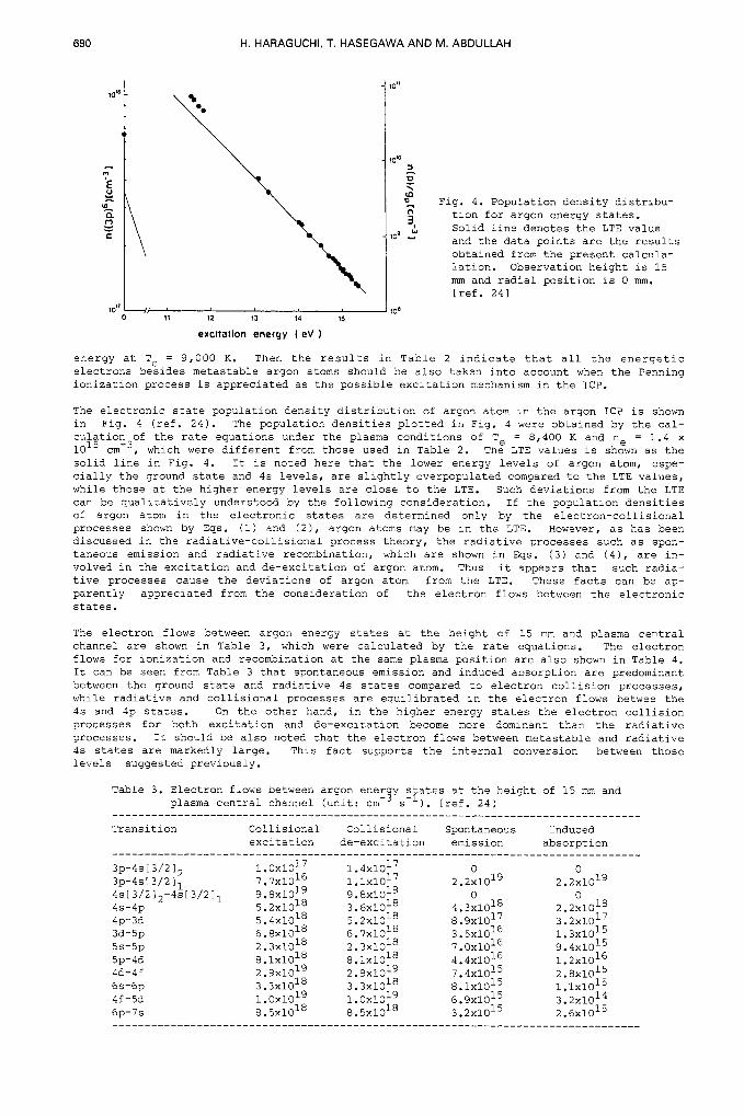
The electron flows between argon energy states at the height of 15 mm and plasma central channel are shown in Table 3, which were calculated by the rate equations. The electron flows for ionization and recombination at the same plasma position are also shown in Table 4. It can be seen from Table 3 that spontaneous emission and induced absorption are predominant between the ground state and radiative 4s states compared to electron collision processes, while radiative and collisional processes are equilibrated in the electron flows betwee the 4s and 4p states. On the other hand, in the higher energy states the electron collision processes for both excitation and de-excitation become more dominant than the radiative processes. It should be also noted that the electron flows between metastable and radiative 4s states are markedly large. This fact supports the internal conversion between those levels suggested previously.
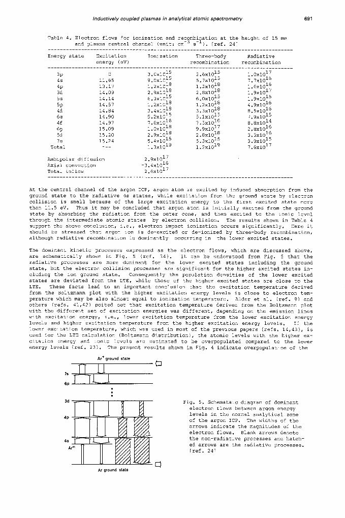
Table 3. Electron flows between argon ener y states at the height of 15 mm and plasma central channel (unit: cm-’ s-I). [ref. 241
Ambipolar diffusion 2.9~10’~ Axial convection -3.4~10’~ Total inflow 2.6~10’~ ________________________________________-----------------------------------------
At the central channel of the argon ICP, argon atom is excited by induced absorption from the ground state to the radiative 4s states, while excitation from the ground state by electron collision is small because of the large excitation energy to the first excited state more than 11.5 eV. Thus it may be concluded that argon atom is initially excited from the ground state by absorbing the radiation from the outer cone, and then excited to the ionic level through the intermediate atomic states by electron collision. The results shown in Table 4 support the above conclusion, i.e., electron impact ionization occurs significantly. Here it should be stressed that argon ion is de-excited or de-ionized by three-body recombination, although radiative recombination is dominantly occurring in the lower excited states.
The dominant kinetic processes expressed as the electron flows, which are discussed above, are schematically shown in Fig. 5 (ref. 24). It can be understood from Fig. 5 that the radiative processes are more dominant for the lower excited states including the ground state, but the electron collision processes are significant for the higher excited states in- cluding the ion ground state. consequently the population densities of the lower excited states are deviated from the LTE, while those of the higher excited states are close to the LTE. These facts lead to an important conclusion that the excitation temperature derived from the Boltzmann plot with the higher excitation energy levels is close to electron tem- perature which may be also almost equal to ionization temperature. Alder et al. (ref. 9) and others (refs. 41,42) poited out that excitation temperature derived from the Boltzmann plot with the different set of excitation energies was different, depending on the emission lines with excitation energy, i.e., lower excitation temperature from the lower excitation energy levels and higher excitation temperature from the higher excitation energy levels. If the lower excitation temperature, which was used in most of the previous papers (refs. 14,43), is used for the LTE calculation (Boltzmann distribution), the atomic levels with the higher ex- citation energy and ionic levels are estimated to be overpopulated compared to the lower energy levels (ref. 23). The present results shown in Fig. 4 indicate overpopulation of the
Ar’ ground state
7 s F ”
6~ . . . Fig. 5. Schemataic diagram of dominant electron flows between argon energy levels in the normal analytical zone of the argon ICP. The widths of the arrows indicate the magnitudes of the electron flows. Blank arrows denote the non-radiative processes and hatch- ed arrows are the radiative processes. [ref. 241
Ar ground Stale
692 H. HARAGUCHI, T. HASEGAWA AND M. ABDULLAH
lower energy levels. Such a discrepancy is caused by different temperature used in the LTE calculation. Therefore, it is highly recommended that electron temperature or excitation temperature derived from the higher energy levels should be used for the LTE consideration. It should be stressed here repeatedly that the deviation of the lower energy levels from the LTE is caused by the radiative decay due to spontaneous emission, and that the higher energy levels with the small energy gaps are close to the LTE because their populations are deter- mined mainly by thermal processes due to electron collision.
Although the results are not shown here, the population density distribution at the central channel of observation height 25 mm showed the lower populations of almost all the levels in- cluding the ground state level compared to the LTE values. This is because the three-body recombination occurs more predominantly than electron-collision ionization. Thus it should be stressed that the argon ICP is the recombining plasma in the higher plasma position.
EXCITATION MECHANISMS A N D ELECTRONIC STATE POPULATIONS OF M A G N E S I U M A N D C A D M I U M
In order to appreciate magnesium excitation mechanism, the radiative-collisional process theory has been applied to the calculations of the electronic state population densities and the relative reaction rates of magnesium in the argon ICP. The population density distribu- tion of magnesium atom and ion at the central channel of observation height 15 mm is shown in Fig. 6 (ref. 25), where the atomic and ionic energy levels listed in Table 1 were taken into consideration, and the rate equations for both atom and ion, i.e., dn(Mg(p))/dt and dn(Mg+(p'))/dt, were solved at Te = 8,400 K and ne = 1.4 x 10¹⁵ ~ m - ~ . The non-linear terms for the Penning ionization and charge transfer were added to those equations.
The ordinate in Fig. 6 shows the population densities divided by the number density of doubly ionized atom. ex- perimental values obtained from the emission intensities of magnesium lines (10 pg/ml mag- nesium solution was nebulized) were normalized by the theoretical values of ionic 3p level. As can be seen in Fig. 6, the calculated population densities agree well with the experimen- tal ones. This fact may indicate that the present collisional-radiative process theory can be helpful for the discussion on the magnesium excitation mechanism in the argon ICP. It is clearly seen in Fig. 6 that all the neutral atom levels and the lowerenergy levels of singly ionized atom levels are overpopulated compared to the LTE values, while the population den- sities of singly ionized atoms in the higher levels are close to the LTE values. It should be noted here that the population density of ionic ground state is approximately 4-times larger than the LTE value. This extent of overpopulation of magnesium ion is much larger than that of argon ground state atom previously discussed. The large overpopulation of mag- nesium ion is interpreted by no or less induced absorption, while the overpopulation of argon atom due to spontaneous emission is compensated by induced absorption.
The relative reaction rates for the collisional and radiative processes calculated are sum- marized in Table 5. It can be seen from Table 5 that spontaneous emission occurs sig- nificantly in the lower levels of magnesium ion, which results in overpopulation of those levels. The collisional excitation and de-excitation processes for the higher levels of mag- nesium ion are almost equilibrated. Thus the population densities of the higher levels are close to the LTE values.
Since the measurement of the number density of Mg2+ was difficult,the
In the case of magnesium neutral atom, the contribution of spontaneous emission is also remarkablly large in the lower energy levels, which such a contribution becomes less signifi-
Fig. 6. Population density distributions for magnesium at the height of 15 mm and radius of 0 mm. -. . LTE value at Te = 8,400 K, ---: LTE value at 7,500 K normalized to the calculated value of Mg+(3p), 0 : calculated value, o : measured value normalized to the calculated value of Mc3+(3p).
energy, eV
Inductively coupled plasmas in analytical atomic spectrometry 693
cant for the higher energy levels. This, of couse, causes the overpopulation of the lower levels of neutral atom in balance. Furthermore, it should be stressed here that all the energy levels of neutral atom are overpopulated. The overall overpopulation of neutral atom can be appreciated by the collisional equilibria between the atomic levels and ionic qround
Table 5. Relative reaction rates for collisional and radiative processes between magnesium energy levels.
a) normalized as 1.0, b) collisional ionization, c) three-body recombination, d) radiative recombination.
h t Cd 10 -
0
state level through three-body re- combination process.
According to the present calculation, the relative reaction rates of ioni- zation and recombination were in total, 3.2 x lo1 and 3.0 x 10‘ for electron collision, 2.3 x and 9.7 x for Penning ionization, 2.1 x lo-’ and 1.2 x lo-’ for charge transfer, respectively. These re- sults indicate that magnesium is ionized dominantly by electron impact process, and ionization due to Penning and charge transfer processes is negligibly small.
The population density distribution of cadmium at the central channel of observation height 15 mm is shown in Fig. 7 (ref. 26). The electronic state population densities were obtained in similar manner to those of magnesium. In the consideration on cadmium, the 15 atomic levels from the ground state 5slS ( 0 eV) to 7plP (8.12 eV) and 14 singly-ionize
Fig. 7. Population density distribution for cadmium. Observation height: 15 mm, radius: 0 mm.
energy I eV
levels from the ionic ground state 5s2S ( 0 eV) to 9s2S (15.34 eV) were taken into account, As can be seen from Fig. 7, the population densities of the atomic levels and the lower ionic levels show significant overpopulation compared to the LTE values in similarity to magnesium. The extent of deviation from LTE, however, is larger in the case of cadmium than that in the case of magnesium. This is clearly due to the fact that cadmium has large ionization poten- tial and energy differences between the lower energy levels compared to magnesium. According to our preliminary results, the contributions of non-linear reactions such as Penning ioniza- tion and charge transfer processes are significantly large in the case of cadmium; the former is ca. 2 % and the latter ca. 10 %.
GRAPHITE CUP DIRECT INSERTION TECHNIQUE FOR SOLUTION AND SOLID SAMPLE ANALYSIS
As described before, ICP-AES was originally developed for the methods of solution analysis (refs. 3-5), where the conventional pneumatic nebulizers of cross flow- and concentric-types were usually used for solution sample introduction into the plasma. However, the extensive applications of ICP-AES to the various samples have required some expoitation of the ver- satile sample introduction devices. The micro-sampling devices, which allow introduction of ul-order of sample, have been proposed for analysis of biological and environmental samples (refs. 44-47). Another requirement for the modern ICP-AES technique is direct introduction of solid samples especially in industry and geochemistry (refs. 48-52). Hence in our
694 H. HARAGUCHI, T. HASEGAWA AND M. ABDULLAH
graphite Ild .) 1 mm hole
135mm We graphite cup 1 .p
220.3 nrn
, i - 20s
228.8 nrn
- a 20s - 20 s
0 Tirne(s)
1 cm
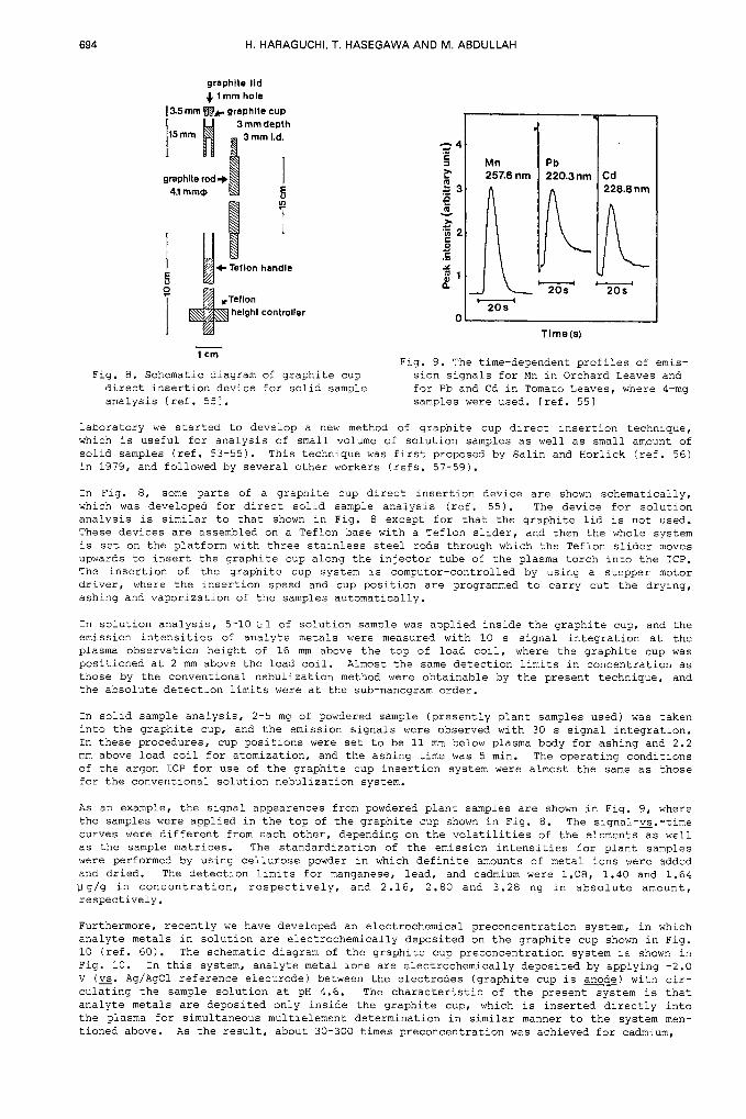
Fig. 8 . Schematic diagram of graphite cup direct insertion device for solid sample analysis [ref. 551.
Fig. 9. The time-dependent profiles of emis- sion signals for Mn in Orchard Leaves and for Pb and Cd in Tomato Leaves, where 4-mg samples were used. [ref. 551
laboratory we started to develop a new method of graphite cup direct insertion technique, which is useful for analysis of small volume of solution samples as well as small amount of solid samples (ref. 53-55). This technique was first proposed by Salin and Horlick (ref. 56) in 1979, and followed by several other workers (refs. 57-59).
In Fig. 8, some parts of a graphite cup direct insertion device are shown schematically, which was developed for direct solid sample analysis (ref. 55). The device for solution analysis is similar to that shown in Fig. 8 except for that the graphite lid is not used. These devices are assembled on a Teflon base with a Teflon slider, and then the whole system is set on the platform with three stainless steel rods through which the Teflon slider moves upwards to insert the graphite cup along the injector tube of the plasma torch into the ICP. The insertion of the graphite cup system is computor-controlled by using a stepper motor driver, where the insertion speed and cup position are programmed to carry out the drying, ashing and vaporization of the samples automatically.
In solution analysis, 5-10 u l of solution sample was applied inside the graphite cup, and the emission intensities of analyte metals were measured with 10 s signal integration at the plasma observation height of 16 nun above the top of load coil, where the graphite cup was positioned at 2 mm above the load coil. Almost the same detection limits in concentration as those by the conventional nebulization method were obtainable by the present technique, and the absolute detection limits were at the sub-nanogram order.
In solid sample analysis, 2-5 mg of powdered sample (presently plant samples used) was taken into the graphite cup, and the emission signals were observed with 30 s signal integration. In these procedures, cup positions were set to be 11 mm below plasma body for ashing and 2.2 mm above load coil for atomization, and the ashing time was 5 min. The operating conditions of the argon ICP for use of the graphite cup insertion system were almost the same as those for the conventional solution nebulization system.
As an example, the signal appearences from powdered plant samples are shown in Fig. 9, where the samples were applied in the top of the graphite cup shown in Fig. 8 . The signal-%.-time curves were different from each other, depending on the volatilities of the elements as well as the sample matrices. The standardization of the emission intensities for plant samples were performed by using cellurose powder in which definite amounts of metal ions were added and dried. The detection limits for manganese, lead, and cadmium were 1.08, 1.40 and 1.64 ug/g in concentration, respectively, and 2.16, 2.80 and 3.28 ng in absolute amount, respectively.
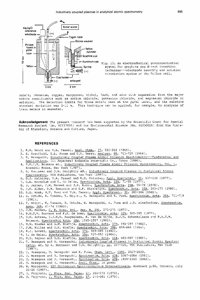
Furthermore, recently we have developed an electrochemical preconcentration system, in which analyte metals in solution are electrochemically deposited on the graphite cup shown in Fig. 10 (ref. 60). The schematic diagram of the graphite cup preconcentration system is shown in Fig. 10. In this system, analyte metal ions are electrochemically deposited by applying -2.0 V (%. Ag/AgCl reference electrode) between the electrodes (graphite cup is anode) with cir- culating the sample solution at pH 4.6. The characteristic of the present system is that analyte metals are deposited only inside the graphite cup, which is inserted directly into the plasma for simultaneous multielement determination in similar manner to the system men- tioned above. As the result, about 30-300 times preconcentration was achieved for cadmium,
lnductively coupled plasmas in analytical atomic spectrometry 695
Silicon washer
Fig. 10. An electrochemical preconcentration system for graphite cup direct insertion technique---electrode assembly and solution circulation system in the Teflon cell.
enlarged
2 crn _3 7
1 2 crn
cobalt, chromium, copper, manganese, nickel, lead, and zinc with separation from the major matrix constituents such as sodium chloride, pottasium chloride, and magnesium chloride in solution. The detection limits for those metals were at the pg/ml level, and the relative standard deviation was 2-11 %. This technique can be applied, for example, to analysis of trace metals in seawater.
Acknowledgement The present research has been supported by the Scientific Grant for Special Research Project (No. 62117005) and for Environmental Science (No. 61030026) from the Minis- try of Education, Science and Culture, Japan.
REFERENCES
1. R.H. Wendt and V.A. Fassel, Anal. Chem., 37, 920-922 (1965). 2. S. Geenfield, I . L . Jones and C.T. Berry, Analyst, 89, 713-720 (1964). 3. H. Haraguchi, Inductively Coupled Plasma Atomic Emission Spectrometrv---Fundamental and
Applications, (in Japanese) Kodansha Scientific CO., Tokyo (1986). 4. P.W.J.M. Boumans ed., Inductively Coupled Plasma Atomic Emission Spectrometry, Vol. 1,
Academic Press, New York (1987). 5. A. Montaser and D.W. Golightly ed., Inductively Coupled Plasmas in Analytical Atomic
Spectrometry, VCH Publishers, New York (1987). 6. D.J. Kalnicky, V.A. Fassel and R.N. Kniseley, Appl. Spectrosc., 31, 137-150 (1977). 7. G.R. Kornblum and L. de Galan, Spectrochim. Acta, 2, 71-96 (1977). 8. J. Jarosz, J.M. Mermet and J.P. Robin, Spectrochim. Acta, z, 55-78 (1978). 9. J.F. Alder, R.M. Bombelka and G.F. Kirkbright, Spectrochim. Acta, E, 163-175 (1980). 10. R.S. Houk, H.V. Svec and V.A. Fassel, Appl. Spectrosc., g, 380-384 (1981). 11. H. Uchida, K. Tanabe, Y. Nojiri, H. Haraguchi and K. Fuwa, Spectrochim. Acta, E, 711-718
12. Y. Nojiri, K. Tanabe, H. Uchida, H. Haraguchi, K. Fuwa and J.D. Winefordner, Spectrochim.
13. J.M. Mermet, C. R. Acad. Sci., Ser. B, 281, 273-275 (1975). 14. P.W.J.M. Boumans and F.J. de Boer, Spectrochim. Acta, 2, 365-395 (1977). 15. D.C. Schram, I.J.M.M. Raaymakers, B. van de Sijde, H.J.W. Schenkelaars and P.W.J.M.
16. M.W. Blades and G.M. Hieftje, Spectrochim. Acta, z, 191-197 (1982). 17. J.M. Milles and G.M. Hiefje, Spectrochim. Acta, E, 859-866 (1984). 18. R.J. Lovett, Spectrochim. Acta, z, 969-985 (1982). 19. L. de Galan, Spectrochim. Acta, z, 537-550 (1984). 20. G.D. Rayson and G.M. Hieftje, Spectrochim. Acta, s, 683-697 (1986). 21. T. Hasegawa and H. Haraguchi, Inductively Coupled Plasmas in Analytical Atomic Spectro-
metry, ed. by A. Montaser and D.W. Golightly, pp. 267-321, VCH Publishers, New York (1987).
(1981 1.
Acta, E, 61-74 (1983).
Boumans, Spectrochim Acta, E, 1545-1557 (1983).
22. T. Hasegawa, H. Haraguchi and K. Fuwa, Chem. Lett., 1984, 2027-2030. 23. T. Nasegawa and H. Haraguchi, Spectrochim. Acta, e, 1067-1084 (1985). 24. T. Hasegawa and H. Haraguchi, Spectrochim. Acta, e, 1505-1515 (1985). 25. T. Hasegawa and H. Haraguchi, Anal. Chem., in press 26. H. Haraguchi, XXV Colloquium Spectroscopicum Internationale, Abstract p.66, Toronto, July
27. T. Fujimoto, J. Phys. SOC. Japan, 3, 265-272 (1979). 28. T. Fujimoto, J. Phys. SOC. Japan, 47, 273-281 (1979).
21-26 (1987).
696 H. HARAGUCHI, T. HASEGAWA AND M. ABDULLAH
29. T. Fujimoto, J. Phys. SOC. Japan, 49, 1561-1568 ( 1 9 8 0 ) . 30. T. Fujimoto, J. Phys. SOC. Japan, 49, 1569-1576 ( 1 9 8 0 ) . 31. L.R. Peterson and J.E. Allen, Jr., J. Chem. Phys., 56, 6068-6076 ( 1 9 7 2 ) . 32. J.W. McConkey and F.G. Donaldson, Can. J. Phys., 2, 914-921 ( 1 9 7 3 ) . 33. A. Chutjian and D.C. Cartwright, Phys. Rev., g, 2178-2193 (1981) . 34. N.T. Padial, G.D. Meneses, F.J. da Paixao, Gy. Csanak and D.C. Cartwright, Phys. Rev.,
35. L.C. Johnson and E. Hinnov, Phys. Rev., 187, 143-152 ( 1 9 6 9 ) . 3.6. A.E. Kingston and J.E. Lauer, Proc. Phys. Soc., 87, 399-405 ( 1 9 6 6 ) . 37. A.E. Kingston and J.E. Lauer, Proc. Phys. SOC., 88, 597-603 ( 1 9 6 6 ) . 38. A. Batal, J. Jarosz and J.M. Mermet, Spectrochim. Acta. E, 983-992 ( 1 9 8 1 ) . 39. A. Batal, J. Jarosz and J.M. Mermet, Spectrochim. Acta, z, 511-516 ( 1 9 8 2 ) . 40. L.P. Hart, B.W. Smith and N. Omenetto, Spectrochim. Acta, G, 1367-1380 ( 1 9 8 6 ) . 41. G.R. Kornblum and T. Smeyers-Verbeke, Spectrochim. Acta, e, 83-87 ( 1 9 8 2 ) . 42. Z. Walker and M.W. Blades, Spectrochim. Acta,=, 761-775 ( 1 9 8 6 ) . 43. M.W. Blades and G. Horlick, Spectrochim. Acta, E, 861-880 ( 1 9 8 1 ) . 44. J.A.C. Broekaert and F. Leis, Anal. Chim. Acta, 109, 73-83 ( 1 9 7 9 ) . 45. H. Uchida, Y. Nojiri, H. Haraguchi and K. Fuwa, Anal. Chim. Acta, 123, 57-63 ( 1 9 8 1 ) . 46. K.E. Lawrence, G.W. Rice and V.A. Fassel, Anal. Chem., 56, 289-292 ( 1 9 8 4 ) . 47. H.Z. Zhuang and R.M. Barnes, Spectrochim. Acta, G, 11-19 ( 1 9 8 5 ) . 48. R.M. Dagnall, D.J. Smith, T.S. West and S. Greenfield, Anal. Chim. Acta, 54, 397-406
49. R.H. Scott, Spectrochim. Acta, z, 123-125 ( 1 9 7 8 ) . 50. M. Thompson, J.E. Goulter and F. Sieper, Analyst, 106, 32-39 ( 1 9 8 1 ) . 51. J.W. Carr and G. Horlick, Spectrochim. Acta, z, 1-15 ( 1 9 8 2 ) . 52. K.G. Ng and J.A. Caruso, Appl. Spectrosc., 2, 719- ( 1 9 8 5 ) . 53. H. Haragchi, M. Abdullah, M. Kurosawa, T. Hasegawa and K. Fuwa, Bull. Chem. SOC. Jpn., 11,
54. M. Abdullah, K. Fuwa and H. Haraguchi, Spectrochim. Acta, E, 1129-1139 ( 1 9 8 4 ) . 55. M. Abdullah and H. Haraguchi, Anal. Chem., E, 2059-2064 ( 1 9 8 5 ) . 56. E.D. Salin and G. Horlick, Anal. Chem., z, 2284-2286 ( 1 9 7 9 ) . 57. G.F. Kirkbright and S.J. Walton, Analyst, 107, 276-281 ( 1 9 8 2 ) . 58. Zhang Li-Xing, G.F. Kirkbright, M.J. Cope and J.M. Watson, Appl. Spectrosc., 31, 250-254
59. M.M. Habib and E.D. Salin, Anal. Chem., 57, 2055-2059 ( 1 9 8 5 ) . 60. M. Abdullah and H. Haraguchi, Appl. Spectrosc., 41, 715-722 ( 1 9 8 7 ) .


![SiO etching in inductively coupled C F plasmas: surface ... · Thin Solid Films 374 2000 311 .]325 SiO etching in inductively coupled C F plasmas: 226 surface chemistry and two-dimensional](https://static.documents.pub/doc/80x56/5b2aa51a7f8b9afb378b46d9/sio-etching-in-inductively-coupled-c-f-plasmas-surface-thin-solid-films.jpg)


![Heavy Quark Diffusion in Strongly Coupled Anisotropic ... · arXiv:1312.7474v1 [hep-th] 28 Dec 2013 WITS-CTP-125 Heavy Quark Diffusion in Strongly Coupled Anisotropic Plasmas Dimitrios](https://static.documents.pub/doc/80x56/5ed2a4077d90860af766acb9/heavy-quark-diiusion-in-strongly-coupled-anisotropic-arxiv13127474v1-hep-th.jpg)


