72
July 2013 Product Specification Industrial 1.8” micro SATA II SLC SSD -HERMES-ER Series- Doc-No: 100-XP8SR-JESL-01V0

July 2013
Product Specification Industrial
1.8” micro SATA II SLC SSD -HERMES-ER Series-
Doc-No: 100-XP8SR-JESL-01V0
This document is for information use only and is subject to change without prior notice. APRO Co., Ltd. assumes no
responsibility for any errors that may appear in this document, nor for incidental or consequential damages resulting from
the furnishing, performance or use of this material. No part of this document may be reproduced, transmitted, transcribed,
stored in a retrievable manner or translated into any language or computer language, in any form or by any means,
electronic, mechanical, magnetic, optical, chemical, manual or otherwise, without the prior written consent of an officer of
APRO Co., Ltd.
All parts of the APRO documentation are protected by copyright law and all rights are reserved.
APRO and the APRO logo are registered trademarks of APRO Co., Ltd.
Product names mentioned herein are for identification purposes only and may be trademarks and/or registered
trademarks of their respective companies.
© 2012 APRO Corporation. All rights reserved.
Revision History
Revision Description Date
1.0 Initial Release 2013/7/31
Contents
CONTENTS
1. INTRODUCTION ................................................................................................................................. - 4 -
1.1. SCOPE .................................................................................................................................................. - 5 - 1.2. SYSTEM FEATURES ................................................................................................................................ - 5 - 1.3. DRAM BUFFER ..................................................................................................................................... - 5 - 1.4. FLASH MANAGEMENT TECHNOLOGY - STATIC WEAR LEVELING ............................................................... - 5 - 1.5. CONFORMAL COATING ........................................................................................................................... - 6 - 1.6. BAD BLOCK MANAGEMENT .................................................................................................................... - 6 -
2. PRODUCT SPECIFICATIONS ............................................................................................................ - 7 -
2.1. SYSTEM ENVIRONMENTAL SPECIFICATIONS ............................................................................................. - 7 - 2.2. SYSTEM POWER REQUIREMENTS ........................................................................................................... - 7 - 2.3. SYSTEM PERFORMANCE ........................................................................................................................ - 7 - 2.4. SYSTEM RELIABILITY ............................................................................................................................. - 8 - 2.5. PHYSICAL SPECIFICATIONS .................................................................................................................... - 8 - 2.6. CAPACITY SPECIFICATIONS .................................................................................................................... - 9 -
3. INTERFACE DESCRIPTION ............................................................................................................. - 10 -
3.1. SATA II INTERFACE ............................................................................................................................. - 10 - 3.2. PIN ASSIGNMENTS ............................................................................................................................... - 10 -
4. COMMAND SETS ............................................................................................................................. - 11 -
4.1 ATA REGISTER ..................................................................................................................................... - 11 - 4.1.1 CHECK POWER MODE (E5H) .......................................................................................................... - 12 - 4.1.2 EXECUTE DIAGNOSITICS (90H) ..................................................................................................... - 12 - 4.1.3 IDENTIFY DEVICE (ECH).................................................................................................................. - 14 - 4.1.4 IDLE (E3H) ......................................................................................................................................... - 24 - 4.1.5 IDLE IMMEDIATE (E1H) ......................................................................................................................... - 26 - 4.1.6 S.M.A.R.T. FUNCTION (SELF-MONITORING, ANALYSIS, AND REPORTING TECHNOLOGY)......................... - 27 - 4.1.6.1 S.M.A.R.T. READ DATA (B0H WITH A FEATURE VALUE OF D0H) ........................................................ - 27 - 4.1.6.2 S.M.A.R.T. ENABLE OPERATIONS (B0H WITH A FEATURE REGISTER VALUE OF D8H) .................. - 29 -
i APRO Industrial1.8” SATA II SLC SSD built-in DDRII 512Mbits SDRAM – HERMES-ER Series © 2013 APRO Co., Ltd.
Contents
4.1.6.3 SMART DISABLE OPERATIONS (B0H WITH A FEATURE REGISTER VALUE OF D9H) ...................... - 30 - 4.1.7 READ MULTIPLE (C4H) ........................................................................................................................ - 31 - 4.1.8 READ SECTOR(S) (20H) ....................................................................................................................... - 33 - 4.1.9 READ VERIFY SECTOR (40H) ................................................................................................................ - 35 - 4.1.10 READ DMA (C8H) ............................................................................................................................... - 37 - 4.1.11 SET MULTIPLE MODE (C6H) ................................................................................................................. - 39 - 4.1.12 SET SLEEP MODE (E6H) ...................................................................................................................... - 40 - 4.1.13 FLUSH CACHE (E7H) ........................................................................................................................... - 42 - 4.1.14 STANDBY (E2H) ................................................................................................................................... - 43 - 4.1.15 STANDBY IMMEDIATE (E0H) .................................................................................................................. - 45 - 4.1.16 WRITE MULTIPLE (C5H) ....................................................................................................................... - 46 - 4.1.17 WRITE SECTOR (30H) .......................................................................................................................... - 49 - 4.1.18 WRITE DMA (CAH) ............................................................................................................................. - 51 - 4.1.19 EXECUTE DEVICE DIAGNOSTIC (90H) ................................................................................................... - 53 - 4.1.20 SECURITY SET PASSWORD (F1H) ......................................................................................................... - 54 - 4.1.21 SECURITY UNLOCK (F2H) .................................................................................................................... - 56 - 4.1.22 SECURITY ERASE PREPARE (F3H) ........................................................................................................ - 58 - 4.1.23 SECURITY ERASE UNIT (F4H) ............................................................................................................... - 59 - 4.1.24 SECURITY FREEZE LOCK (F5H) ............................................................................................................ - 62 - 4.1.25 SECURITY DISABLE PASSWORD (F6H) .................................................................................................. - 63 - 4.1.26 READ BUFFER (E4H) ........................................................................................................................... - 65 - 4.1.27 WRITE BUFFER (E8H) .......................................................................................................................... - 67 -
APPENDIX A: ORDERING INFORMATION ............................................................................................... - 69 -
1. PART NUMBER LIST ............................................................................................................................. - 69 - 2. PART NUMBER DECODER ..................................................................................................................... - 69 -
APPENDIX B: LIMITED WARRANTY ........................................................................................................ - 70 -
ii APRO Industrial1.8” SATA II SLC SSD built-in DDRII 512Mbits SDRAM – HERMES-ER Series © 2013 APRO Co., Ltd.
Contents
List of Tables TABLE 1: ENVIRONMENTAL SPECIFICATION .................................................................................................................. - 7 - TABLE 2: POWER REQUIREMENT ................................................................................................................................... - 7 - TABLE 3: SYSTEM PERFORMANCES .............................................................................................................................. - 7 - TABLE 4: SYSTEM RELIABILITY ..................................................................................................................................... - 8 - TABLE 5: PHYSICAL SPECIFICATIONS OF APRO INDUSTRIAL 1.8” MICRO SATA II SLC SSD HERMES-ER SERIES . -
8 - TABLE 6: DEVICE PARAMETERS .................................................................................................................................... - 9 - TABLE 7: PIN ASSIGNMENTS........................................................................................................................................ - 10 - TABLE 8: ATA COMMAND TABLE ................................................................................................................................ - 11 -
List of Figures FIGURE 1: APRO INDUSTRIAL 1.8” MICRO SATA II SLC SSD HERMES-ER SERIES SYSTEM BLOCK DIAGRAM .. - 4 - FIGURE 2: APRO INDUSTRIAL 1.8” MICRO SATA II SLC SSD HERMES-ER SERIES DIMENSION .......................... - 9 - FIGURE 3: THE CONNECTORS OF 1.8” MICRO SATA II SLC SSD ............................................................................. - 10 -
iii APRO Industrial1.8” SATA II SLC SSD built-in DDRII 512Mbits SDRAM – HERMES-ER Series © 2013 APRO Co., Ltd.
Product Specification
1. Introduction
APRO Industrial 1.8” micro SATA II SLC SSD HERMES-ER Series provide high capacity flash memory Solid State Drive
(SSD) that electrically complies with Serial ATA 2.6 (SATA) standard and supports SATA Gen-II (3.0 GB/s) with high
performance. The main used flash memories are SLC-NAND type flash memory chips. The available disk capacities are
8GB, 16GB, 32GB, 64GB and 128GB.
The operating temperature grade is optional for commercial grade 0°C ~ 70°C and Industrial grade with special conformal
coating treatment on PCBA completely which may support operating temperature -40°C ~ +85°C. Trim command supports
under Windows 7, which improves SSD performance. The sequential read is up to 203.3 MB/sec, and sequential write is
up to 107.8 MB/sec.
The APRO Industrial 1.8” micro SATA II SLC SSD built-in DDRII 512Mbits SDRAM products provide a high level interface
to the host computer. It is native design to provide higher bandwidth for flash memory access. Each sector is protected by
a powerful 24 bits per 512 bytes block error correction (ECC). APRO Industrial 1.8” micro SATA II SLC SSD HERMES-ER
Series intelligent controller manages interface protocols, data storage and retrieval as well as ECC, defect handling and
diagnostics, power management and clock control.
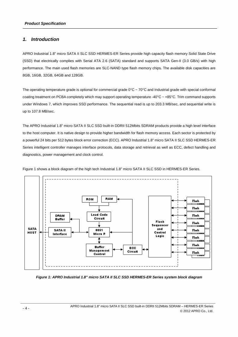
Figure 1 shows a block diagram of the high tech Industrial 1.8” micro SATA II SLC SSD in HERMES-ER Series.
Figure 1: APRO Industrial 1.8” micro SATA II SLC SSD HERMES-ER Series system block diagram
- 4 - APRO Industrial 1.8” micro SATA II SLC SSD built-in DDRII 512Mbits SDRAM – HERMES-ER Series © 2012 APRO Co., Ltd.
Product Specification
1.1. Scope This document describes the features and specifications and installation guide of APRO’s Industrial 1.8” micro SATA II
SLC SSDs – HERMES-ER Series. In the appendix, there provides order information, warranty policy, RMA/DOA
procedure for the most convenient reference.
1.2. System Features SLC-NAND type flash technology
1.8” form-factor ( shorter than PCMCIA Type II form-factor)
Micro SATA 7 pins (data) + 9 pins (power connector) interface
ATA/ATAPI-8 compliant
SATA 1.0a and SATA 2.6 specification compliance
SMART (Self-Monitoring, Analysis and Reporting Technology) function supported.
Supports Window-7 TRIM Command
Non-volatile memory and no moving parts
SLC Flash SSD capacity in 8GB, 16GB, 32GB, 64GB and 128GB
Sequential read performance up to 203.3 MB/sec (Max.)
Sequential write performance up to 107.8 MB/sec (Max.)
Automatic 24 bits per 512 bytes block error correction (ECC) and retry capabilities
+3.3V or +5 V ±5% Power input voltage.
Shock : 1,500G, compliance to MIL-STD-810F
Vibration : 15G, compliance to MIL-STD-810F
Very high performance, very low power consumption
Low weight, Noiseless
1.3. DRAM Buffer SSDs designed with a 512Mbits DDRII SDRAM buffer which is support high transfer rate as a data buffer for the SSD;
SSD with SDRAM buffer is able to deliver excellent random data transfer speed.
1.4. Flash Management Technology - Static Wear Leveling In order to gain the best management for flash memory, APRO 1.8” micro SATA II SLC SSD HERMES-ER Series supports
Static Wear-leveling technology to manage the Flash system. The life of flash memory is limited; the management is to
increase the life of the flash product.
A static wear-leveling algorithm evenly distributes data over an entire Flash cell array and searches for the least used
physical blocks. The identified low cycled sectors are used to write the data to those locations. If blocks are empty, the
write occurs normally. If blocks contain static data, it moves that data to a more heavily used location before it moves the
newly written data. The static wear leveling maximizes effective endurance Flash array compared to no wear leveling or
dynamic wear leveling.
- 5 - APRO Industrial 1.8” micro SATA II SLC SSD built-in DDRII 512Mbits SDRAM – HERMES-ER Series © 2012 APRO Co., Ltd.
Product Specification
1.5. Conformal Coating Conformal coating is a protective, dielectric coating designed to conform to the surface of an assembled printed circuit
board. Commonly used conformal coatings include silicone, acrylic, urethane and epoxy. APRO applies only silicone on
APRO storages products upon requested especially by customers. The type of silicone coating features good thermal
shock resistance due to flexibility. It is also easy to apply and repair.
Conformal coating offers protection of circuitry from moisture, fungus, dust and corrosion caused by extreme
environments. It also prevents damage from those Flash storages handling during construction, installation and use, and
reduces mechanical stress on components and protects from thermal shock. The greatest advantage of conformal coating
is to allow greater component density due to increased dielectric strength between conductors.
APRO apply MIL-I-46058C silicon conformal coating.
1.6. Bad Block Management Bad blocks of NAND flash may accumulate up to 2% of entire number of blocks during its manufacturing process and
during the flash operational usage.
A system must be able to recognize bad block(s) based on the original bad block information and create a bad block table
to keep track of blocks that fail during use. The first block of NAND Flash (block 0) is guaranteed to be good. The bad
block information is stored in the reservoir area that is located in the highest address region of the NAND flash. Once the
bad blocks have been located, and the bad blocks be no longer accessed.
To locate the bad blocks on a brand new device, read out each block. Any block that is not all FFFFh in 1st sector of 1st or
2nd page in a spare area is a bad block. Although random bit errors may occur during use, this does not necessarily
mean that a block is bad. Generally, a block should be marked as bad only when there is a problem or erase failure. This
can be determined by doing a status read after erase/program operation. The flash memory is initialized by formatting
the flash memory into a reserved area and user area.
In order to detect the initial bad blocks to handle run time bad blocks, APRO HERMES Series’ SSD provides the Bad
Block Management scheme. It remaps a bad block to one of the reserved blocks so that the data contained in one bad
block is not lost and new data writes on a bad block is avoided.
- 6 - APRO Industrial 1.8” micro SATA II SLC SSD built-in DDRII 512Mbits SDRAM – HERMES-ER Series © 2012 APRO Co., Ltd.
Product Specification
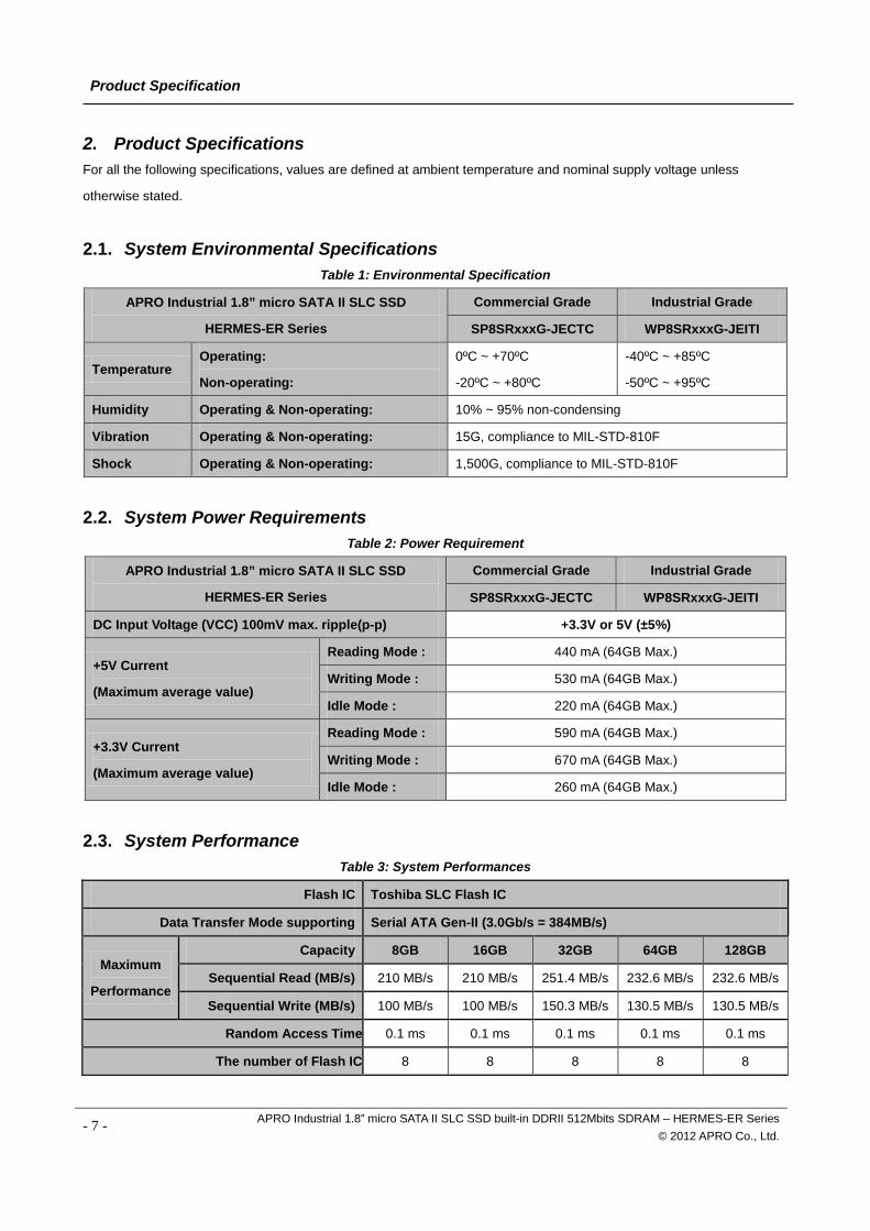
2. Product Specifications For all the following specifications, values are defined at ambient temperature and nominal supply voltage unless
otherwise stated.
2.1. System Environmental Specifications Table 1: Environmental Specification
APRO Industrial 1.8” micro SATA II SLC SSD
HERMES-ER Series
Commercial Grade Industrial Grade
SP8SRxxxG-JECTC WP8SRxxxG-JEITI
Temperature Operating:
Non-operating:
0ºC ~ +70ºC
-20ºC ~ +80ºC
-40ºC ~ +85ºC
-50ºC ~ +95ºC
Humidity Operating & Non-operating: 10% ~ 95% non-condensing
Vibration Operating & Non-operating: 15G, compliance to MIL-STD-810F
Shock Operating & Non-operating: 1,500G, compliance to MIL-STD-810F
2.2. System Power Requirements Table 2: Power Requirement
APRO Industrial 1.8” micro SATA II SLC SSD
HERMES-ER Series
Commercial Grade Industrial Grade
SP8SRxxxG-JECTC WP8SRxxxG-JEITI
DC Input Voltage (VCC) 100mV max. ripple(p-p) +3.3V or 5V (±5%)
+5V Current
(Maximum average value)
Reading Mode : 440 mA (64GB Max.)
Writing Mode : 530 mA (64GB Max.)
Idle Mode : 220 mA (64GB Max.)
+3.3V Current
(Maximum average value)
Reading Mode : 590 mA (64GB Max.)
Writing Mode : 670 mA (64GB Max.)
Idle Mode : 260 mA (64GB Max.)
2.3. System Performance Table 3: System Performances
Flash IC Toshiba SLC Flash IC
Data Transfer Mode supporting Serial ATA Gen-II (3.0Gb/s = 384MB/s)
Maximum
Performance
Capacity 8GB 16GB 32GB 64GB 128GB
Sequential Read (MB/s) 210 MB/s 210 MB/s 251.4 MB/s 232.6 MB/s 232.6 MB/s
Sequential Write (MB/s) 100 MB/s 100 MB/s 150.3 MB/s 130.5 MB/s 130.5 MB/s
Random Access Time 0.1 ms 0.1 ms 0.1 ms 0.1 ms 0.1 ms The number of Flash IC 8 8 8 8 8
- 7 - APRO Industrial 1.8” micro SATA II SLC SSD built-in DDRII 512Mbits SDRAM – HERMES-ER Series © 2012 APRO Co., Ltd.
Product Specification
Note:
(1). All values quoted are typically at 25℃ and nominal supply voltage.
(2). Testing of the Industrial 1.8” micro SATA II SLC SSD maximum performance was performed under the following platform:
- Computer with AMD 3.0GHz processor
- Windows XP Professional operating system
(3). Above performance data are for reference only for the performance would be different for various factors such like flash memory
chips, system configurations, OS and software for performance testing,…etc.
2.4. System Reliability Table 4: System Reliability
Wear-leveling Algorithms Static Wear-leveling
Bad Blocks Management Supportive
ECC Technology 24 bits per 512 bytes block
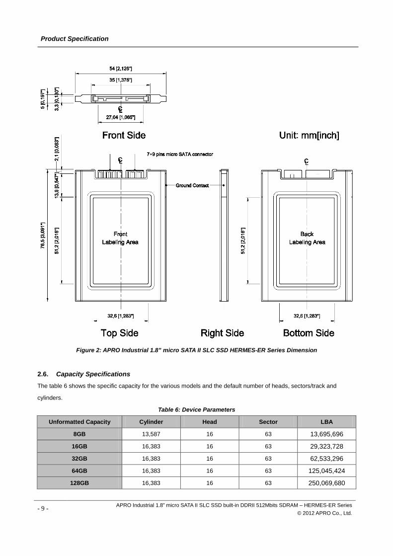
2.5. Physical Specifications
Refer to Table 5 and see Figure 2 for Industrial 1.8” micro SATA II SLC SSD HERMES-ER Series physical specifications
and dimensions.
Table 5: Physical Specifications of APRO Industrial 1.8” micro SATA II SLC SSD HERMES-ER Series
Capacity: 256GB
Length: 78.5 + 0.30mm / 3.09 in
Width: 54 + 0.20mm / 2.13 in
Thickness: 5 + 0.15mm / 0.20 in
Weight: 25g + 5g / 0.88oz
- 8 - APRO Industrial 1.8” micro SATA II SLC SSD built-in DDRII 512Mbits SDRAM – HERMES-ER Series © 2012 APRO Co., Ltd.
Product Specification
Figure 2: APRO Industrial 1.8” micro SATA II SLC SSD HERMES-ER Series Dimension
2.6. Capacity Specifications
The table 6 shows the specific capacity for the various models and the default number of heads, sectors/track and
cylinders.
Table 6: Device Parameters
Unformatted Capacity Cylinder Head Sector LBA
8GB 13,587 16 63 13,695,696
16GB 16,383 16 63 29,323,728
32GB 16,383 16 63 62,533,296
64GB 16,383 16 63 125,045,424
128GB 16,383 16 63 250,069,680
- 9 - APRO Industrial 1.8” micro SATA II SLC SSD built-in DDRII 512Mbits SDRAM – HERMES-ER Series
© 2012 APRO Co., Ltd.
Product Specification
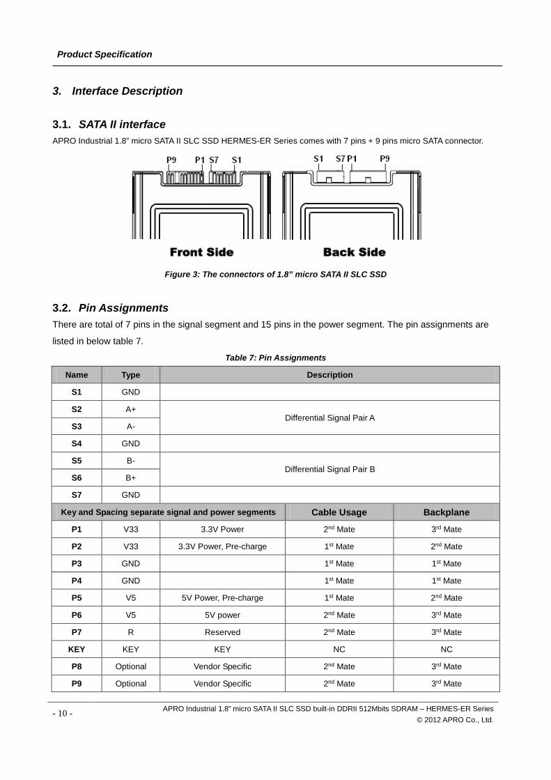
3. Interface Description 3.1. SATA II interface APRO Industrial 1.8” micro SATA II SLC SSD HERMES-ER Series comes with 7 pins + 9 pins micro SATA connector.
Figure 3: The connectors of 1.8” micro SATA II SLC SSD
3.2. Pin Assignments There are total of 7 pins in the signal segment and 15 pins in the power segment. The pin assignments are
listed in below table 7.
Table 7: Pin Assignments
Name Type Description
S1 GND
S2 A+ Differential Signal Pair A
S3 A-
S4 GND
S5 B- Differential Signal Pair B
S6 B+
S7 GND
Key and Spacing separate signal and power segments Cable Usage Backplane
P1 V33 3.3V Power 2nd Mate 3rd Mate
P2 V33 3.3V Power, Pre-charge 1st Mate 2nd Mate
P3 GND 1st Mate 1st Mate
P4 GND 1st Mate 1st Mate
P5 V5 5V Power, Pre-charge 1st Mate 2nd Mate
P6 V5 5V power 2nd Mate 3rd Mate
P7 R Reserved 2nd Mate 3rd Mate
KEY KEY KEY NC NC
P8 Optional Vendor Specific 2nd Mate 3rd Mate
P9 Optional Vendor Specific 2nd Mate 3rd Mate
- 10 - APRO Industrial 1.8” micro SATA II SLC SSD built-in DDRII 512Mbits SDRAM – HERMES-ER Series © 2012 APRO Co., Ltd.
Product Specification
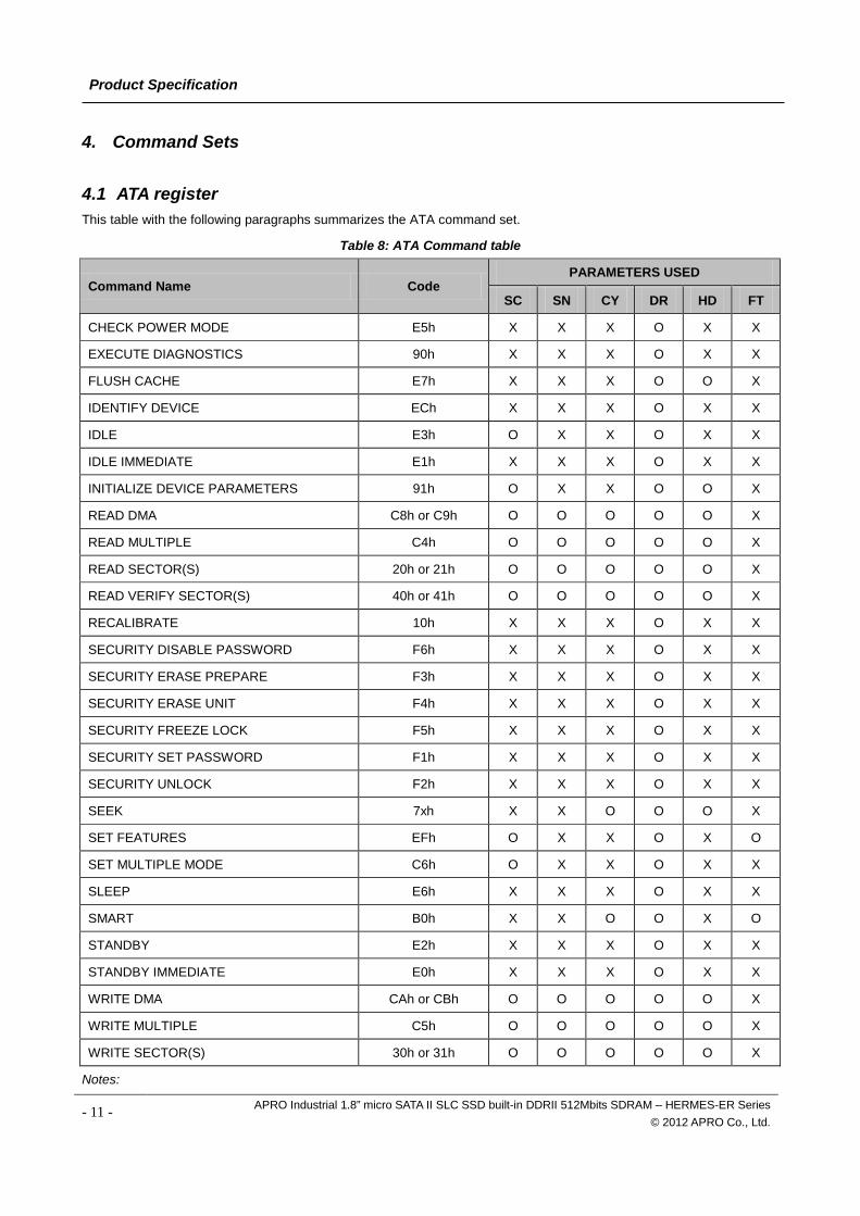
4. Command Sets 4.1 ATA register This table with the following paragraphs summarizes the ATA command set.
Table 8: ATA Command table
Command Name Code PARAMETERS USED
SC SN CY DR HD FT
CHECK POWER MODE E5h X X X O X X
EXECUTE DIAGNOSTICS 90h X X X O X X
FLUSH CACHE E7h X X X O O X
IDENTIFY DEVICE ECh X X X O X X
IDLE E3h O X X O X X
IDLE IMMEDIATE E1h X X X O X X
INITIALIZE DEVICE PARAMETERS 91h O X X O O X
READ DMA C8h or C9h O O O O O X
READ MULTIPLE C4h O O O O O X
READ SECTOR(S) 20h or 21h O O O O O X
READ VERIFY SECTOR(S) 40h or 41h O O O O O X
RECALIBRATE 10h X X X O X X
SECURITY DISABLE PASSWORD F6h X X X O X X
SECURITY ERASE PREPARE F3h X X X O X X
SECURITY ERASE UNIT F4h X X X O X X
SECURITY FREEZE LOCK F5h X X X O X X
SECURITY SET PASSWORD F1h X X X O X X
SECURITY UNLOCK F2h X X X O X X
SEEK 7xh X X O O O X
SET FEATURES EFh O X X O X O
SET MULTIPLE MODE C6h O X X O X X
SLEEP E6h X X X O X X
SMART B0h X X O O X O
STANDBY E2h X X X O X X
STANDBY IMMEDIATE E0h X X X O X X
WRITE DMA CAh or CBh O O O O O X
WRITE MULTIPLE C5h O O O O O X
WRITE SECTOR(S) 30h or 31h O O O O O X
Notes:
- 11 - APRO Industrial 1.8” micro SATA II SLC SSD built-in DDRII 512Mbits SDRAM – HERMES-ER Series © 2012 APRO Co., Ltd.
Product Specification
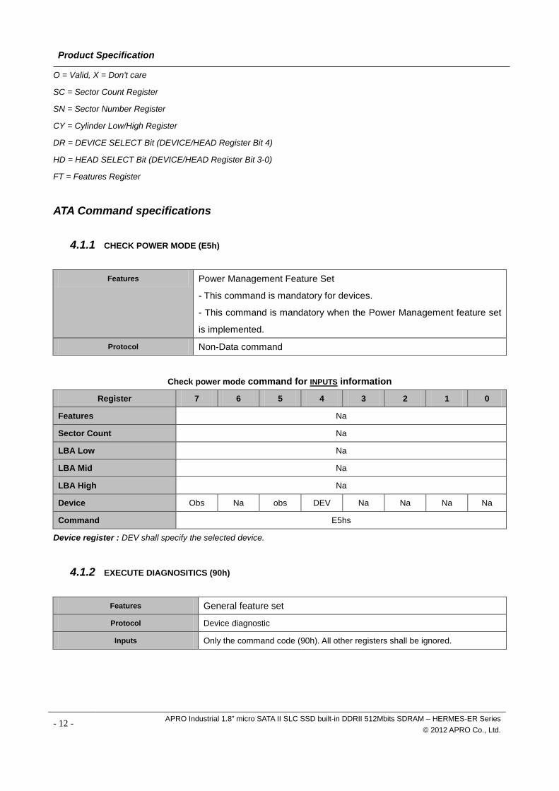
O = Valid, X = Don't care
SC = Sector Count Register
SN = Sector Number Register
CY = Cylinder Low/High Register
DR = DEVICE SELECT Bit (DEVICE/HEAD Register Bit 4)
HD = HEAD SELECT Bit (DEVICE/HEAD Register Bit 3-0)
FT = Features Register
ATA Command specifications
4.1.1 CHECK POWER MODE (E5h)
Features Power Management Feature Set
- This command is mandatory for devices.
- This command is mandatory when the Power Management feature set
is implemented.
Protocol Non-Data command
Check power mode command for INPUTS information
Register 7 6 5 4 3 2 1 0
Features Na
Sector Count Na
LBA Low Na
LBA Mid Na
LBA High Na
Device Obs Na obs DEV Na Na Na Na
Command E5hs
Device register : DEV shall specify the selected device.
4.1.2 EXECUTE DIAGNOSITICS (90h)
Features General feature set
Protocol Device diagnostic
Inputs Only the command code (90h). All other registers shall be ignored.
- 12 - APRO Industrial 1.8” micro SATA II SLC SSD built-in DDRII 512Mbits SDRAM – HERMES-ER Series © 2012 APRO Co., Ltd.
Product Specification
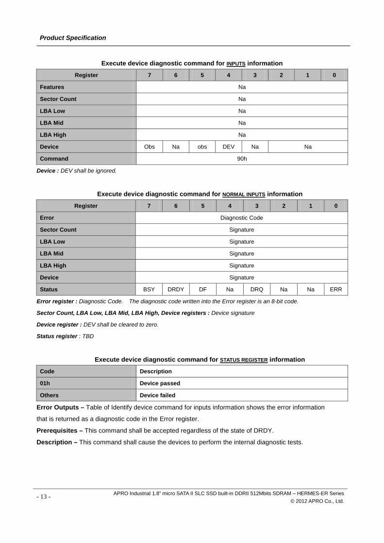
Execute device diagnostic command for INPUTS information
Register 7 6 5 4 3 2 1 0
Features Na
Sector Count Na
LBA Low Na
LBA Mid Na
LBA High Na
Device Obs Na obs DEV Na Na
Command 90h
Device : DEV shall be ignored.
Execute device diagnostic command for NORMAL INPUTS information
Register 7 6 5 4 3 2 1 0
Error Diagnostic Code
Sector Count Signature
LBA Low Signature
LBA Mid Signature
LBA High Signature
Device Signature
Status BSY DRDY DF Na DRQ Na Na ERR
Error register : Diagnostic Code. The diagnostic code written into the Error register is an 8-bit code.
Sector Count, LBA Low, LBA Mid, LBA High, Device registers : Device signature
Device register : DEV shall be cleared to zero.
Status register : TBD
Execute device diagnostic command for STATUS REGISTER information
Code Description
01h Device passed
Others Device failed
Error Outputs – Table of Identify device command for inputs information shows the error information
that is returned as a diagnostic code in the Error register.
Prerequisites – This command shall be accepted regardless of the state of DRDY.
Description – This command shall cause the devices to perform the internal diagnostic tests.
- 13 - APRO Industrial 1.8” micro SATA II SLC SSD built-in DDRII 512Mbits SDRAM – HERMES-ER Series © 2012 APRO Co., Ltd.
Product Specification
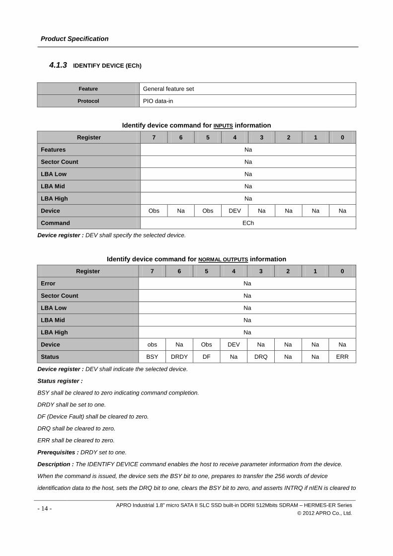
4.1.3 IDENTIFY DEVICE (ECh)
Feature General feature set
Protocol PIO data-in
Identify device command for INPUTS information
Register 7 6 5 4 3 2 1 0
Features Na
Sector Count Na
LBA Low Na
LBA Mid Na
LBA High Na
Device Obs Na Obs DEV Na Na Na Na
Command ECh
Device register : DEV shall specify the selected device.
Identify device command for NORMAL OUTPUTS information
Register 7 6 5 4 3 2 1 0
Error Na
Sector Count Na
LBA Low Na
LBA Mid Na
LBA High Na
Device obs Na Obs DEV Na Na Na Na
Status BSY DRDY DF Na DRQ Na Na ERR
Device register : DEV shall indicate the selected device.
Status register :
BSY shall be cleared to zero indicating command completion.
DRDY shall be set to one.
DF (Device Fault) shall be cleared to zero.
DRQ shall be cleared to zero.
ERR shall be cleared to zero.
Prerequisites : DRDY set to one.
Description : The IDENTIFY DEVICE command enables the host to receive parameter information from the device.
When the command is issued, the device sets the BSY bit to one, prepares to transfer the 256 words of device
identification data to the host, sets the DRQ bit to one, clears the BSY bit to zero, and asserts INTRQ if nIEN is cleared to
- 14 - APRO Industrial 1.8” micro SATA II SLC SSD built-in DDRII 512Mbits SDRAM – HERMES-ER Series © 2012 APRO Co., Ltd.
Product Specification
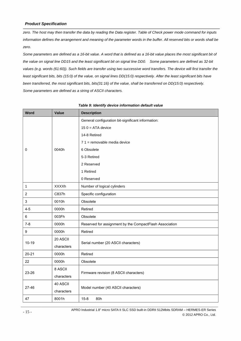
zero. The host may then transfer the data by reading the Data register. Table of Check power mode command for inputs
information defines the arrangement and meaning of the parameter words in the buffer. All reserved bits or words shall be
zero.
Some parameters are defined as a 16-bit value. A word that is defined as a 16-bit value places the most significant bit of
the value on signal line DD15 and the least significant bit on signal line DD0. Some parameters are defined as 32-bit
values (e.g. words (61:60)). Such fields are transfer using two successive word transfers. The device will first transfer the
least significant bits, bits (15:0) of the value, on signal lines DD(15:0) respectively. After the least significant bits have
been transferred, the most significant bits, bits(31:16) of the value, shall be transferred on DD(15:0) respectively.
Some parameters are defined as a string of ASCII characters.
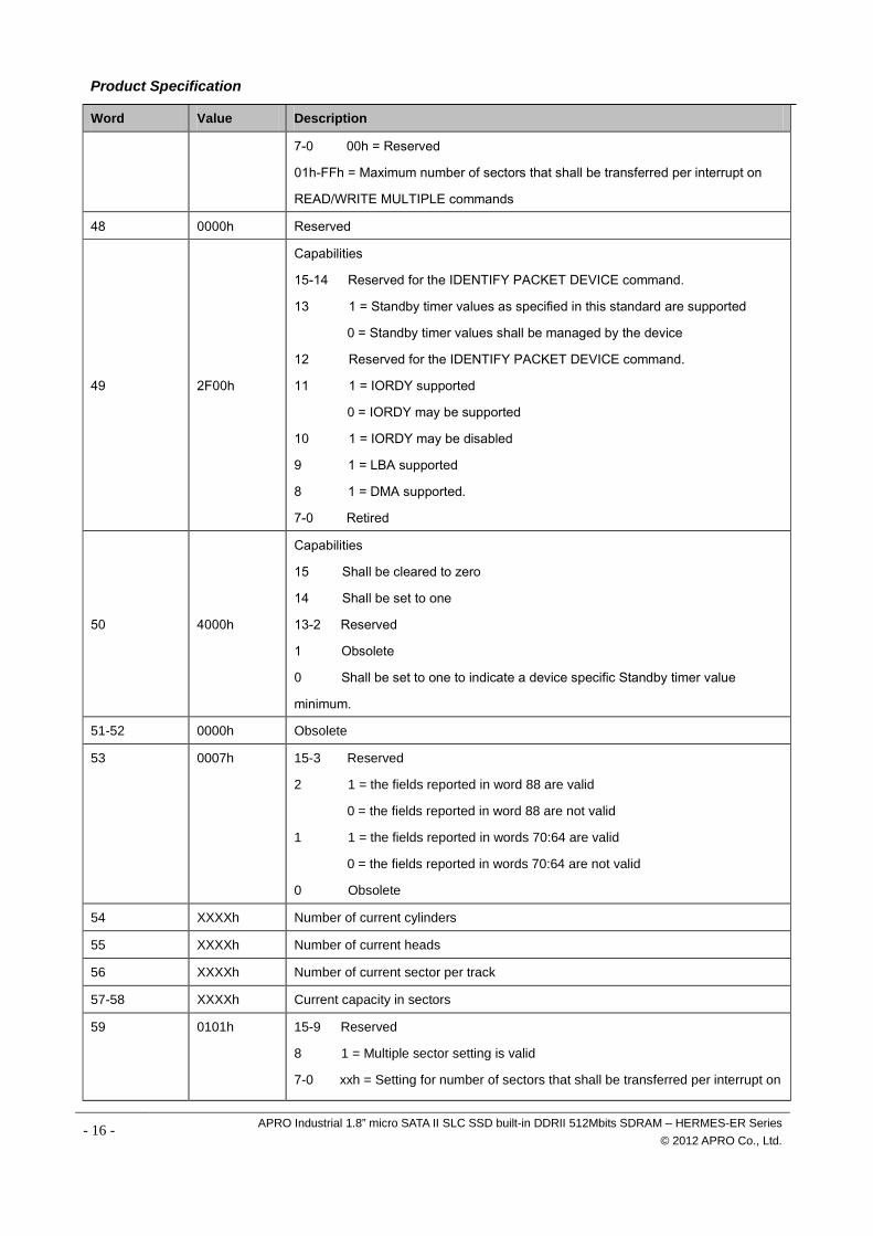
Table 9: Identify device information default value
Word Value Description
0 0040h
General configuration bit-significant information:
15 0 = ATA device
14-8 Retired
7 1 = removable media device
6 Obsolete
5-3 Retired
2 Reserved
1 Retired
0 Reserved
1 XXXXh Number of logical cylinders
2 C837h Specific configuration
3 0010h Obsolete
4-5 0000h Retired
6 003Fh Obsolete
7-8 0000h Reserved for assignment by the CompactFlash Association
9 0000h Retired
10-19 20 ASCII
characters Serial number (20 ASCII characters)
20-21 0000h Retired
22 0000h Obsolete
23-26 8 ASCII
characters Firmware revision (8 ASCII characters)
27-46 40 ASCII
characters Model number (40 ASCII characters)
47 8001h 15-8 80h
- 15 - APRO Industrial 1.8” micro SATA II SLC SSD built-in DDRII 512Mbits SDRAM – HERMES-ER Series © 2012 APRO Co., Ltd.
Product Specification
Word Value Description
7-0 00h = Reserved
01h-FFh = Maximum number of sectors that shall be transferred per interrupt on
READ/WRITE MULTIPLE commands
48 0000h Reserved
49 2F00h
Capabilities
15-14 Reserved for the IDENTIFY PACKET DEVICE command.
13 1 = Standby timer values as specified in this standard are supported
0 = Standby timer values shall be managed by the device
12 Reserved for the IDENTIFY PACKET DEVICE command.
11 1 = IORDY supported
0 = IORDY may be supported
10 1 = IORDY may be disabled
9 1 = LBA supported
8 1 = DMA supported.
7-0 Retired
50 4000h
Capabilities
15 Shall be cleared to zero
14 Shall be set to one
13-2 Reserved
1 Obsolete
0 Shall be set to one to indicate a device specific Standby timer value
minimum.
51-52 0000h Obsolete
53 0007h 15-3 Reserved
2 1 = the fields reported in word 88 are valid
0 = the fields reported in word 88 are not valid
1 1 = the fields reported in words 70:64 are valid
0 = the fields reported in words 70:64 are not valid
0 Obsolete
54 XXXXh Number of current cylinders
55 XXXXh Number of current heads
56 XXXXh Number of current sector per track
57-58 XXXXh Current capacity in sectors
59 0101h 15-9 Reserved
8 1 = Multiple sector setting is valid
7-0 xxh = Setting for number of sectors that shall be transferred per interrupt on
- 16 - APRO Industrial 1.8” micro SATA II SLC SSD built-in DDRII 512Mbits SDRAM – HERMES-ER Series © 2012 APRO Co., Ltd.
Product Specification
Word Value Description
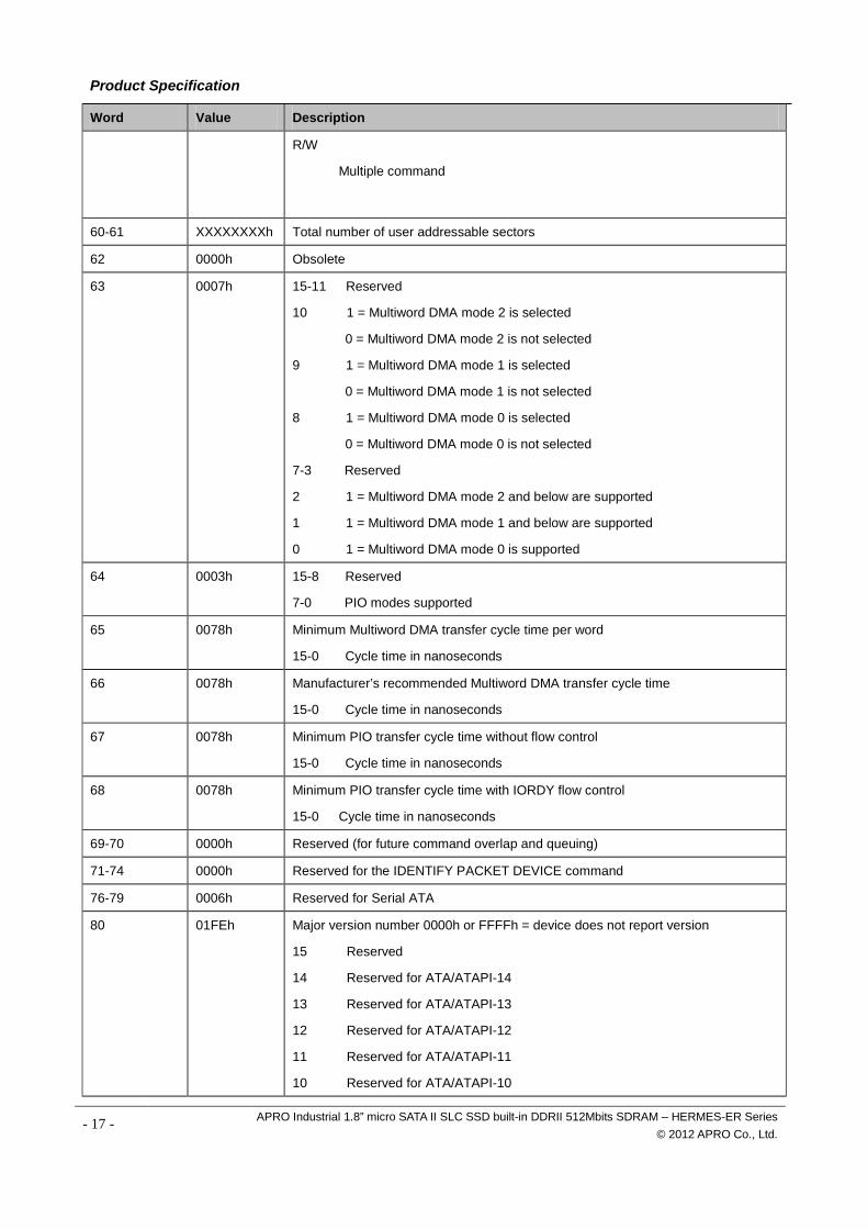
R/W
Multiple command
60-61 XXXXXXXXh Total number of user addressable sectors
62 0000h Obsolete
63 0007h 15-11 Reserved
10 1 = Multiword DMA mode 2 is selected
0 = Multiword DMA mode 2 is not selected
9 1 = Multiword DMA mode 1 is selected
0 = Multiword DMA mode 1 is not selected
8 1 = Multiword DMA mode 0 is selected
0 = Multiword DMA mode 0 is not selected
7-3 Reserved
2 1 = Multiword DMA mode 2 and below are supported
1 1 = Multiword DMA mode 1 and below are supported
0 1 = Multiword DMA mode 0 is supported
64 0003h 15-8 Reserved
7-0 PIO modes supported
65 0078h Minimum Multiword DMA transfer cycle time per word
15-0 Cycle time in nanoseconds
66 0078h Manufacturer’s recommended Multiword DMA transfer cycle time
15-0 Cycle time in nanoseconds
67 0078h Minimum PIO transfer cycle time without flow control
15-0 Cycle time in nanoseconds
68 0078h Minimum PIO transfer cycle time with IORDY flow control
15-0 Cycle time in nanoseconds
69-70 0000h Reserved (for future command overlap and queuing)
71-74 0000h Reserved for the IDENTIFY PACKET DEVICE command
76-79 0006h Reserved for Serial ATA
80 01FEh Major version number 0000h or FFFFh = device does not report version
15 Reserved
14 Reserved for ATA/ATAPI-14
13 Reserved for ATA/ATAPI-13
12 Reserved for ATA/ATAPI-12
11 Reserved for ATA/ATAPI-11
10 Reserved for ATA/ATAPI-10
- 17 - APRO Industrial 1.8” micro SATA II SLC SSD built-in DDRII 512Mbits SDRAM – HERMES-ER Series © 2012 APRO Co., Ltd.
Product Specification
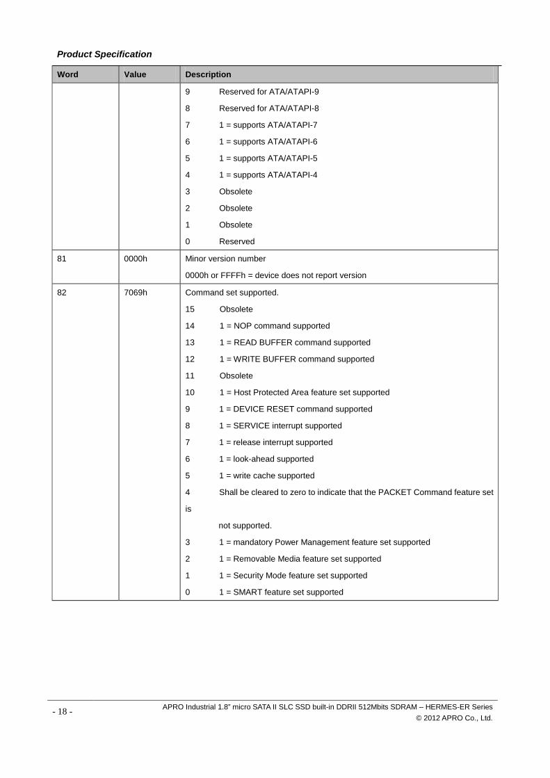
Word Value Description
9 Reserved for ATA/ATAPI-9
8 Reserved for ATA/ATAPI-8
7 1 = supports ATA/ATAPI-7
6 1 = supports ATA/ATAPI-6
5 1 = supports ATA/ATAPI-5
4 1 = supports ATA/ATAPI-4
3 Obsolete
2 Obsolete
1 Obsolete
0 Reserved
81 0000h Minor version number
0000h or FFFFh = device does not report version
82 7069h Command set supported.
15 Obsolete
14 1 = NOP command supported
13 1 = READ BUFFER command supported
12 1 = WRITE BUFFER command supported
11 Obsolete
10 1 = Host Protected Area feature set supported
9 1 = DEVICE RESET command supported
8 1 = SERVICE interrupt supported
7 1 = release interrupt supported
6 1 = look-ahead supported
5 1 = write cache supported
4 Shall be cleared to zero to indicate that the PACKET Command feature set
is
not supported.
3 1 = mandatory Power Management feature set supported
2 1 = Removable Media feature set supported
1 1 = Security Mode feature set supported
0 1 = SMART feature set supported
- 18 - APRO Industrial 1.8” micro SATA II SLC SSD built-in DDRII 512Mbits SDRAM – HERMES-ER Series © 2012 APRO Co., Ltd.
Product Specification
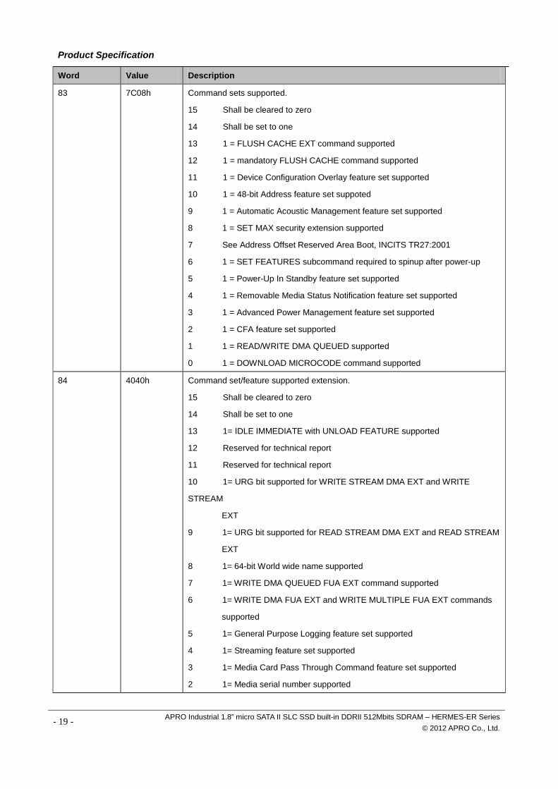
Word Value Description
83 7C08h Command sets supported.
15 Shall be cleared to zero
14 Shall be set to one
13 1 = FLUSH CACHE EXT command supported
12 1 = mandatory FLUSH CACHE command supported
11 1 = Device Configuration Overlay feature set supported
10 1 = 48-bit Address feature set suppoted
9 1 = Automatic Acoustic Management feature set supported
8 1 = SET MAX security extension supported
7 See Address Offset Reserved Area Boot, INCITS TR27:2001
6 1 = SET FEATURES subcommand required to spinup after power-up
5 1 = Power-Up In Standby feature set supported
4 1 = Removable Media Status Notification feature set supported
3 1 = Advanced Power Management feature set supported
2 1 = CFA feature set supported
1 1 = READ/WRITE DMA QUEUED supported
0 1 = DOWNLOAD MICROCODE command supported
84 4040h Command set/feature supported extension.
15 Shall be cleared to zero
14 Shall be set to one
13 1= IDLE IMMEDIATE with UNLOAD FEATURE supported
12 Reserved for technical report
11 Reserved for technical report
10 1= URG bit supported for WRITE STREAM DMA EXT and WRITE
STREAM
EXT
9 1= URG bit supported for READ STREAM DMA EXT and READ STREAM
EXT
8 1= 64-bit World wide name supported
7 1= WRITE DMA QUEUED FUA EXT command supported
6 1= WRITE DMA FUA EXT and WRITE MULTIPLE FUA EXT commands
supported
5 1= General Purpose Logging feature set supported
4 1= Streaming feature set supported
3 1= Media Card Pass Through Command feature set supported
2 1= Media serial number supported
- 19 - APRO Industrial 1.8” micro SATA II SLC SSD built-in DDRII 512Mbits SDRAM – HERMES-ER Series © 2012 APRO Co., Ltd.
Product Specification
Word Value Description
1 1 = SMART self-test supported
0 1 = SMART error logging supported
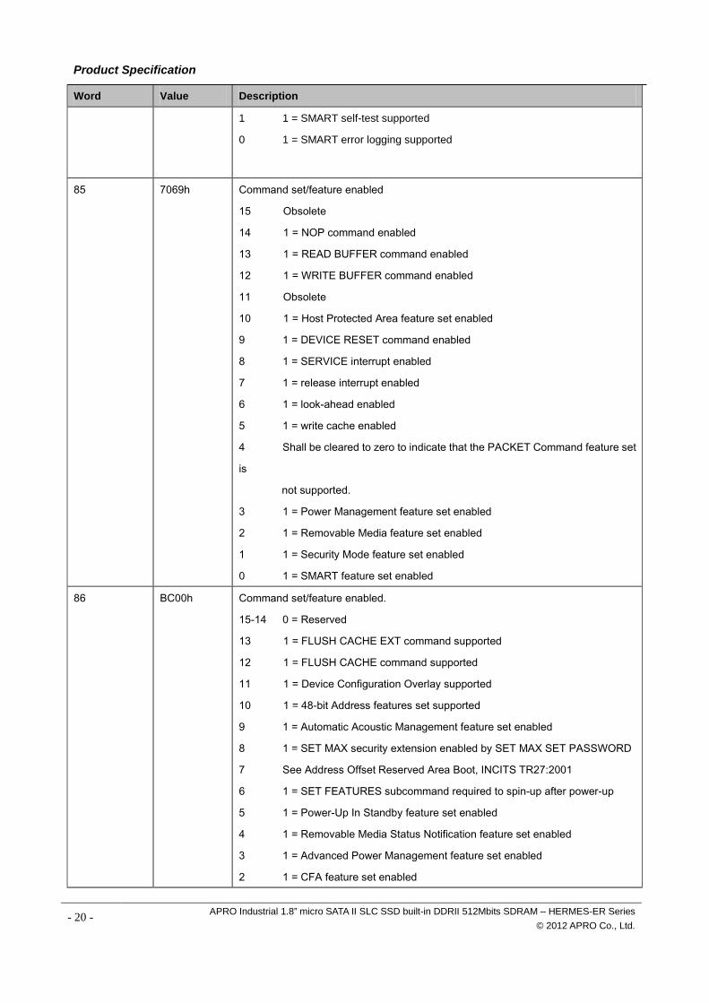
85 7069h Command set/feature enabled
15 Obsolete
14 1 = NOP command enabled
13 1 = READ BUFFER command enabled
12 1 = WRITE BUFFER command enabled
11 Obsolete
10 1 = Host Protected Area feature set enabled
9 1 = DEVICE RESET command enabled
8 1 = SERVICE interrupt enabled
7 1 = release interrupt enabled
6 1 = look-ahead enabled
5 1 = write cache enabled
4 Shall be cleared to zero to indicate that the PACKET Command feature set
is
not supported.
3 1 = Power Management feature set enabled
2 1 = Removable Media feature set enabled
1 1 = Security Mode feature set enabled
0 1 = SMART feature set enabled
86 BC00h Command set/feature enabled.
15-14 0 = Reserved
13 1 = FLUSH CACHE EXT command supported
12 1 = FLUSH CACHE command supported
11 1 = Device Configuration Overlay supported
10 1 = 48-bit Address features set supported
9 1 = Automatic Acoustic Management feature set enabled
8 1 = SET MAX security extension enabled by SET MAX SET PASSWORD
7 See Address Offset Reserved Area Boot, INCITS TR27:2001
6 1 = SET FEATURES subcommand required to spin-up after power-up
5 1 = Power-Up In Standby feature set enabled
4 1 = Removable Media Status Notification feature set enabled
3 1 = Advanced Power Management feature set enabled
2 1 = CFA feature set enabled
- 20 - APRO Industrial 1.8” micro SATA II SLC SSD built-in DDRII 512Mbits SDRAM – HERMES-ER Series © 2012 APRO Co., Ltd.
Product Specification
Word Value Description
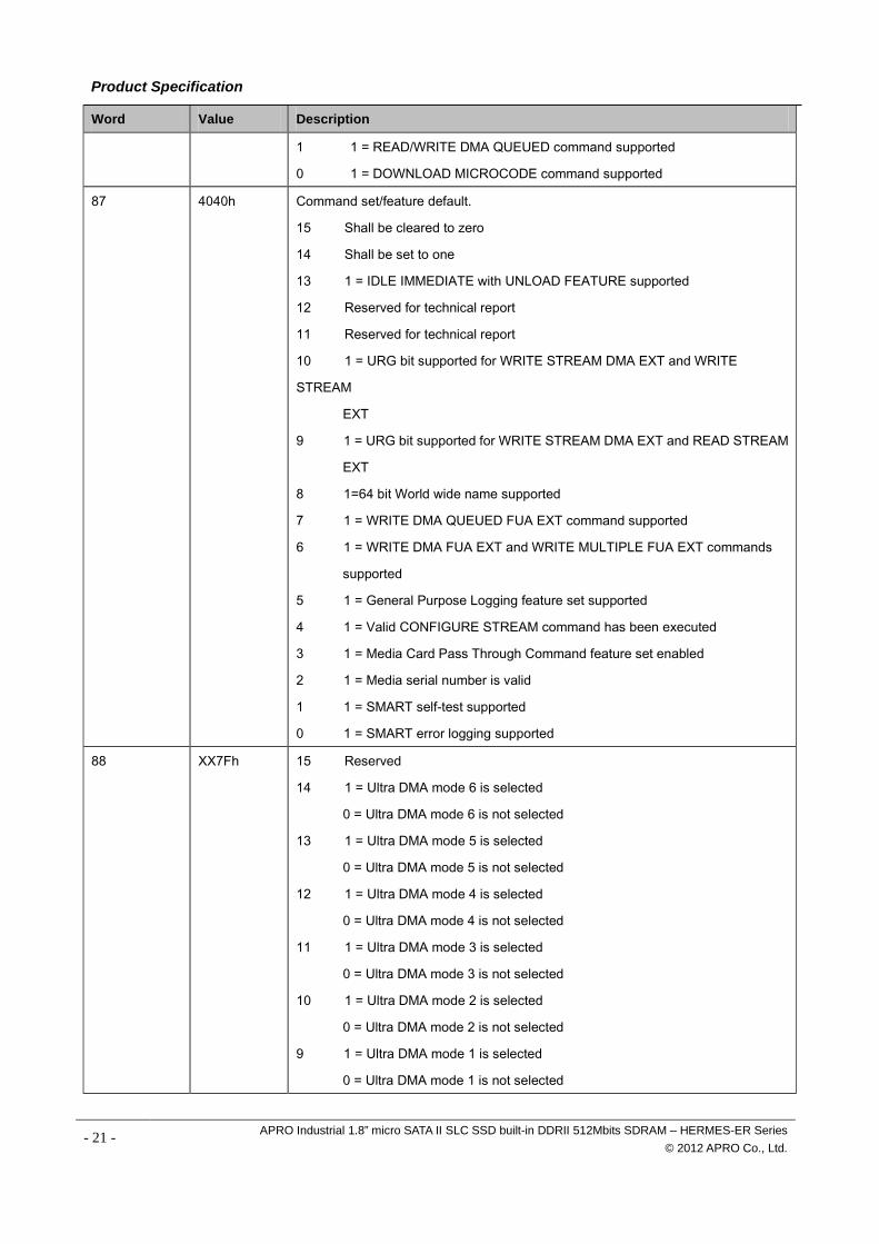
1 1 = READ/WRITE DMA QUEUED command supported
0 1 = DOWNLOAD MICROCODE command supported
87 4040h Command set/feature default.
15 Shall be cleared to zero
14 Shall be set to one
13 1 = IDLE IMMEDIATE with UNLOAD FEATURE supported
12 Reserved for technical report
11 Reserved for technical report
10 1 = URG bit supported for WRITE STREAM DMA EXT and WRITE
STREAM
EXT
9 1 = URG bit supported for WRITE STREAM DMA EXT and READ STREAM
EXT
8 1=64 bit World wide name supported
7 1 = WRITE DMA QUEUED FUA EXT command supported
6 1 = WRITE DMA FUA EXT and WRITE MULTIPLE FUA EXT commands
supported
5 1 = General Purpose Logging feature set supported
4 1 = Valid CONFIGURE STREAM command has been executed
3 1 = Media Card Pass Through Command feature set enabled
2 1 = Media serial number is valid
1 1 = SMART self-test supported
0 1 = SMART error logging supported
88 XX7Fh 15 Reserved
14 1 = Ultra DMA mode 6 is selected
0 = Ultra DMA mode 6 is not selected
13 1 = Ultra DMA mode 5 is selected
0 = Ultra DMA mode 5 is not selected
12 1 = Ultra DMA mode 4 is selected
0 = Ultra DMA mode 4 is not selected
11 1 = Ultra DMA mode 3 is selected
0 = Ultra DMA mode 3 is not selected
10 1 = Ultra DMA mode 2 is selected
0 = Ultra DMA mode 2 is not selected
9 1 = Ultra DMA mode 1 is selected
0 = Ultra DMA mode 1 is not selected
- 21 - APRO Industrial 1.8” micro SATA II SLC SSD built-in DDRII 512Mbits SDRAM – HERMES-ER Series © 2012 APRO Co., Ltd.
Product Specification
Word Value Description
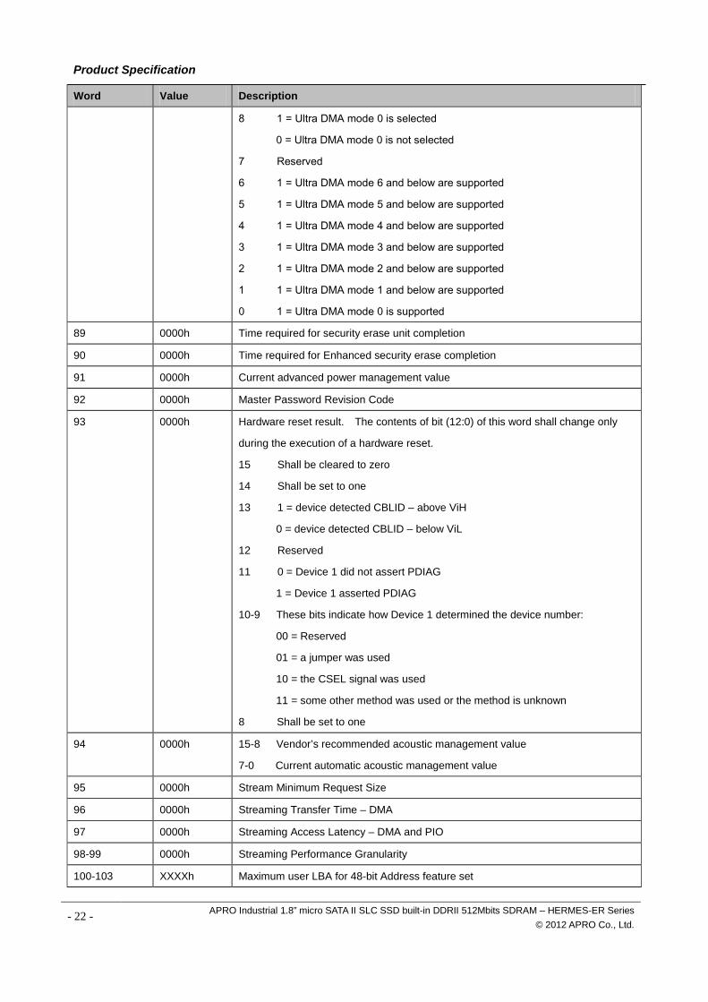
8 1 = Ultra DMA mode 0 is selected
0 = Ultra DMA mode 0 is not selected
7 Reserved
6 1 = Ultra DMA mode 6 and below are supported
5 1 = Ultra DMA mode 5 and below are supported
4 1 = Ultra DMA mode 4 and below are supported
3 1 = Ultra DMA mode 3 and below are supported
2 1 = Ultra DMA mode 2 and below are supported
1 1 = Ultra DMA mode 1 and below are supported
0 1 = Ultra DMA mode 0 is supported
89 0000h Time required for security erase unit completion
90 0000h Time required for Enhanced security erase completion
91 0000h Current advanced power management value
92 0000h Master Password Revision Code
93 0000h Hardware reset result. The contents of bit (12:0) of this word shall change only
during the execution of a hardware reset.
15 Shall be cleared to zero
14 Shall be set to one
13 1 = device detected CBLID – above ViH
0 = device detected CBLID – below ViL
12 Reserved
11 0 = Device 1 did not assert PDIAG
1 = Device 1 asserted PDIAG
10-9 These bits indicate how Device 1 determined the device number:
00 = Reserved
01 = a jumper was used
10 = the CSEL signal was used
11 = some other method was used or the method is unknown
8 Shall be set to one
94 0000h 15-8 Vendor’s recommended acoustic management value
7-0 Current automatic acoustic management value
95 0000h Stream Minimum Request Size
96 0000h Streaming Transfer Time – DMA
97 0000h Streaming Access Latency – DMA and PIO
98-99 0000h Streaming Performance Granularity
100-103 XXXXh Maximum user LBA for 48-bit Address feature set
- 22 - APRO Industrial 1.8” micro SATA II SLC SSD built-in DDRII 512Mbits SDRAM – HERMES-ER Series © 2012 APRO Co., Ltd.
Product Specification
Word Value Description
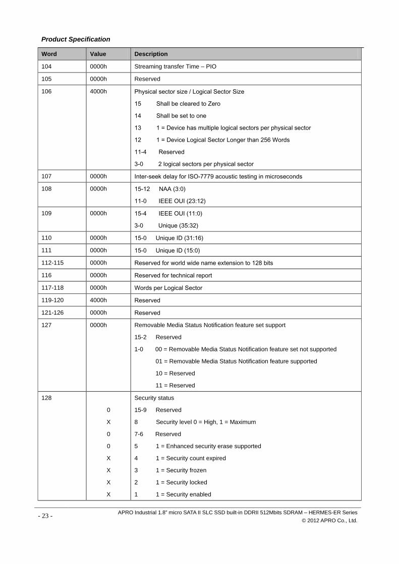
104 0000h Streaming transfer Time – PIO
105 0000h Reserved
106 4000h Physical sector size / Logical Sector Size
15 Shall be cleared to Zero
14 Shall be set to one
13 1 = Device has multiple logical sectors per physical sector
12 1 = Device Logical Sector Longer than 256 Words
11-4 Reserved
3-0 2 logical sectors per physical sector 107 0000h Inter-seek delay for ISO-7779 acoustic testing in microseconds
108 0000h 15-12 NAA (3:0)
11-0 IEEE OUI (23:12)
109 0000h 15-4 IEEE OUI (11:0)
3-0 Unique (35:32)
110 0000h 15-0 Unique ID (31:16)
111 0000h 15-0 Unique ID (15:0)
112-115 0000h Reserved for world wide name extension to 128 bits
116 0000h Reserved for technical report
117-118 0000h Words per Logical Sector
119-120 4000h Reserved
121-126 0000h Reserved
127 0000h Removable Media Status Notification feature set support
15-2 Reserved
1-0 00 = Removable Media Status Notification feature set not supported
01 = Removable Media Status Notification feature supported
10 = Reserved
11 = Reserved
128
0
X
0
0
X
X
X
X
Security status
15-9 Reserved
8 Security level 0 = High, 1 = Maximum
7-6 Reserved
5 1 = Enhanced security erase supported
4 1 = Security count expired
3 1 = Security frozen
2 1 = Security locked
1 1 = Security enabled
- 23 - APRO Industrial 1.8” micro SATA II SLC SSD built-in DDRII 512Mbits SDRAM – HERMES-ER Series © 2012 APRO Co., Ltd.
Product Specification
Word Value Description
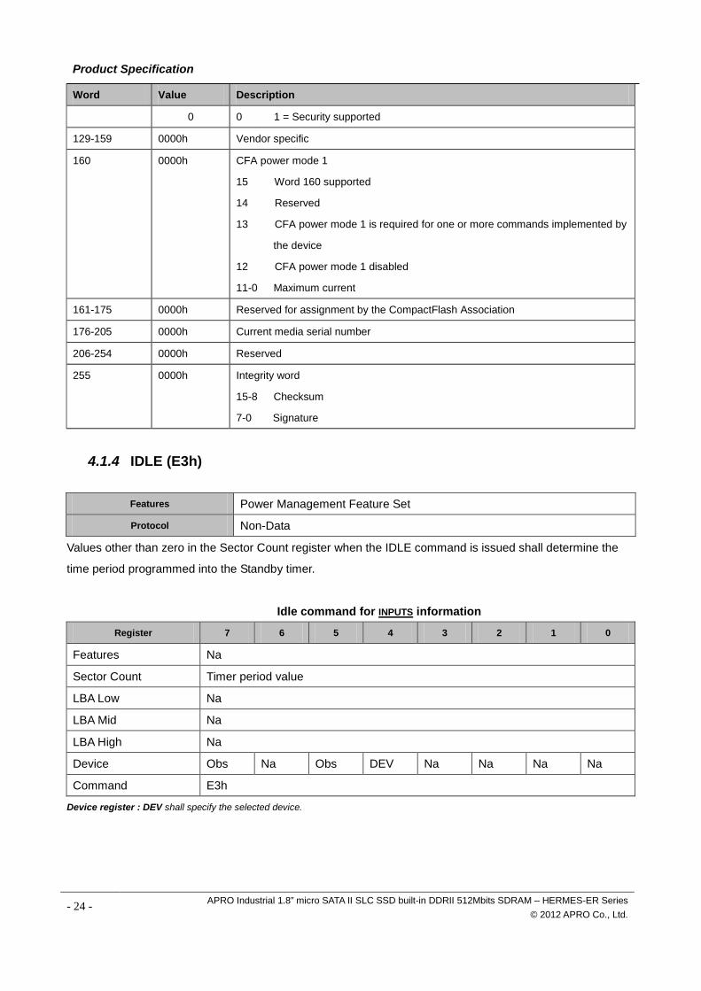
0 0 1 = Security supported
129-159 0000h Vendor specific
160 0000h CFA power mode 1
15 Word 160 supported
14 Reserved
13 CFA power mode 1 is required for one or more commands implemented by
the device
12 CFA power mode 1 disabled
11-0 Maximum current
161-175 0000h Reserved for assignment by the CompactFlash Association
176-205 0000h Current media serial number
206-254 0000h Reserved
255 0000h Integrity word
15-8 Checksum
7-0 Signature
4.1.4 IDLE (E3h) Features Power Management Feature Set
Protocol Non-Data
Values other than zero in the Sector Count register when the IDLE command is issued shall determine the
time period programmed into the Standby timer.
Idle command for INPUTS information
Register 7 6 5 4 3 2 1 0
Features Na
Sector Count Timer period value
LBA Low Na
LBA Mid Na
LBA High Na
Device Obs Na Obs DEV Na Na Na Na
Command E3h
Device register : DEV shall specify the selected device.
- 24 - APRO Industrial 1.8” micro SATA II SLC SSD built-in DDRII 512Mbits SDRAM – HERMES-ER Series © 2012 APRO Co., Ltd.
Product Specification
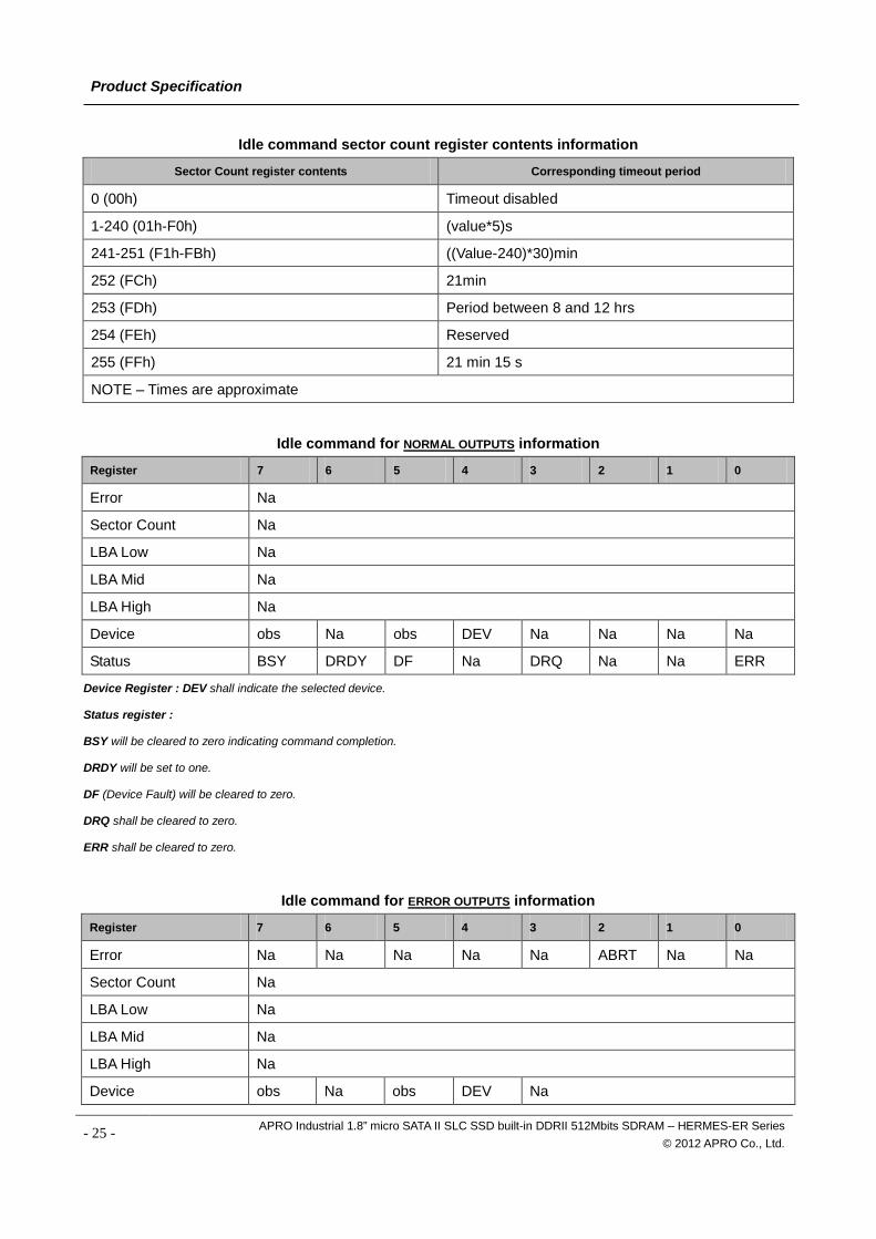
Idle command sector count register contents information
Sector Count register contents Corresponding timeout period
0 (00h) Timeout disabled
1-240 (01h-F0h) (value*5)s
241-251 (F1h-FBh) ((Value-240)*30)min
252 (FCh) 21min
253 (FDh) Period between 8 and 12 hrs
254 (FEh) Reserved
255 (FFh) 21 min 15 s
NOTE – Times are approximate
Idle command for NORMAL OUTPUTS information
Register 7 6 5 4 3 2 1 0
Error Na
Sector Count Na
LBA Low Na
LBA Mid Na
LBA High Na
Device obs Na obs DEV Na Na Na Na
Status BSY DRDY DF Na DRQ Na Na ERR
Device Register : DEV shall indicate the selected device.
Status register :
BSY will be cleared to zero indicating command completion.
DRDY will be set to one.
DF (Device Fault) will be cleared to zero.
DRQ shall be cleared to zero.
ERR shall be cleared to zero.
Idle command for ERROR OUTPUTS information
Register 7 6 5 4 3 2 1 0
Error Na Na Na Na Na ABRT Na Na
Sector Count Na
LBA Low Na
LBA Mid Na
LBA High Na
Device obs Na obs DEV Na
- 25 - APRO Industrial 1.8” micro SATA II SLC SSD built-in DDRII 512Mbits SDRAM – HERMES-ER Series © 2012 APRO Co., Ltd.
Product Specification
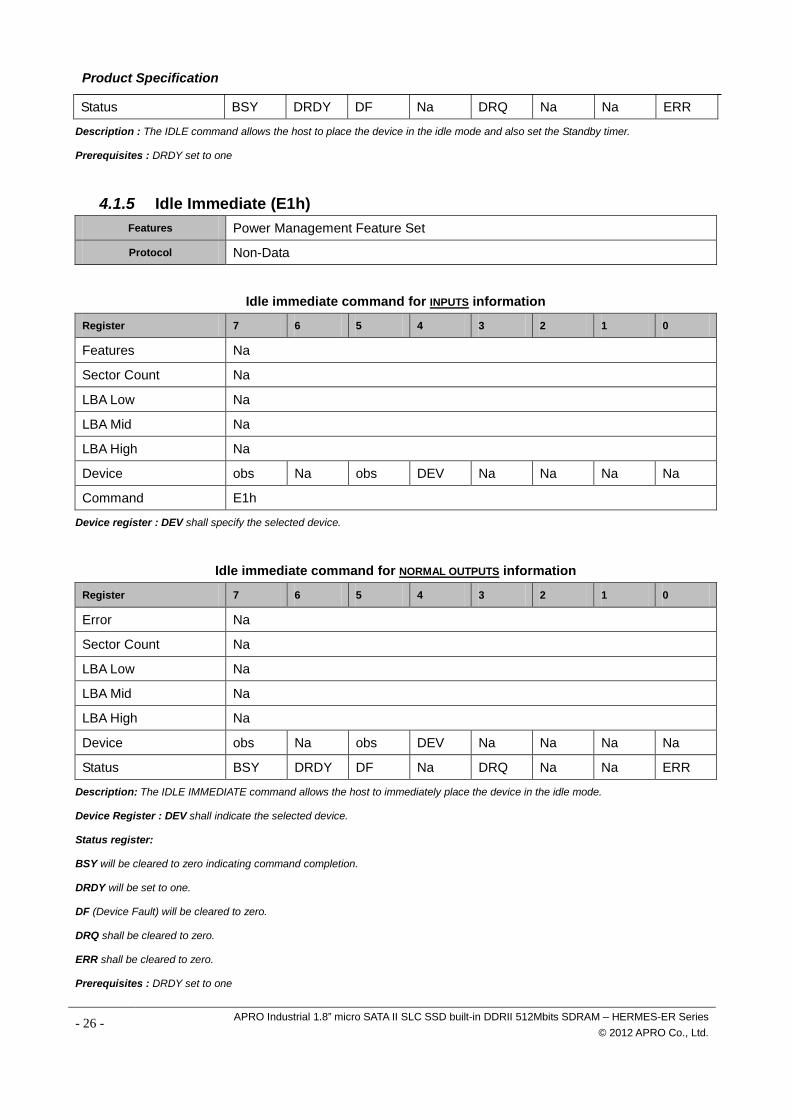
Status BSY DRDY DF Na DRQ Na Na ERR
Description : The IDLE command allows the host to place the device in the idle mode and also set the Standby timer.
Prerequisites : DRDY set to one
4.1.5 Idle Immediate (E1h)
Features Power Management Feature Set
Protocol Non-Data
Idle immediate command for INPUTS information
Register 7 6 5 4 3 2 1 0
Features Na
Sector Count Na
LBA Low Na
LBA Mid Na
LBA High Na
Device obs Na obs DEV Na Na Na Na
Command E1h
Device register : DEV shall specify the selected device.
Idle immediate command for NORMAL OUTPUTS information
Register 7 6 5 4 3 2 1 0
Error Na
Sector Count Na
LBA Low Na
LBA Mid Na
LBA High Na
Device obs Na obs DEV Na Na Na Na
Status BSY DRDY DF Na DRQ Na Na ERR
Description: The IDLE IMMEDIATE command allows the host to immediately place the device in the idle mode.
Device Register : DEV shall indicate the selected device.
Status register:
BSY will be cleared to zero indicating command completion.
DRDY will be set to one.
DF (Device Fault) will be cleared to zero.
DRQ shall be cleared to zero.
ERR shall be cleared to zero.
Prerequisites : DRDY set to one
- 26 - APRO Industrial 1.8” micro SATA II SLC SSD built-in DDRII 512Mbits SDRAM – HERMES-ER Series © 2012 APRO Co., Ltd.
Product Specification
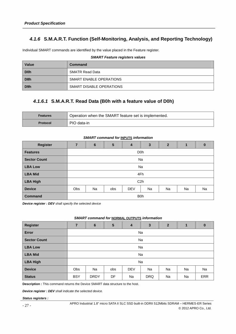
4.1.6 S.M.A.R.T. Function (Self-Monitoring, Analysis, and Reporting Technology)
Individual SMART commands are identified by the value placed in the Feature register.
SMART Feature registers values
Value Command
D0h SMATR Read Data
D8h SMART ENABLE OPERATIONS
D9h SMART DISABLE OPERATIONS
4.1.6.1 S.M.A.R.T. Read Data (B0h with a feature value of D0h)
Features Operation when the SMART feature set is implemented.
Protocol PIO data-in
SMART command for INPUTS information
Register 7 6 5 4 3 2 1 0
Features D0h
Sector Count Na
LBA Low Na
LBA Mid 4Fh
LBA High C2h
Device Obs Na obs DEV Na Na Na Na
Command B0h
Device register : DEV shall specify the selected device
SMART command for NORMAL OUTPUTS information
Register 7 6 5 4 3 2 1 0
Error Na
Sector Count Na
LBA Low Na
LBA Mid Na
LBA High Na
Device Obs Na obs DEV Na Na Na Na
Status BSY DRDY DF Na DRQ Na Na ERR
Description : This command returns the Device SMART data structure to the host.
Device register : DEV shall indicate the selected device.
Status registers :
- 27 - APRO Industrial 1.8” micro SATA II SLC SSD built-in DDRII 512Mbits SDRAM – HERMES-ER Series © 2012 APRO Co., Ltd.
Product Specification
BSY will be cleared to zero indicating command completion.
DRDY will be set to one. SMART enabled.
DF (Device Fault) will be cleared to zero.
DRQ shall be cleared to zero.
ERR shall be cleared to zero.
Prerequisites : DRDY set to one. SMART enabled.
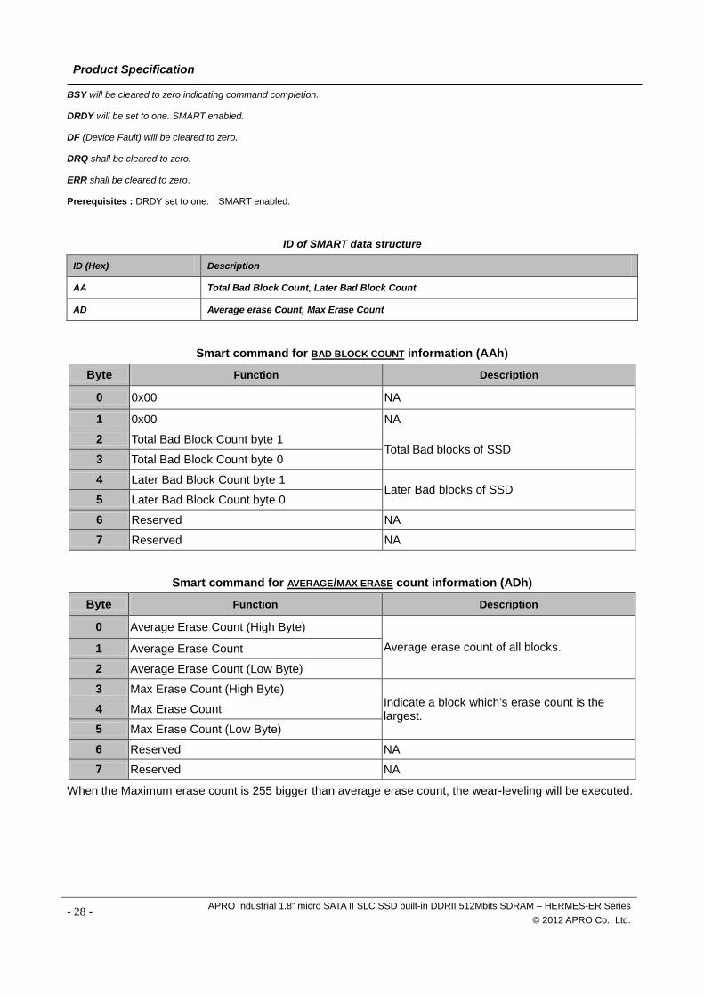
ID of SMART data structure
ID (Hex) Description
AA Total Bad Block Count, Later Bad Block Count
AD Average erase Count, Max Erase Count
Smart command for BAD BLOCK COUNT information (AAh)
Byte Function Description
0 0x00 NA
1 0x00 NA
2 Total Bad Block Count byte 1 Total Bad blocks of SSD
3 Total Bad Block Count byte 0
4 Later Bad Block Count byte 1 Later Bad blocks of SSD
5 Later Bad Block Count byte 0
6 Reserved NA
7 Reserved NA
Smart command for AVERAGE/MAX ERASE count information (ADh)
Byte Function Description
0 Average Erase Count (High Byte)
Average erase count of all blocks. 1 Average Erase Count
2 Average Erase Count (Low Byte)
3 Max Erase Count (High Byte) Indicate a block which’s erase count is the largest. 4 Max Erase Count
5 Max Erase Count (Low Byte)
6 Reserved NA
7 Reserved NA
When the Maximum erase count is 255 bigger than average erase count, the wear-leveling will be executed.
- 28 - APRO Industrial 1.8” micro SATA II SLC SSD built-in DDRII 512Mbits SDRAM – HERMES-ER Series © 2012 APRO Co., Ltd.
Product Specification
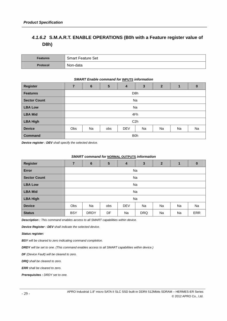
4.1.6.2 S.M.A.R.T. ENABLE OPERATIONS (B0h with a Feature register value of D8h)
Features Smart Feature Set
Protocol Non-data
SMART Enable command for INPUTS information
Register 7 6 5 4 3 2 1 0
Features D8h
Sector Count Na
LBA Low Na
LBA Mid 4Fh
LBA High C2h
Device Obs Na obs DEV Na Na Na Na
Command B0h
Device register : DEV shall specify the selected device.
SMART command for NORMAL OUTPUTS information
Register 7 6 5 4 3 2 1 0
Error Na
Sector Count Na
LBA Low Na
LBA Mid Na
LBA High Na
Device Obs Na obs DEV Na Na Na Na
Status BSY DRDY DF Na DRQ Na Na ERR
Description : This command enables access to all SMART capabilities within device.
Device Register : DEV shall indicate the selected device.
Status register:
BSY will be cleared to zero indicating command completion.
DRDY will be set to one. (This command enables access to all SMART capabilities within device.)
DF (Device Fault) will be cleared to zero.
DRQ shall be cleared to zero.
ERR shall be cleared to zero.
Prerequisites : DRDY set to one.
- 29 - APRO Industrial 1.8” micro SATA II SLC SSD built-in DDRII 512Mbits SDRAM – HERMES-ER Series © 2012 APRO Co., Ltd.
Product Specification
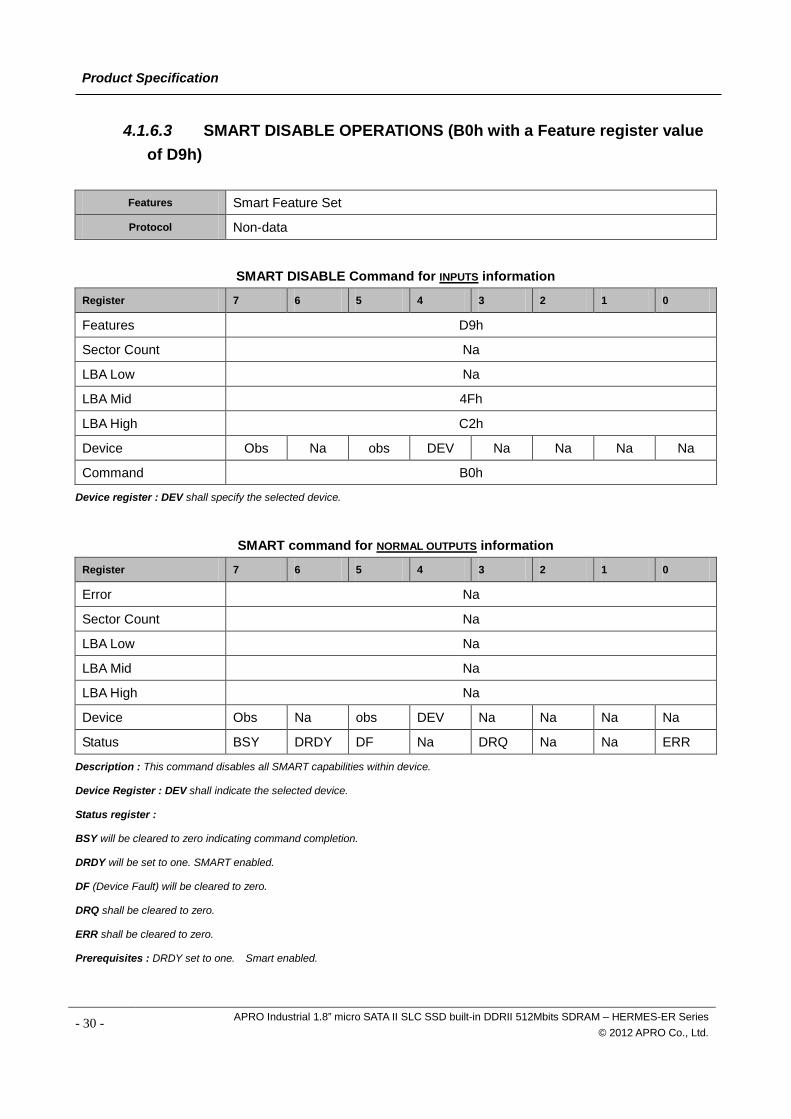
4.1.6.3 SMART DISABLE OPERATIONS (B0h with a Feature register value of D9h)
Features Smart Feature Set
Protocol Non-data
SMART DISABLE Command for INPUTS information
Register 7 6 5 4 3 2 1 0
Features D9h
Sector Count Na
LBA Low Na
LBA Mid 4Fh
LBA High C2h
Device Obs Na obs DEV Na Na Na Na
Command B0h
Device register : DEV shall specify the selected device.
SMART command for NORMAL OUTPUTS information
Register 7 6 5 4 3 2 1 0
Error Na
Sector Count Na
LBA Low Na
LBA Mid Na
LBA High Na
Device Obs Na obs DEV Na Na Na Na
Status BSY DRDY DF Na DRQ Na Na ERR
Description : This command disables all SMART capabilities within device.
Device Register : DEV shall indicate the selected device.
Status register :
BSY will be cleared to zero indicating command completion.
DRDY will be set to one. SMART enabled.
DF (Device Fault) will be cleared to zero.
DRQ shall be cleared to zero.
ERR shall be cleared to zero.
Prerequisites : DRDY set to one. Smart enabled.
- 30 - APRO Industrial 1.8” micro SATA II SLC SSD built-in DDRII 512Mbits SDRAM – HERMES-ER Series © 2012 APRO Co., Ltd.
Product Specification
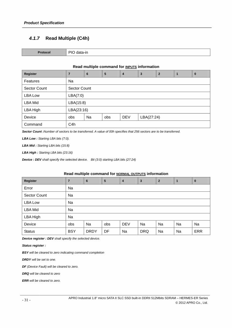
4.1.7 Read Multiple (C4h)
Protocol PIO data-in
Read multiple command for INPUTS information
Register 7 6 5 4 3 2 1 0
Features Na
Sector Count Sector Count
LBA Low LBA(7:0)
LBA Mid LBA(15:8)
LBA High LBA(23:16)
Device obs Na obs DEV LBA(27:24)
Command C4h
Sector Count :Number of sectors to be transferred. A value of 00h specifies that 256 sectors are to be transferred.
LBA Low : Starting LBA bits (7:0).
LBA Mid : Starting LBA bits (15:8)
LBA High : Starting LBA bits (23:16)
Device : DEV shall specify the selected device. Bit (3:0) starting LBA bits (27:24)
Read multiple command for NORMAL OUTPUTS information
Register 7 6 5 4 3 2 1 0
Error Na
Sector Count Na
LBA Low Na
LBA Mid Na
LBA High Na
Device obs Na obs DEV Na Na Na Na
Status BSY DRDY DF Na DRQ Na Na ERR
Device register : DEV shall specify the selected device.
Status register :
BSY will be cleared to zero indicating command completion
DRDY will be set to one.
DF (Device Fault) will be cleared to zero.
DRQ will be cleared to zero
ERR will be cleared to zero.
- 31 - APRO Industrial 1.8” micro SATA II SLC SSD built-in DDRII 512Mbits SDRAM – HERMES-ER Series © 2012 APRO Co., Ltd.
Product Specification
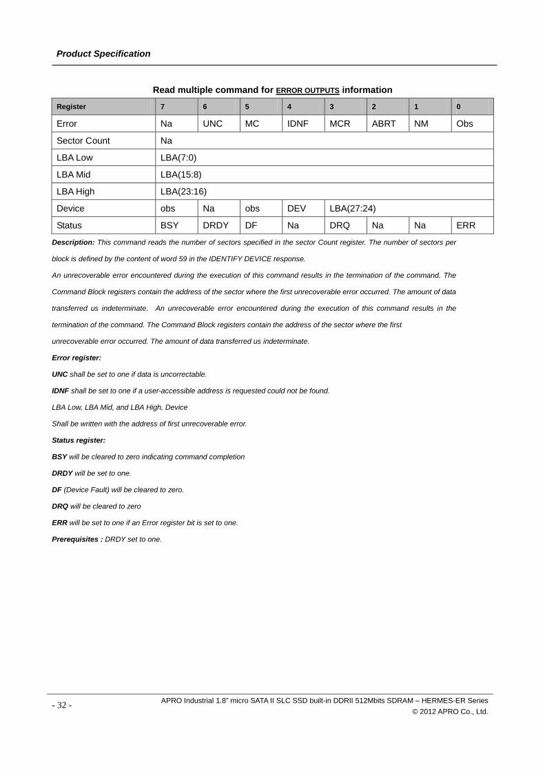
Read multiple command for ERROR OUTPUTS information
Register 7 6 5 4 3 2 1 0
Error Na UNC MC IDNF MCR ABRT NM Obs
Sector Count Na
LBA Low LBA(7:0)
LBA Mid LBA(15:8)
LBA High LBA(23:16)
Device obs Na obs DEV LBA(27:24)
Status BSY DRDY DF Na DRQ Na Na ERR
Description: This command reads the number of sectors specified in the sector Count register. The number of sectors per
block is defined by the content of word 59 in the IDENTIFY DEVICE response.
An unrecoverable error encountered during the execution of this command results in the termination of the command. The
Command Block registers contain the address of the sector where the first unrecoverable error occurred. The amount of data
transferred us indeterminate. An unrecoverable error encountered during the execution of this command results in the
termination of the command. The Command Block registers contain the address of the sector where the first
unrecoverable error occurred. The amount of data transferred us indeterminate.
Error register:
UNC shall be set to one if data is uncorrectable.
IDNF shall be set to one if a user-accessible address is requested could not be found.
LBA Low, LBA Mid, and LBA High, Device
Shall be written with the address of first unrecoverable error.
Status register:
BSY will be cleared to zero indicating command completion
DRDY will be set to one.
DF (Device Fault) will be cleared to zero.
DRQ will be cleared to zero
ERR will be set to one if an Error register bit is set to one.
Prerequisites : DRDY set to one.
- 32 - APRO Industrial 1.8” micro SATA II SLC SSD built-in DDRII 512Mbits SDRAM – HERMES-ER Series © 2012 APRO Co., Ltd.
Product Specification
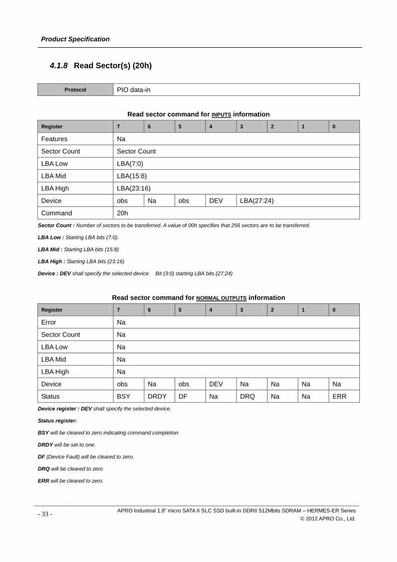
4.1.8 Read Sector(s) (20h)
Protocol PIO data-in
Read sector command for INPUTS information
Register 7 6 5 4 3 2 1 0
Features Na
Sector Count Sector Count
LBA Low LBA(7:0)
LBA Mid LBA(15:8)
LBA High LBA(23:16)
Device obs Na obs DEV LBA(27:24)
Command 20h
Sector Count : Number of sectors to be transferred. A value of 00h specifies that 256 sectors are to be transferred.
LBA Low : Starting LBA bits (7:0).
LBA Mid : Starting LBA bits (15:8)
LBA High : Starting LBA bits (23:16)
Device : DEV shall specify the selected device. Bit (3:0) starting LBA bits (27:24)
Read sector command for NORMAL OUTPUTS information
Register 7 6 5 4 3 2 1 0
Error Na
Sector Count Na
LBA Low Na
LBA Mid Na
LBA High Na
Device obs Na obs DEV Na Na Na Na
Status BSY DRDY DF Na DRQ Na Na ERR
Device register : DEV shall specify the selected device.
Status register:
BSY will be cleared to zero indicating command completion
DRDY will be set to one.
DF (Device Fault) will be cleared to zero.
DRQ will be cleared to zero
ERR will be cleared to zero.
- 33 - APRO Industrial 1.8” micro SATA II SLC SSD built-in DDRII 512Mbits SDRAM – HERMES-ER Series © 2012 APRO Co., Ltd.
Product Specification
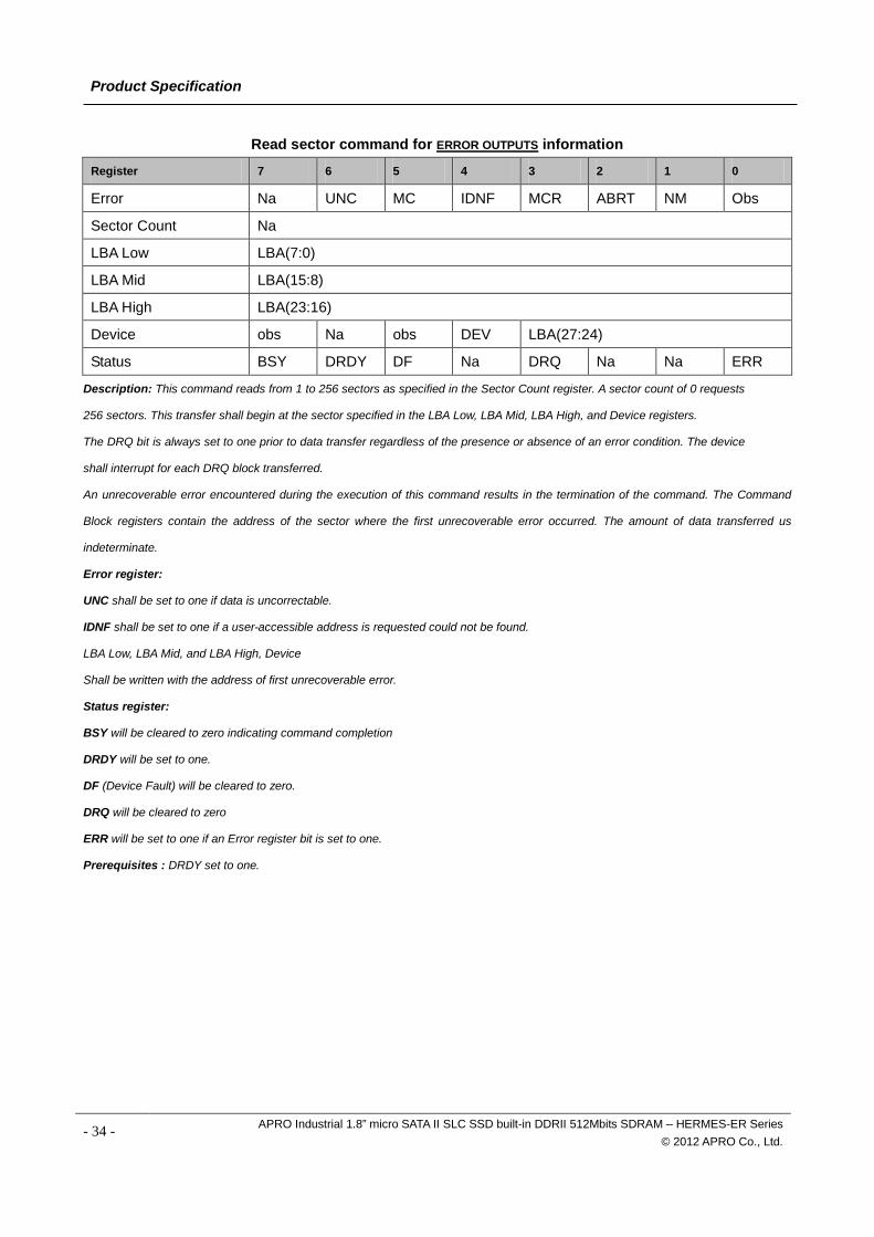
Read sector command for ERROR OUTPUTS information
Register 7 6 5 4 3 2 1 0
Error Na UNC MC IDNF MCR ABRT NM Obs
Sector Count Na
LBA Low LBA(7:0)
LBA Mid LBA(15:8)
LBA High LBA(23:16)
Device obs Na obs DEV LBA(27:24)
Status BSY DRDY DF Na DRQ Na Na ERR
Description: This command reads from 1 to 256 sectors as specified in the Sector Count register. A sector count of 0 requests
256 sectors. This transfer shall begin at the sector specified in the LBA Low, LBA Mid, LBA High, and Device registers.
The DRQ bit is always set to one prior to data transfer regardless of the presence or absence of an error condition. The device
shall interrupt for each DRQ block transferred.
An unrecoverable error encountered during the execution of this command results in the termination of the command. The Command
Block registers contain the address of the sector where the first unrecoverable error occurred. The amount of data transferred us
indeterminate.
Error register:
UNC shall be set to one if data is uncorrectable.
IDNF shall be set to one if a user-accessible address is requested could not be found.
LBA Low, LBA Mid, and LBA High, Device
Shall be written with the address of first unrecoverable error.
Status register:
BSY will be cleared to zero indicating command completion
DRDY will be set to one.
DF (Device Fault) will be cleared to zero.
DRQ will be cleared to zero
ERR will be set to one if an Error register bit is set to one.
Prerequisites : DRDY set to one.
- 34 - APRO Industrial 1.8” micro SATA II SLC SSD built-in DDRII 512Mbits SDRAM – HERMES-ER Series © 2012 APRO Co., Ltd.
Product Specification
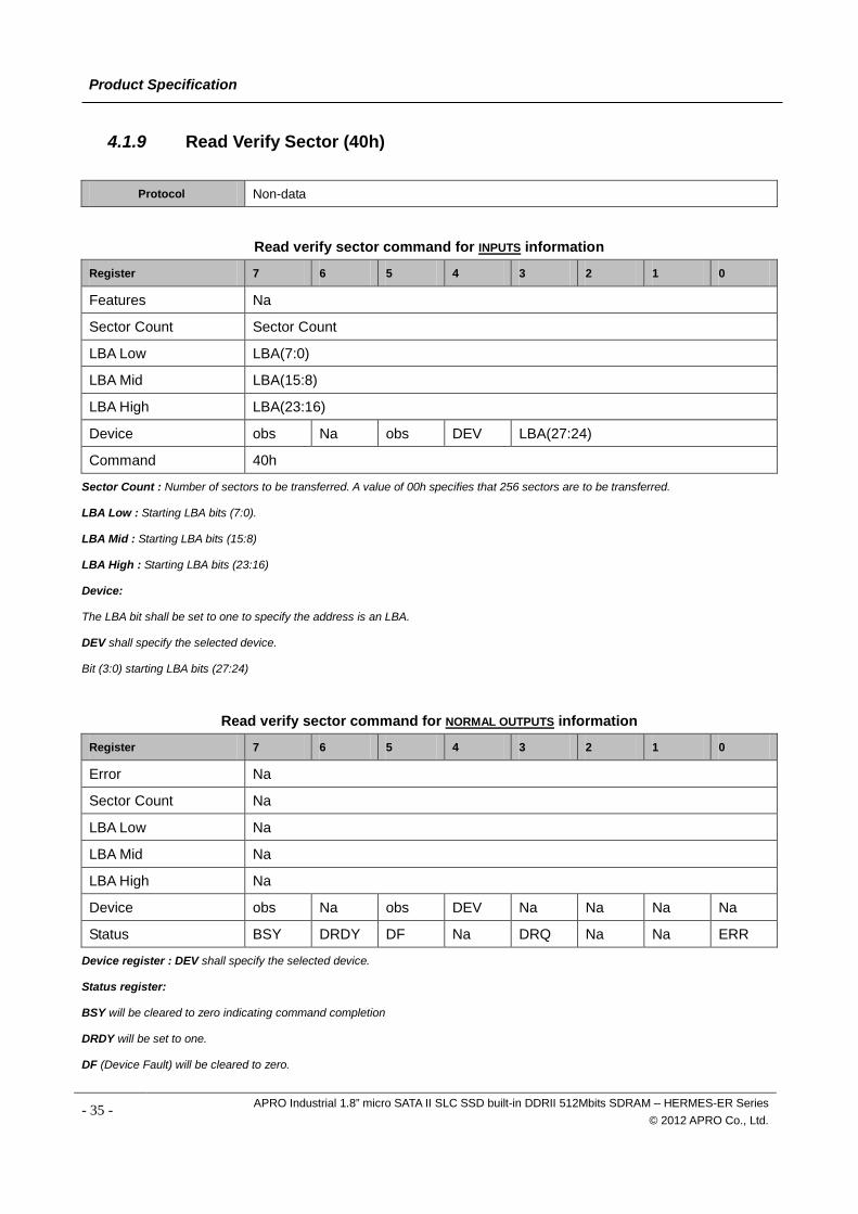
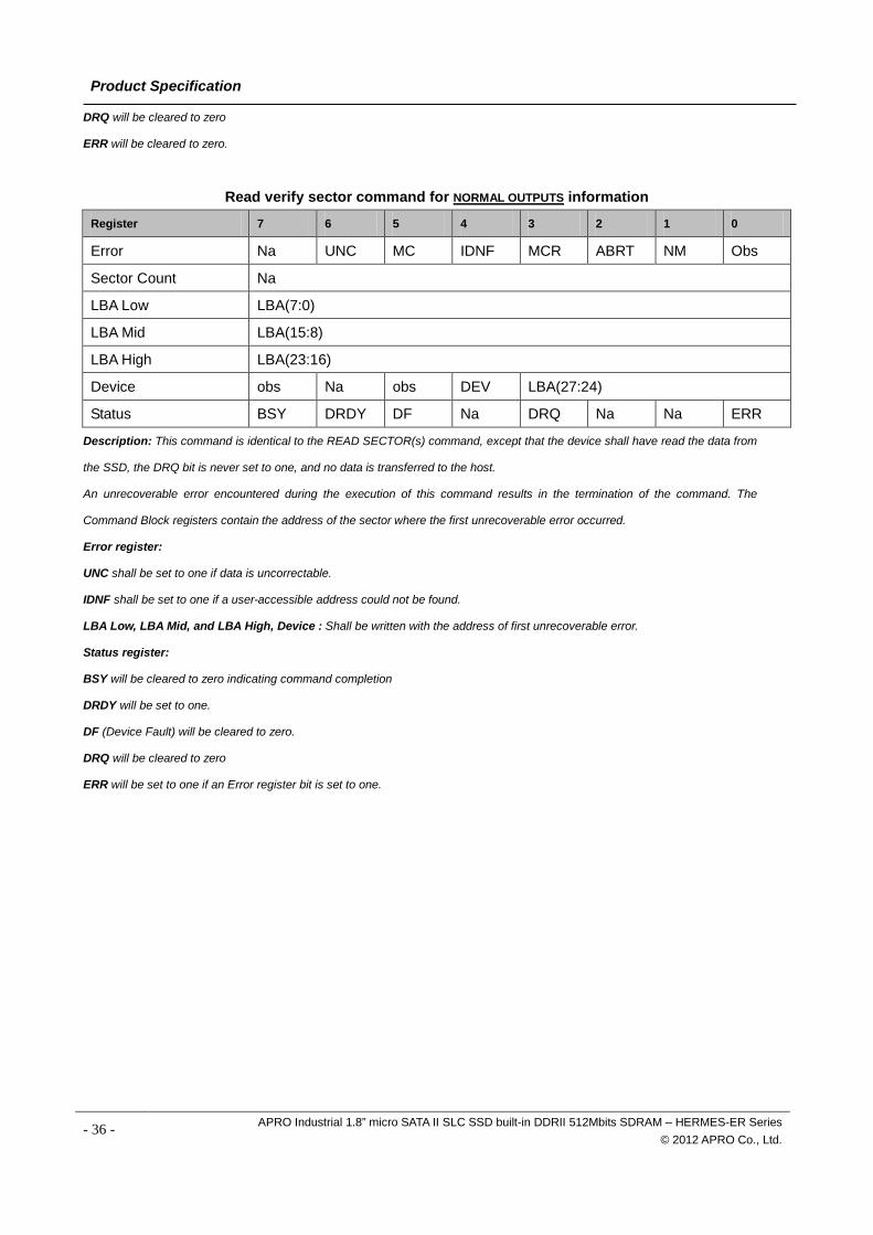
4.1.9 Read Verify Sector (40h)
Protocol Non-data
Read verify sector command for INPUTS information
Register 7 6 5 4 3 2 1 0
Features Na
Sector Count Sector Count
LBA Low LBA(7:0)
LBA Mid LBA(15:8)
LBA High LBA(23:16)
Device obs Na obs DEV LBA(27:24)
Command 40h
Sector Count : Number of sectors to be transferred. A value of 00h specifies that 256 sectors are to be transferred.
LBA Low : Starting LBA bits (7:0).
LBA Mid : Starting LBA bits (15:8)
LBA High : Starting LBA bits (23:16)
Device:
The LBA bit shall be set to one to specify the address is an LBA.
DEV shall specify the selected device.
Bit (3:0) starting LBA bits (27:24)
Read verify sector command for NORMAL OUTPUTS information
Register 7 6 5 4 3 2 1 0
Error Na
Sector Count Na
LBA Low Na
LBA Mid Na
LBA High Na
Device obs Na obs DEV Na Na Na Na
Status BSY DRDY DF Na DRQ Na Na ERR
Device register : DEV shall specify the selected device.
Status register:
BSY will be cleared to zero indicating command completion
DRDY will be set to one.
DF (Device Fault) will be cleared to zero.
- 35 - APRO Industrial 1.8” micro SATA II SLC SSD built-in DDRII 512Mbits SDRAM – HERMES-ER Series © 2012 APRO Co., Ltd.
Product Specification
DRQ will be cleared to zero
ERR will be cleared to zero.
Read verify sector command for NORMAL OUTPUTS information
Register 7 6 5 4 3 2 1 0
Error Na UNC MC IDNF MCR ABRT NM Obs
Sector Count Na
LBA Low LBA(7:0)
LBA Mid LBA(15:8)
LBA High LBA(23:16)
Device obs Na obs DEV LBA(27:24)
Status BSY DRDY DF Na DRQ Na Na ERR
Description: This command is identical to the READ SECTOR(s) command, except that the device shall have read the data from
the SSD, the DRQ bit is never set to one, and no data is transferred to the host.
An unrecoverable error encountered during the execution of this command results in the termination of the command. The
Command Block registers contain the address of the sector where the first unrecoverable error occurred.
Error register:
UNC shall be set to one if data is uncorrectable.
IDNF shall be set to one if a user-accessible address could not be found.
LBA Low, LBA Mid, and LBA High, Device : Shall be written with the address of first unrecoverable error.
Status register:
BSY will be cleared to zero indicating command completion
DRDY will be set to one.
DF (Device Fault) will be cleared to zero.
DRQ will be cleared to zero
ERR will be set to one if an Error register bit is set to one.
- 36 - APRO Industrial 1.8” micro SATA II SLC SSD built-in DDRII 512Mbits SDRAM – HERMES-ER Series © 2012 APRO Co., Ltd.
Product Specification
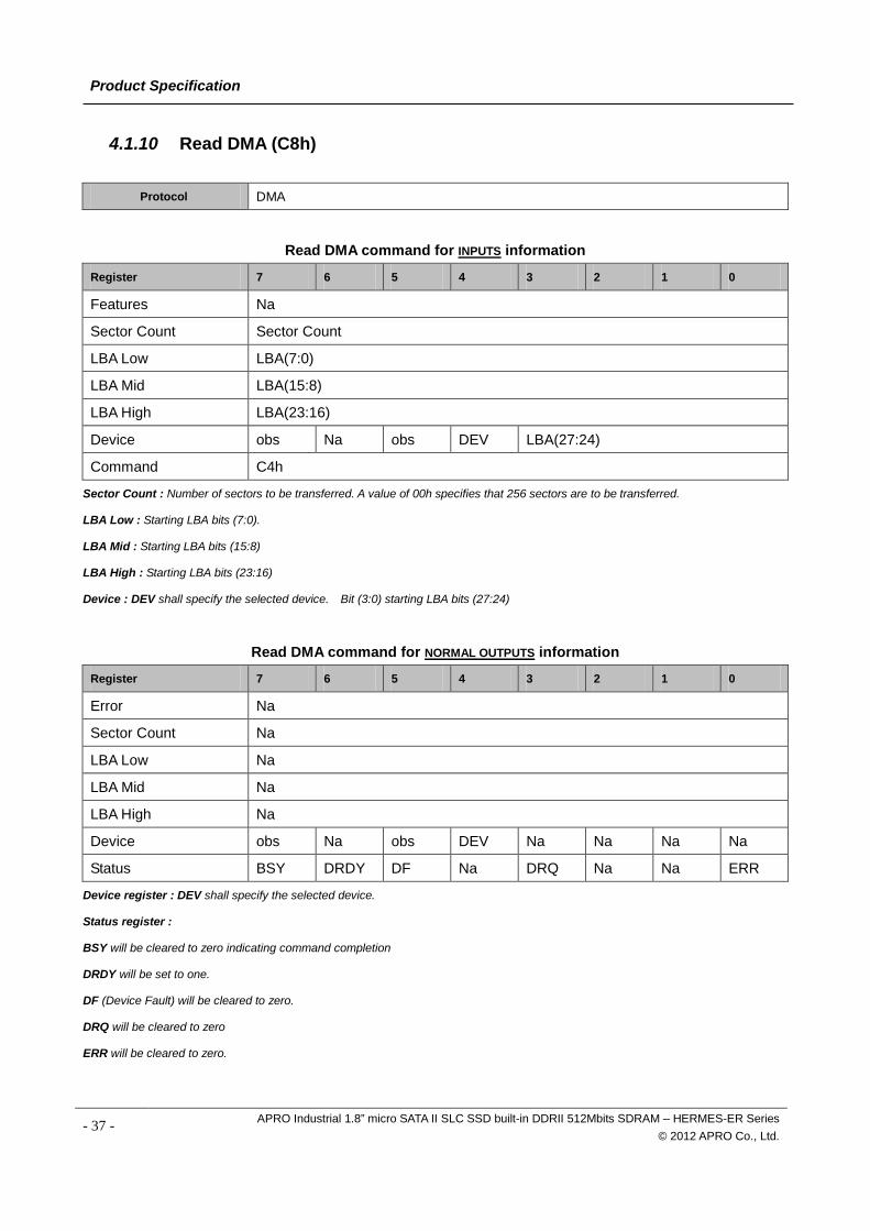
4.1.10 Read DMA (C8h)
Protocol DMA
Read DMA command for INPUTS information
Register 7 6 5 4 3 2 1 0
Features Na
Sector Count Sector Count
LBA Low LBA(7:0)
LBA Mid LBA(15:8)
LBA High LBA(23:16)
Device obs Na obs DEV LBA(27:24)
Command C4h
Sector Count : Number of sectors to be transferred. A value of 00h specifies that 256 sectors are to be transferred.
LBA Low : Starting LBA bits (7:0).
LBA Mid : Starting LBA bits (15:8)
LBA High : Starting LBA bits (23:16)
Device : DEV shall specify the selected device. Bit (3:0) starting LBA bits (27:24)
Read DMA command for NORMAL OUTPUTS information
Register 7 6 5 4 3 2 1 0
Error Na
Sector Count Na
LBA Low Na
LBA Mid Na
LBA High Na
Device obs Na obs DEV Na Na Na Na
Status BSY DRDY DF Na DRQ Na Na ERR
Device register : DEV shall specify the selected device.
Status register :
BSY will be cleared to zero indicating command completion
DRDY will be set to one.
DF (Device Fault) will be cleared to zero.
DRQ will be cleared to zero
ERR will be cleared to zero.
- 37 - APRO Industrial 1.8” micro SATA II SLC SSD built-in DDRII 512Mbits SDRAM – HERMES-ER Series © 2012 APRO Co., Ltd.
Product Specification
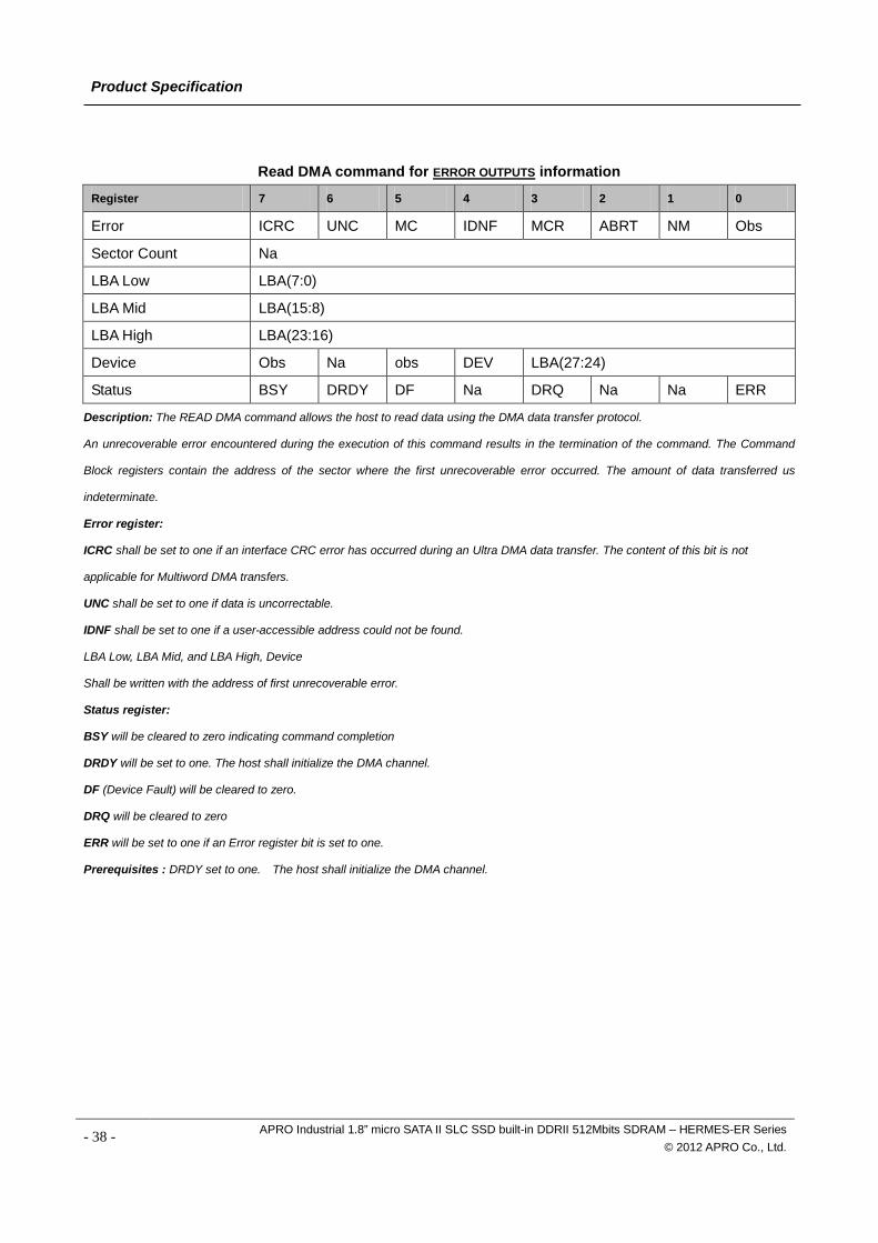
Read DMA command for ERROR OUTPUTS information
Register 7 6 5 4 3 2 1 0
Error ICRC UNC MC IDNF MCR ABRT NM Obs
Sector Count Na
LBA Low LBA(7:0)
LBA Mid LBA(15:8)
LBA High LBA(23:16)
Device Obs Na obs DEV LBA(27:24)
Status BSY DRDY DF Na DRQ Na Na ERR
Description: The READ DMA command allows the host to read data using the DMA data transfer protocol.
An unrecoverable error encountered during the execution of this command results in the termination of the command. The Command
Block registers contain the address of the sector where the first unrecoverable error occurred. The amount of data transferred us
indeterminate.
Error register:
ICRC shall be set to one if an interface CRC error has occurred during an Ultra DMA data transfer. The content of this bit is not
applicable for Multiword DMA transfers.
UNC shall be set to one if data is uncorrectable.
IDNF shall be set to one if a user-accessible address could not be found.
LBA Low, LBA Mid, and LBA High, Device
Shall be written with the address of first unrecoverable error.
Status register:
BSY will be cleared to zero indicating command completion
DRDY will be set to one. The host shall initialize the DMA channel.
DF (Device Fault) will be cleared to zero.
DRQ will be cleared to zero
ERR will be set to one if an Error register bit is set to one.
Prerequisites : DRDY set to one. The host shall initialize the DMA channel.
- 38 - APRO Industrial 1.8” micro SATA II SLC SSD built-in DDRII 512Mbits SDRAM – HERMES-ER Series © 2012 APRO Co., Ltd.
Product Specification
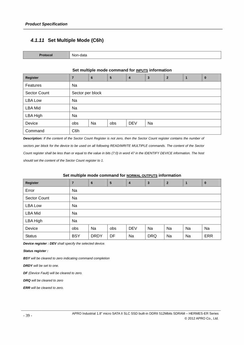
4.1.11 Set Multiple Mode (C6h)
Protocol Non-data
Set multiple mode command for INPUTS information
Register 7 6 5 4 3 2 1 0
Features Na
Sector Count Sector per block
LBA Low Na
LBA Mid Na
LBA High Na
Device obs Na obs DEV Na
Command C6h
Description: If the content of the Sector Count Register is not zero, then the Sector Count register contains the number of
sectors per block for the device to be used on all following READ/WRITE MULTIPLE commands. The content of the Sector
Count register shall be less than or equal to the value in bits (7:0) in word 47 in the IDENTIFY DEVICE information. The host
should set the content of the Sector Count register to 1.
Set multiple mode command for NORMAL OUTPUTS information
Register 7 6 5 4 3 2 1 0
Error Na
Sector Count Na
LBA Low Na
LBA Mid Na
LBA High Na
Device obs Na obs DEV Na Na Na Na
Status BSY DRDY DF Na DRQ Na Na ERR
Device register : DEV shall specify the selected device.
Status register :
BSY will be cleared to zero indicating command completion
DRDY will be set to one.
DF (Device Fault) will be cleared to zero.
DRQ will be cleared to zero
ERR will be cleared to zero.
- 39 - APRO Industrial 1.8” micro SATA II SLC SSD built-in DDRII 512Mbits SDRAM – HERMES-ER Series © 2012 APRO Co., Ltd.
Product Specification
Set multiple mode command for ERROR OUTPUTS information
Register 7 6 5 4 3 2 1 0
Error Na Na obs Na Na ABRT Na Na
Sector Count Na
LBA Low Na
LBA Mid Na
LBA High Na
Device Obs Na obs DEV Na
Status BSY DRDY DF Na DRQ Na Na ERR
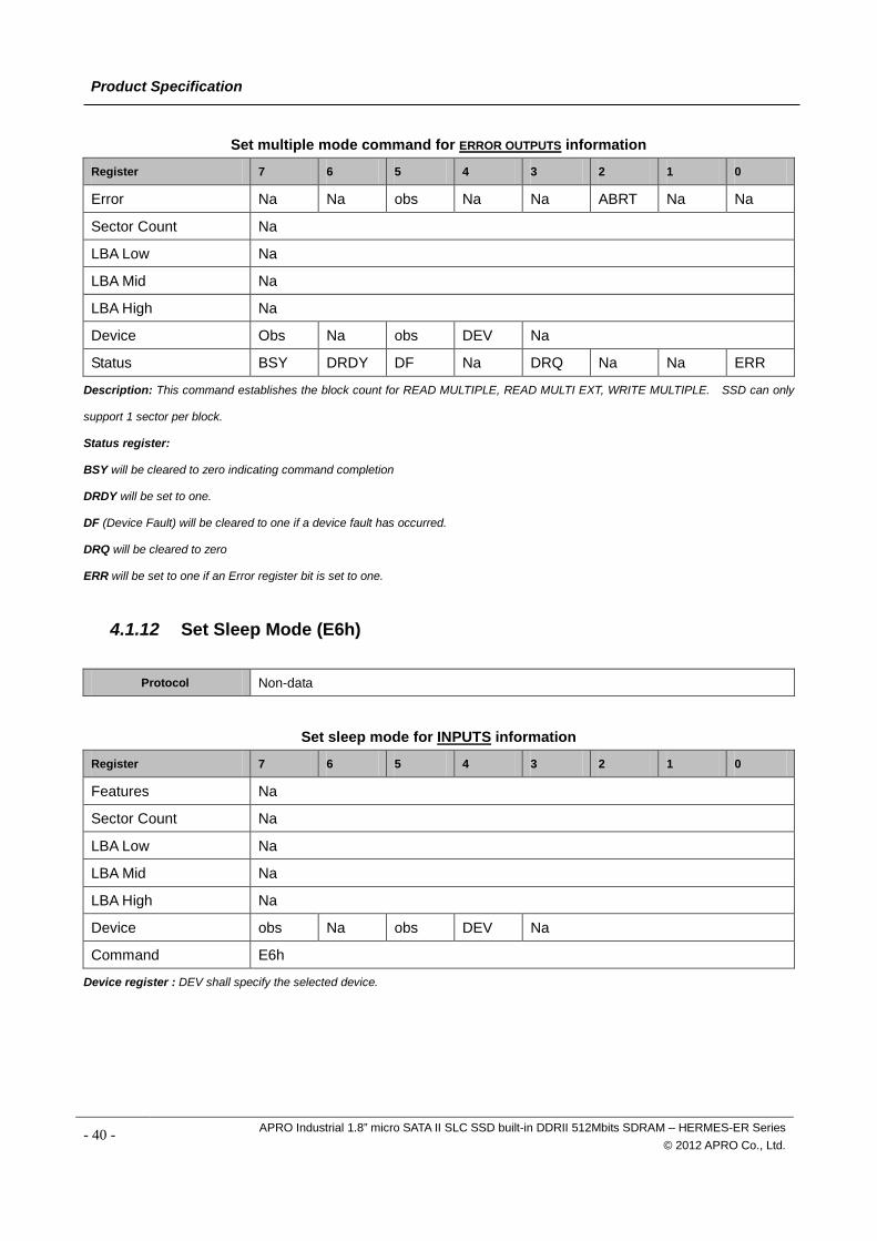
Description: This command establishes the block count for READ MULTIPLE, READ MULTI EXT, WRITE MULTIPLE. SSD can only
support 1 sector per block.
Status register:
BSY will be cleared to zero indicating command completion
DRDY will be set to one.
DF (Device Fault) will be cleared to one if a device fault has occurred.
DRQ will be cleared to zero
ERR will be set to one if an Error register bit is set to one.
4.1.12 Set Sleep Mode (E6h)
Protocol Non-data
Set sleep mode for INPUTS information
Register 7 6 5 4 3 2 1 0
Features Na
Sector Count Na
LBA Low Na
LBA Mid Na
LBA High Na
Device obs Na obs DEV Na
Command E6h
Device register : DEV shall specify the selected device.
- 40 - APRO Industrial 1.8” micro SATA II SLC SSD built-in DDRII 512Mbits SDRAM – HERMES-ER Series © 2012 APRO Co., Ltd.
Product Specification
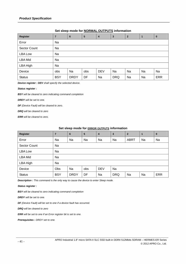
Set sleep mode for NORMAL OUTPUTS information
Register 7 6 5 4 3 2 1 0
Error Na
Sector Count Na
LBA Low Na
LBA Mid Na
LBA High Na
Device obs Na obs DEV Na Na Na Na
Status BSY DRDY DF Na DRQ Na Na ERR
Device register : DEV shall specify the selected device.
Status register :
BSY will be cleared to zero indicating command completion
DRDY will be set to one.
DF (Device Fault) will be cleared to zero.
DRQ will be cleared to zero
ERR will be cleared to zero.
Set sleep mode for ERROR OUTPUTS information
Register 7 6 5 4 3 2 1 0
Error Na Na Na Na Na ABRT Na Na
Sector Count Na
LBA Low Na
LBA Mid Na
LBA High Na
Device Obs Na obs DEV Na
Status BSY DRDY DF Na DRQ Na Na ERR
Description : This command is the only way to cause the device to enter Sleep mode.
Status register :
BSY will be cleared to zero indicating command completion
DRDY will be set to one.
DF (Device Fault) will be set to one if a device fault has occurred.
DRQ will be cleared to zero
ERR will be set to one if an Error register bit is set to one.
Prerequisites : DRDY set to one.
- 41 - APRO Industrial 1.8” micro SATA II SLC SSD built-in DDRII 512Mbits SDRAM – HERMES-ER Series © 2012 APRO Co., Ltd.
Product Specification
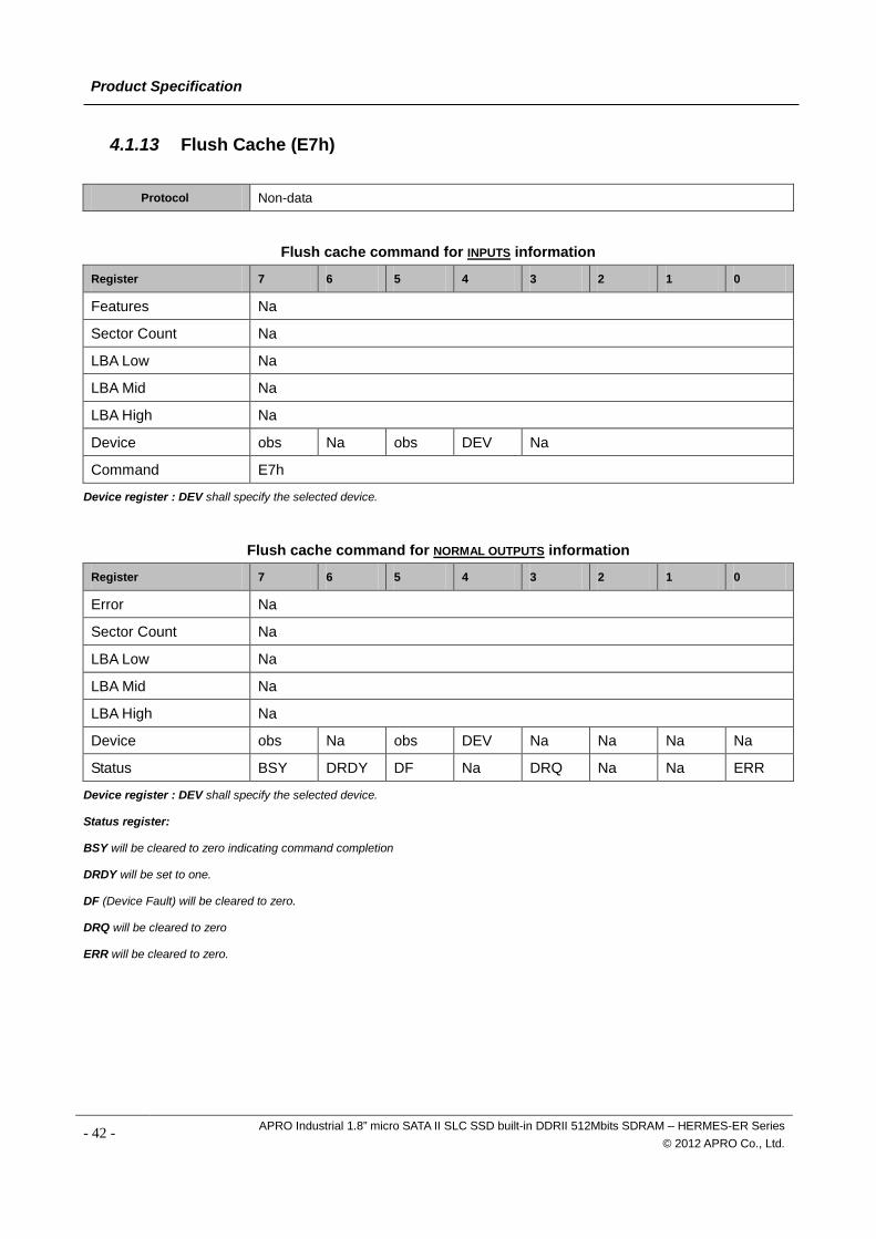
4.1.13 Flush Cache (E7h)
Protocol Non-data
Flush cache command for INPUTS information
Register 7 6 5 4 3 2 1 0
Features Na
Sector Count Na
LBA Low Na
LBA Mid Na
LBA High Na
Device obs Na obs DEV Na
Command E7h
Device register : DEV shall specify the selected device.
Flush cache command for NORMAL OUTPUTS information
Register 7 6 5 4 3 2 1 0
Error Na
Sector Count Na
LBA Low Na
LBA Mid Na
LBA High Na
Device obs Na obs DEV Na Na Na Na
Status BSY DRDY DF Na DRQ Na Na ERR
Device register : DEV shall specify the selected device.
Status register:
BSY will be cleared to zero indicating command completion
DRDY will be set to one.
DF (Device Fault) will be cleared to zero.
DRQ will be cleared to zero
ERR will be cleared to zero.
- 42 - APRO Industrial 1.8” micro SATA II SLC SSD built-in DDRII 512Mbits SDRAM – HERMES-ER Series © 2012 APRO Co., Ltd.
Product Specification
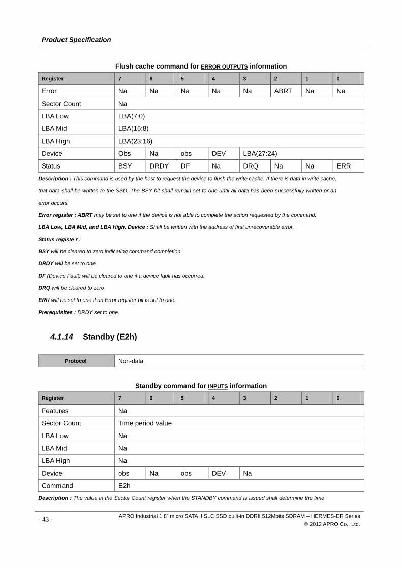
Flush cache command for ERROR OUTPUTS information
Register 7 6 5 4 3 2 1 0
Error Na Na Na Na Na ABRT Na Na
Sector Count Na
LBA Low LBA(7:0)
LBA Mid LBA(15:8)
LBA High LBA(23:16)
Device Obs Na obs DEV LBA(27:24)
Status BSY DRDY DF Na DRQ Na Na ERR
Description : This command is used by the host to request the device to flush the write cache. If there is data in write cache,
that data shall be written to the SSD. The BSY bit shall remain set to one until all data has been successfully written or an
error occurs.
Error register : ABRT may be set to one if the device is not able to complete the action requested by the command.
LBA Low, LBA Mid, and LBA High, Device : Shall be written with the address of first unrecoverable error.
Status registe r :
BSY will be cleared to zero indicating command completion
DRDY will be set to one.
DF (Device Fault) will be cleared to one if a device fault has occurred.
DRQ will be cleared to zero
ERR will be set to one if an Error register bit is set to one.
Prerequisites : DRDY set to one.
4.1.14 Standby (E2h)
Protocol Non-data
Standby command for INPUTS information
Register 7 6 5 4 3 2 1 0
Features Na
Sector Count Time period value
LBA Low Na
LBA Mid Na
LBA High Na
Device obs Na obs DEV Na
Command E2h
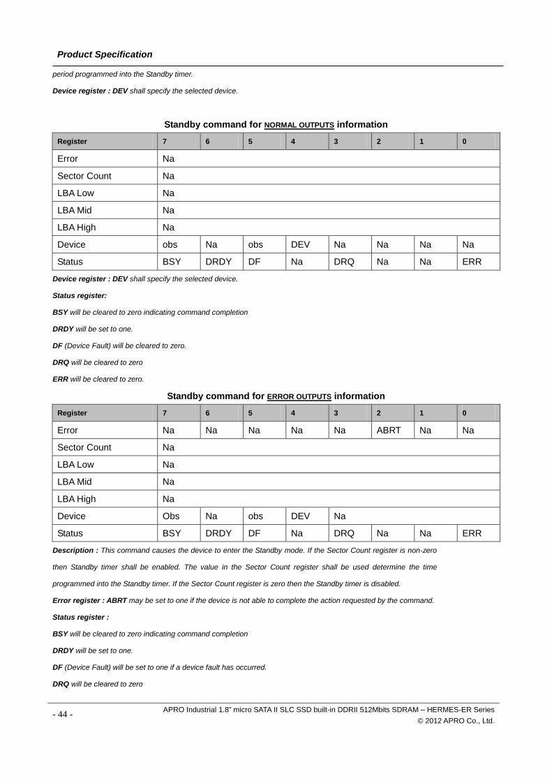
Description : The value in the Sector Count register when the STANDBY command is issued shall determine the time
- 43 - APRO Industrial 1.8” micro SATA II SLC SSD built-in DDRII 512Mbits SDRAM – HERMES-ER Series © 2012 APRO Co., Ltd.
Product Specification
period programmed into the Standby timer.
Device register : DEV shall specify the selected device.
Standby command for NORMAL OUTPUTS information
Register 7 6 5 4 3 2 1 0
Error Na
Sector Count Na
LBA Low Na
LBA Mid Na
LBA High Na
Device obs Na obs DEV Na Na Na Na
Status BSY DRDY DF Na DRQ Na Na ERR
Device register : DEV shall specify the selected device.
Status register:
BSY will be cleared to zero indicating command completion
DRDY will be set to one.
DF (Device Fault) will be cleared to zero.
DRQ will be cleared to zero
ERR will be cleared to zero.
Standby command for ERROR OUTPUTS information
Register 7 6 5 4 3 2 1 0
Error Na Na Na Na Na ABRT Na Na
Sector Count Na
LBA Low Na
LBA Mid Na
LBA High Na
Device Obs Na obs DEV Na
Status BSY DRDY DF Na DRQ Na Na ERR
Description : This command causes the device to enter the Standby mode. If the Sector Count register is non-zero
then Standby timer shall be enabled. The value in the Sector Count register shall be used determine the time
programmed into the Standby timer. If the Sector Count register is zero then the Standby timer is disabled.
Error register : ABRT may be set to one if the device is not able to complete the action requested by the command.
Status register :
BSY will be cleared to zero indicating command completion
DRDY will be set to one.
DF (Device Fault) will be set to one if a device fault has occurred.
DRQ will be cleared to zero
- 44 - APRO Industrial 1.8” micro SATA II SLC SSD built-in DDRII 512Mbits SDRAM – HERMES-ER Series © 2012 APRO Co., Ltd.
Product Specification
ERR will be set to one if an Error register bit is set to one.
Prerequisites : DRDY set to one.
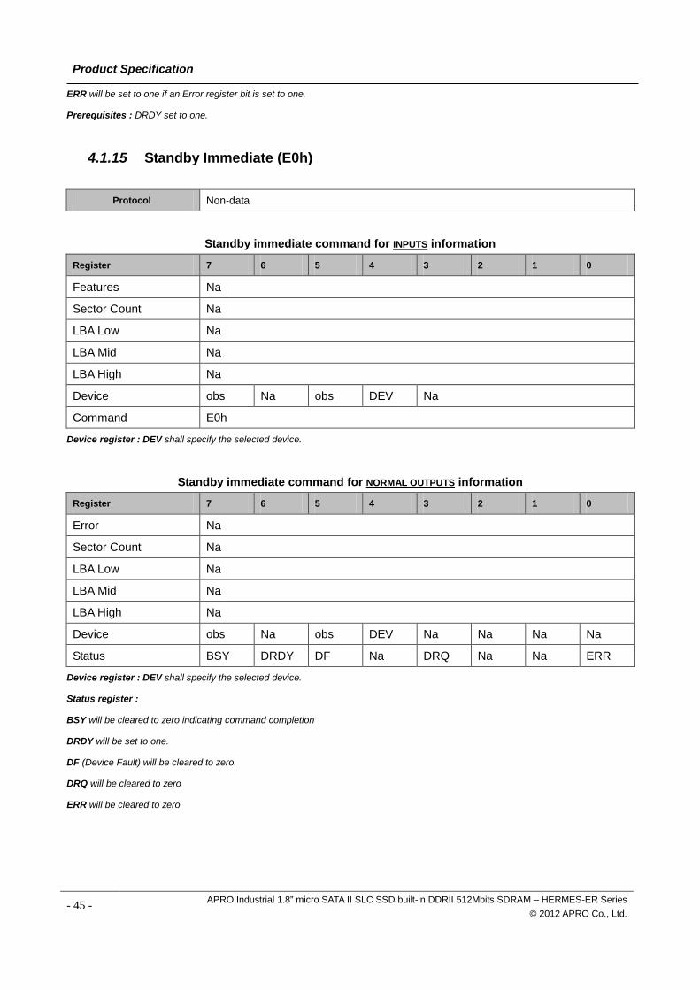
4.1.15 Standby Immediate (E0h)
Protocol Non-data
Standby immediate command for INPUTS information
Register 7 6 5 4 3 2 1 0
Features Na
Sector Count Na
LBA Low Na
LBA Mid Na
LBA High Na
Device obs Na obs DEV Na
Command E0h
Device register : DEV shall specify the selected device.
Standby immediate command for NORMAL OUTPUTS information
Register 7 6 5 4 3 2 1 0
Error Na
Sector Count Na
LBA Low Na
LBA Mid Na
LBA High Na
Device obs Na obs DEV Na Na Na Na
Status BSY DRDY DF Na DRQ Na Na ERR
Device register : DEV shall specify the selected device.
Status register :
BSY will be cleared to zero indicating command completion
DRDY will be set to one.
DF (Device Fault) will be cleared to zero.
DRQ will be cleared to zero
ERR will be cleared to zero
- 45 - APRO Industrial 1.8” micro SATA II SLC SSD built-in DDRII 512Mbits SDRAM – HERMES-ER Series © 2012 APRO Co., Ltd.
Product Specification
Standby immediate command for ERROR OUTPUTS information
Register 7 6 5 4 3 2 1 0
Error Na Na Na Na Na ABRT Na Na
Sector Count Na
LBA Low Na
LBA Mid Na
LBA High Na
Device Obs Na obs DEV Na
Status BSY DRDY DF Na DRQ Na Na ERR
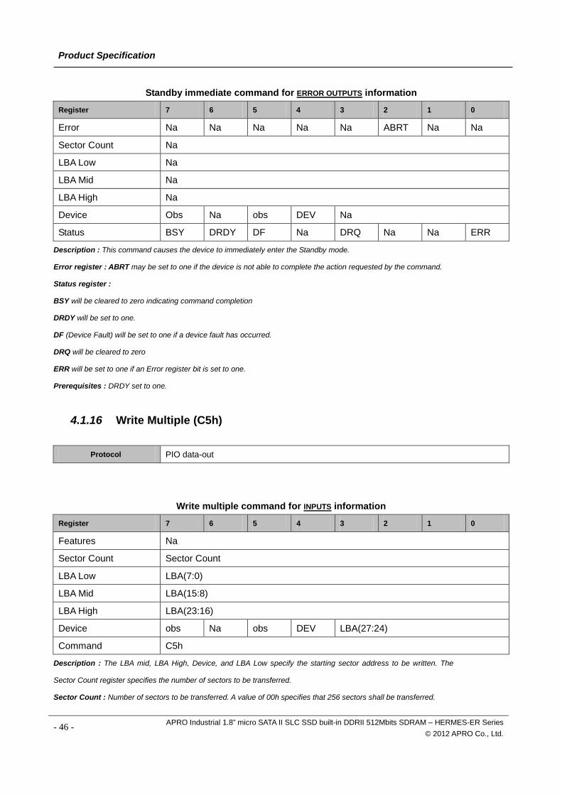
Description : This command causes the device to immediately enter the Standby mode.
Error register : ABRT may be set to one if the device is not able to complete the action requested by the command.
Status register :
BSY will be cleared to zero indicating command completion
DRDY will be set to one.
DF (Device Fault) will be set to one if a device fault has occurred.
DRQ will be cleared to zero
ERR will be set to one if an Error register bit is set to one.
Prerequisites : DRDY set to one.
4.1.16 Write Multiple (C5h)
Protocol PIO data-out
Write multiple command for INPUTS information
Register 7 6 5 4 3 2 1 0
Features Na
Sector Count Sector Count
LBA Low LBA(7:0)
LBA Mid LBA(15:8)
LBA High LBA(23:16)
Device obs Na obs DEV LBA(27:24)
Command C5h
Description : The LBA mid, LBA High, Device, and LBA Low specify the starting sector address to be written. The
Sector Count register specifies the number of sectors to be transferred.
Sector Count : Number of sectors to be transferred. A value of 00h specifies that 256 sectors shall be transferred.
- 46 - APRO Industrial 1.8” micro SATA II SLC SSD built-in DDRII 512Mbits SDRAM – HERMES-ER Series © 2012 APRO Co., Ltd.
Product Specification
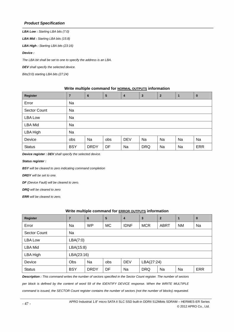
LBA Low : Starting LBA bits (7:0)
LBA Mid : Starting LBA bits (15:8)
LBA High : Starting LBA bits (23:16)
Device :
The LBA bit shall be set to one to specify the address is an LBA.
DEV shall specify the selected device.
Bits(3:0) starting LBA bits (27:24)
Write multiple command for NORMAL OUTPUTS information
Register 7 6 5 4 3 2 1 0
Error Na
Sector Count Na
LBA Low Na
LBA Mid Na
LBA High Na
Device obs Na obs DEV Na Na Na Na
Status BSY DRDY DF Na DRQ Na Na ERR
Device register : DEV shall specify the selected device.
Status register :
BSY will be cleared to zero indicating command completion
DRDY will be set to one.
DF (Device Fault) will be cleared to zero.
DRQ will be cleared to zero
ERR will be cleared to zero.
Write multiple command for ERROR OUTPUTS information
Register 7 6 5 4 3 2 1 0
Error Na WP MC IDNF MCR ABRT NM Na
Sector Count Na
LBA Low LBA(7:0)
LBA Mid LBA(15:8)
LBA High LBA(23:16)
Device Obs Na obs DEV LBA(27:24)
Status BSY DRDY DF Na DRQ Na Na ERR
Description : This command writes the number of sectors specified in the Sector Count register. The number of sectors
per block is defined by the content of word 59 of the IDENTIFY DEVICE response. When the WRITE MULTIPLE
command is issued, the SECTOR Count register contains the number of sectors (not the number of blocks) requested.
- 47 - APRO Industrial 1.8” micro SATA II SLC SSD built-in DDRII 512Mbits SDRAM – HERMES-ER Series © 2012 APRO Co., Ltd.
Product Specification
The device shall interrupt for each DRQ block transferred. IF the number of requested sectors is not evenly divisible by
the block count, as many full blocks as possible are transferred, followed by a final, partial block transfer. The partial
block transfer is for n sectors, where: N = Remainder ( sector count / block count).
If the WRITE MULTIPLE command is received when WRITE MULTIPLE commands are disabled, the Write Multiple
operation shall be rejected with command aborted.
Device errors encountered during WRITE MULTIPLE commands are posted after the attempted device write of the block
or partial block transferred. The command ends with the sector in error, even if the error was in the middle of a block.
Subsequent blocks are not transferred in the event of an error.
The contents of the Command Block Registers following the transfer of a data block that had a sector in error are
undefined. The host should retry the transfer as individual requests to obtain valid error information. Interrupt pending is
set when the DRQ bit is set to one at the beginning of each block or partial block.
An unrecoverable error encountered during the execution of this command results in the termination of the command.
The Command Block register contain the address of the sector where the first unrecoverable error occurred. The amount
of data transferred is indeterminate.
Error register : IDNF shall be set to one if a user-accessible address could not be found. IDNF shall be set to one if an
address outside of the range user-accessible address is requested if command aborted is not returned.
ABRT shall be set to one if an error, include an ICRC error, has occurred during an Ultra DMA data transfer. ABRT shall be
set to one if an address outside of the range of user-accessible address is requested if IDNF is not set to one.
LBA Low, LBA Mid, and LBA High, Device : Shall be written with the address of first unrecoverable error.
Status register :
BSY will be cleared to zero indicating command completion
DRDY will be set to one. (If bit 8 of IDENTIFY DEVICE word 59 is cleared to zero, a successful SET MULTIPLE MODE
command shall proceed a WRITE MULTIPLE command.)
DF (Device Fault) will be set to one if a device fault has occurred.
DRQ will be cleared to zero
ERR will be set to one if an Error register bit is set to one.
Prerequisites : DRDY set to one. If bit 8 of IDENTIFY DEVICE word 59 is cleared to zero, a successful SET
MULTIPLE MODE command shall proceed a WRITE MULTIPLE command.
- 48 - APRO Industrial 1.8” micro SATA II SLC SSD built-in DDRII 512Mbits SDRAM – HERMES-ER Series © 2012 APRO Co., Ltd.
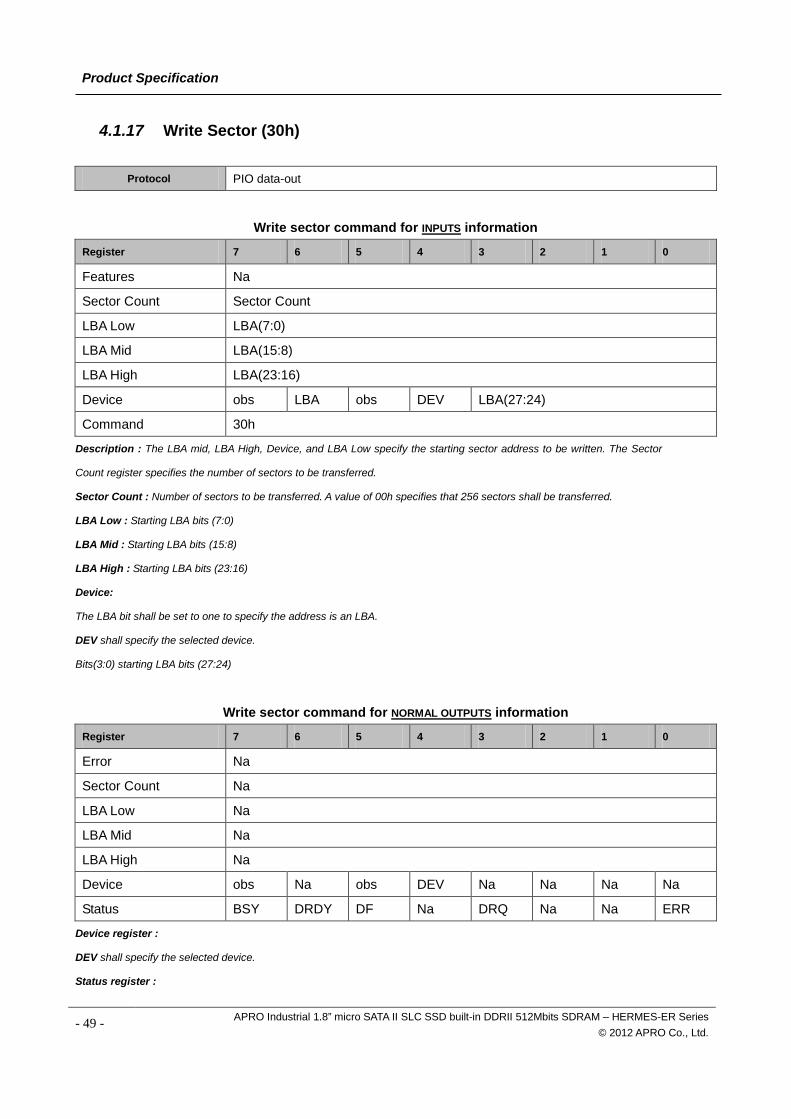
Product Specification
4.1.17 Write Sector (30h)
Protocol PIO data-out
Write sector command for INPUTS information
Register 7 6 5 4 3 2 1 0
Features Na
Sector Count Sector Count
LBA Low LBA(7:0)
LBA Mid LBA(15:8)
LBA High LBA(23:16)
Device obs LBA obs DEV LBA(27:24)
Command 30h
Description : The LBA mid, LBA High, Device, and LBA Low specify the starting sector address to be written. The Sector
Count register specifies the number of sectors to be transferred.
Sector Count : Number of sectors to be transferred. A value of 00h specifies that 256 sectors shall be transferred.
LBA Low : Starting LBA bits (7:0)
LBA Mid : Starting LBA bits (15:8)
LBA High : Starting LBA bits (23:16)
Device:
The LBA bit shall be set to one to specify the address is an LBA.
DEV shall specify the selected device.
Bits(3:0) starting LBA bits (27:24)
Write sector command for NORMAL OUTPUTS information
Register 7 6 5 4 3 2 1 0
Error Na
Sector Count Na
LBA Low Na
LBA Mid Na
LBA High Na
Device obs Na obs DEV Na Na Na Na
Status BSY DRDY DF Na DRQ Na Na ERR
Device register :
DEV shall specify the selected device.
Status register :
- 49 - APRO Industrial 1.8” micro SATA II SLC SSD built-in DDRII 512Mbits SDRAM – HERMES-ER Series © 2012 APRO Co., Ltd.
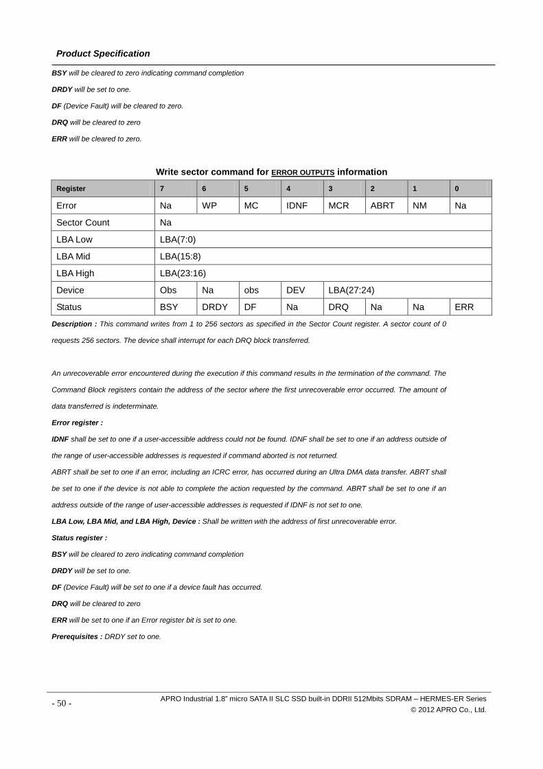
Product Specification
BSY will be cleared to zero indicating command completion
DRDY will be set to one.
DF (Device Fault) will be cleared to zero.
DRQ will be cleared to zero
ERR will be cleared to zero.
Write sector command for ERROR OUTPUTS information
Register 7 6 5 4 3 2 1 0
Error Na WP MC IDNF MCR ABRT NM Na
Sector Count Na
LBA Low LBA(7:0)
LBA Mid LBA(15:8)
LBA High LBA(23:16)
Device Obs Na obs DEV LBA(27:24)
Status BSY DRDY DF Na DRQ Na Na ERR
Description : This command writes from 1 to 256 sectors as specified in the Sector Count register. A sector count of 0
requests 256 sectors. The device shall interrupt for each DRQ block transferred.
An unrecoverable error encountered during the execution if this command results in the termination of the command. The
Command Block registers contain the address of the sector where the first unrecoverable error occurred. The amount of
data transferred is indeterminate.
Error register :
IDNF shall be set to one if a user-accessible address could not be found. IDNF shall be set to one if an address outside of
the range of user-accessible addresses is requested if command aborted is not returned.
ABRT shall be set to one if an error, including an ICRC error, has occurred during an Ultra DMA data transfer. ABRT shall
be set to one if the device is not able to complete the action requested by the command. ABRT shall be set to one if an
address outside of the range of user-accessible addresses is requested if IDNF is not set to one.
LBA Low, LBA Mid, and LBA High, Device : Shall be written with the address of first unrecoverable error.
Status register :
BSY will be cleared to zero indicating command completion
DRDY will be set to one.
DF (Device Fault) will be set to one if a device fault has occurred.
DRQ will be cleared to zero
ERR will be set to one if an Error register bit is set to one.
Prerequisites : DRDY set to one.
- 50 - APRO Industrial 1.8” micro SATA II SLC SSD built-in DDRII 512Mbits SDRAM – HERMES-ER Series © 2012 APRO Co., Ltd.
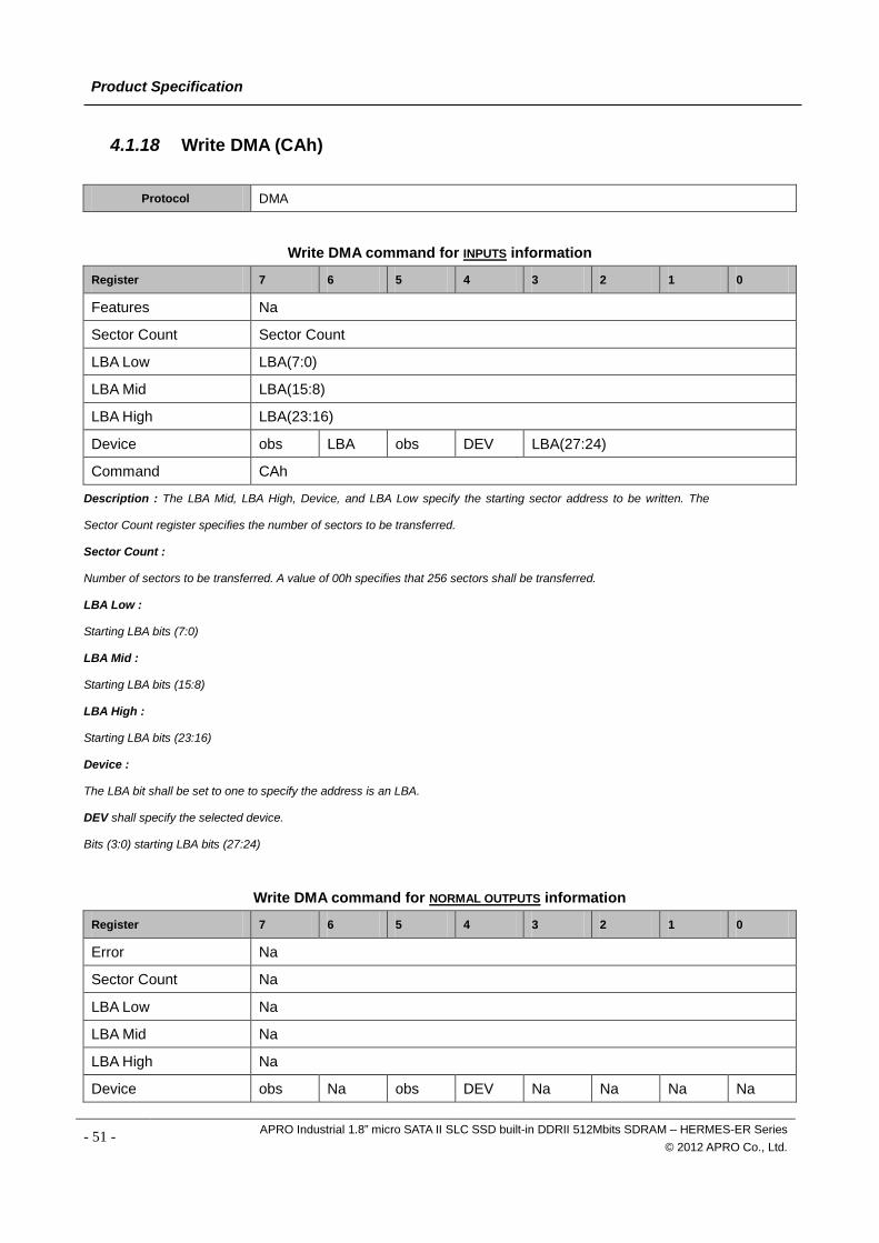
Product Specification
4.1.18 Write DMA (CAh)
Protocol DMA
Write DMA command for INPUTS information
Register 7 6 5 4 3 2 1 0
Features Na
Sector Count Sector Count
LBA Low LBA(7:0)
LBA Mid LBA(15:8)
LBA High LBA(23:16)
Device obs LBA obs DEV LBA(27:24)
Command CAh
Description : The LBA Mid, LBA High, Device, and LBA Low specify the starting sector address to be written. The
Sector Count register specifies the number of sectors to be transferred.
Sector Count :
Number of sectors to be transferred. A value of 00h specifies that 256 sectors shall be transferred.
LBA Low :
Starting LBA bits (7:0)
LBA Mid :
Starting LBA bits (15:8)
LBA High :
Starting LBA bits (23:16)
Device :
The LBA bit shall be set to one to specify the address is an LBA.
DEV shall specify the selected device.
Bits (3:0) starting LBA bits (27:24)
Write DMA command for NORMAL OUTPUTS information
Register 7 6 5 4 3 2 1 0
Error Na
Sector Count Na
LBA Low Na
LBA Mid Na
LBA High Na
Device obs Na obs DEV Na Na Na Na
- 51 - APRO Industrial 1.8” micro SATA II SLC SSD built-in DDRII 512Mbits SDRAM – HERMES-ER Series © 2012 APRO Co., Ltd.
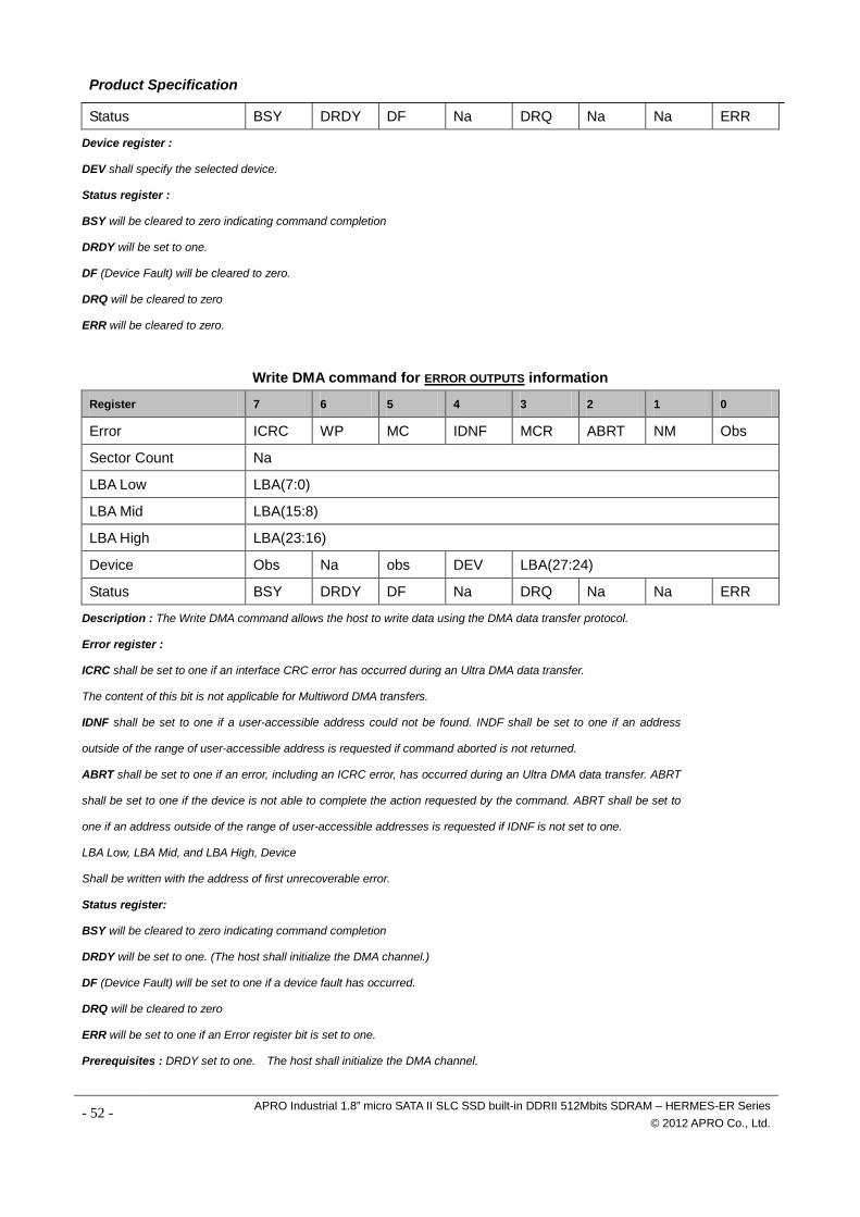
Product Specification
Status BSY DRDY DF Na DRQ Na Na ERR
Device register :
DEV shall specify the selected device.
Status register :
BSY will be cleared to zero indicating command completion
DRDY will be set to one.
DF (Device Fault) will be cleared to zero.
DRQ will be cleared to zero
ERR will be cleared to zero.
Write DMA command for ERROR OUTPUTS information
Register 7 6 5 4 3 2 1 0
Error ICRC WP MC IDNF MCR ABRT NM Obs
Sector Count Na
LBA Low LBA(7:0)
LBA Mid LBA(15:8)
LBA High LBA(23:16)
Device Obs Na obs DEV LBA(27:24)
Status BSY DRDY DF Na DRQ Na Na ERR
Description : The Write DMA command allows the host to write data using the DMA data transfer protocol.
Error register :
ICRC shall be set to one if an interface CRC error has occurred during an Ultra DMA data transfer.
The content of this bit is not applicable for Multiword DMA transfers.
IDNF shall be set to one if a user-accessible address could not be found. INDF shall be set to one if an address
outside of the range of user-accessible address is requested if command aborted is not returned.
ABRT shall be set to one if an error, including an ICRC error, has occurred during an Ultra DMA data transfer. ABRT
shall be set to one if the device is not able to complete the action requested by the command. ABRT shall be set to
one if an address outside of the range of user-accessible addresses is requested if IDNF is not set to one.
LBA Low, LBA Mid, and LBA High, Device
Shall be written with the address of first unrecoverable error.
Status register:
BSY will be cleared to zero indicating command completion
DRDY will be set to one. (The host shall initialize the DMA channel.)
DF (Device Fault) will be set to one if a device fault has occurred.
DRQ will be cleared to zero
ERR will be set to one if an Error register bit is set to one.
Prerequisites : DRDY set to one. The host shall initialize the DMA channel.
- 52 - APRO Industrial 1.8” micro SATA II SLC SSD built-in DDRII 512Mbits SDRAM – HERMES-ER Series © 2012 APRO Co., Ltd.
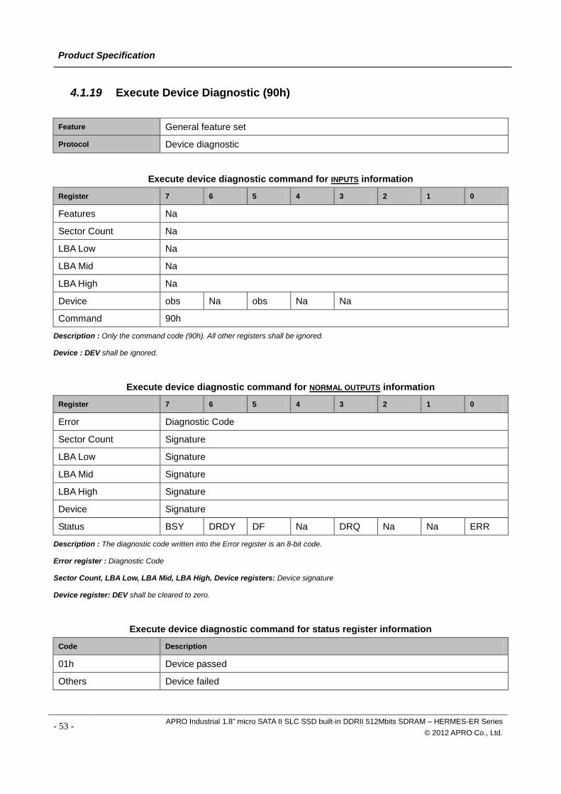
Product Specification
4.1.19 Execute Device Diagnostic (90h)
Feature General feature set Protocol Device diagnostic
Execute device diagnostic command for INPUTS information
Register 7 6 5 4 3 2 1 0
Features Na
Sector Count Na
LBA Low Na
LBA Mid Na
LBA High Na
Device obs Na obs Na Na
Command 90h
Description : Only the command code (90h). All other registers shall be ignored.
Device : DEV shall be ignored.
Execute device diagnostic command for NORMAL OUTPUTS information
Register 7 6 5 4 3 2 1 0
Error Diagnostic Code
Sector Count Signature
LBA Low Signature
LBA Mid Signature
LBA High Signature
Device Signature
Status BSY DRDY DF Na DRQ Na Na ERR
Description : The diagnostic code written into the Error register is an 8-bit code.
Error register : Diagnostic Code
Sector Count, LBA Low, LBA Mid, LBA High, Device registers: Device signature
Device register: DEV shall be cleared to zero.
Execute device diagnostic command for status register information
Code Description
01h Device passed
Others Device failed
- 53 - APRO Industrial 1.8” micro SATA II SLC SSD built-in DDRII 512Mbits SDRAM – HERMES-ER Series © 2012 APRO Co., Ltd.
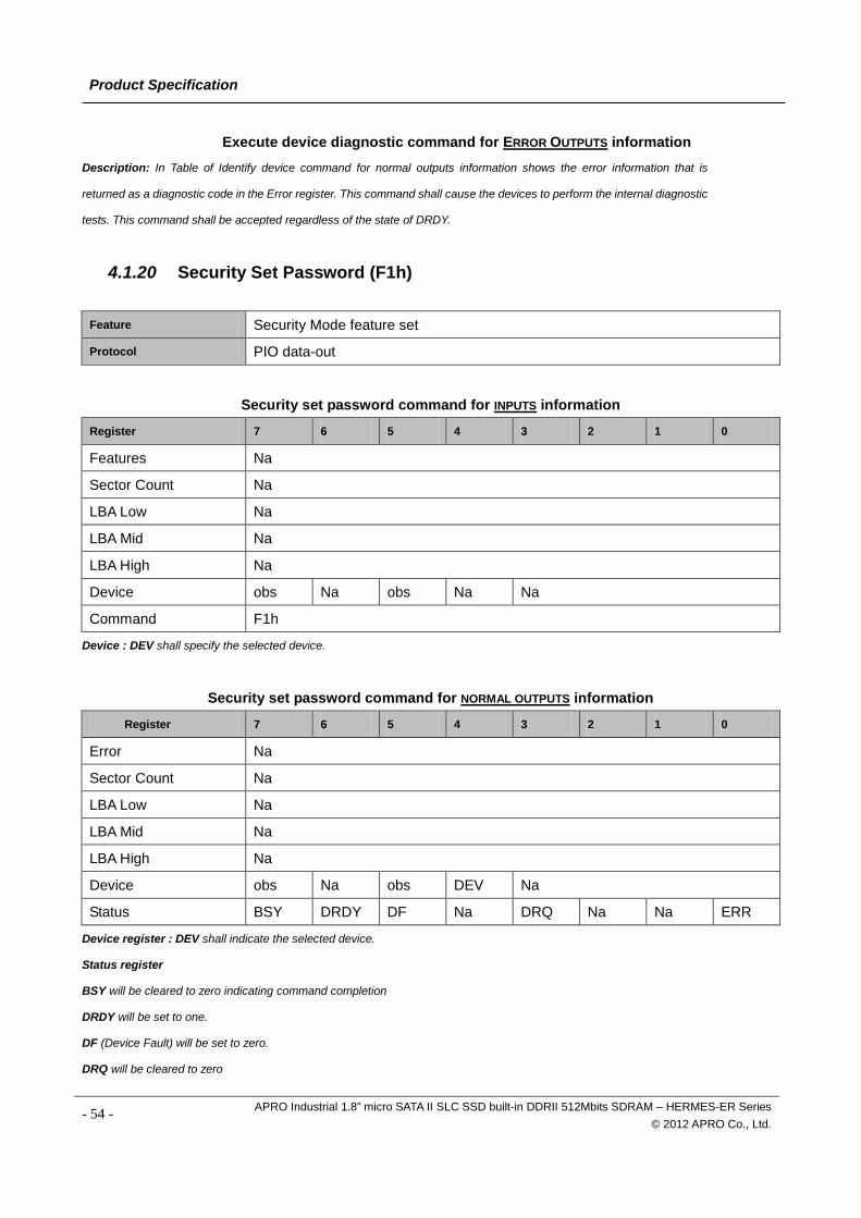
Product Specification
Execute device diagnostic command for ERROR OUTPUTS information Description: In Table of Identify device command for normal outputs information shows the error information that is
returned as a diagnostic code in the Error register. This command shall cause the devices to perform the internal diagnostic
tests. This command shall be accepted regardless of the state of DRDY.
4.1.20 Security Set Password (F1h)
Feature Security Mode feature set Protocol PIO data-out
Security set password command for INPUTS information
Register 7 6 5 4 3 2 1 0
Features Na
Sector Count Na
LBA Low Na
LBA Mid Na
LBA High Na
Device obs Na obs Na Na
Command F1h
Device : DEV shall specify the selected device.
Security set password command for NORMAL OUTPUTS information
Register 7 6 5 4 3 2 1 0
Error Na
Sector Count Na
LBA Low Na
LBA Mid Na
LBA High Na
Device obs Na obs DEV Na
Status BSY DRDY DF Na DRQ Na Na ERR
Device register : DEV shall indicate the selected device.
Status register
BSY will be cleared to zero indicating command completion
DRDY will be set to one.
DF (Device Fault) will be set to zero.
DRQ will be cleared to zero
- 54 - APRO Industrial 1.8” micro SATA II SLC SSD built-in DDRII 512Mbits SDRAM – HERMES-ER Series © 2012 APRO Co., Ltd.
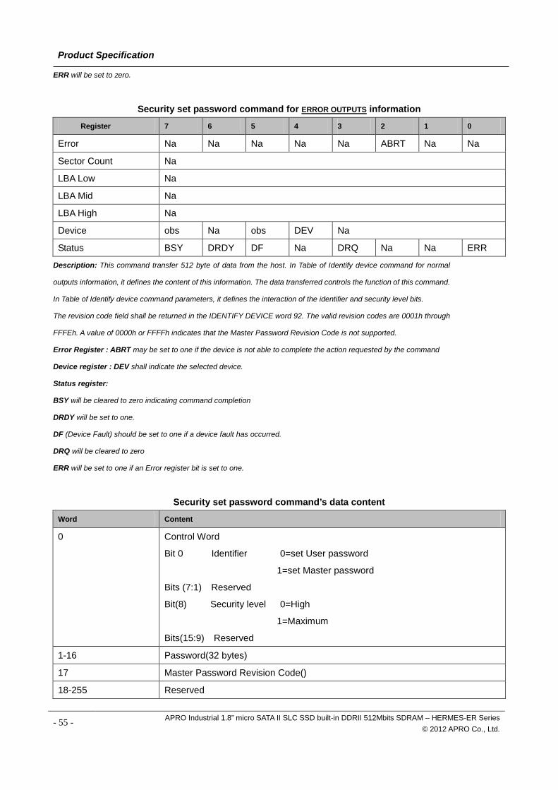
Product Specification
ERR will be set to zero.
Security set password command for ERROR OUTPUTS information
Register 7 6 5 4 3 2 1 0
Error Na Na Na Na Na ABRT Na Na
Sector Count Na
LBA Low Na
LBA Mid Na
LBA High Na
Device obs Na obs DEV Na
Status BSY DRDY DF Na DRQ Na Na ERR
Description: This command transfer 512 byte of data from the host. In Table of Identify device command for normal
outputs information, it defines the content of this information. The data transferred controls the function of this command.
In Table of Identify device command parameters, it defines the interaction of the identifier and security level bits.
The revision code field shall be returned in the IDENTIFY DEVICE word 92. The valid revision codes are 0001h through
FFFEh. A value of 0000h or FFFFh indicates that the Master Password Revision Code is not supported.
Error Register : ABRT may be set to one if the device is not able to complete the action requested by the command
Device register : DEV shall indicate the selected device.
Status register:
BSY will be cleared to zero indicating command completion
DRDY will be set to one.
DF (Device Fault) should be set to one if a device fault has occurred.
DRQ will be cleared to zero
ERR will be set to one if an Error register bit is set to one.
Security set password command’s data content
Word Content
0 Control Word
Bit 0 Identifier 0=set User password
1=set Master password
Bits (7:1) Reserved
Bit(8) Security level 0=High
1=Maximum
Bits(15:9) Reserved
1-16 Password(32 bytes)
17 Master Password Revision Code()
18-255 Reserved
- 55 - APRO Industrial 1.8” micro SATA II SLC SSD built-in DDRII 512Mbits SDRAM – HERMES-ER Series © 2012 APRO Co., Ltd.
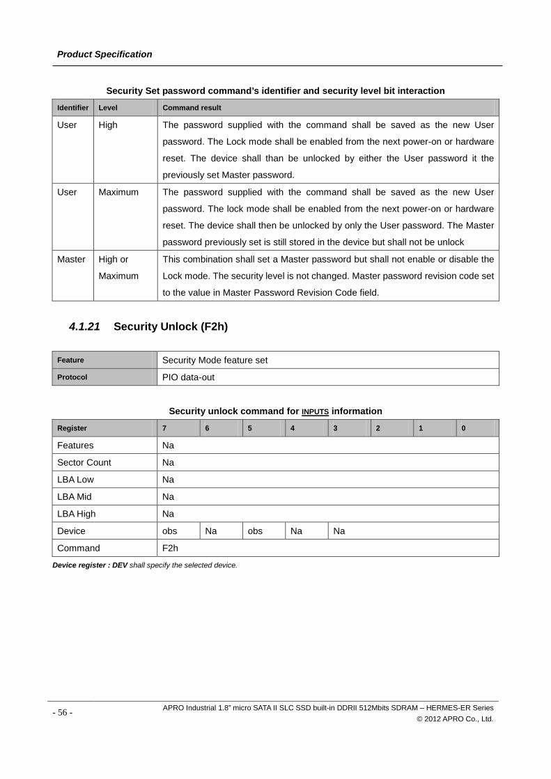
Product Specification
Security Set password command’s identifier and security level bit interaction
Identifier Level Command result
User High The password supplied with the command shall be saved as the new User
password. The Lock mode shall be enabled from the next power-on or hardware
reset. The device shall than be unlocked by either the User password it the
previously set Master password.
User Maximum The password supplied with the command shall be saved as the new User
password. The lock mode shall be enabled from the next power-on or hardware
reset. The device shall then be unlocked by only the User password. The Master
password previously set is still stored in the device but shall not be unlock
Master High or
Maximum
This combination shall set a Master password but shall not enable or disable the
Lock mode. The security level is not changed. Master password revision code set
to the value in Master Password Revision Code field.
4.1.21 Security Unlock (F2h)
Feature Security Mode feature set Protocol PIO data-out
Security unlock command for INPUTS information
Register 7 6 5 4 3 2 1 0
Features Na
Sector Count Na
LBA Low Na
LBA Mid Na
LBA High Na
Device obs Na obs Na Na
Command F2h
Device register : DEV shall specify the selected device.
- 56 - APRO Industrial 1.8” micro SATA II SLC SSD built-in DDRII 512Mbits SDRAM – HERMES-ER Series © 2012 APRO Co., Ltd.
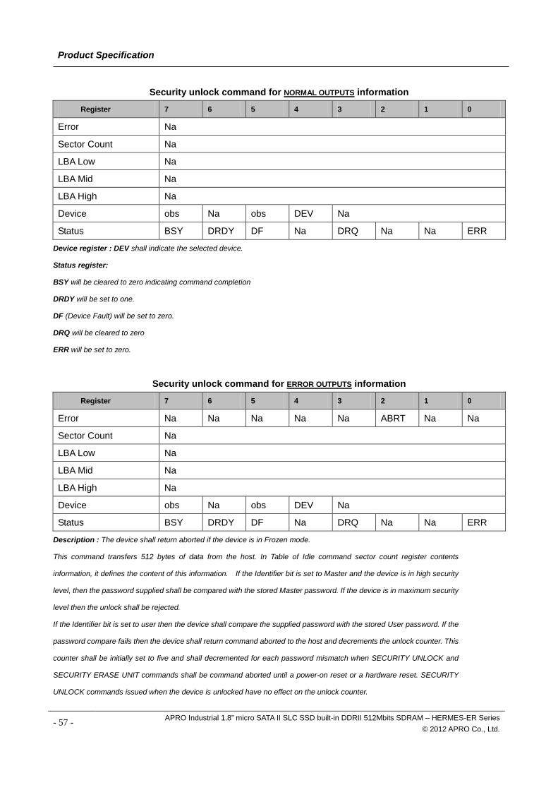
Product Specification
Security unlock command for NORMAL OUTPUTS information
Register 7 6 5 4 3 2 1 0
Error Na
Sector Count Na
LBA Low Na
LBA Mid Na
LBA High Na
Device obs Na obs DEV Na
Status BSY DRDY DF Na DRQ Na Na ERR
Device register : DEV shall indicate the selected device.
Status register:
BSY will be cleared to zero indicating command completion
DRDY will be set to one.
DF (Device Fault) will be set to zero.
DRQ will be cleared to zero
ERR will be set to zero.
Security unlock command for ERROR OUTPUTS information
Register 7 6 5 4 3 2 1 0
Error Na Na Na Na Na ABRT Na Na
Sector Count Na
LBA Low Na
LBA Mid Na
LBA High Na
Device obs Na obs DEV Na
Status BSY DRDY DF Na DRQ Na Na ERR
Description : The device shall return aborted if the device is in Frozen mode.
This command transfers 512 bytes of data from the host. In Table of Idle command sector count register contents
information, it defines the content of this information. If the Identifier bit is set to Master and the device is in high security
level, then the password supplied shall be compared with the stored Master password. If the device is in maximum security
level then the unlock shall be rejected.
If the Identifier bit is set to user then the device shall compare the supplied password with the stored User password. If the
password compare fails then the device shall return command aborted to the host and decrements the unlock counter. This
counter shall be initially set to five and shall decremented for each password mismatch when SECURITY UNLOCK and
SECURITY ERASE UNIT commands shall be command aborted until a power-on reset or a hardware reset. SECURITY
UNLOCK commands issued when the device is unlocked have no effect on the unlock counter.
- 57 - APRO Industrial 1.8” micro SATA II SLC SSD built-in DDRII 512Mbits SDRAM – HERMES-ER Series © 2012 APRO Co., Ltd.
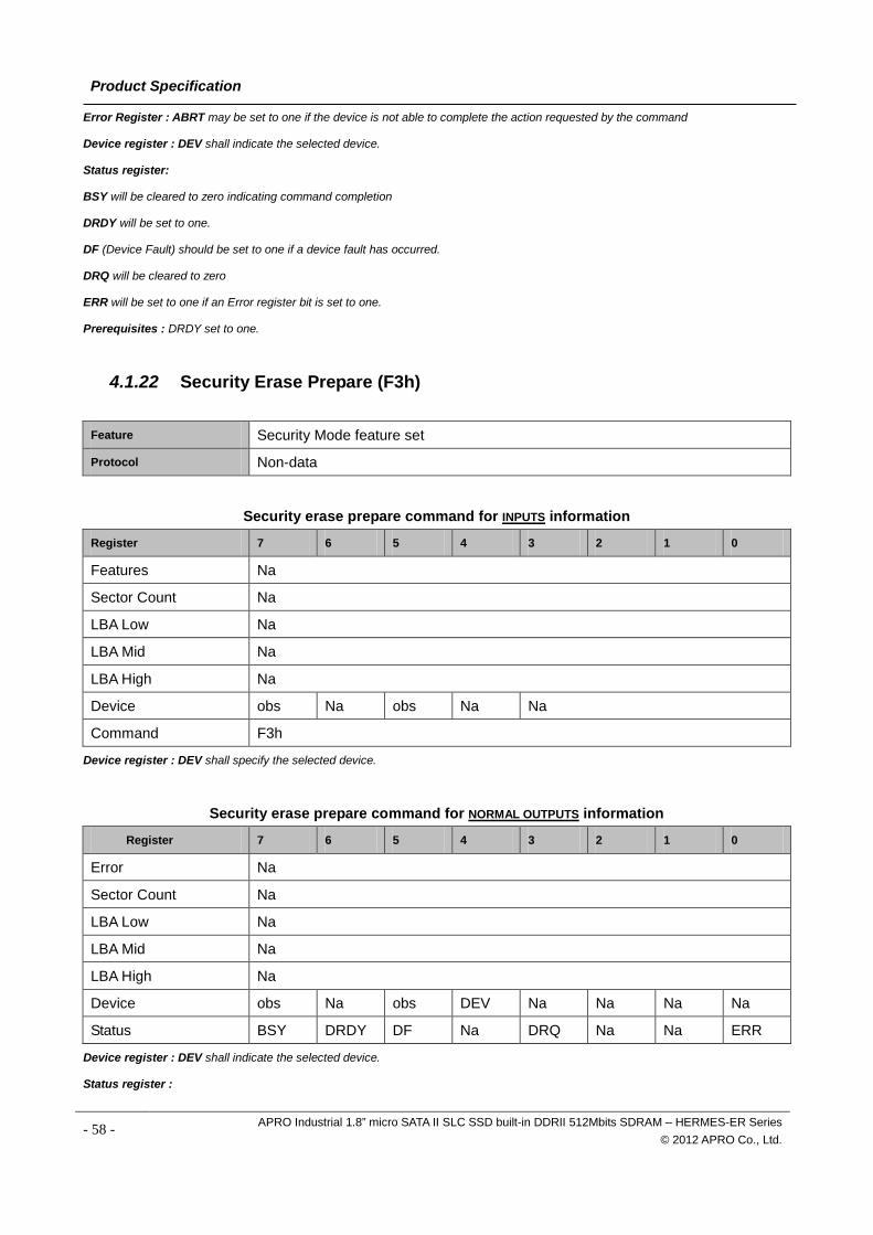
Product Specification
Error Register : ABRT may be set to one if the device is not able to complete the action requested by the command
Device register : DEV shall indicate the selected device.
Status register:
BSY will be cleared to zero indicating command completion
DRDY will be set to one.
DF (Device Fault) should be set to one if a device fault has occurred.
DRQ will be cleared to zero
ERR will be set to one if an Error register bit is set to one.
Prerequisites : DRDY set to one.
4.1.22 Security Erase Prepare (F3h)
Feature Security Mode feature set Protocol Non-data
Security erase prepare command for INPUTS information
Register 7 6 5 4 3 2 1 0
Features Na
Sector Count Na
LBA Low Na
LBA Mid Na
LBA High Na
Device obs Na obs Na Na
Command F3h
Device register : DEV shall specify the selected device.
Security erase prepare command for NORMAL OUTPUTS information
Register 7 6 5 4 3 2 1 0
Error Na
Sector Count Na
LBA Low Na
LBA Mid Na
LBA High Na
Device obs Na obs DEV Na Na Na Na
Status BSY DRDY DF Na DRQ Na Na ERR
Device register : DEV shall indicate the selected device.
Status register :
- 58 - APRO Industrial 1.8” micro SATA II SLC SSD built-in DDRII 512Mbits SDRAM – HERMES-ER Series © 2012 APRO Co., Ltd.
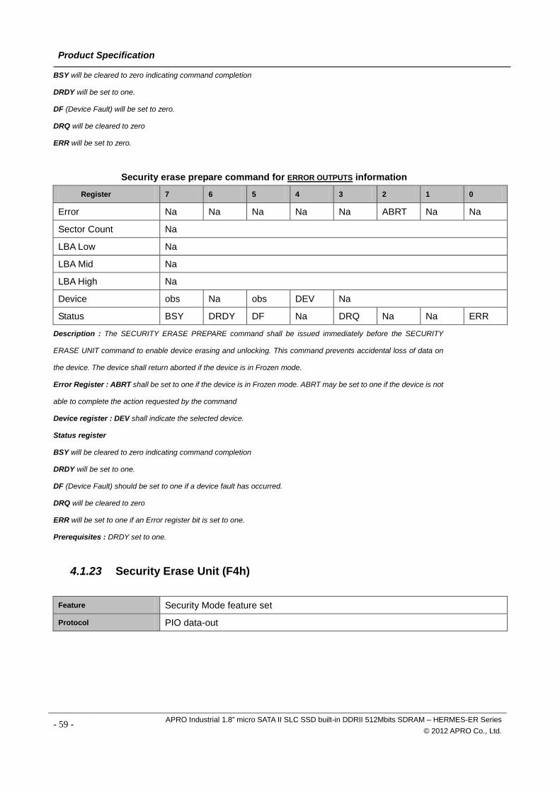
Product Specification
BSY will be cleared to zero indicating command completion
DRDY will be set to one.
DF (Device Fault) will be set to zero.
DRQ will be cleared to zero
ERR will be set to zero.
Security erase prepare command for ERROR OUTPUTS information
Register 7 6 5 4 3 2 1 0
Error Na Na Na Na Na ABRT Na Na
Sector Count Na
LBA Low Na
LBA Mid Na
LBA High Na
Device obs Na obs DEV Na
Status BSY DRDY DF Na DRQ Na Na ERR
Description : The SECURITY ERASE PREPARE command shall be issued immediately before the SECURITY
ERASE UNIT command to enable device erasing and unlocking. This command prevents accidental loss of data on
the device. The device shall return aborted if the device is in Frozen mode.
Error Register : ABRT shall be set to one if the device is in Frozen mode. ABRT may be set to one if the device is not
able to complete the action requested by the command
Device register : DEV shall indicate the selected device.
Status register
BSY will be cleared to zero indicating command completion
DRDY will be set to one.
DF (Device Fault) should be set to one if a device fault has occurred.
DRQ will be cleared to zero
ERR will be set to one if an Error register bit is set to one.
Prerequisites : DRDY set to one.
4.1.23 Security Erase Unit (F4h)
Feature Security Mode feature set Protocol PIO data-out
- 59 - APRO Industrial 1.8” micro SATA II SLC SSD built-in DDRII 512Mbits SDRAM – HERMES-ER Series © 2012 APRO Co., Ltd.
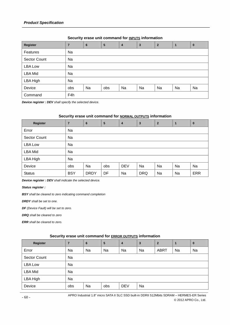
Product Specification
Security erase unit command for INPUTS information
Register 7 6 5 4 3 2 1 0
Features Na
Sector Count Na
LBA Low Na
LBA Mid Na
LBA High Na
Device obs Na obs Na Na Na Na Na
Command F4h
Device register : DEV shall specify the selected device.
Security erase unit command for NORMAL OUTPUTS information
Register 7 6 5 4 3 2 1 0
Error Na
Sector Count Na
LBA Low Na
LBA Mid Na
LBA High Na
Device obs Na obs DEV Na Na Na Na
Status BSY DRDY DF Na DRQ Na Na ERR
Device register : DEV shall indicate the selected device.
Status register :
BSY shall be cleared to zero indicating command completion
DRDY shall be set to one.
DF (Device Fault) will be set to zero.
DRQ shall be cleared to zero
ERR shall be cleared to zero.
Security erase unit command for ERROR OUTPUTS information
Register 7 6 5 4 3 2 1 0
Error Na Na Na Na Na ABRT Na Na
Sector Count Na
LBA Low Na
LBA Mid Na
LBA High Na
Device obs Na obs DEV Na
- 60 - APRO Industrial 1.8” micro SATA II SLC SSD built-in DDRII 512Mbits SDRAM – HERMES-ER Series © 2012 APRO Co., Ltd.
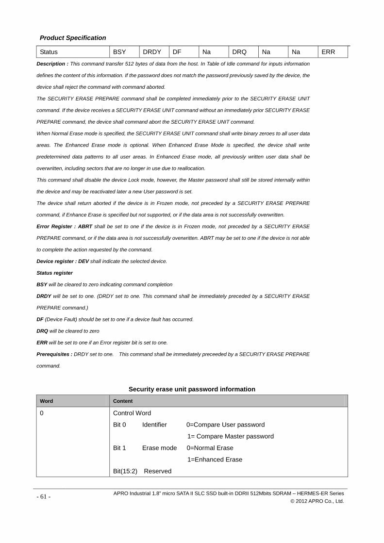
Product Specification
Status BSY DRDY DF Na DRQ Na Na ERR
Description : This command transfer 512 bytes of data from the host. In Table of Idle command for inputs information
defines the content of this information. If the password does not match the password previously saved by the device, the
device shall reject the command with command aborted.
The SECURITY ERASE PREPARE command shall be completed immediately prior to the SECURITY ERASE UNIT
command. If the device receives a SECURITY ERASE UNIT command without an immediately prior SECURITY ERASE
PREPARE command, the device shall command abort the SECURITY ERASE UNIT command.
When Normal Erase mode is specified, the SECURITY ERASE UNIT command shall write binary zeroes to all user data
areas. The Enhanced Erase mode is optional. When Enhanced Erase Mode is specified, the device shall write
predetermined data patterns to all user areas. In Enhanced Erase mode, all previously written user data shall be
overwritten, including sectors that are no longer in use due to reallocation.
This command shall disable the device Lock mode, however, the Master password shall still be stored internally within
the device and may be reactivated later a new User password is set.
The device shall return aborted if the device is in Frozen mode, not preceded by a SECURITY ERASE PREPARE
command, if Enhance Erase is specified but not supported, or if the data area is not successfully overwritten.
Error Register : ABRT shall be set to one if the device is in Frozen mode, not preceded by a SECURITY ERASE
PREPARE command, or if the data area is not successfully overwritten. ABRT may be set to one if the device is not able
to complete the action requested by the command.
Device register : DEV shall indicate the selected device.
Status register
BSY will be cleared to zero indicating command completion
DRDY will be set to one. (DRDY set to one. This command shall be immediately preceded by a SECURITY ERASE
PREPARE command.)
DF (Device Fault) should be set to one if a device fault has occurred.
DRQ will be cleared to zero
ERR will be set to one if an Error register bit is set to one.
Prerequisites : DRDY set to one. This command shall be immediately preceeded by a SECURITY ERASE PREPARE
command.
Security erase unit password information
Word Content
0 Control Word
Bit 0 Identifier 0=Compare User password
1= Compare Master password
Bit 1 Erase mode 0=Normal Erase
1=Enhanced Erase
Bit(15:2) Reserved
- 61 - APRO Industrial 1.8” micro SATA II SLC SSD built-in DDRII 512Mbits SDRAM – HERMES-ER Series © 2012 APRO Co., Ltd.
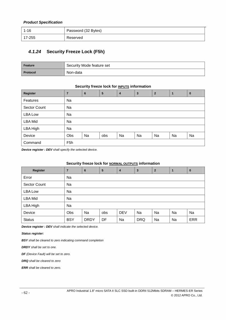
Product Specification
1-16 Password (32 Bytes)
17-255 Reserved
4.1.24 Security Freeze Lock (F5h)
Feature Security Mode feature set Protocol Non-data
Security freeze lock for INPUTS information
Register 7 6 5 4 3 2 1 0
Features Na
Sector Count Na
LBA Low Na
LBA Mid Na
LBA High Na
Device Obs Na obs Na Na Na Na Na
Command F5h
Device register : DEV shall specify the selected device.
Security freeze lock for NORMAL OUTPUTS information
Register 7 6 5 4 3 2 1 0
Error Na
Sector Count Na
LBA Low Na
LBA Mid Na
LBA High Na
Device Obs Na obs DEV Na Na Na Na
Status BSY DRDY DF Na DRQ Na Na ERR
Device register : DEV shall indicate the selected device.
Status register:
BSY shall be cleared to zero indicating command completion
DRDY shall be set to one.
DF (Device Fault) will be set to zero.
DRQ shall be cleared to zero
ERR shall be cleared to zero.
- 62 - APRO Industrial 1.8” micro SATA II SLC SSD built-in DDRII 512Mbits SDRAM – HERMES-ER Series © 2012 APRO Co., Ltd.
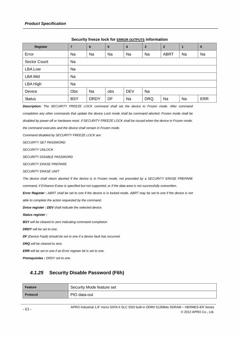
Product Specification
Security freeze lock for ERROR OUTPUTS information
Register 7 6 5 4 3 2 1 0
Error Na Na Na Na Na ABRT Na Na
Sector Count Na
LBA Low Na
LBA Mid Na
LBA High Na
Device Obs Na obs DEV Na
Status BSY DRDY DF Na DRQ Na Na ERR
Description: The SECURITY FREEZE LOCK command shall set the device to Frozen mode. After command
completion any other commands that update the device Lock mode shall be command aborted. Frozen mode shall be
disabled by power-off or hardware reset. If SECURITY FREEZE LOCK shall be issued when the device in Frozen mode,
the command executes and the device shall remain in Frozen mode.
Command disabled by SECURITY FREEZE LOCK are:
SECUIRTY SET PASSWORD
SECURITY UNLOCK
SECURITY DISABLE PASSWORD
SECURITY ERASE PREPARE
SECURITY ERASE UNIT
The device shall return aborted if the device is in Frozen mode, not preceded by a SECURITY ERASE PREPARE
command, if Enhance Erase is specified but not supported, or if the data area is not successfully overwritten.
Error Register : ABRT shall be set to one if the device is in locked mode. ABRT may be set to one if the device is not
able to complete the action requested by the command.
Dvice register : DEV shall indicate the selected device.
Status register :
BSY will be cleared to zero indicating command completion
DRDY will be set to one.
DF (Device Fault) should be set to one if a device fault has occurred.
DRQ will be cleared to zero
ERR will be set to one if an Error register bit is set to one.
Prerequisites : DRDY set to one.
4.1.25 Security Disable Password (F6h)
Feature Security Mode feature set Protocol PIO data-out
- 63 - APRO Industrial 1.8” micro SATA II SLC SSD built-in DDRII 512Mbits SDRAM – HERMES-ER Series © 2012 APRO Co., Ltd.
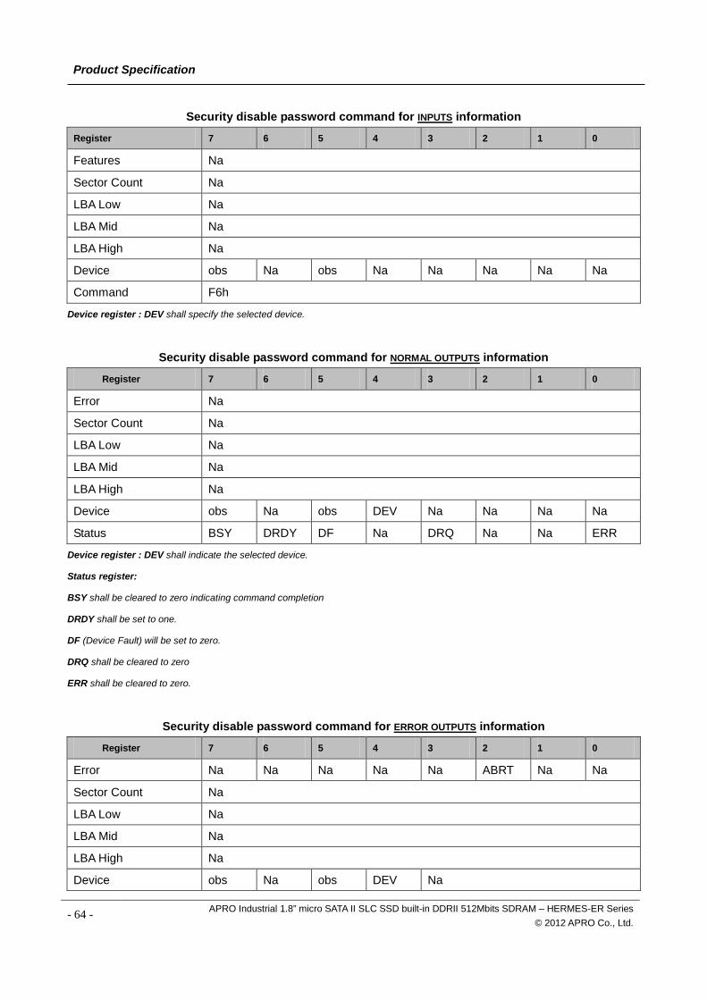
Product Specification
Security disable password command for INPUTS information
Register 7 6 5 4 3 2 1 0
Features Na
Sector Count Na
LBA Low Na
LBA Mid Na
LBA High Na
Device obs Na obs Na Na Na Na Na
Command F6h
Device register : DEV shall specify the selected device.
Security disable password command for NORMAL OUTPUTS information
Register 7 6 5 4 3 2 1 0
Error Na
Sector Count Na
LBA Low Na
LBA Mid Na
LBA High Na
Device obs Na obs DEV Na Na Na Na
Status BSY DRDY DF Na DRQ Na Na ERR
Device register : DEV shall indicate the selected device.
Status register:
BSY shall be cleared to zero indicating command completion
DRDY shall be set to one.
DF (Device Fault) will be set to zero.
DRQ shall be cleared to zero
ERR shall be cleared to zero.
Security disable password command for ERROR OUTPUTS information
Register 7 6 5 4 3 2 1 0
Error Na Na Na Na Na ABRT Na Na
Sector Count Na
LBA Low Na
LBA Mid Na
LBA High Na
Device obs Na obs DEV Na
- 64 - APRO Industrial 1.8” micro SATA II SLC SSD built-in DDRII 512Mbits SDRAM – HERMES-ER Series © 2012 APRO Co., Ltd.
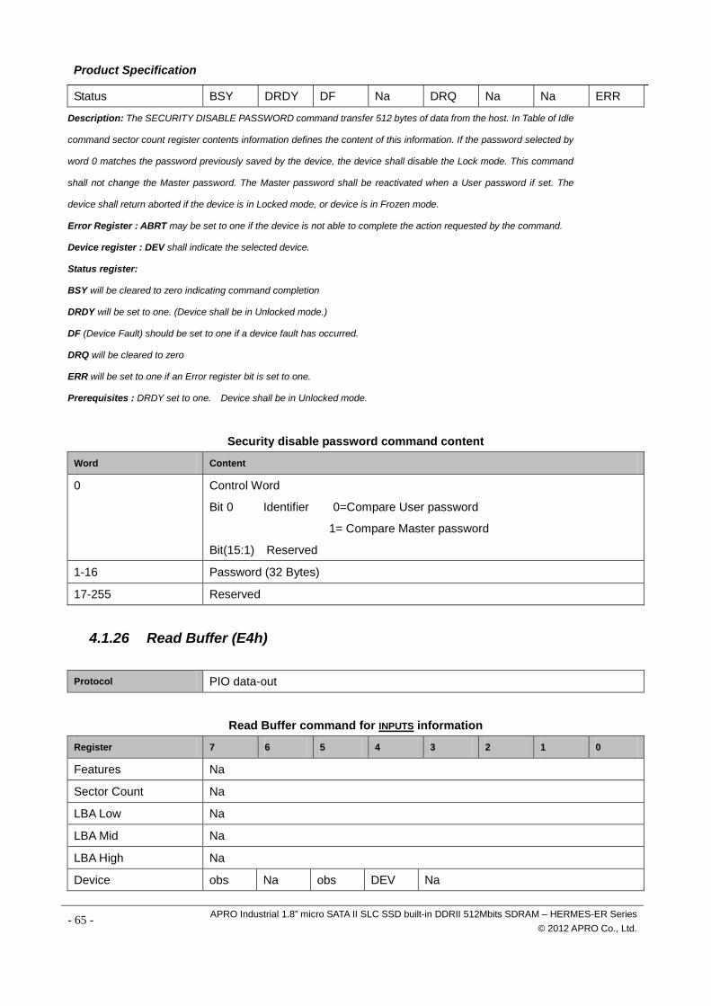
Product Specification
Status BSY DRDY DF Na DRQ Na Na ERR
Description: The SECURITY DISABLE PASSWORD command transfer 512 bytes of data from the host. In Table of Idle
command sector count register contents information defines the content of this information. If the password selected by
word 0 matches the password previously saved by the device, the device shall disable the Lock mode. This command
shall not change the Master password. The Master password shall be reactivated when a User password if set. The
device shall return aborted if the device is in Locked mode, or device is in Frozen mode.
Error Register : ABRT may be set to one if the device is not able to complete the action requested by the command.
Device register : DEV shall indicate the selected device.
Status register:
BSY will be cleared to zero indicating command completion
DRDY will be set to one. (Device shall be in Unlocked mode.)
DF (Device Fault) should be set to one if a device fault has occurred.
DRQ will be cleared to zero
ERR will be set to one if an Error register bit is set to one.
Prerequisites : DRDY set to one. Device shall be in Unlocked mode.
Security disable password command content
Word Content
0 Control Word
Bit 0 Identifier 0=Compare User password
1= Compare Master password
Bit(15:1) Reserved
1-16 Password (32 Bytes)
17-255 Reserved
4.1.26 Read Buffer (E4h)
Protocol PIO data-out
Read Buffer command for INPUTS information
Register 7 6 5 4 3 2 1 0
Features Na
Sector Count Na
LBA Low Na
LBA Mid Na
LBA High Na
Device obs Na obs DEV Na
- 65 - APRO Industrial 1.8” micro SATA II SLC SSD built-in DDRII 512Mbits SDRAM – HERMES-ER Series © 2012 APRO Co., Ltd.
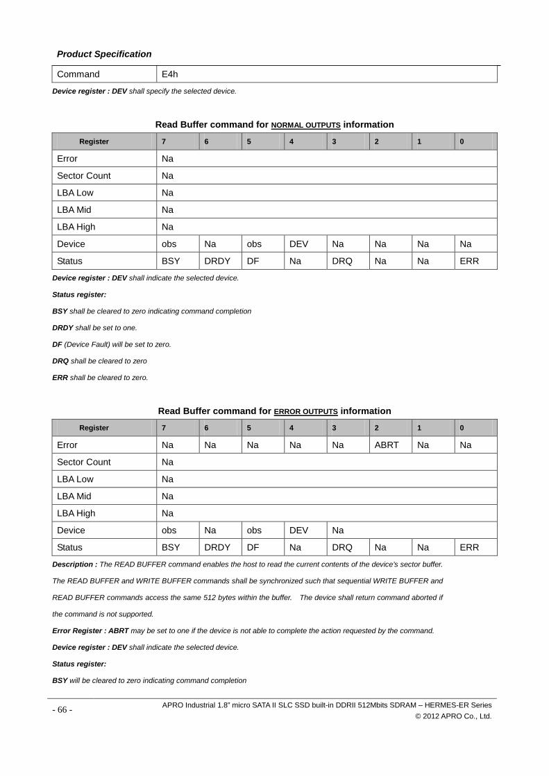
Product Specification
Command E4h
Device register : DEV shall specify the selected device.
Read Buffer command for NORMAL OUTPUTS information
Register 7 6 5 4 3 2 1 0
Error Na
Sector Count Na
LBA Low Na
LBA Mid Na
LBA High Na
Device obs Na obs DEV Na Na Na Na
Status BSY DRDY DF Na DRQ Na Na ERR
Device register : DEV shall indicate the selected device.
Status register:
BSY shall be cleared to zero indicating command completion
DRDY shall be set to one.
DF (Device Fault) will be set to zero.
DRQ shall be cleared to zero
ERR shall be cleared to zero.
Read Buffer command for ERROR OUTPUTS information
Register 7 6 5 4 3 2 1 0
Error Na Na Na Na Na ABRT Na Na
Sector Count Na
LBA Low Na
LBA Mid Na
LBA High Na
Device obs Na obs DEV Na
Status BSY DRDY DF Na DRQ Na Na ERR
Description : The READ BUFFER command enables the host to read the current contents of the device’s sector buffer.
The READ BUFFER and WRITE BUFFER commands shall be synchronized such that sequential WRITE BUFFER and
READ BUFFER commands access the same 512 bytes within the buffer. The device shall return command aborted if
the command is not supported.
Error Register : ABRT may be set to one if the device is not able to complete the action requested by the command.
Device register : DEV shall indicate the selected device.
Status register:
BSY will be cleared to zero indicating command completion
- 66 - APRO Industrial 1.8” micro SATA II SLC SSD built-in DDRII 512Mbits SDRAM – HERMES-ER Series © 2012 APRO Co., Ltd.
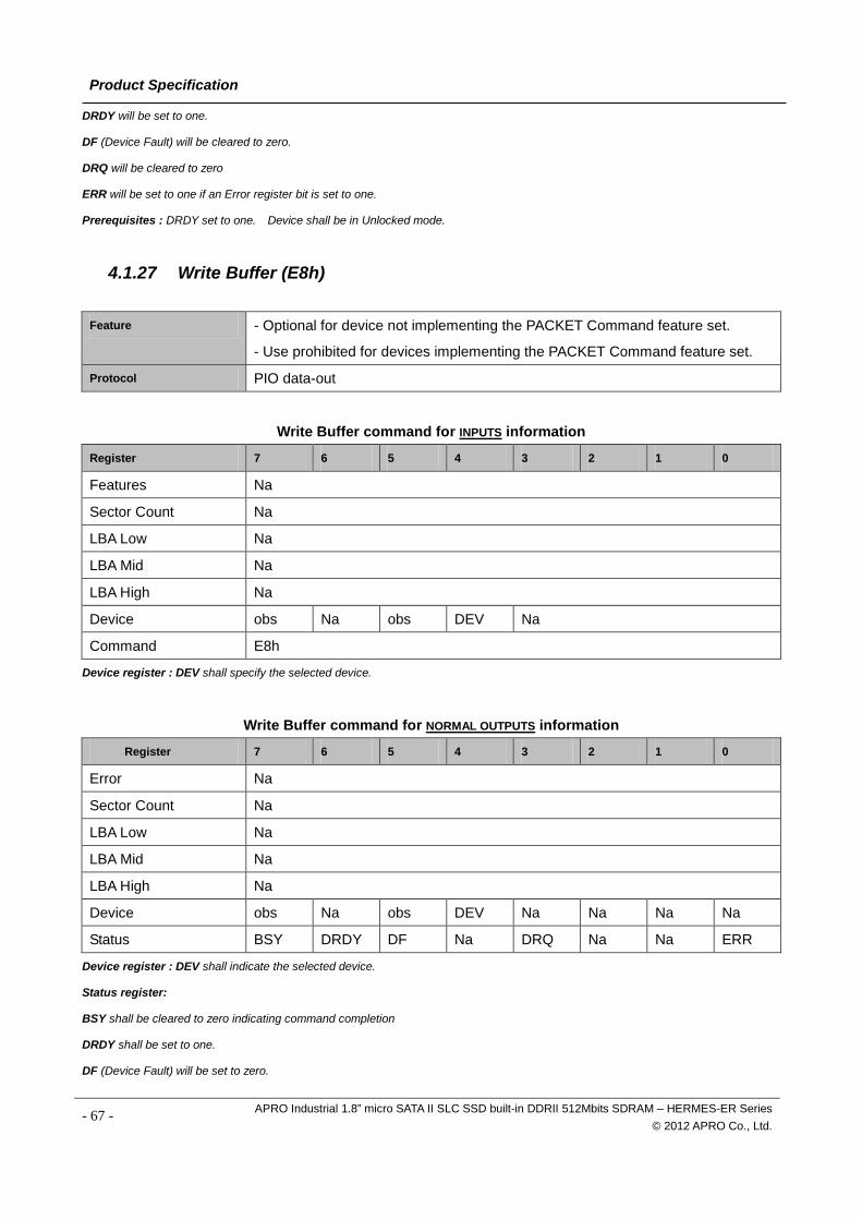
Product Specification
DRDY will be set to one.
DF (Device Fault) will be cleared to zero.
DRQ will be cleared to zero
ERR will be set to one if an Error register bit is set to one.
Prerequisites : DRDY set to one. Device shall be in Unlocked mode.
4.1.27 Write Buffer (E8h)
Feature - Optional for device not implementing the PACKET Command feature set.
- Use prohibited for devices implementing the PACKET Command feature set.
Protocol PIO data-out
Write Buffer command for INPUTS information
Register 7 6 5 4 3 2 1 0
Features Na
Sector Count Na
LBA Low Na
LBA Mid Na
LBA High Na
Device obs Na obs DEV Na
Command E8h
Device register : DEV shall specify the selected device.
Write Buffer command for NORMAL OUTPUTS information
Register 7 6 5 4 3 2 1 0
Error Na
Sector Count Na
LBA Low Na
LBA Mid Na
LBA High Na
Device obs Na obs DEV Na Na Na Na
Status BSY DRDY DF Na DRQ Na Na ERR
Device register : DEV shall indicate the selected device.
Status register:
BSY shall be cleared to zero indicating command completion
DRDY shall be set to one.
DF (Device Fault) will be set to zero.
- 67 - APRO Industrial 1.8” micro SATA II SLC SSD built-in DDRII 512Mbits SDRAM – HERMES-ER Series © 2012 APRO Co., Ltd.
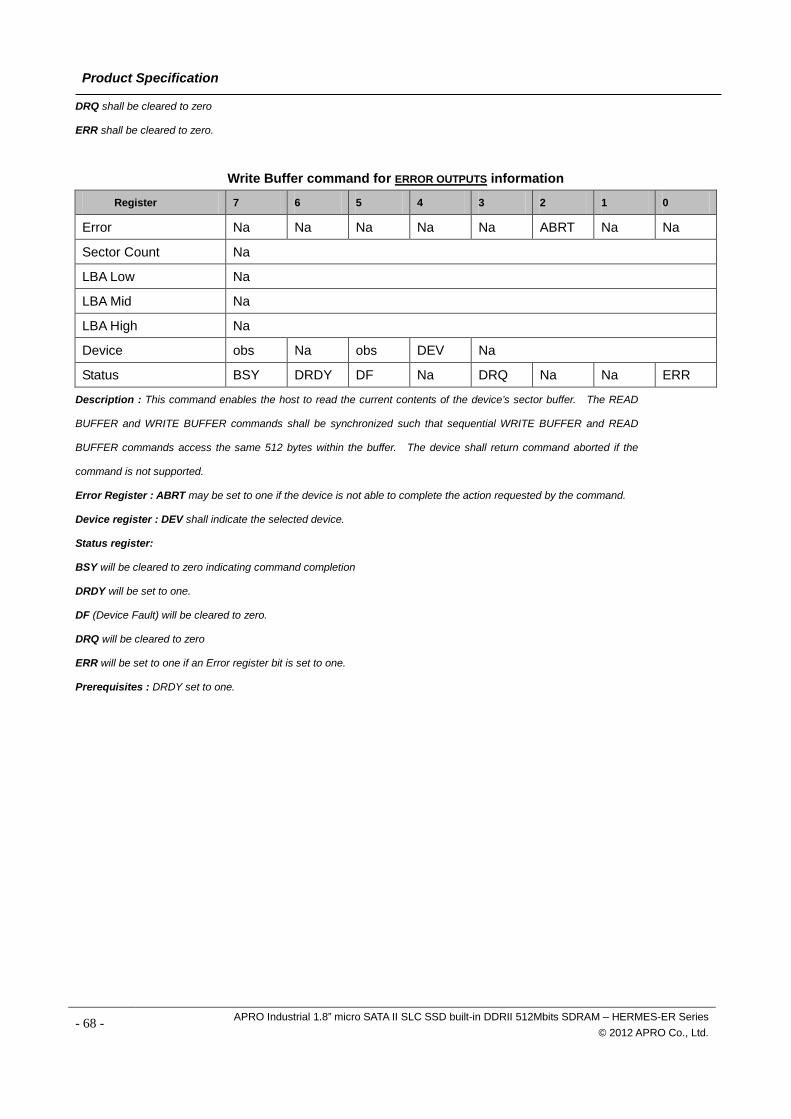
Product Specification
DRQ shall be cleared to zero
ERR shall be cleared to zero.
Write Buffer command for ERROR OUTPUTS information
Register 7 6 5 4 3 2 1 0
Error Na Na Na Na Na ABRT Na Na
Sector Count Na
LBA Low Na
LBA Mid Na
LBA High Na
Device obs Na obs DEV Na
Status BSY DRDY DF Na DRQ Na Na ERR
Description : This command enables the host to read the current contents of the device’s sector buffer. The READ
BUFFER and WRITE BUFFER commands shall be synchronized such that sequential WRITE BUFFER and READ
BUFFER commands access the same 512 bytes within the buffer. The device shall return command aborted if the
command is not supported.
Error Register : ABRT may be set to one if the device is not able to complete the action requested by the command.
Device register : DEV shall indicate the selected device.
Status register:
BSY will be cleared to zero indicating command completion
DRDY will be set to one.
DF (Device Fault) will be cleared to zero.
DRQ will be cleared to zero
ERR will be set to one if an Error register bit is set to one.
Prerequisites : DRDY set to one.
- 68 - APRO Industrial 1.8” micro SATA II SLC SSD built-in DDRII 512Mbits SDRAM – HERMES-ER Series © 2012 APRO Co., Ltd.
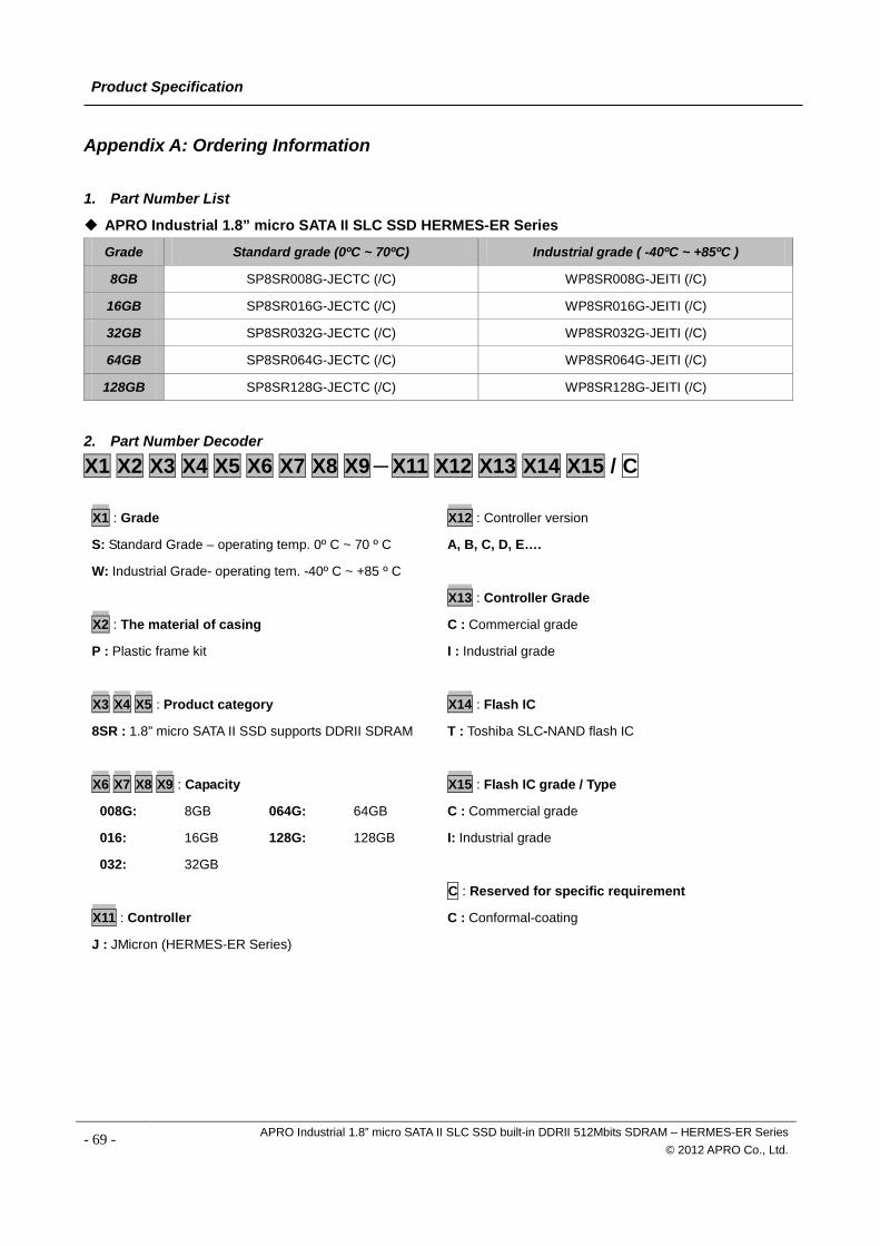
Product Specification
Appendix A: Ordering Information
1. Part Number List
APRO Industrial 1.8” micro SATA II SLC SSD HERMES-ER Series
Grade Standard grade (0ºC ~ 70ºC) Industrial grade ( -40ºC ~ +85ºC )
8GB SP8SR008G-JECTC (/C) WP8SR008G-JEITI (/C)
16GB SP8SR016G-JECTC (/C) WP8SR016G-JEITI (/C)
32GB SP8SR032G-JECTC (/C) WP8SR032G-JEITI (/C)
64GB SP8SR064G-JECTC (/C) WP8SR064G-JEITI (/C)
128GB SP8SR128G-JECTC (/C) WP8SR128G-JEITI (/C)
2. Part Number Decoder
X1 X2 X3 X4 X5 X6 X7 X8 X9-X11 X12 X13 X14 X15 / C
X1 : Grade
S: Standard Grade – operating temp. 0º C ~ 70 º C
W: Industrial Grade- operating tem. -40º C ~ +85 º C
X2 : The material of casing
P : Plastic frame kit
X3 X4 X5 : Product category
8SR : 1.8” micro SATA II SSD supports DDRII SDRAM
X6 X7 X8 X9 : Capacity
008G: 8GB 064G: 64GB
016: 16GB 128G: 128GB
032: 32GB
X11 : Controller
J : JMicron (HERMES-ER Series)
X12 : Controller version
A, B, C, D, E….
X13 : Controller Grade
C : Commercial grade
I : Industrial grade
X14 : Flash IC
T : Toshiba SLC-NAND flash IC
X15 : Flash IC grade / Type
C : Commercial grade
I: Industrial grade
C : Reserved for specific requirement
C : Conformal-coating
- 69 - APRO Industrial 1.8” micro SATA II SLC SSD built-in DDRII 512Mbits SDRAM – HERMES-ER Series © 2012 APRO Co., Ltd.
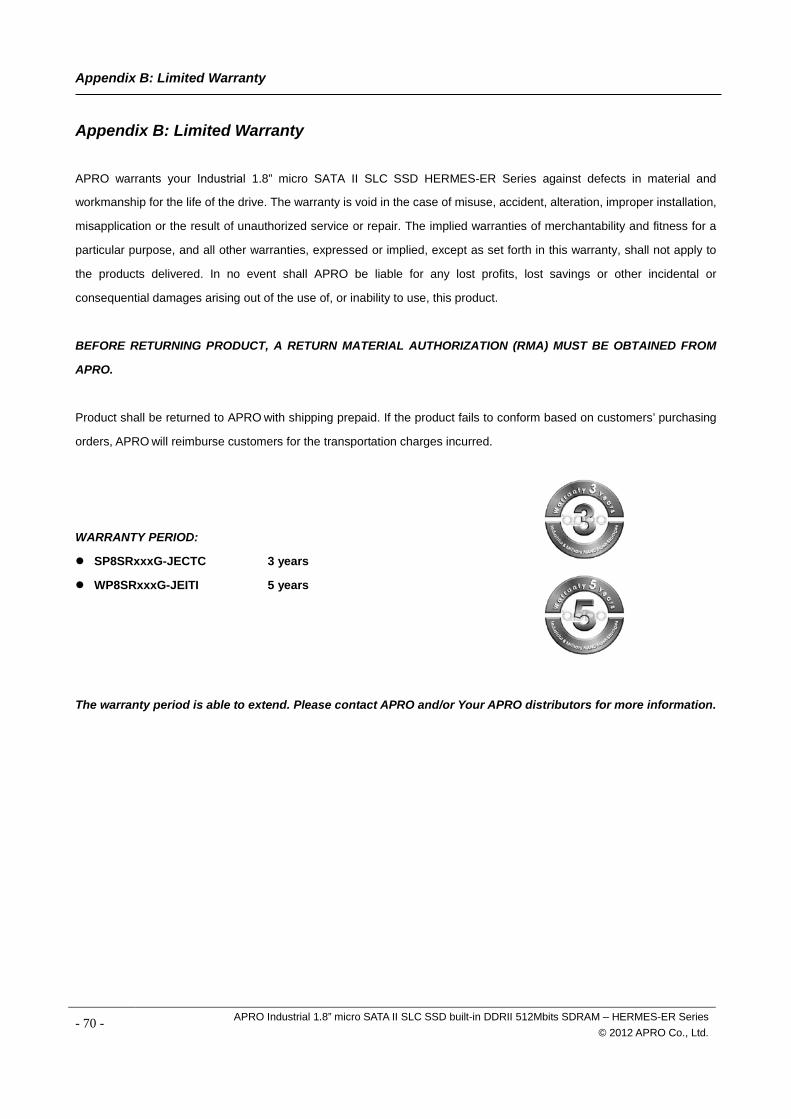
Appendix B: Limited Warranty
Appendix B: Limited Warranty APRO warrants your Industrial 1.8” micro SATA II SLC SSD HERMES-ER Series against defects in material and
workmanship for the life of the drive. The warranty is void in the case of misuse, accident, alteration, improper installation,
misapplication or the result of unauthorized service or repair. The implied warranties of merchantability and fitness for a
particular purpose, and all other warranties, expressed or implied, except as set forth in this warranty, shall not apply to
the products delivered. In no event shall APRO be liable for any lost profits, lost savings or other incidental or
consequential damages arising out of the use of, or inability to use, this product.
BEFORE RETURNING PRODUCT, A RETURN MATERIAL AUTHORIZATION (RMA) MUST BE OBTAINED FROM
APRO.
Product shall be returned to APRO with shipping prepaid. If the product fails to conform based on customers’ purchasing
orders, APRO will reimburse customers for the transportation charges incurred.
WARRANTY PERIOD:
SP8SRxxxG-JECTC 3 years
WP8SRxxxG-JEITI 5 years
The warranty period is able to extend. Please contact APRO and/or Your APRO distributors for more information.
- 70 - APRO Industrial 1.8” micro SATA II SLC SSD built-in DDRII 512Mbits SDRAM – HERMES-ER Series © 2012 APRO Co., Ltd.


