Bulletin 825-P Modular Protection System Bulletin 825-P «$FXUUHQWUDQJH 120/240V AC and 24/48V DC Control Power Suitable for low- and medium-voltage applications Modular design with pluggable options Voltage input card Expansion I/O cards Communications cards, including DeviceNet RTD scanner module Conformal Coating options Energy Metering MWh MVARh Comprehensive protection functions Built-in keypad and backlit 2-line LCD Test/Reset button Status LEDs Front accessible RS232 port Three output relays Two configurable inputs NEMA 12 (IP65) compatible Standards Compliance IEC 60947-1 IEC 60947-4 Type 2 Coordination CSA C22.2, No. 14 UL 508 Certifications UL Listed (File No. E 14840, Guide NKCR) CSA Certified (File No. LR1234) CE C-tick Product Overview Description The Bulletin 825-P Modular Protection System for motors offers a compact, modular design that uniquely allows an installer to configure a device’s functional capabilities to match the application requirements. Flexibility is also afforded by accommodating future expansion of the system as the application requirements grow. Finally, ease of installation is provided through pluggable options and accessories. Comprehensive Protection The Bulletin 825-P Modular Protection System offers in-depth motor protection coverage by monitoring the critical elements of motor current, line voltage and temperature. High resolution settings allow the installer to configure a precise envelope of protection to achieve maximum motor utilization while avoiding damage and downtime.
Transcript
Bulletin 825-P Modular Protection System
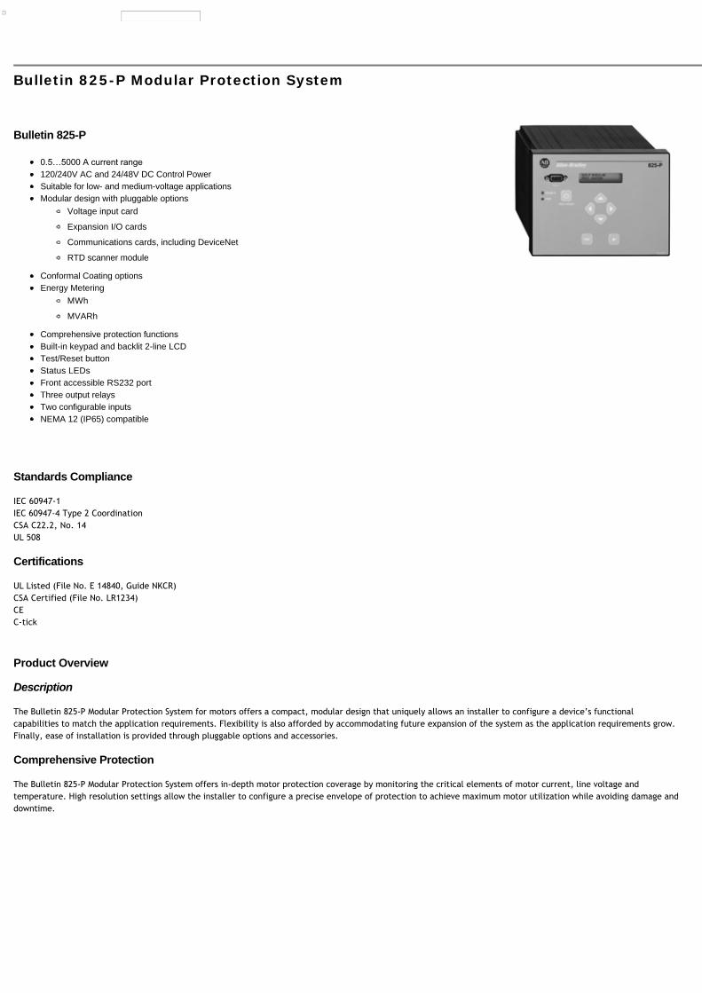
Bulletin 825-P
120/240V AC and 24/48V DC Control PowerSuitable for low- and medium-voltage applicationsModular design with pluggable options
IEC 60947-1IEC 60947-4 Type 2 CoordinationCSA C22.2, No. 14UL 508
Certifications
UL Listed (File No. E 14840, Guide NKCR)CSA Certified (File No. LR1234)CEC-tick
Product Overview
Description
The Bulletin 825-P Modular Protection System for motors offers a compact, modular design that uniquely allows an installer to configure a device’s functionalcapabilities to match the application requirements. Flexibility is also afforded by accommodating future expansion of the system as the application requirements grow.Finally, ease of installation is provided through pluggable options and accessories.
Comprehensive Protection
The Bulletin 825-P Modular Protection System offers in-depth motor protection coverage by monitoring the critical elements of motor current, line voltage andtemperature. High resolution settings allow the installer to configure a precise envelope of protection to achieve maximum motor utilization while avoiding damage anddowntime.
ANSII No. Function ANSII No. Function
Current Elements Temperature Elements
51 Thermal Overload 49 PTC Thermistor
46 Current Imbalance/Phase Loss 49 Stator RTD
50G/51G Ground Fault 38 Bearing RTD
37 Undercurrent (Load Loss) — Ambient and Other RTD
48 Overcurrent (Load Jam) Power Elements
50 Short Circuit 37 Underpower
47 Phase Reversal 55/78 Power Factor
81 Frequency — Reactive Power
86 Overload Lockout — —
Voltage Elements Motor Starting Elements
27 Undervoltage 66 Starts/Hour
59 Overvoltage — Stall - Acceleration Time Monitoring
47 Phase Reversal 14 Speed Switch Monitoring
81 Frequency 19 Reduced Voltage Starting
— — 48 Incomplete Start
NOTE: Voltage, power, and energy elements are only available with the installation of the voltage input option card.
Full Function Metering
Current Elements Voltage Elements Power Elements Energy Elements Thermal Elements
Phase Currents Line-Line Voltages Real Power (kW) Real Energy (MWh) % Thermal Capacity Utilization
Average Current Avg. Line-Line Voltage Reactive Power (kVAR) Reactive Energy Forward (MVARh) RTD Values
% Motor Load Line-Neutral Voltages Apparent Power (kVA) Reactive Energy Reverse (MVARh) —
Current Imbalance Avg. Line-Neutral Voltage Power Factor Apparent Energy (MVAh) —
Ground Fault Current Voltage Imbalance — — —
System Frequency System Frequency — — —
NOTE: Voltage and power elements are only available with the installation of the voltage input option card.
Statistical Values
The 825-P Modular Protection System provides the following valuable statistical values of motor operation:
Elapsed time of operation
Stopped time
Percent of time running
Number of starts
Number of emergency starts
Date and time of last trip reset
Historical Data
The 825-P Modular Protection System saves records for the five most recent trip events. Each trip event is summarized with record of the following prior to trip datacapture:
Event day and time
Trip identification
Phase and ground current values
Voltage values
Function Overview
Description Trip Level Setting Range Trip Delay Setting Time Warning Level Setting Range
Motor FLA Ie 0.5…5000 A — —
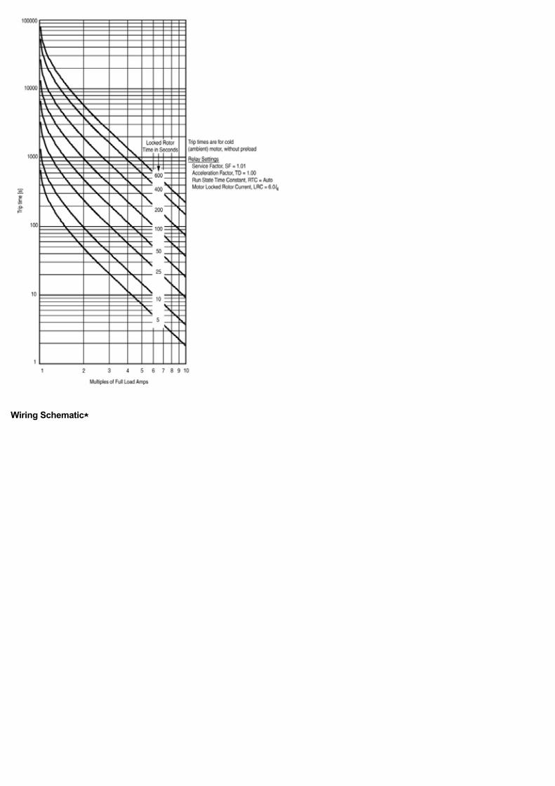
Locked Rotor Current 2.5…12 x Ie — 50…100% TCU
Locked Rotor Time 1…600 s — —
Short Circuit 4…12 x Ie 0…5.00 s 4…12 x Ie
Ground Fault (Residual) 0.1…1.0 x Ie 0…5.00 s 0.1…1.0 x Ie
Ground Fault (Core balance) 0.01…25 A 0…5.00 s 0.01…25 A
Jam 1.0…6.0 x Ie 0…5.00 s 1.0…6.0 x Ie
Undercurrent 0.1…1.0 x Ie 0…120 s 0.1…1.0 x Ie
Current Imbalance 5…80% 0…240 s 5…80%
Start Monitoring — 0…240 s —
RTD Temp 0…250 °C — 0…250 °C
Phase Reversal Disable, Enable — —
Undervoltage 0.60…1.00 x Vnom 0…120 s 0.60…1.00 x Vnom
Overvoltage 1.00…1.20 x Vnom 0…120 s 1.00…1.20 x Vnom
Underpower 1…25000 kW 0…240 s 1…25000 kW
Power Factor 0.05…0.99 0…240 s 0.05…0.99
VAR 1…25000 kVAR 0…240 s 1…25000 kVAR
Frequency 45…55/55…65 Hz 0…240 s 45…55/55…65 Hz
Start Inhibit (Starts/hour) 1…15 — —
Speed Switch — 0…240 s —
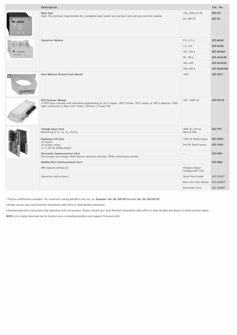
Description Cat. No.
Basic UnitNote: The minimum requirements for a complete basic system are one basic unit and one converter module.
120…240V AC/DC 825-PD⋆
24…48V DC 825-PZ⋆
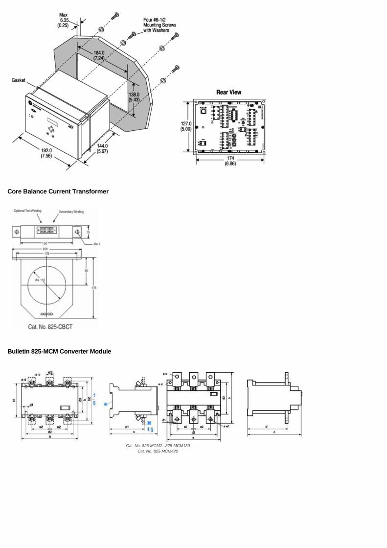
Converter Module 0.5…2.5 A 825-MCM2
1.0…5.0 825-MCM5
181…520 A 825-MCM20
30…180 A 825-MCM180
160…420 825-MCM420
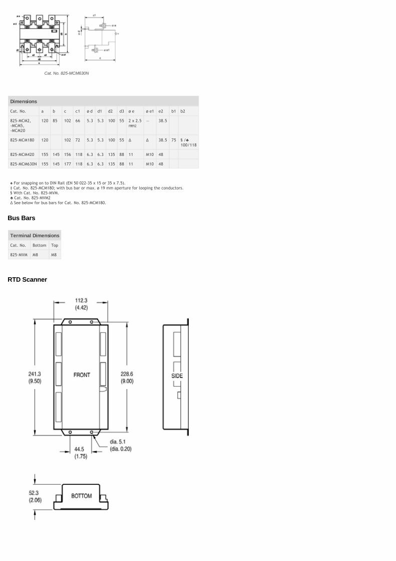
160…630 A 825-MCM630N
Core Balance Ground Fault Sensor 100:1 825-CBCT
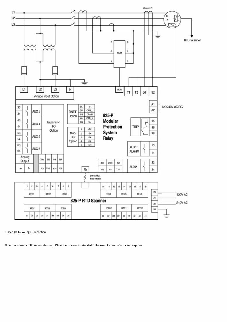
RTD Scanner Module12 RTD input channels with individual programming for 10 copper, 100 nickel, 120 nickel, or 100 platinum. Fiberoptic connection to Basic Unit. Class I, Division 2, Group T48.
120 / 240V AC 825-PR12D
Voltage Input CardMonitoring of VA, VB, VC, and VN
300V AC Line toNeutral Max.
825-PVS⋆
Expansion I/O Card(3) Inputs(4) Output relays(1) 4…20 mA analog output
⋆ Factory modification available. For conformal coating add CC to the cat. no. Example: Cat. No. 825-PZ becomes Cat. No. 825-PZ-CC.
§ Please contact your local Rockwell Automation sales office or Allen-Bradley distributor.
‡ Detailed operation instructions ship separately from the product. Please contact your local Rockwell Automation sales office or Allen-Bradley distributor to obtain printed copies.
NOTE: A no-charge download can be found at www.rockwellautomation.com/support/firmware.html.
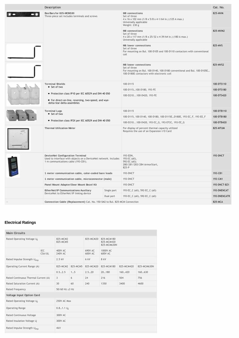
Description Cat. No.
Bus Bars for 825-MCM180Three-piece set includes terminals and screws
M8 connectionsSet of three4 x 16 x 102 mm (1/8 x 5/8 x 4-1/64 in.) (125 A max.)Universally applicableWeight: 230 g
825-MVM
M8 connectionsSet of three4 x 20 x 117 mm (1/8 x 25/32 x 4-39/64 in.) (180 A max.)Universally applicable
825-MVM2
M6 lower connectionsSet of threeFor mounting on Bul. 100-D105 and 100-D110 contactors with conventionalcoil
825-MVS
M8 lower connectionsSet of threeFor mounting on Bul. 100-D140, 100-D180 conventional and Bul. 100-D105E…100-D180E contactors with electronic coil
825-MVS2
Terminal ShieldsSet of two
Protection class IP10 per IEC 60529 and DIN 40 050
For direct-on-line, reversing, two-speed, and wye-delta/star-delta assemblies
100-D115 100-DTS110
100-D115…100-D180, 193-FE 100-DTS180
100-D210...100-D420, 193-FE 100-DTS420
Terminal LugsSet of two
Protection class IP2X per IEC 60529 and DIN 40 050
For snapping on to DIN Rail (EN 50 022-35 x 15 or 35 x 7.5).‡ Cat. No. 825-MCM180; with bus bar or max. ø 19 mm aperture for looping the conductors.§ With Cat. No. 825-MVM.
Cat. No. 825-MVM2∆ See below for bus bars for Cat. No. 825-MCM180.


![mathcal P$-adic modular forms over Shimura curves over ... · Riemann zeta function. Serre [Ser73]definedp-adic modular forms as p-adic limits of q-expansions of classical modular](https://static.documents.pub/doc/80x56/5f1055f77e708231d4489a88/mathcal-p-adic-modular-forms-over-shimura-curves-over-riemann-zeta-function.jpg)


