Industrial Control Transformers 66 Industrial control transformers are used to reduce supply voltages to 230 V or lower for the operation of electromagnetic devices such as contactors, solenoids, relays, and timers. They are especially designed to accommodate the momentary current inrush caused when electromagnetic components are energized . . . without sacrificing secondar y voltage stability beyond practical limits. Acme Industrial Control Transformers are dry-type, step -down transformers with the secondary control circuit isolated from the primary line circuit to assure maximum safety. Voltage regulation of Acme Industrial Control Transformers exceeds standards recommended by the National Electrical Manufacturers Association. Secondary circuit voltage drop between no-load and momentary overload remains exceptionally low. This excellent secondary circuit voltage regulation assures reliable operation of electromagnetic components and may permit the use of a smaller and less expensive industrial control transformer. Acme Industrial Control Transformers Meet or Exceed UL, CSA, NEMA and ANSI Acme Industrial Control Transformers 50 through 5000 VA are UL Listed, File E79947 and CSA certified, File 7357. Laminations — High-permeability silicon steel continuously annealed to minimize core losses. Magnet Wire — Copper magnet wire is coated with high temperature-resisting insulating film. Coils — Precision wound by machine; total turns per coil automatically counted. Terminals — Copper-alloy terminals are soldered to coil leads. “Quick Connects” are available on 50-150 VA units. Mounting — Heavy steel mounting plates add strength to core construction and provide firm mounting, slotted to facilitate installation. Terminal Boards — Sturdy phenolic terminal boards. Integrally Mounted Fuse Blocks Sizing Primary Fuses: Primary Amps< 2, fuse size is 300% of rated primary current. Primary Amps 2< 9, fuse size is 167% of rated primary current. Primary Amps ≥ 9, fuse size is 125% of rated primary current. Sizing Secondary Fuses: Secondary Amps < 9, fuse size is 167% of rated secondary current. Secondary Amps ≥ 9, fuse size is 125% of rated secondary current. EPOXETRAN ™ Encapsulated Control Transformers. See Pages 78- 79 in this section. Primary Fuse Kit with Snap-on Secondary Fuse Block Jumper Link Connections Secondary Fuse Clips SECTION V INDUSTRIAL CONTROL TRANSFORMERS
Transcript
Industrial Control Transformers
66
Industrial control transformers are used toreduce supply voltages to 230 V or lowerfor the operation of electromagnetic devicessuch as contactors, solenoids, relays, andtimers. They are especially designed toaccommodate the momentary currentinrush caused when electromagneticcomponents are energized . . . withoutsacrificing secondary voltage stabilitybeyond practical limits.
Acme Industrial Control Transformersare dry-type, step-down transformerswith the secondary control circuit isolatedfrom the primary line circuit to assuremaximum safety.
Voltage regulation of Acme IndustrialControl Transformers exceeds standardsrecommended by the National ElectricalManufacturers Association. Secondarycircuit voltage drop between no-load andmomentary overload remains exceptionallylow. This excellent secondary circuit voltageregulation assures reliable operation ofelectromagnetic components and maypermit the use of a smaller and lessexpensive industrial control transformer.
Acme Industrial ControlTransformers Meet or Exceed UL,CSA, NEMA and ANSIAcme Industrial Control Transformers 50 through 5000 VA are UL Listed, FileE79947 and CSA certified, File 7357.
Magnet Wire — Copper magnet wireis coated with high temperature-resistinginsulating film.
Coils — Precision wound by machine;total turns per coil automatically counted.
Terminals — Copper-alloy terminals aresoldered to coil leads. “Quick Connects”are available on 50-150 VA units.
Mounting — Heavy steel mountingplates add strength to core constructionand provide firm mounting, slotted tofacilitate installation.
Terminal Boards — Sturdy phenolicterminal boards.
Integrally Mounted Fuse Blocks
Sizing Primary Fuses:Primary Amps<2, fuse size is 300%
of rated primary current.Primary Amps 2<9, fuse size is
167% of rated primary current.Primary Amps ≥9, fuse size is
125% of rated primary current.
Sizing Secondary Fuses:Secondary Amps <9, fuse size is
167% of rated secondary current.Secondary Amps ≥9, fuse size is
125% of rated secondary current.
EPOXETRAN™ Encapsulated Control Transformers. See Pages 78-79 in this section.
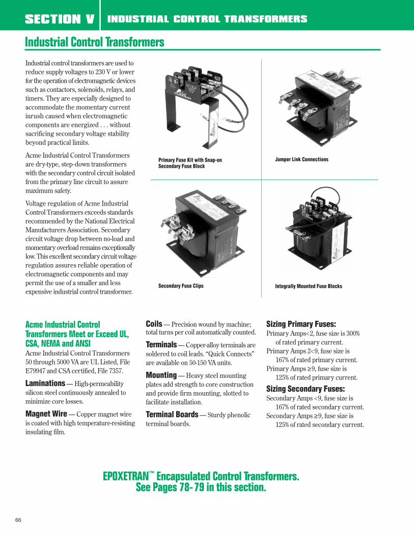
Primary Fuse Kit with Snap-onSecondary Fuse Block
Jumper Link Connections
Secondary Fuse Clips
SECTION V INDUSTRIAL CONTROL TRANSFORMERS
67
To make the proper transformer selection,the load must be completely analyzed . . .which involves every electrically energizedcomponent in the control circuit.
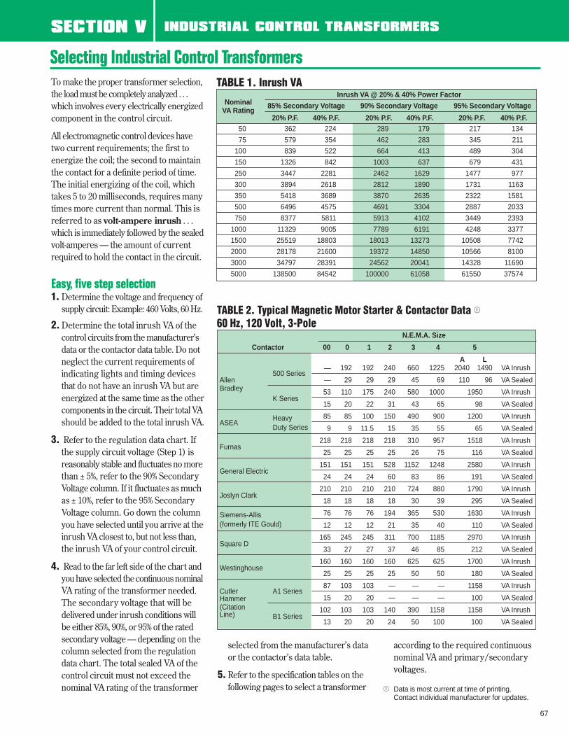
All electromagnetic control devices havetwo current requirements; the first toenergize the coil; the second to maintainthe contact for a definite period of time.The initial energizing of the coil, whichtakes 5 to 20 milliseconds, requires manytimes more current than normal. This isreferred to as volt-ampere inrush . . .which is immediately followed by the sealedvolt-amperes — the amount of currentrequired to hold the contact in the circuit.
Easy, five step selection1. Determine the voltage and frequency of
supply circuit: Example: 460 Volts, 60 Hz.
2. Determine the total inrush VA of thecontrol circuits from the manufacturer’sdata or the contactor data table. Do notneglect the current requirements of indicating lights and timing devicesthat do not have an inrush VA but are energized at the same time as the othercomponents in the circuit. Their total VAshould be added to the total inrush VA.
3. Refer to the regulation data chart. If the supply circuit voltage (Step 1) is reasonably stable and fluctuates no morethan ± 5%, refer to the 90% Secondary Voltage column. If it fluctuates as muchas ± 10%, refer to the 95% Secondary Voltage column. Go down the column you have selected until you arrive at theinrush VA closest to, but not less than,the inrush VA of your control circuit.
4. Read to the far left side of the chart and you have selected the continuous nominal VA rating of the transformer needed. The secondary voltage that will bedelivered under inrush conditions will be either 85%, 90%, or 95% of the ratedsecondary voltage — depending on the column selected from the regulation data chart. The total sealed VA of the control circuit must not exceed the nominal VA rating of the transformer
selected from the manufacturer’s dataor the contactor’s data table.
5. Refer to the specification tables on the following pages to select a transformer
according to the required continuous nominal VA and primary/secondary voltages.
1 Data is most current at time of printing. Contact individual manufacturer for updates.
TABLE 2. Typical Magnetic Motor Starter & Contactor Data 1
60 Hz, 120 Volt, 3-Pole
Selecting Industrial Control Transformers
Inrush VA @ 20% & 40% Power FactorNominal 85% Secondary Voltage 90% Secondary Voltage 95% Secondary Voltage
VA Rating20% P.F. 40% P.F. 20% P.F. 40% P.F. 20% P.F. 40% P.F.
160 160 160 160 625 625 1700 VA InrushWestinghouse
25 25 25 25 50 50 180 VA Sealed
Cutler A1 Series87 103 103 — — — 1158 VA Inrush
Hammer 15 20 20 — — — 100 VA Sealed(Citation 102 103 103 140 390 1158 1158 VA InrushLine) B1 Series
13 20 20 24 50 100 100 VA Sealed
SECTION V INDUSTRIAL CONTROL TRANSFORMERS
TABLE 1. Inrush VA
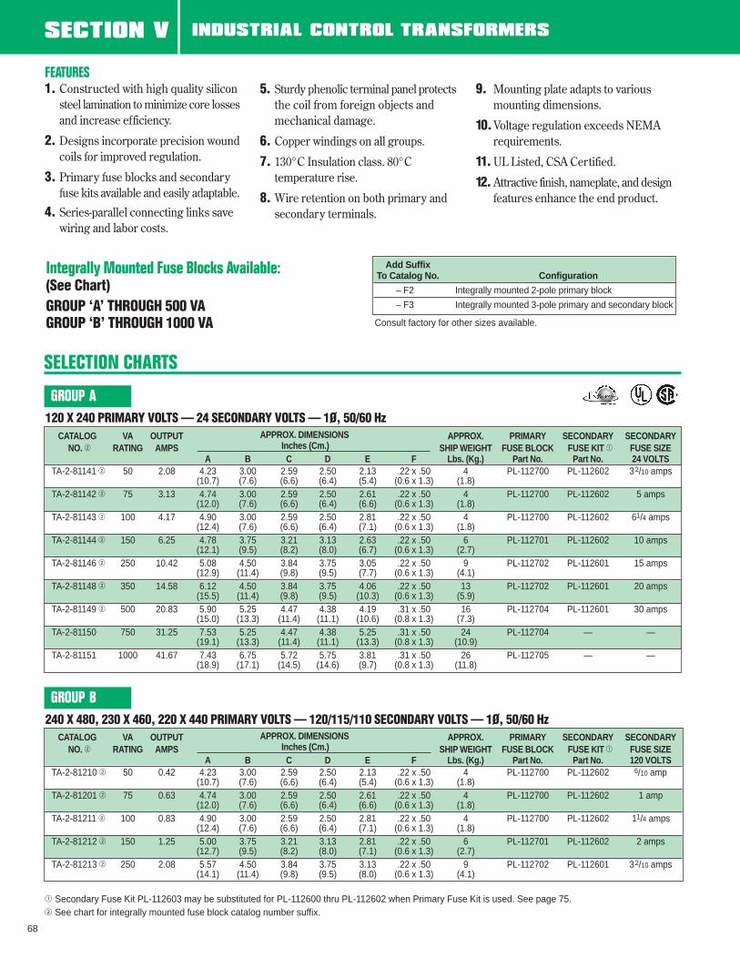
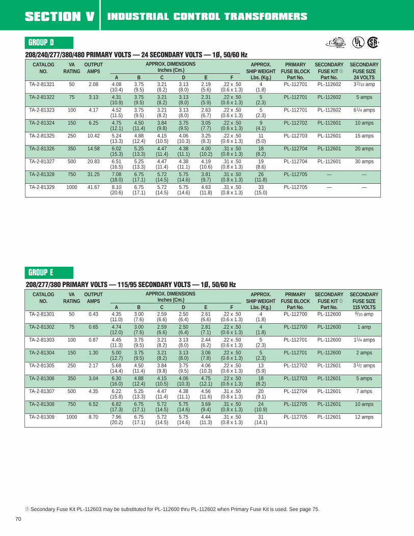
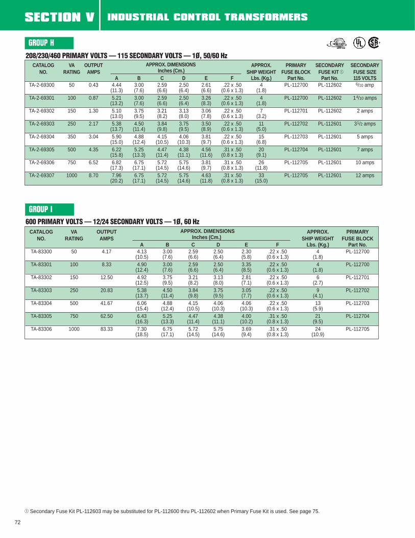
1 Secondary Fuse Kit PL-112603 may be substituted for PL-112600 thru PL-112602 when Primary Fuse Kit is used. See page 75.2 See chart for integrally mounted fuse block catalog number suffix.
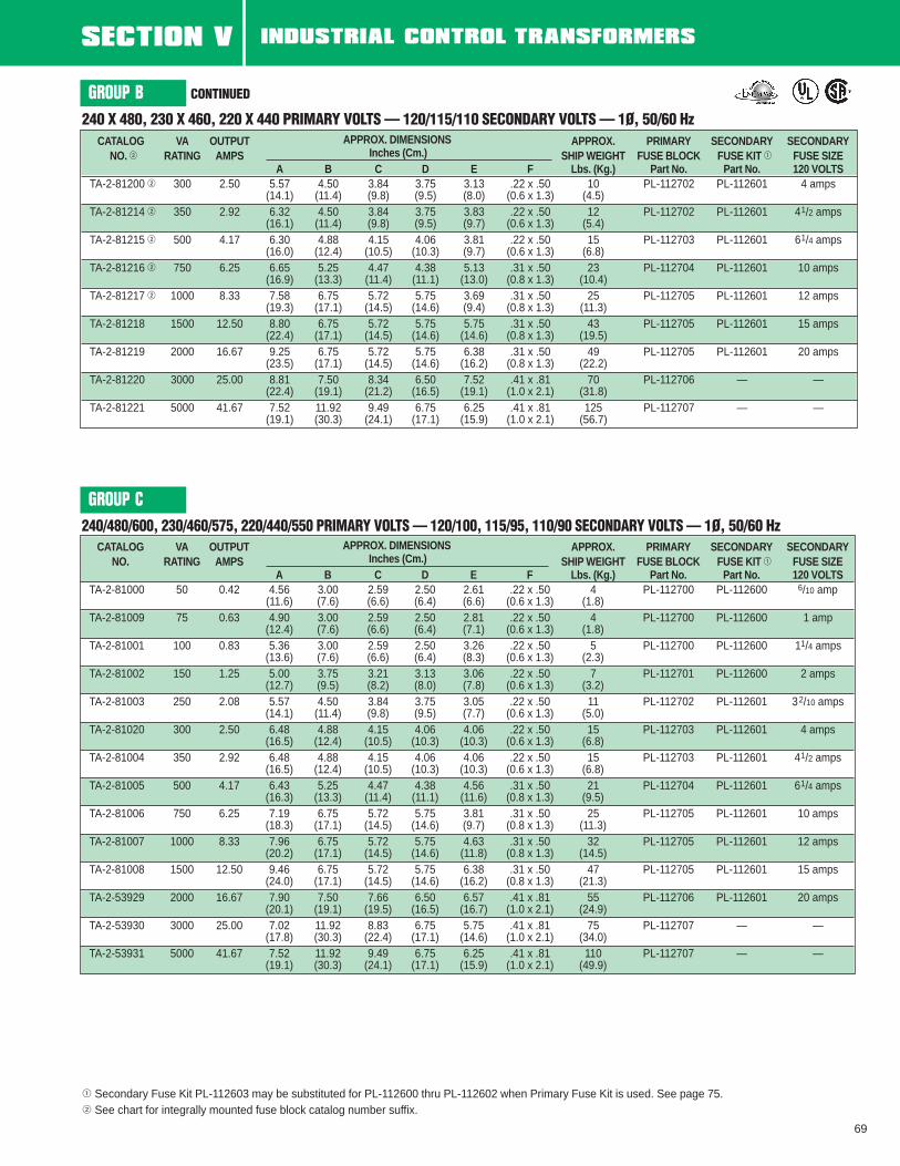
1 Secondary Fuse Kit PL-112603 may be substituted for PL-112600 thru PL-112602 when Primary Fuse Kit is used. See page 75.2 See chart for integrally mounted fuse block catalog number suffix.
240 X 480, 230 X 460, 220 X 440 PRIMARY VOLTS — 120/115/110 SECONDARY VOLTS — 1Ø, 50/60 Hz
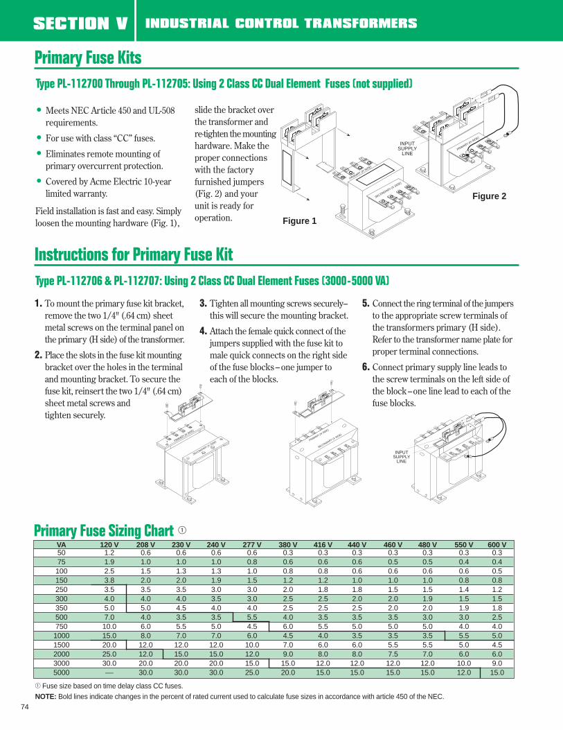
• Covered by Acme Electric 10-year limited warranty.
Field installation is fast and easy. Simplyloosen the mounting hardware (Fig. 1),
slide the bracket overthe transformer andre-tighten the mountinghardware. Make theproper connectionswith the factory furnished jumpers(Fig. 2) and your unit is ready foroperation.
1. To mount the primary fuse kit bracket,remove the two 1/4" (.64 cm) sheet metal screws on the terminal panel onthe primary (H side) of the transformer.
2. Place the slots in the fuse kit mountingbracket over the holes in the terminal and mounting bracket. To secure the fuse kit, reinsert the two 1/4" (.64 cm) sheet metal screws and tighten securely.
3. Tighten all mounting screws securely–this will secure the mounting bracket.
4. Attach the female quick connect of the jumpers supplied with the fuse kit to male quick connects on the right side of the fuse blocks – one jumper to each of the blocks.
5. Connect the ring terminal of the jumpersto the appropriate screw terminals of the transformers primary (H side). Refer to the transformer name plate forproper terminal connections.
6. Connect primary supply line leads to the screw terminals on the left side of the block –one line lead to each of the fuse blocks.
Primary Fuse Kits
Instructions for Primary Fuse KitType PL-112706 & PL-112707: Using 2 Class CC Dual Element Fuses (3000-5000 VA)
Type PL-112700 Through PL-112705: Using 2 Class CC Dual Element Fuses (not supplied)
PRIMARY (H SIDE)
SECONDARY (X SIDE)
PRIMARY (H SIDE)
INPUTSUPPLY
LINE
PRIMARY (H SIDE)
SECONDARY (X SIDE) PRIMARY (H
SIDE)
SECONDARY (X SIDE)
INPUTSUPPLY
LINE
Figure 1
Figure 2
Primary Fuse Sizing Chart 1
1 Fuse size based on time delay class CC fuses.NOTE: Bold lines indicate changes in the percent of rated current used to calculate fuse sizes in accordance with article 450 of the NEC.
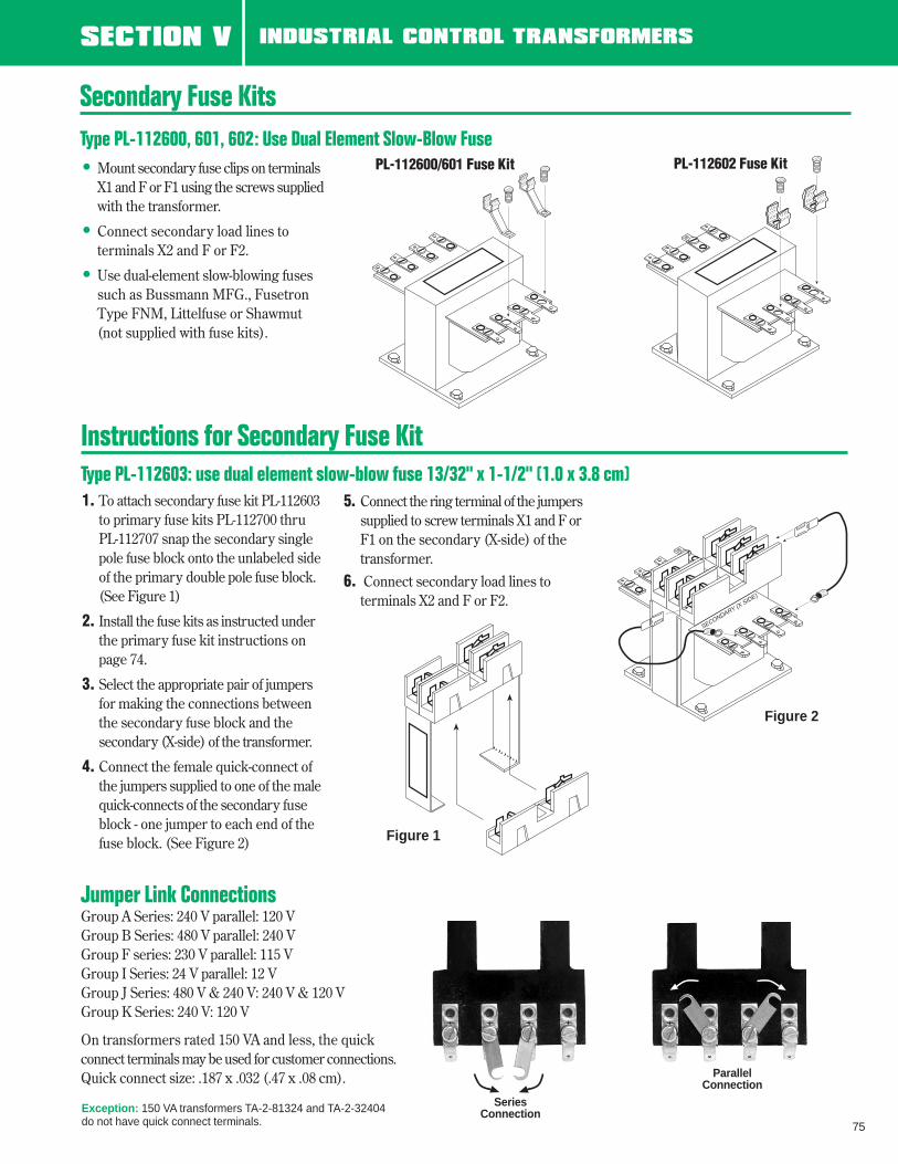
• Mount secondary fuse clips on terminalsX1 and F or F1 using the screws suppliedwith the transformer.
• Connect secondary load lines to terminals X2 and F or F2.
• Use dual-element slow-blowing fusessuch as Bussmann MFG., FusetronType FNM, Littelfuse or Shawmut(not supplied with fuse kits).
Secondary Fuse KitsType PL-112600, 601, 602: Use Dual Element Slow-Blow Fuse
PL-112600/601 Fuse Kit PL-112602 Fuse Kit
1. To attach secondary fuse kit PL-112603to primary fuse kits PL-112700 thru PL-112707 snap the secondary single pole fuse block onto the unlabeled sideof the primary double pole fuse block. (See Figure 1)
2. Install the fuse kits as instructed under the primary fuse kit instructions on page 74.
3. Select the appropriate pair of jumpersfor making the connections between the secondary fuse block and the secondary (X-side) of the transformer.
4. Connect the female quick-connect of the jumpers supplied to one of the malequick-connects of the secondary fuse block - one jumper to each end of the fuse block. (See Figure 2)
5. Connect the ring terminal of the jumperssupplied to screw terminals X1 and F orF1 on the secondary (X-side) of the transformer.
6. Connect secondary load lines to terminals X2 and F or F2.
SECONDARY (X SIDE)
Figure 1
Figure 2
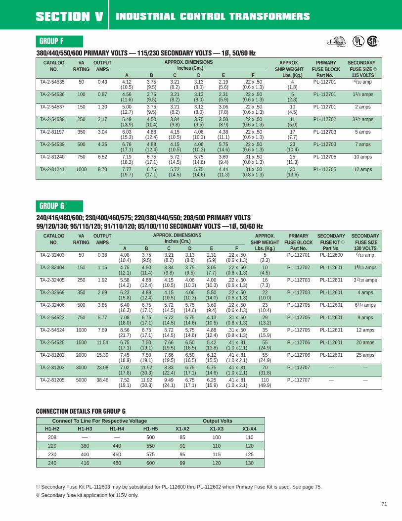
Jumper Link ConnectionsGroup A Series: 240 V parallel: 120 VGroup B Series: 480 V parallel: 240 VGroup F series: 230 V parallel: 115 VGroup I Series: 24 V parallel: 12 VGroup J Series: 480 V & 240 V: 240 V & 120 VGroup K Series: 240 V: 120 V
On transformers rated 150 VA and less, the quickconnect terminals may be used for customer connections.Quick connect size: .187 x .032 (.47 x .08 cm).
Instructions for Secondary Fuse KitType PL-112603: use dual element slow-blow fuse 13/32" x 1-1/2" (1.0 x 3.8 cm)
SeriesConnection
ParallelConnection
Exception: 150 VA transformers TA-2-81324 and TA-2-32404do not have quick connect terminals.
240 x 480 PRIMARY VOLTS—120 SECONDARY VOLTS3 —1Ø, 50/60 Hz
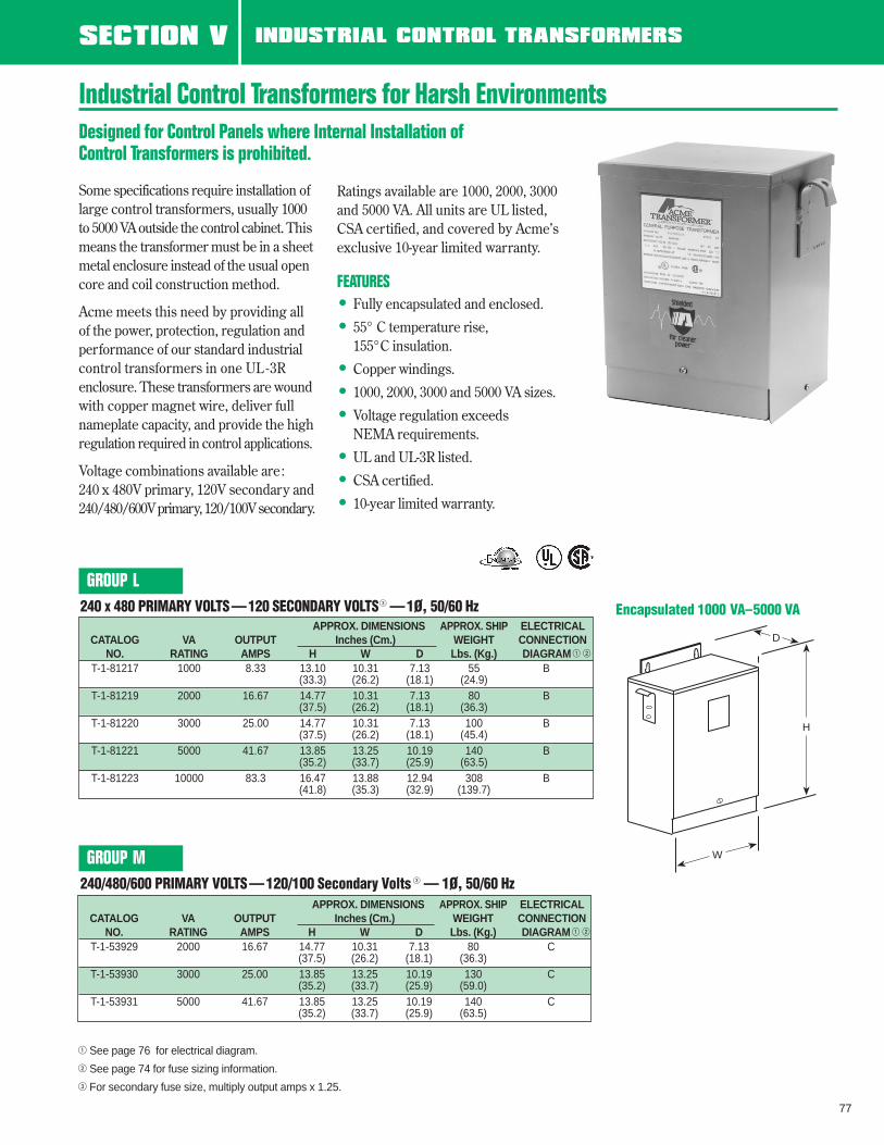
Some specifications require installation oflarge control transformers, usually 1000to 5000 VA outside the control cabinet. Thismeans the transformer must be in a sheetmetal enclosure instead of the usual opencore and coil construction method.
Acme meets this need by providing allof the power, protection, regulation andperformance of our standard industrialcontrol transformers in one UL -3Renclosure. These transformers are woundwith copper magnet wire, deliver fullnameplate capacity, and provide the highregulation required in control applications.
Voltage combinations available are:240 x 480V primary, 120V secondary and240/480/600V primary, 120/100V secondary.
Industrial Control Transformers for Harsh EnvironmentsDesigned for Control Panels where Internal Installation of Control Transformers is prohibited.
Encapsulated 1000 VA–5000 VA
1 See page 76 for electrical diagram.
2 See page 74 for fuse sizing information.
3 For secondary fuse size, multiply output amps x 1.25.
Ratings available are 1000, 2000, 3000and 5000 VA. All units are UL listed,CSA certified, and covered by Acme’sexclusive 10-year limited warranty.
SECTION V EPOXETRAN™ INDUSTRIAL CONTROL TRANSFORMERS
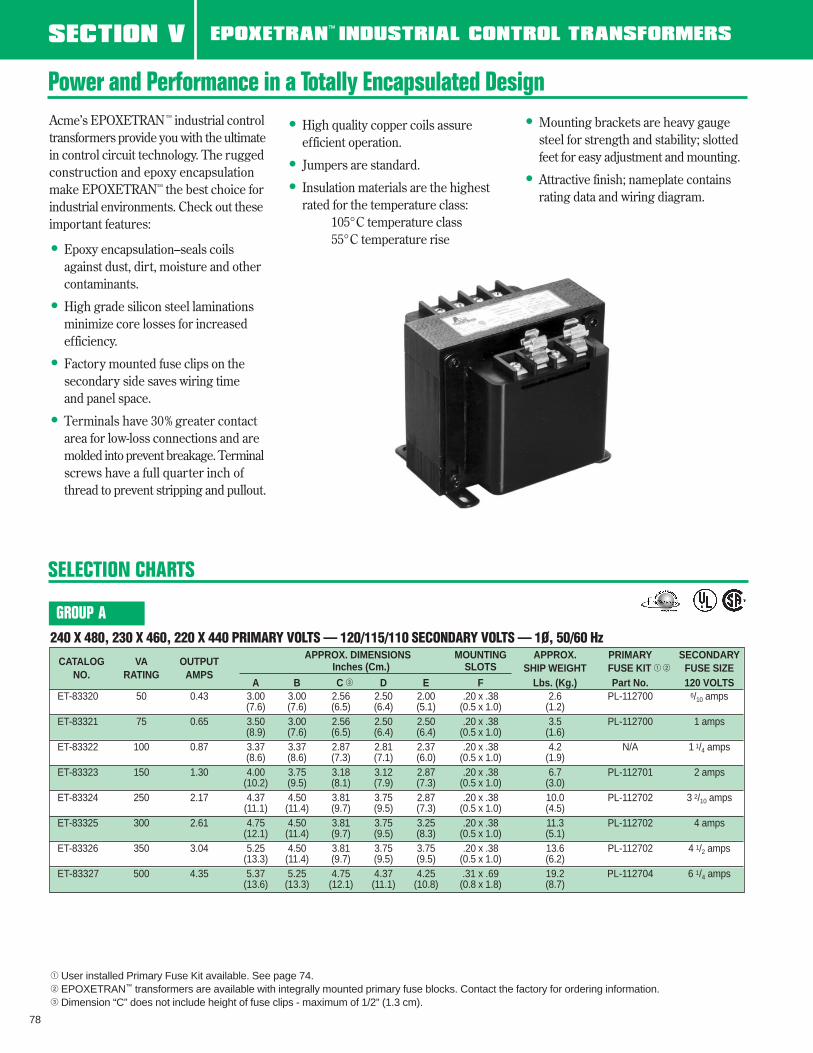
Power and Performance in a Totally Encapsulated DesignAcme’s EPOXETRAN™ industrial control transformers provide you with the ultimatein control circuit technology. The ruggedconstruction and epoxy encapsulationmake EPOXETRAN™ the best choice forindustrial environments. Check out theseimportant features:
• Epoxy encapsulation–seals coils against dust, dirt, moisture and other contaminants.
• High grade silicon steel laminations minimize core losses for increased efficiency.
• Factory mounted fuse clips on the secondary side saves wiring time and panel space.
• Terminals have 30% greater contact area for low-loss connections and are molded into prevent breakage. Terminalscrews have a full quarter inch of thread to prevent stripping and pullout.
• High quality copper coils assure efficient operation.
• Jumpers are standard.
• Insulation materials are the highest rated for the temperature class:
105°C temperature class55°C temperature rise
• Mounting brackets are heavy gauge steel for strength and stability; slottedfeet for easy adjustment and mounting.
• Attractive finish; nameplate contains rating data and wiring diagram.
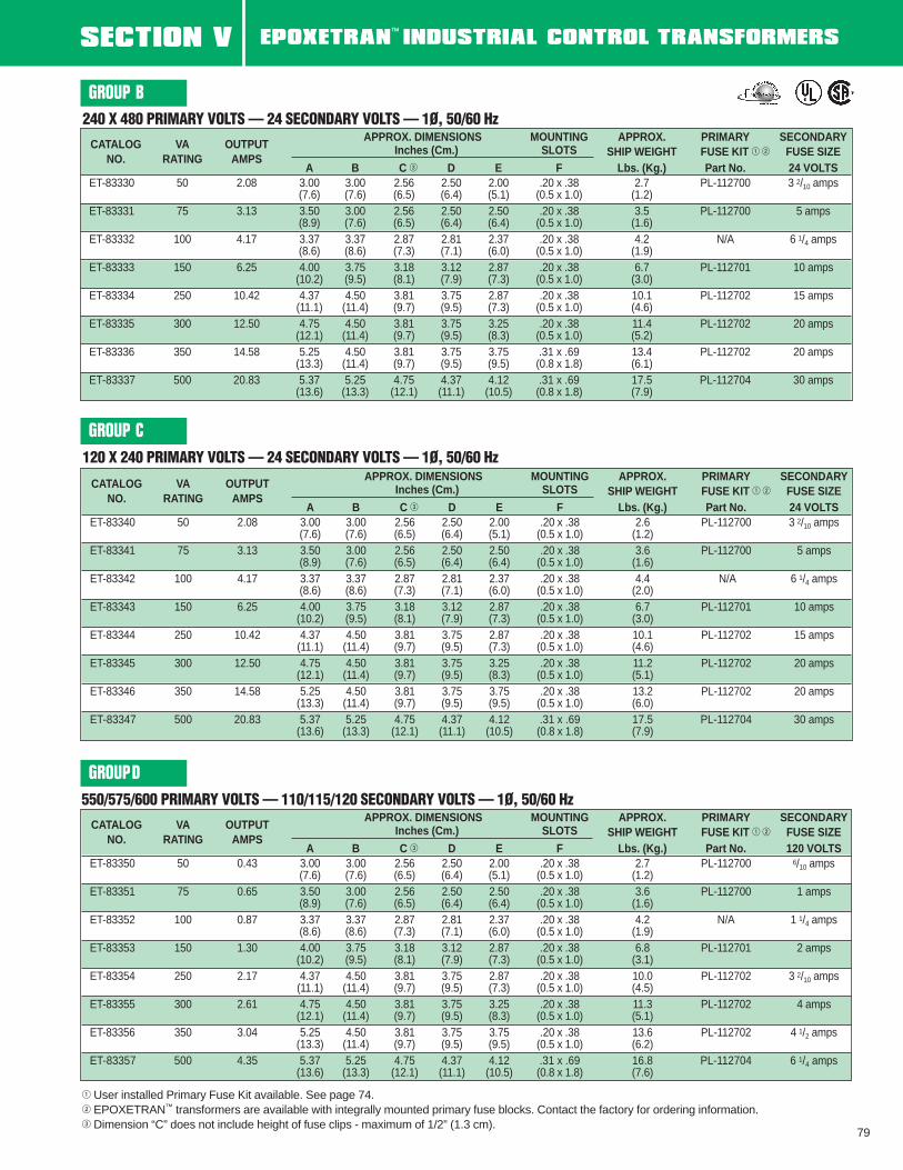
1 User installed Primary Fuse Kit available. See page 74.2 EPOXETRAN™ transformers are available with integrally mounted primary fuse blocks. Contact the factory for ordering information.3 Dimension “C” does not include height of fuse clips - maximum of 1/2” (1.3 cm).
78
240 X 480, 230 X 460, 220 X 440 PRIMARY VOLTS — 120/115/110 SECONDARY VOLTS — 1Ø, 50/60 Hz
CATALOG VA OUTPUTAPPROX. DIMENSIONS MOUNTING APPROX. PRIMARY SECONDARY
(13.6) (13.3) (12.1) (11.1) (10.8) (0.8 x 1.8) (8.7)
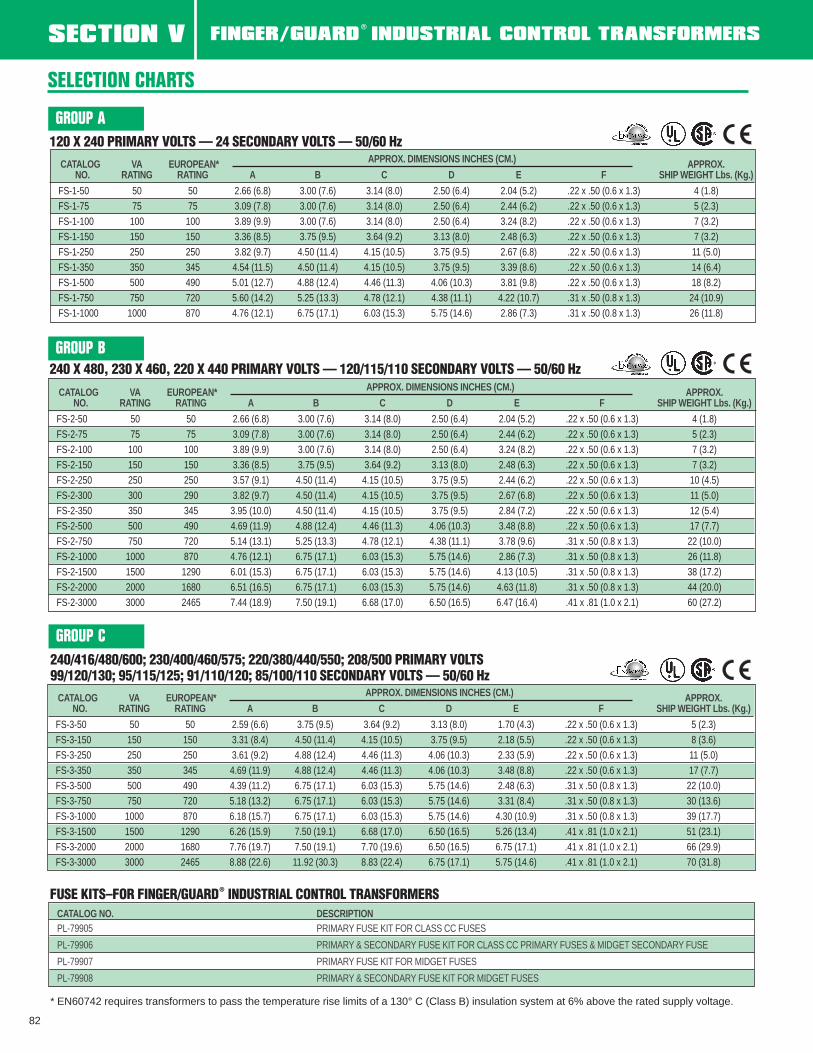
GROUP A
SELECTION CHARTS
1 User installed Primary Fuse Kit available. See page 74.2 EPOXETRAN™ transformers are available with integrally mounted primary fuse blocks. Contact the factory for ordering information.3 Dimension “C” does not include height of fuse clips - maximum of 1/2” (1.3 cm).
SECTION V EPOXETRAN™ INDUSTRIAL CONTROL TRANSFORMERS
(13.6) (13.3) (12.1) (11.1) (10.5) (0.8 x 1.8) (7.9)
GROUP B
GROUP C
GROUPD
SECTION V EPOXETRAN™ INDUSTRIAL CONTROL TRANSFORMERS
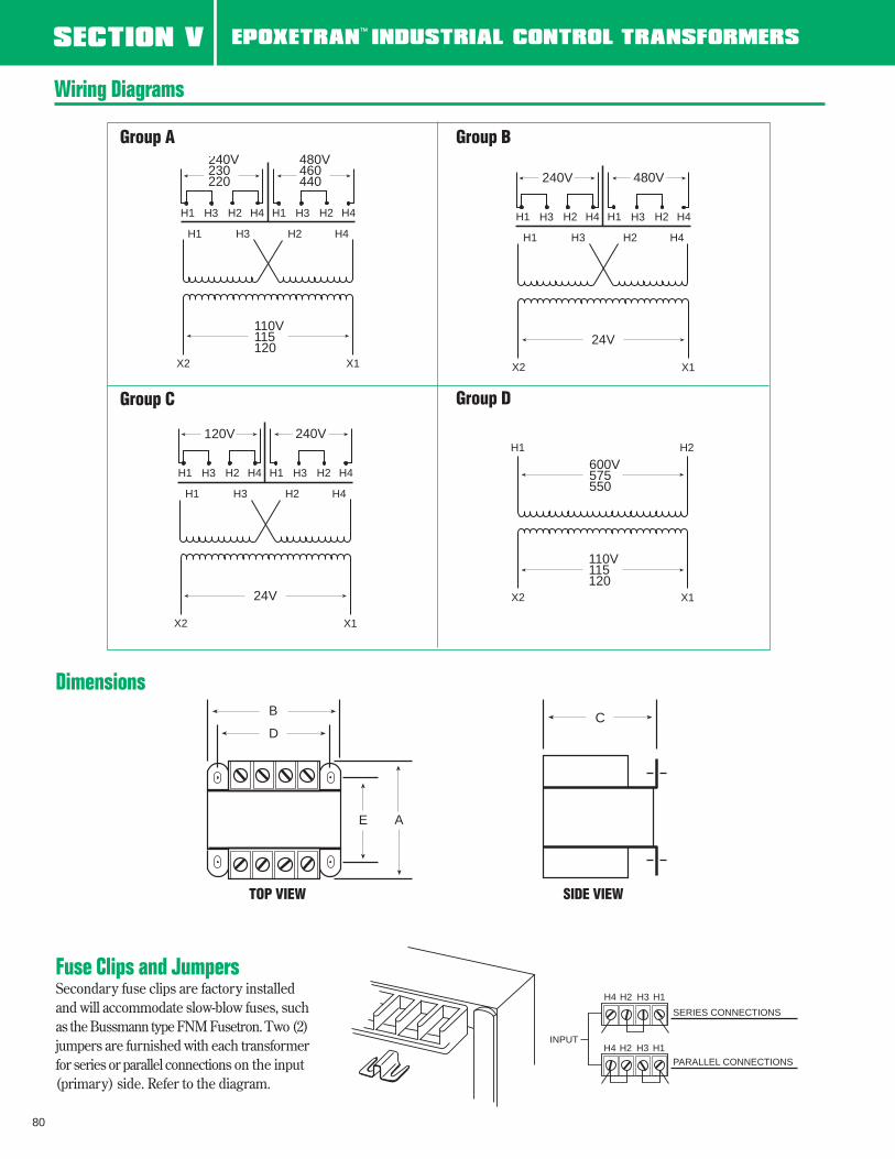
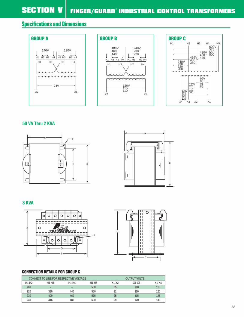
Wiring Diagrams
80
X2 X1
110V115120
480V460440
H4H3 H2H1 H4H3 H2H1
240V230220
H4H2H3H1
X2 X1
24V
480V
H4H3 H2H1 H4H3 H2H1
240V
H4H2H3H1
X2 X1
24V
240V
H4H3 H2H1 H4H3 H2H1
120V
H4H2H3H1
H2H1
X2 X1
110V115120
600V575550
Group A Group B
Group C Group D
Fuse Clips and JumpersSecondary fuse clips are factory installedand will accommodate slow-blow fuses, suchas the Bussmann type FNM Fusetron. Two (2)jumpers are furnished with each transformerfor series or parallel connections on the input(primary) side. Refer to the diagram.
DimensionsB
D
E A
C
INPUT
H4 H2 H3 H1
H4 H2 H3 H1
PARALLEL CONNECTIONS
SERIES CONNECTIONS
TOP VIEW SIDE VIEW
SECTION V FINGER/GUARD®
INDUSTRIAL CONTROL TRANSFORMERS
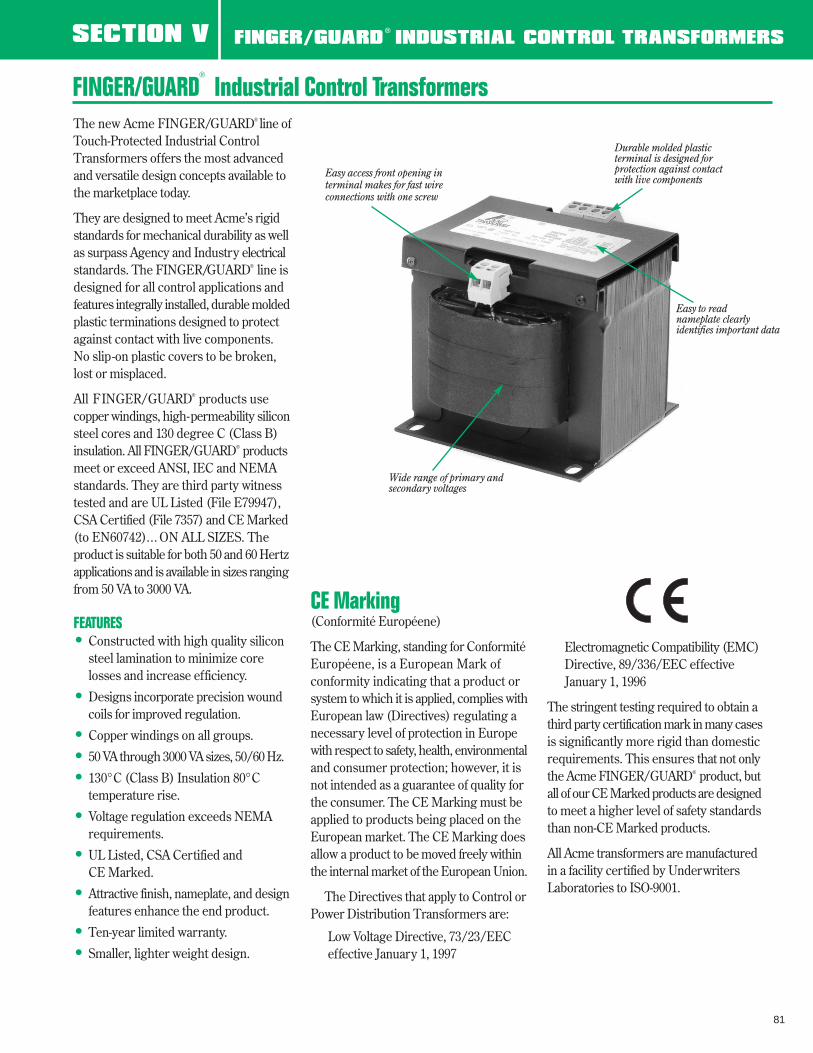
The new Acme FINGER/GUARD® line ofTouch-Protected Industrial ControlTransformers offers the most advancedand versatile design concepts available tothe marketplace today.
They are designed to meet Acme’s rigidstandards for mechanical durability as wellas surpass Agency and Industry electricalstandards. The FINGER/GUARD® line isdesigned for all control applications andfeatures integrally installed, durable moldedplastic terminations designed to protectagainst contact with live components.No slip-on plastic covers to be broken,lost or misplaced.
All FINGER/GUARD® products usecopper windings, high-permeability siliconsteel cores and 130 degree C (Class B)insulation. All FINGER/GUARD® productsmeet or exceed ANSI, IEC and NEMAstandards. They are third party witnesstested and are UL Listed (File E79947),CSA Certified (File 7357) and CE Marked(to EN60742)... ON ALL SIZES. Theproduct is suitable for both 50 and 60 Hertzapplications and is available in sizes rangingfrom 50 VA to 3000 VA.
FEATURES• Constructed with high quality silicon
steel lamination to minimize core losses and increase efficiency.
• Designs incorporate precision woundcoils for improved regulation.
• Copper windings on all groups.
• 50 VA through 3000 VA sizes, 50/60 Hz.
• 130°C (Class B) Insulation 80°Ctemperature rise.
• Voltage regulation exceeds NEMArequirements.
• UL Listed, CSA Certified and CE Marked.
• Attractive finish, nameplate, and designfeatures enhance the end product.
• Ten-year limited warranty.
• Smaller, lighter weight design.
FINGER/GUARD®
Industrial Control Transformers
CE Marking(Conformité Européene)
The CE Marking, standing for ConformitéEuropéene, is a European Mark of conformity indicating that a product orsystem to which it is applied, complies withEuropean law (Directives) regulating anecessary level of protection in Europewith respect to safety, health, environmentaland consumer protection; however, it isnot intended as a guarantee of quality forthe consumer. The CE Marking must beapplied to products being placed on theEuropean market. The CE Marking doesallow a product to be moved freely withinthe internal market of the European Union.
The Directives that apply to Control orPower Distribution Transformers are:
Low Voltage Directive, 73/23/EECeffective January 1, 1997
Electromagnetic Compatibility (EMC)Directive, 89/336/EEC effective January 1, 1996
The stringent testing required to obtain athird party certification mark in many casesis significantly more rigid than domesticrequirements. This ensures that not onlythe Acme FINGER/GUARD® product, butall of our CE Marked products are designedto meet a higher level of safety standardsthan non-CE Marked products.
All Acme transformers are manufacturedin a facility certified by UnderwritersLaboratories to ISO-9001.
Durable molded plastic terminal is designed for protection against contact with live components
Easy to read nameplate clearly identifies important data
Wide range of primary andsecondary voltages
Easy access front opening interminal makes for fast wireconnections with one screw
81
CATALOG NO. DESCRIPTIONPL-79905 PRIMARY FUSE KIT FOR CLASS CC FUSES
PL-79906 PRIMARY & SECONDARY FUSE KIT FOR CLASS CC PRIMARY FUSES & MIDGET SECONDARY FUSE
PL-79907 PRIMARY FUSE KIT FOR MIDGET FUSES
PL-79908 PRIMARY & SECONDARY FUSE KIT FOR MIDGET FUSES
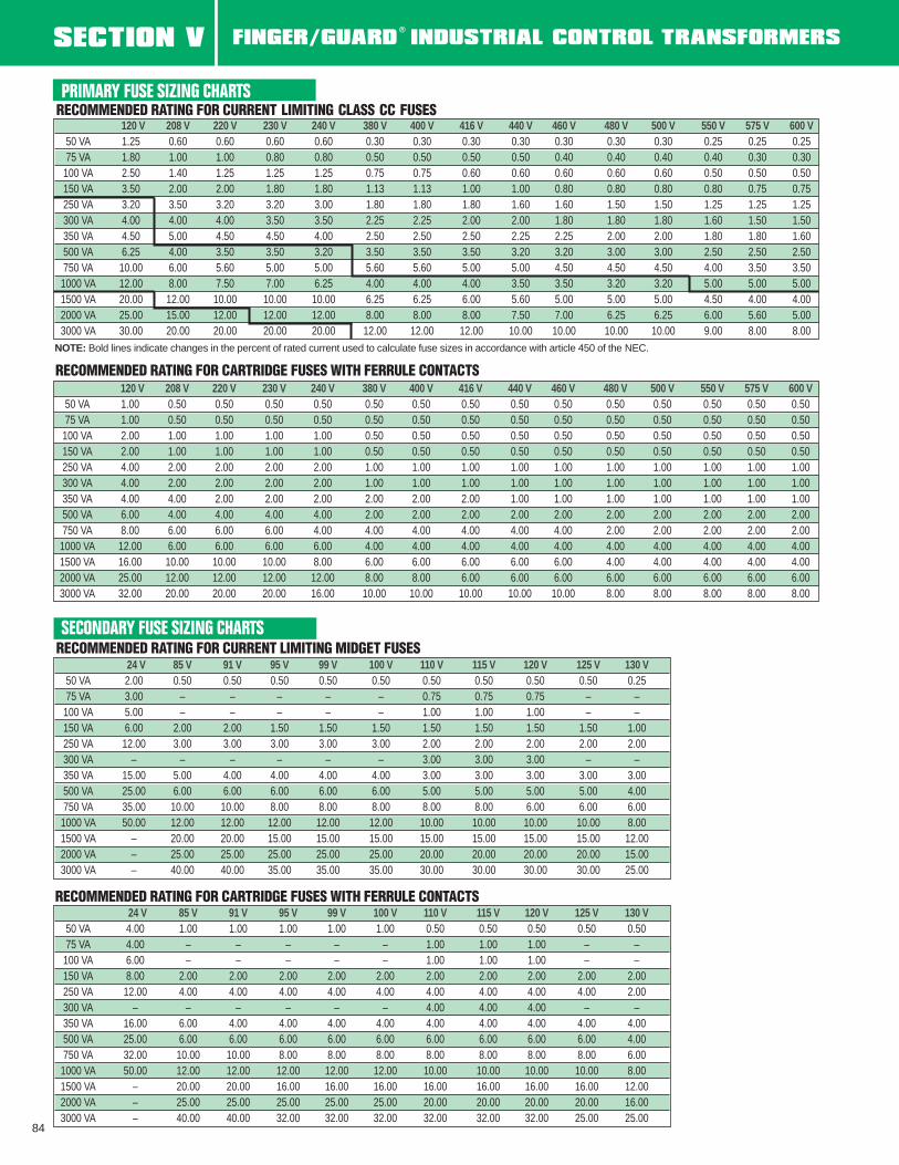
SECONDARY FUSE SIZING CHARTSRECOMMENDED RATING FOR CURRENT LIMITING MIDGET FUSES
PRIMARY FUSE SIZING CHARTSRECOMMENDED RATING FOR CURRENT LIMITING CLASS CC FUSES
RECOMMENDED RATING FOR CARTRIDGE FUSES WITH FERRULE CONTACTS
RECOMMENDED RATING FOR CARTRIDGE FUSES WITH FERRULE CONTACTS
NOTE: Bold lines indicate changes in the percent of rated current used to calculate fuse sizes in accordance with article 450 of the NEC.
84
120 V 208 V 220 V 230 V 240 V 380 V 400 V 416 V 440 V 460 V 480 V 500 V 550 V 575 V 600 V50 VA 1.00 0.50 0.50 0.50 0.50 0.50 0.50 0.50 0.50 0.50 0.50 0.50 0.50 0.50 0.5075 VA 1.00 0.50 0.50 0.50 0.50 0.50 0.50 0.50 0.50 0.50 0.50 0.50 0.50 0.50 0.50
24 V 85 V 91 V 95 V 99 V 100 V 110 V 115 V 120 V 125 V 130 V50 VA 2.00 0.50 0.50 0.50 0.50 0.50 0.50 0.50 0.50 0.50 0.2575 VA 3.00 – – – – – 0.75 0.75 0.75 – –
24 V 85 V 91 V 95 V 99 V 100 V 110 V 115 V 120 V 125 V 130 V50 VA 4.00 1.00 1.00 1.00 1.00 1.00 0.50 0.50 0.50 0.50 0.5075 VA 4.00 – – – – – 1.00 1.00 1.00 – –
120 V 208 V 220 V 230 V 240 V 380 V 400 V 416 V 440 V 460 V 480 V 500 V 550 V 575 V 600 V50 VA 1.25 0.60 0.60 0.60 0.60 0.30 0.30 0.30 0.30 0.30 0.30 0.30 0.25 0.25 0.2575 VA 1.80 1.00 1.00 0.80 0.80 0.50 0.50 0.50 0.50 0.40 0.40 0.40 0.40 0.30 0.30