56
1 Industrial energy management Reciprocating engines Jun.-Prof. Benoît Fond, G-10/R-119 [email protected]
1
Industrial energy management
Reciprocating engines
Jun.-Prof. Benoît Fond, G-10/R-119

2
Combustion devices
• In steam power plant, heat is supplied to the water from an external
source (coal, gas, nuclear fuel) via a heat exchanger (boiler) – no direct
contact.
• Working fluid is external to combustion
• Closed working fluid cycle – The fluid recirculates
• In gas turbines and reciprocating engines, chemical heat release takes
place within the working fluid.
• Internal combustion engines
• Open cycle – Air is drawn from the atmosphere and combustion products are
exhausted to the atmosphere.
Open and closed cycle / Internal and External Combustion

3
Layout
1. Basics of reciprocating engines
1. Classification
2. The Spark Ignition Engine
3. The Compression Ignition Engines
4. Fuels
5. Efficiency analysis
6. Power control
7. Emissions
2. Development strategies for reciprocating engines
1. Current challenges
2. Exhaust after treatment
3. Strategies for Spark Ignition Engines
4. Strategies for Compression Ignition Engines

4
Reciprocating engine (or Piston Engine)
Combustion chamber with a flexible wall
(piston), resulting in variable volume.
Gas pressure leads to boundary work,
which is converted to technical work
(for example by a crank mechanism)
Time response of the combustion :
• Continuously (steam motor, Gas turbine)
• Intermittently (Otto / Diesel engine)
Reciprocating engines
https://en.wikipedia.org/wiki/File:4StrokeEngine_Ortho_3D.gif

5
Reciprocating engines
1860 J.J.E. Lenoir: first reciprocating gas engine, th = 2-3% - No mixture
compression
1862 Beau de Rochas, patented the four stroke engine but did not build it
1878 Nikolaus Otto: four stroke gas engine with mixture compression,
th = 12%, Pe = 3 hp
1897 Rudolf Diesel: first engine with air compression and self ignition,
th = 26%
Today : 44% in Diesel cars, 38% in gasoline cars, max 53% in 2-
stroke marine diesel engines
A bit of history

6
Reciprocating Engines
IC Engine as powertrain : More than 100 years of development
Development driven by :
• Production Cost
• Fuel economy
• Environment concern
• Energy supply / policy
• Fun / Customer Satisfaction
Significance of IC Engine development

7
Basics of IC engines
The nature of the gas exchange:
• 4-stroke: piston movement is alternately used for work output or gas
exchange (intake, compression, expansion, exhaust stroke)
• 2-stroke: gas exchange is realized by scavenging the exhaust gas by
the fresh load (compression, expansion stroke)

8
IC Engines
Four – stroke Cycle

9
IC Engines
Four Stroke Engine
Terminology
Source: http://what-when-how.com/energy-engineering/reciprocating-engines-diesel-and-gas-energy-engineering/
10
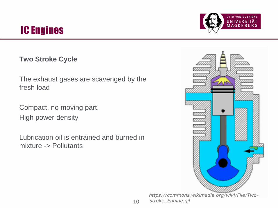
IC Engines
Two Stroke Cycle
The exhaust gases are scavenged by the
fresh load
Compact, no moving part.
High power density
Lubrication oil is entrained and burned in
mixture -> Pollutants
https://commons.wikimedia.org/wiki/File:Two-Stroke_Engine.gif

11
Basics of IC engines
Pressure level at the intake:
• Naturally aspirated engine: suction from the ambient
• Supercharged engine: increased the fresh air density using a
compressor or an exhaust turbocharger (specific power increase)
Time of the fuel input:
• Air is compressed (Diesel, „stratified GDI“)
• Mixture is compressed (Otto)
Nature of the power control:
“Quantity” of mixture (throttle) controlled (Otto)
“Quality” i.e. stoichiometry of mixture controlled (Diesel, „stratified GDI“)

12
Basics of IC engines
Nature of Ignition:
Extraneous ignition (Otto): external energy supply (spark
plug)
Self ignition (Diesel): injection of the fuel in compressed
hot air
Nature of the engine cooling:
Air or water cooling
Nature of the piston motion:
Reciprocating and rotary piston (“Wankel”) engine
Nature of the Cylinder configuration:
In-line, V, W, H, opposed cylinder engine.
https://upload.wikimedia.org/wikipedia/commons/f/fc/Wankel_Cycle_anim_en.gif

13
IC Engines
Spark Ignition Engines
Fuel and Air mix to form a combustible mixture
The mixture is compressed and then ignited near
top-dead center
Described by the Otto cycle
Constant-Volume Heat Addition
https://en.wikipedia.org/wiki/File:4StrokeEngine_Ortho_3D.gif

14
Spark ignition engine propagation
-15 CAD BTDC -13 CAD BTDC -10 CAD BTDC -8 CAD BTDC
0 CAD BTDC-5 CAD BTDC +5 CAD BTDC
Aleiferis et al. (2013)
Fuel 109,256-278
Spark happens
at -35 CAD
BTDC

15
IC Engines
Spark Ignition Engine Efficiency
Typical rv is 9, with theoretical
efficiency of 58 %.
True efficiency is 30-38%, but trend is
correct.
Limited rv to prevent pre ignition and
knock
No more lead additive -> Other design
improvements
0 5 10 150
0.1
0.2
0.3
0.4
0.5
0.6
0.7
compression ratio
effi
cien
cy

16
IC Engines
p
V
pmax
pu
Vk,OT (V +V ),h k UT
OO
ICIO
OC
hVimepdVpW
zVimepn2
1P hi
rie PPP
W work per cycle
imep indicated mean
effective pressure
n engine speed
z number of cylinders
Pe effective power (friction)
Pi internal power
Pr engine friction
V volume
Vh displaced volume
17
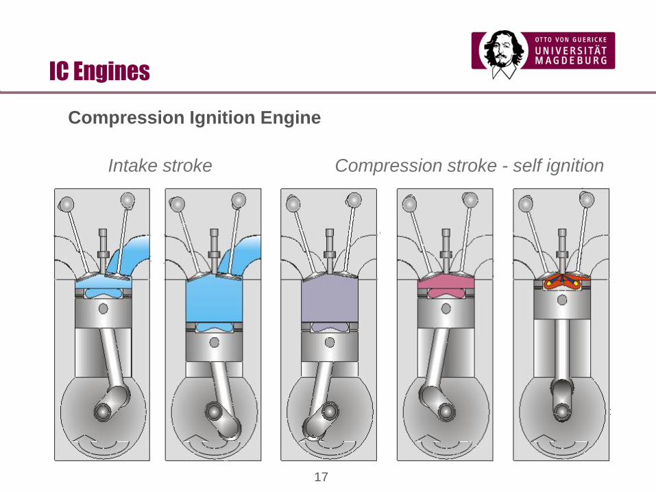
IC Engines
Intake stroke Compression stroke - self ignition
Compression Ignition Engine

18
IC Engines
Working stroke Exhaust stroke
Compression Ignition Engine

19
IC Engines
Compression Ignition Engine - Constant Pressure Heat addition
Fuel injection – Spray – Droplet – Vaporisation – Combustion
Significant time to burn fuel
Compression Ignition Engine
High-speed color imaging of a flame-wall interaction event, captured using Photron SA5 at 20,000 frames per second. Diesel was injected using a single-hole injector. Courtesy the of Advanced Combustion Diagnostics Laboratory, University of new South Wales

20
IC Engines
Typical Diesel Engine –
rv~12-30
Compression Ignition Engine

21
IC engines
Ideal engine :
• High compression ratio
• Constant volume heat addition
-> Slow Diesel Engines (Marine)
Efficiency <50 % (with turbocharging)
MAN G95ME, 110,000 hp

22
Fuels
Otto Fuels – Light compounds –high volatility (low boiling point), high
Autoignition temperature to prevent knock
Reference fuels
Octane rating - Blend of n-heptane and iso-octane which gives same
knock tendency
n-heptane C7H16: octane number 0
paraffins: single linear
iso-Octane C8H18: octane number 100
isoparaffins: branched chain,
H – C – C – C – C – C – H
H CH3 H CH3 H
H CH3 H H H
H – C – C – C – C – C –C – C – H
H H H H H H H
H H H H H H H

23
Fuels
Diesel fuel – Middle range compounds - Low volatility (high boiling point)
Low Auto-ignition temperature – Large chains
Cetane number – Blend which has same ignition delay

24
Fuels
Diesel fuel – Middle range compounds - Low volatility (high boiling point)
Low Auto-ignition temperature – Large chains
Replaced by heptamethyl nonane
Cetane number – Blend which has same ignition delay

25
Fuels
Property Gasoline Diesel
Research Octane Number 95.4
Cetane number 52
Lower Heating value (MJ/kg) 43.5 43.1
Density (kg/L @ 15°C) 0.738 0.833
Initial boiling point (°C) 28 168
Final boiling point (°C) 198.5 348
Normal paraffins, % vol. 10.8
Iso-Paraffins, % vol. 43.4
Total paraffins, % vol. 54.2 43
Naphtenes, % vol. 2.9 29
Olefins, % vol. 8.6
Aromatics, % vol. 33.6 27
Average Formula C6.64H12.11 C15.4H32.4
Some properties of a
typical gasoline and
Diesel in Europe
Source:
Kalghatgi et al., SAE
Tech. Paper 2005-
01-0239 (2005)
• Paraffins (alkanes) –
Saturated
• Olefins (alkenes) – at
least one double bond
• Naphtenes – Cyclo-
saturated
• Aromatics – Benzene
rings

26
Alternative fuels
Biofuels
1st Generation, from plants grown especially for fuel production (canola,
soya corn, sugar beets, grain)
• Biodiesel, fatty acid methyl esters (FAME), only standardised biofuel
(0.88 kg/L, LHV 37.1 MJ/kg, CN 48-67)
• Bioethanol – from crop fermentation, used blended with gasoline (up to
10 % - improves octane rating)
2nd Generation, from biomass (straw, wood) in Biomass-to-Liquid (e.g. via
Fischer-Tropsch process) – not using feedstock – CN as high as 80
Autogas (LPG)
Propane/Butane blend. RON ~90-110 HHV~28.7 MJ/kg

27
Engine efficiency
• Air cycle efficiency, e.g. Otto
Assumptions
• Fluid is air – Perfect gas, (no changes in Cp, Cv)
• Adiabatic and reversible compression and expansion
• Constant volume heat additions (instantaneous combustion)
• Constant volume heat rejection (instantaneous pressure drop, no work
required to exchange fluid)
• No mass losses

28
Indicated Cycle
• Real gas effects (power stroke) – Thermophysical properties of
evolving mixture of C,CO,CO2,H,OH,H2,H2O,N,NO,NO2,N2,O
• Strongly dependent on Φ – 31 % drop in efficiency at Φ = 1
• Time losses
• Heat losses
• Exhaust blowdown losses
• Indicated efficiency – Efficiency
of Real cycle ηI
• Combustion efficiency, ηC
For 4 strokes engines
p
V
pmax
pu
Vk,OT (V +V ),h k UT
OO
ICIO
OC
Vd: displaced volume
mf : fuel mass flow rate
Q: fuel heating value
N: rotational speed

29
Brake power
Measured at the flywheel
Pb = bmepVdN
2Prony brakeSource : The New Students Reference work
Include mechanical losses (friction, pumping losses)
Limited by Piston speed Pb = bmepApnVp
4
Specific Power (per unit Area)
Pb
Apn= bmep
Vp
4
Vd = nApS
Specific Power (per displaced volume)
Pb
Vd= bmep
Vp
4S
Vp: piston speed
Ap : piston area
n: number of cylinder
S: stroke ma: air mass flow rate
N:rotational speed F/A: fuel air ratio

30
Air rate and volumetric efficiency
If no pressure drop,
Viscous pressure drop across valve
Sonic velocity at high piston speed
Residual gases (if pe>pi)
https://en.wikipedia.org/wiki/File:4StrokeEngine_Ortho_3D.gif
31
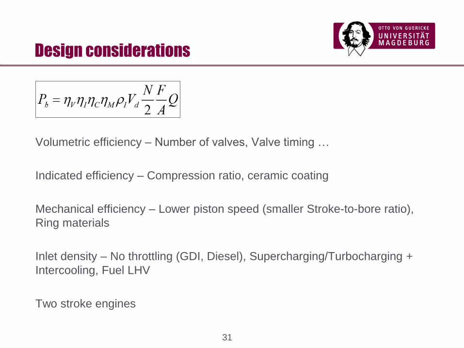
Design considerations
Volumetric efficiency – Number of valves, Valve timing …
Indicated efficiency – Compression ratio, ceramic coating
Mechanical efficiency – Lower piston speed (smaller Stroke-to-bore ratio),
Ring materials
Inlet density – No throttling (GDI, Diesel), Supercharging/Turbocharging +
Intercooling, Fuel LHV
Two stroke engines

32
Supercharging and Turbocharging
Increases inlet density
Turbo lag, Knock Source : auto.howstuffworks.com

33
Power control
p
V
pu
Vk,OT (V +V)h+k, UT
OO
ICIO
OC
High load: high amount of fuel
Low load: low amount of fuel
Low gas exchange losses
p
V
pu
Vk,OT
OOIO
High load: high inlet density
Low load: low inlet density via
throttling
High gas exchange losses
at low load conditions
IC
OC
Diesel engine Otto engine
(V +V)h+k, UT
34
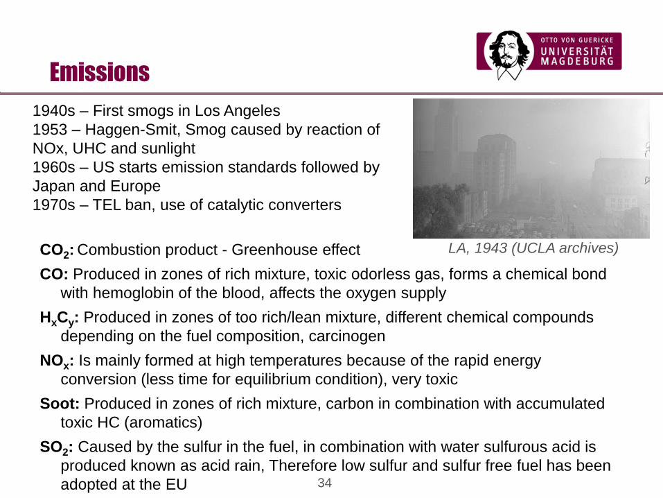
Emissions
1940s – First smogs in Los Angeles
1953 – Haggen-Smit, Smog caused by reaction of
NOx, UHC and sunlight
1960s – US starts emission standards followed by
Japan and Europe
1970s – TEL ban, use of catalytic converters
CO2: Combustion product - Greenhouse effect
CO: Produced in zones of rich mixture, toxic odorless gas, forms a chemical bond
with hemoglobin of the blood, affects the oxygen supply
HxCy: Produced in zones of too rich/lean mixture, different chemical compounds
depending on the fuel composition, carcinogen
NOx: Is mainly formed at high temperatures because of the rapid energy
conversion (less time for equilibrium condition), very toxic
Soot: Produced in zones of rich mixture, carbon in combination with accumulated
toxic HC (aromatics)
SO2: Caused by the sulfur in the fuel, in combination with water sulfurous acid is
produced known as acid rain, Therefore low sulfur and sulfur free fuel has been
adopted at the EU
LA, 1943 (UCLA archives)

35
Exhaust after treatment, 3-way catalytic converter
Co
nve
rsio
n r
ate
[%
]
Air/fuel ratio [-]
Emissions
Requires tight control on
equivalence ratio

36
Otto Engine fuel metering
Fuel and air mixed in
intake manifold.
Carburetor
Venturi effect to deliver fuel
Utilises charge cooling
Port Fuel injection
Mass flow sensor
Solenoid valve control fuel
mass flow
Tighter control on Φ
(combined with lambda
sensors)
Source :
https://en.wikipedia.org/wiki/
Carburetor

37
SI Engine Performance
Source : J. Heywood, Internal
Combustion Engine fundamentals,
McGraw-Hill
Gross indicated, Brake and Friction
Power and effective mean
pressure
Indicated and brake fuel
consumption, mechanical efficiency
Full throttle 3.8 L SI Engine (Compression ratio 8.6)

38
Diesel Engine performance
Gross indicated, brake power (Pi,
Pb) and effective mean pressure
(imep,bmep), and indicated and
brake specific fuel consumption
Full throttle 8.4 L Direct Ignition
Diesel Engine (Compression ratio 16)
Source : J. Heywood, Internal
Combustion Engine fundamentals,
McGraw-Hill

39
Traditional comparison of Otto and Diesel power train
systems
Otto (manifold injection)
• high power density
• simple exhaust after treatment
• (3-way catalytic converter)
• lower noise level
Diesel
• lower fuel consumption
• high torque
• easy application for turbo
charging
• low raw emissions (HC,
CO, CO2), but high amount
of particles & NOx
Otto and Diesel Engines

40
Challenges on vehicle development
Consumption
improvement
Internal methods (combustion chamber,
injection system, process improvement ..)
Improvement of the power train
(gear box, differential gear..)
Vehicle specific improvements
(weight, rolling drag, air drag ..)
Emission reduction
In addition: exhaust after treatment
(3-way catalytic converter, oxidation
catalytic converter, NOx storage catalytic
converter, filter systems ..)
Internal methods (combustion chamber,
injection system, process improvement ..)

41
Goal conflict • The desire of the customer (air condition, diagnostic
systems, electronic assisting systems ..)
• The need for higher passive safety (airbags, deformable
zones, crash stability ..)
Consequences Increasing vehicle weight
More energy consumers in the car
Increasing fuel consumption & emissions
More powerful engines
Challenges on vehicle development

42
weight empty:
Individual measures to save 1l / 100km in fuel consumption
(Basis: 2,0 L Gasoline(Otto) / Diesel-engine; VW Golf)
Fuel consumption
NEDC [l/100km]
Challenges on vehicle development
Otto Diesel
Fuel consumption
NEDC (l/100 km)
7,28 6,28 5,64 4,64
Empty weight 1424 860 kg ~ 40% 1445 820 kg ~ 43%
Air drag x Area 0,68 0,15 kg ~ 78% 0,68 0 kg ~ 100%
Friction coefficient 0,0100 0,0003 kg ~
66%
0,0108 0,0003 kg ~
97%
43
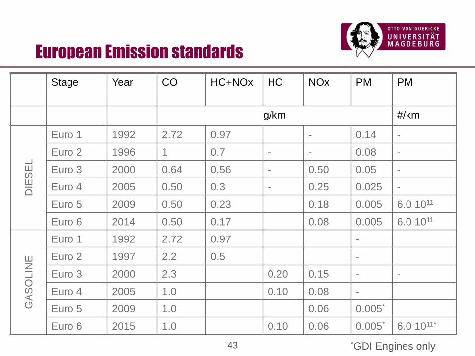
Stage Year CO HC+NOx HC NOx PM PM
g/km #/km
DIE
SE
L
Euro 1 1992 2.72 0.97 - 0.14 -
Euro 2 1996 1 0.7 - - 0.08 -
Euro 3 2000 0.64 0.56 - 0.50 0.05 -
Euro 4 2005 0.50 0.3 - 0.25 0.025 -
Euro 5 2009 0.50 0.23 0.18 0.005 6.0 1011
Euro 6 2014 0.50 0.17 0.08 0.005 6.0 1011
GA
SO
LIN
E
Euro 1 1992 2.72 0.97 -
Euro 2 1997 2.2 0.5 -
Euro 3 2000 2.3 0.20 0.15 - -
Euro 4 2005 1.0 0.10 0.08 -
Euro 5 2009 1.0 0.06 0.005*
Euro 6 2015 1.0 0.10 0.06 0.005* 6.0 1011*
European Emission standards
*GDI Engines only

44
State-of-the-art:
• 4-valve-technology: good volumetric
efficiency
• Central spark plug location: short flame
path
• 3-way catalytic converter and =1-concept:
good emissions values in stationary
operation
• Simple injection system with a high
development status
Conventional Otto engine with MPI
Development strategies

45
Optimization possibilities for the Otto engine
• Controlled intake manifold
• Supercharging & „downsizing“
• Exhaust gas recirculation
• Cylinder shut-off
• Optimization of injection and ignition
• Lean-mix engine
• Variable valve control (timing and lift)
• Gasoline direct injection (GDI)
Development strategies

46
Variable valve control
Indicator diagram schematically for:
throttling early inlet closing late inlet closing
V
pu
Vk,OT (V +V ),h k UT
OO
IC
IO
OC
p
V
pu
Vk,OT (V +V ),h k UT
ICIO
OC
OO
p
Variable valve timing

47
Operation mode of „Valvetronic“ von BMW:
1...Inlet valve
2...Camshaft
3…Eccentric shaft
4...Lever
5…servo motor
1
5
4
3
2
Variable valve lift

48
Stratified Charge concept
Gasoline Direct Injection - GDI
High load – Premixed Low load – Lean stratified

49
Gasoline Direct Injection
Potentials of gasoline direct injection (GDI)
• Higher effective and geometric compression ratio, because of internal
mixture vaporization cooling (minor knocking affinity at high loads)
• No wall wetting in the manifold
» improves the emission level at cold start and warm up conditions
» Improves the transient behaviour
• Reduction of throttling-, heat- and exhaust gas losses by using the
stratified operation
Potential in improving the fuel economy is about 15-20 %

50
Gasoline Direct Injection
Disadvantages of the gasoline direct injection engine
• Short time for mixture formation
• High amount of parameters, complex development of the operation and
combustion processes
• Stable operation over a wide range of the engine map demands a great deal on
the injection system and the electronics for controlling (EGR, injection,
ignition..)
• Wall wetting at the cylinder and the piston
• High amount HC-, Soot- und NOx- raw emissions
• 3-way exhaust catalytic converter not usable at stratified operation
• Special requirements on fuel and lubricant
• Increased energy demand (high pressure injection system, ignition system)
• Engine noise, costs

51
State-of-the-art:
• High pressure injection system (CR or unit-
injection)
• Exhaust gas turbo charger
• Exhaust gas recirculation
• Low fuel consumption
Diesel DI engine
Development strategies

52
Diesel engine emissions
Soot are formed in fuel
rich regions and then
oxidised
NOx are formed in hot
near stochiometric zones

53
Exhaust gas recirculation
EGR decreases peak
temperature by diluting
with inert gases
Compromise between
low peak temperature
and completeness of the
reactions

54
Difficulties realizing a Diesel engine with less emissions:Conflictive relation between NOX- / soot formation and consumption
Partic
les
[g/k
m]
NOx + HC / NOx [g/km]
0,3 / 0,25
0,025
0,05
0,08
0,19
0,56 / 0,50 0,9 / -- 0,97 / --
EURO II
EURO I Basis EURO I: 2,27(1992)
CO [g/km]
EURO IV: 0,50(2005)
EURO II: 1,00(1996)
EURO III: 0,64(2000)
Soot filter
DeNOx - Kat
DI technology4 valve technology-improvement
Development strategy Diesel Engine

55
Engine downsizing
Higher inlet density via turbocharging and supercharging
Smaller swept volume means :
• Less heat losses
• Less friction
• Less mass moved
Technologies :
• Waste gate (high rpm)
• Variable geometry

56
Main components of a conventional SI engine (VW, 1,4l)
Oil pump
Oil filter
Fly wheel
Cylinder head
Inlet valve
Valve spring
Cam shaft
Intake manifold
Piston
Bucket tappet
Combustion chamber
Connecting rod
Mass balance weight
Crank shaft
Exhaust manifold
Water pump
Injection valve
Construction


