18
Industrial Fabrics GEOMEMBRANES InterWrap.com
Industrial FabricsG E O M E M B R A N E S
InterWrap.com

TABLE OF CONTENTS
About Us . . . . . . . . . . . . . . . . . . . . . . . . . . . . . . . . . . . . . . . . . . 4
Manufacturing Capabilities . . . . . . . . . . . . . . . . . . . . . . . . . . . . 7
Quality Control . . . . . . . . . . . . . . . . . . . . . . . . . . . . . . . . . . . . . 9Commitment to Quality . . . . . . . . . . . . . . . . . . . . . . . . . . . . . . . . 9Product Development and Commercialization . . . . . . . . . . . . . 9Quality Organization . . . . . . . . . . . . . . . . . . . . . . . . . . . . . . . . . . 9Quality Facilities . . . . . . . . . . . . . . . . . . . . . . . . . . . . . . . . . . . . . 10Quality Assurance . . . . . . . . . . . . . . . . . . . . . . . . . . . . . . . . . . . . 10Quality Control Capabilities . . . . . . . . . . . . . . . . . . . . . . . . . . . 10Sampling and Inspection Plans . . . . . . . . . . . . . . . . . . . . . . . . . 11Inspection Records . . . . . . . . . . . . . . . . . . . . . . . . . . . . . . . . . . . 11Verification and Approval . . . . . . . . . . . . . . . . . . . . . . . . . . . . . . 11Finished Product Packaging and Labelling . . . . . . . . . . . . . . . 11Records Control and Documentation . . . . . . . . . . . . . . . . . . . . 11
RhinoMat . . . . . . . . . . . . . . . . . . . . . . . . . . . . . . . . . . . . . . . . . 13
RhinoSkin 30SG . . . . . . . . . . . . . . . . . . . . . . . . . . . . . . . . . . . . 14
RhinoSkin 12 - 30 mil . . . . . . . . . . . . . . . . . . . . . . . . . . . . . . . . 17
Fracking Containment Solutions . . . . . . . . . . . . . . . . . . . . . . . 18
Installation Instructions . . . . . . . . . . . . . . . . . . . . . . . . . . . . . . 20Applications . . . . . . . . . . . . . . . . . . . . . . . . . . . . . . . . . . . . . . . . 20ASTM References . . . . . . . . . . . . . . . . . . . . . . . . . . . . . . . . . . . . 20American Society for Testing and Materials (ASTM) . . . . . . . . 20Submittals . . . . . . . . . . . . . . . . . . . . . . . . . . . . . . . . . . . . . . . . . . 21Documents to be included in a submittal to the owner/engineer: . . . . . . . . . . . . . . . . . . . . . . . . . . . . . . . . . . . . . . . . . . . 21InterWrap Qualifications . . . . . . . . . . . . . . . . . . . . . . . . . . . . . . 21Fabricators Qualifications . . . . . . . . . . . . . . . . . . . . . . . . . . . . . 21Installer’s Qualifications . . . . . . . . . . . . . . . . . . . . . . . . . . . . . . . 21Geomembrane Arrival at Project Site . . . . . . . . . . . . . . . . . . . . 21Unloading . . . . . . . . . . . . . . . . . . . . . . . . . . . . . . . . . . . . . . . . . . 21Storage . . . . . . . . . . . . . . . . . . . . . . . . . . . . . . . . . . . . . . . . . . . . 22Installation . . . . . . . . . . . . . . . . . . . . . . . . . . . . . . . . . . . . . . . . . . 22Subgrade Preparation . . . . . . . . . . . . . . . . . . . . . . . . . . . . . . . . 22
Unfolding and Deploying Prefabricated Panels . . . . . . . . . . . 22Field Seaming . . . . . . . . . . . . . . . . . . . . . . . . . . . . . . . . . . . . . . . 22Field Cleaning of Seams . . . . . . . . . . . . . . . . . . . . . . . . . . . . . . 23Field Seaming . . . . . . . . . . . . . . . . . . . . . . . . . . . . . . . . . . . . . . . 23Field Thermal Seaming (solid wedge only) . . . . . . . . . . . . . . . 23Field Tape Seaming . . . . . . . . . . . . . . . . . . . . . . . . . . . . . . . . . . 24Field Seaming Test Requirements . . . . . . . . . . . . . . . . . . . . . . 24Test Seams (Trial Seams) . . . . . . . . . . . . . . . . . . . . . . . . . . . . . . 24Non-Destructive Testing (NDT) of Seam Testing . . . . . . . . . . . 25Air Lance Testing (ASTM D 4437) . . . . . . . . . . . . . . . . . . . . . . . 25Mechanical Point Stress or “Pick” test (ASTM D4437) . . . . . . 25Identification of Defects . . . . . . . . . . . . . . . . . . . . . . . . . . . . . . 26Evaluation of Defects . . . . . . . . . . . . . . . . . . . . . . . . . . . . . . . . . 26Geomembrane Penetrations . . . . . . . . . . . . . . . . . . . . . . . . . . . 26
i . Pipes . . . . . . . . . . . . . . . . . . . . . . . . . . . . . . . . . . . . . . . . . . 26ii . Concrete . . . . . . . . . . . . . . . . . . . . . . . . . . . . . . . . . . . . . . 27iii . Drains . . . . . . . . . . . . . . . . . . . . . . . . . . . . . . . . . . . . . . . . 27iv . Aerators . . . . . . . . . . . . . . . . . . . . . . . . . . . . . . . . . . . . . . . 27
Cover Materials . . . . . . . . . . . . . . . . . . . . . . . . . . . . . . . . . . . . . 27Field Acceptance . . . . . . . . . . . . . . . . . . . . . . . . . . . . . . . . . . . . 28Site Clean Up and Demobilization . . . . . . . . . . . . . . . . . . . . . . 28
InterWrap Family of Products . . . . . . . . . . . . . . . . . . . . . . . . . 30Synthetic Roofing Underlayment . . . . . . . . . . . . . . . . . . . . . . . 30Protective Packaging - Wood . . . . . . . . . . . . . . . . . . . . . . . . . . 30Protective Packaging - Metal . . . . . . . . . . . . . . . . . . . . . . . . . . 30Custom Coating & Laminating . . . . . . . . . . . . . . . . . . . . . . . . . 30
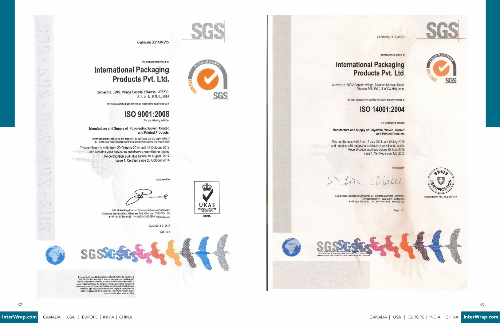
ISO 9001:2008 . . . . . . . . . . . . . . . . . . . . . . . . . . . . . . . . . . . . . 32
ISO 14001:2004 . . . . . . . . . . . . . . . . . . . . . . . . . . . . . . . . . . . . 33
ISO 18001:2007 . . . . . . . . . . . . . . . . . . . . . . . . . . . . . . . . . . . . 34
Key Contacts . . . . . . . . . . . . . . . . . . . . . . . . . . . . . . . . . . . . . . 35Sales - North America & Europe: . . . . . . . . . . . . . . . . . . . . . . . 35Sales - India & Asia: . . . . . . . . . . . . . . . . . . . . . . . . . . . . . . . . . . 35Technical Support: . . . . . . . . . . . . . . . . . . . . . . . . . . . . . . . . . . . 35Head Office: . . . . . . . . . . . . . . . . . . . . . . . . . . . . . . . . . . . . . . . . 35
32
InterWrap.com CANADA | USA | EUROPE | INDIA | CHINA CANADA | USA | EUROPE | INDIA | CHINA InterWrap.com

InterWrap® is a vertically integrated, global manufacturer of innovative coated woven products
and diverse multi-layer laminated reinforced plastic substrates . InterWrap serves a wide
variety of markets such as synthetic roofing underlayments, protective packaging - lumber
& metal wrap, geomembranes, converted fabrics, agricultural and construction products .
Consistent product quality is achieved by using state-of-the-art plastic extrusion, weaving,
coating, laminating, printing techniques and a strong commitment to partnership with our
customers, employees and suppliers .
ABOUT US
Canada
Headquarters, Downtown Vancouver BC
300, 000 sq ft of manufacturing facilities in Mission BC and Dorval, QC
USA
170, 000 sq ft manufacturing facility in Charleston, SC India
250, 000 sq ft manufacturing facilities in Dapada and Sayli
China
290, 000 sq ft manufacturing facility in Jiaozhou
• InterWrap® - since 1984
• ISO 9001:2008, 14001:2004 & 18001:2007 certified
• GAI - LAP Approved Laboratory
• Private corporation
• USD $250 m+ for fiscal 2015
• Over 1200 employees worldwide
• Integrated manufacturer of coated woven polyolefin products
• Entrepreneurial, speed to market culture
• Growth of 20% per annum since inception
• Doubled in size over the past 3 years
• R&D focused
• Committed to environmentally sustainable solutions
• Lean manufacturing
• Expanding globally: Manufacturing, Distribution and Markets
COMPANY HIGHLIGHTS
4
InterWrap.com CANADA | USA | EUROPE | INDIA | CHINA

InterWrap’s Headquarters are situated in Downtown Vancouver BC . Our two Canadian
manufacturing facilities are located in Mission, British Columbia & Montreal, Québec . Our
Canadian plants combined are equal to 300,000 square feet and are a key part of our North
American manufacturing operations . Strategically positioned, these state-of-the-art facilities
enable us to expedite goods to the West and East coasts of Canada and the U .S .A .
.
Established in 2002, InterWrap India has two strategically situated manufacturing plants in
South East Asia that are fully equipped to manufacture coated woven fabrics, building and
construction materials, industrial fabrics, lumber and metal wraps . Combined, our Dapada
and Sayli plants occupy 250 000 square feet . They are a vital part of our manufacturing
effectiveness and ability to successfully compete in global markets .
Established in 2007, our China facility is located in the Jiazhou province within very close
proximity to two major export ports . With 290,000 square feet of world class manufacturing
equipment and easy access to major shipping ports, our China manufacturing plant is ideally
positioned to provide rapid delivery to our growing global clientele .
Our Charleston, SC location covers 170,000 square feet and is equipped for manufacturing
and warehousing . Strategically situated on the East Coast of the United States this large
facility allows InterWrap to serve our US East Coast clients even more efficiently .
MANUFACTURING CAPABILITIES
• ISO 9001:2008, 14001:2004, 18001:2007 Certified
• GAI LAP - approved laboratory
• Over 1,000,000 sq ft of manufacturing space with a
capacity of over 20, 000,000 LF per year
• Weaving looms; flat & circular, up to 144”
• Tape extrusion lines
• Extrusion coating lines, up to 144”
• Printing presses; up to 144” and 4 colors
• Slitting, cutting & rewinding machines
• Converting lines; sewing & heat sealing
• Laminating; paper, foil, film, non-woven
7
CANADA | USA | EUROPE | INDIA | CHINA InterWrap.com

QUALITY CONTROL
Commitment to QualityInterWrap Group is committed to provide a dependable supply of products and services that consistently meet the customer’s expectations and all applicable product-specific standards . All business units of InterWrap Group operate on a quality business management system that is certified to an international standard ISO-9001:2008 .
Product Development and CommercializationThe development and innovation of products is carried out through a robust product development and commercialization process . Verification and validation runs are performed to confirm that the process produces consistent results and the product meets design specifications before proceeding to full scale commercialized production . Our research and development center is located in our Mission, B .C ., Canada facility . This R&D center is used for developing and/or adjusting present product selection, as a display center and application testing with actual on going tests per market served .
Quality Organization InterWrap’s Quality team consists of a Quality Manager, R&D Manager and Process Engineers, Quality Assurance/Quality Control Coordinators, Quality testing facilities and manufacturing personnel . The team is responsible for ensuring the system is functioning correctly, that raw material and finished goods inspections are being conducted according to established protocols, and that established identification and traceability standards are maintained .
Quality Manager:Maintenance and improvement of the MQA program . Development and approval of all raw material and finished fabric inspection plans .
R&D Manager, Process Engineers:Product development and commercialization, including verification and validation trials . Approval of raw material specifications . Development and approval of all finished sheet product specifications .
9
CANADA | USA | EUROPE | INDIA | CHINA InterWrap.com
8
InterWrap.com CANADA | USA | EUROPE | INDIA | CHINA

QUALITY CONTROL QUALITY CONTROL
Quality Facilities
InterWrap’s manufacturing facilities maintain high capacity testing laboratories outfitted with
modern equipment capable of performing most of the referenced tests .
InterWrap also utilizes hard and soft Quality Management database to house all of its raw
material product specifications, raw material and finished fabric product inspection plans and
records, and related process inspection data .
Quality Assurance
Incoming Raw Materials InterWrap Group has developed and maintains full specifications for the resins used in the manufacture of Geomembranes sheet .
Resins Resins are the base polyolefin materials used in the manufacture of Geomembranes fabrics . Each resin lot is provided with a product quality certification from the vendor . All incoming resins are inspected and tested prior to production use . Inspection results are entered into InterWrap’s different tools MS Log Quality Management Database . InterWrap has developed clear policies for the identification and traceability of resin material to ensure that only tested and approved materials are used in the manufacture of Geomembrane fabric .
Additive MasterbatchesVarious additive masterbatches are blended with natural resins in different proportions to achieve the desired properties of Geomembrane fabric . All masterbatches are purchased and verified against the approved material specifications before these are released to manufacturing .
Product Identification and TraceabilityInterWrap has developed a system to identify the Geomembrane products . Each Geomembrane product is assigned with a unique product identifier or stock keeping unit (SKU) . An enterprise resource planning (ERP) software is utilized to manage these product identifiers . Each Geomembrane roll is labelled with the product identifier, job number, roll number and the product description . Details of the labelling specifications are provided in Appendix E - Finished Product Packaging and Labelling . Any Geomembrane roll that does not meet the product specifications is identified and segregated to prevent its release or delivery . The process owner of a quality system database maintains the records of non-conforming Geomembrane products . The traceability of raw materials and Geomembrane product lot is maintained in the electronic quality system database and the ERP software .
Quality Control Capabilities InterWrap’s manufacturing facilities maintain a quality control system with capabilities anchored on three facets:
1 . People: The required testing are performed by highly capable and well trained personnel . Training programs of personnel are on file for review .
2 . Equipment: State-of-the-art equipment that is suitable for performing the required product testing . Calibration and maintenance records are on file for review .
3 . Methods: Industry standard test methods are employed to monitor the product quality .
Sampling and Inspection Plans InterWrap has instituted a product inspection system that is guided by industry standards and by customer requirements . A Geomembrane lot must meet both the sampling and inspection requirements to qualify for shipment . Finished Geomembrane Sampling and Testing Specifications define the minimum sampling and testing protocol for all Geomembrane products . A selection of roll samples from each manufacturing lot is retained should future testing be required . These samples have the same label information as the Geomembrane rolls . The storage method prevents the deterioration of the samples .
Inspection Records InterWrap maintains a quality system database to collect, store and analyze the inspection data . All the inspection data are available to different work groups within the organization . InterWrap can provide signed mill certificates for each Geomembrane lot or roll produced . The mill certificate provides the actual results for the specified quality attributes and validates that each product meets the Geomembrane roll specifications as published on the InterWrap website or as submitted by the InterWrap authorised personal to the respective customer for the respective product .
Verification and Approval . The InterWrap quality system requires that the test results have to be reviewed and signed off or Acknowledged by approving authorities prior to shipment for their correctness within specification . This prevents the shipping of Geomembrane rolls that do not meet the product specifications . The Quality system database indicates the status of a Geomembrane roll . The database is integrated with the shipping process through existing process controls .When necessary, an independent verification is carried out by an external laboratory . The selection of a third-party laboratory is done in concurrence with the customer requirements .
Finished Product Packaging and Labelling The packaging and labelling specifications are communicated to the production group through the job order # system . The Geomembranes rolls are weather resistant and do not require further packaging . The minimum packaging and labelling requirements are indicated in the Finished Geomembrane Packaging and Labelling Specifications .
Records Control and Documentation The documentation required to effectively implement the quality system are electronically controlled and maintained . The majority of the quality and manufacturing records are maintained electronically in soft files and hard files as well . A back-up and redundancy protocol is in placed to ensure that electronic records are available and protected . The quality system defines the accountability, method and retention period for all paper-based quality and manufacturing records .
1110
InterWrap.com CANADA | USA | EUROPE | INDIA | CHINA CANADA | USA | EUROPE | INDIA | CHINA InterWrap.com

13
CANADA | USA | EUROPE | INDIA | CHINA InterWrap.com
• SurFlex™ surface technology provides superior
welding characteristics & industry leading resistance
to stress cracking
• Unequaled mechanical strength, tear and
puncture resistance due to our proprietary layered
construction
• Low unit weight and superior seaming allows for
construction of large prefabricated panels
• Environmentally responsible recovery and recycling
program
• Puncture, abrasion and chemical resistant
construction with a high strength HDPE woven core
that provides superior dimensional stability
• Outstanding UV, ozone & oxidation resistance
• Non-toxic, no PVC or other hazardous materials
used in construction of fabric
• Low water vapor permeance
RHINOMAT
FEATURES & BENEFITS
RhinoMat is a reinforced polyethylene geomembrane that offers exceptional hydrostatic
resistance for buried and unburied containment applications . For applications where liquid
containment is critical, RhinoMat’s durable and lightweight construction, combined with our
Surflex™ technology for superior welding characteristics, will give you maximum performance
in all climates and environmental conditions .
Designed for easy installation and long life, RhinoMat is an extremely durable and light weight
fabric that is the ideal containment solution for applications such as:
• Irrigation and canal liners• Golf course and decorative pond liners• Soil remediation pads• Daily and interim landfill covers• Shale oil and gas development, e .g ., drill pads and various liquid containment• Oil and gas production, e .g ., various secondary containment applications• Floating covers• Water reservoirs and ponds• Paved and unpaved roadways• Subgrade protection• Temporary erosion control • Barriers, blankets, and curtains• Rain sheets for Ore in Mining applications• Raincoats for heap leach pad covers• Underslab vapor retarders
Safe for potable drinking water
GeosyntheticAccreditation Institute
GAI - LAP Approved Laborator y
The smart choice for water retention, containment, pond and canal lining applications .
Be water smart
12
InterWrap.com CANADA | USA | EUROPE | INDIA | CHINA
RHINOSKIN 30SG
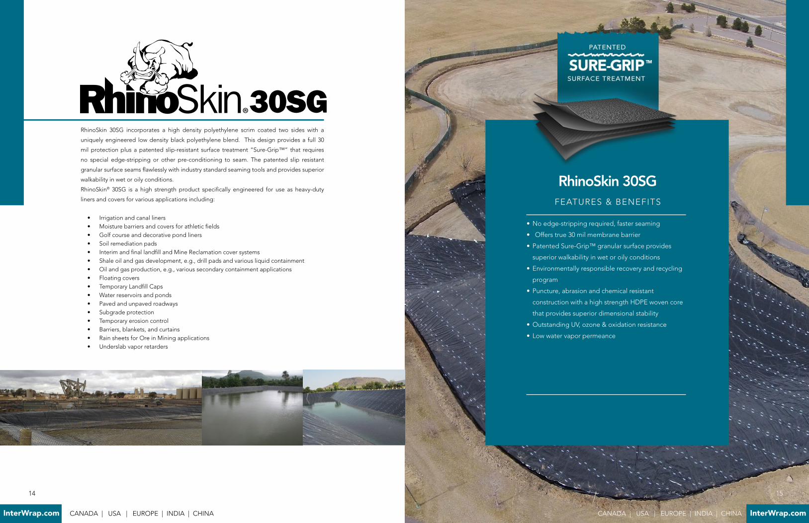
RhinoSkin 30SG incorporates a high density polyethylene scrim coated two sides with a
uniquely engineered low density black polyethylene blend . This design provides a full 30
mil protection plus a patented slip-resistant surface treatment “Sure-Grip™” that requires
no special edge-stripping or other pre-conditioning to seam . The patented slip resistant
granular surface seams flawlessly with industry standard seaming tools and provides superior
walkability in wet or oily conditions .
RhinoSkin® 30SG is a high strength product specifically engineered for use as heavy-duty
liners and covers for various applications including:
• Irrigation and canal liners• Moisture barriers and covers for athletic fields• Golf course and decorative pond liners• Soil remediation pads• Interim and final landfill and Mine Reclamation cover systems• Shale oil and gas development, e .g ., drill pads and various liquid containment• Oil and gas production, e .g ., various secondary containment applications• Floating covers• Temporary Landfill Caps • Water reservoirs and ponds• Paved and unpaved roadways• Subgrade protection• Temporary erosion control • Barriers, blankets, and curtains• Rain sheets for Ore in Mining applications• Underslab vapor retarders
FEATURES & BENEFITS
30SG
• No edge-stripping required, faster seaming
• Offers true 30 mil membrane barrier
• Patented Sure-Grip™ granular surface provides
superior walkability in wet or oily conditions
• Environmentally responsible recovery and recycling
program
• Puncture, abrasion and chemical resistant
construction with a high strength HDPE woven core
that provides superior dimensional stability
• Outstanding UV, ozone & oxidation resistance
• Low water vapor permeance
RhinoSkin 30SG
15
CANADA | USA | EUROPE | INDIA | CHINA InterWrap.com
14
InterWrap.com CANADA | USA | EUROPE | INDIA | CHINA
17
CANADA | USA | EUROPE | INDIA | CHINA InterWrap.com
RHINOSKIN 12 - 30 MIL
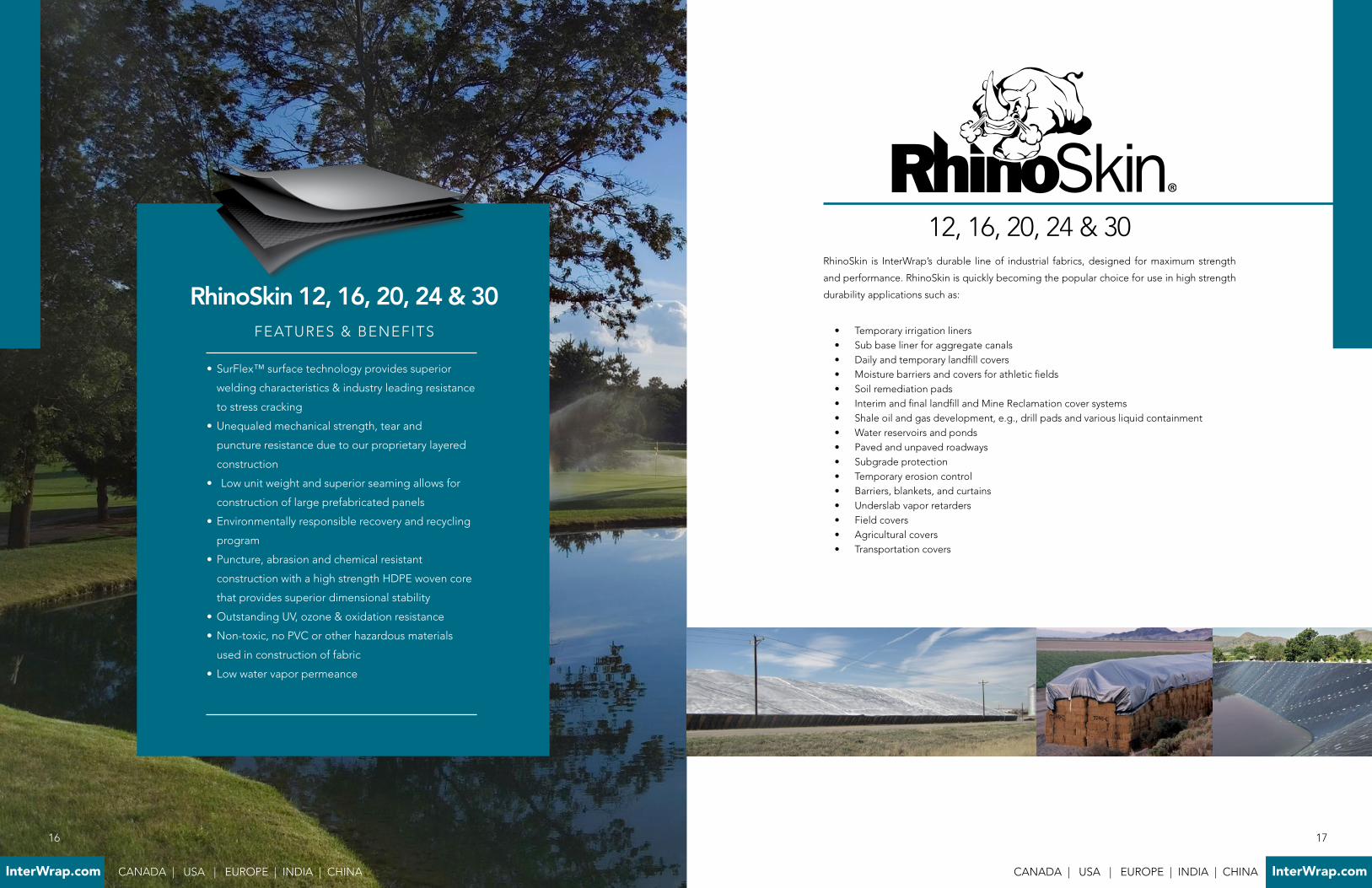
RhinoSkin is InterWrap’s durable line of industrial fabrics, designed for maximum strength
and performance . RhinoSkin is quickly becoming the popular choice for use in high strength
durability applications such as:
• Temporary irrigation liners• Sub base liner for aggregate canals• Daily and temporary landfill covers• Moisture barriers and covers for athletic fields• Soil remediation pads• Interim and final landfill and Mine Reclamation cover systems• Shale oil and gas development, e .g ., drill pads and various liquid containment• Water reservoirs and ponds• Paved and unpaved roadways• Subgrade protection• Temporary erosion control • Barriers, blankets, and curtains• Underslab vapor retarders• Field covers• Agricultural covers• Transportation covers
RhinoSkin 12, 16, 20, 24 & 30
12, 16, 20, 24 & 30
• SurFlex™ surface technology provides superior
welding characteristics & industry leading resistance
to stress cracking
• Unequaled mechanical strength, tear and
puncture resistance due to our proprietary layered
construction
• Low unit weight and superior seaming allows for
construction of large prefabricated panels
• Environmentally responsible recovery and recycling
program
• Puncture, abrasion and chemical resistant
construction with a high strength HDPE woven core
that provides superior dimensional stability
• Outstanding UV, ozone & oxidation resistance
• Non-toxic, no PVC or other hazardous materials
used in construction of fabric
• Low water vapor permeance
FEATURES & BENEFITS
16
InterWrap.com CANADA | USA | EUROPE | INDIA | CHINA

A
C
D
D B
A B
C D
many of products . RhinoMat can be used to build step panel liners for above ground storage
tanks up to 250ft in diameter with up to 16ft high walls . Installer testimonials also claim product
ease of handling and welding account for up to 20% savings in cutting and install labor .
One of RhinoMat 750 primary uses is for the capping coal ash containments . The main reason
for this is that RhinoMat is 25% lighter than PVC and can be fabricated into 30% larger panels
reducing field seams by 60% . RhinoMat also offers far more resistant to tear propagation and
has superior puncture strength . Its ability to stretch and conform to irregular surfaces also
makes it an ideal product for use with Coal Ash with its inherent requirement to settle over
time . RhinoMat 750 can also be third party leak detected for quality control of the site . For
the energy market this means it can with stand the weight and size of cuttings pits and large
multi acre ponds used in containing fresh water .
FRACKING CONTAINMENT SOLUTIONS
All of InterWrap’s RPE products are designed to hold water, however, the best solution for in
ground water and liquid storage is RhinoMat 500 or for longer life ponds RM 750 . These two
products offer the superior reliably and longevity of HDPE, the flexibility and ease of handling
of PVC, and better puncture resistance than LLDPE . RhinoMat liners are lighter and can be
fabricated into larger panels than PVC, LLDPE or HDPE products .
InterWrap’s Reinforced Polyethylene (RPE) products are designed specifically with the energy
markets of North America in mind . The primary objective has been to maximize quality and
reliability while still keeping a focus on cost and value . RhinoSkin and RhinoMat products
have been engineered for industry leading strength and reliability to meet the demands of
the drilling fields of North America . These products incorporate ease of installation combined
with capability to withstand the hottest temperatures of the Eagle Ford or the cold polar
vortex in the Bakken basin . Ease of handling and use is paramount to getting jobs done
on time and under budget .
RhinoSkin is a secondary containment for use as a pad liner with options to add a
specially formulated “Safe-T-Grip” slip resistant walking surface . RhinoSkin
is one of strongest and most durable products available with greater
puncture and tear strength than more expensive substitute
products . Dollar for dollar, RhinoSkin offers the best value
available on containment protection .
RhinoMat series liners are engineered with
heavy duty containment in mind . RhinoMat
is suitable for the most sensitive locations
near precious land and water supplies to
the most demanding strength requirements
of above ground storage tanks . Its linear
low-density polyethylene (LLDPE) film
laminate structure combined with a HDPE
reinforced core meets these challenges .
With RhinoMat products you are insured of
no pin-holing leaks, or memory creases from
transportation or installation . They offer
extremely high puncture and Mullen burst
ratings similar to much thicker High-Density
Polyethylene (HDPE) products . RhinoMat
also features long term UV life expectancy
for up to 20-year exposure for applications
that need to hold containment of liquids
and solids . RhinoMat 750 is known industry
wide as the replacement for costly 30 to 40 mil LLDPE
or reinforced LLDPE series liners . In fact, in comparison
RhinoMat offers strong seams and higher puncture resistance than
RhinoMat 750 is a 30 mill RPE liner
which offers superior cold weather install
performance compared to competitors 30
or 40 mil LLDPE products. Furthermore,
RM 750 also offers the strongest puncture
resistance on the market. Rest assured that
RM750 will hold water, save install time and
costs, and on average will offer a 30-40%
cost savings compared to other current tank
lining products currently deployed.
RhinoSkin 30 with Safe-T-Grip® walking
surface treatment is the best low cost
alternative to other anti-slip pad liners on
the market. Be on budget and save time by
installing a premium slip resistant system.
All of InterWrap’s RPE products are designed
to hold water, however, the best solution
for in ground water and liquid storage is
RhinoMat 500 or for longer life ponds RM
750. These two products offer the superior
reliably and longevity of HDPE, the flexibility
and ease of handling of PVC, and better
puncture resistance than LLDPE. RhinoMat
liners are lighter and can be fabricated into
larger panels than PVC, LLDPE or HDPE
products.
InterWrap’s RhinoMat 500 is specifically
engineered to withstand chemical elements
and field abuse.
19
CANADA | USA | EUROPE | INDIA | CHINA InterWrap.com
18
InterWrap.com CANADA | USA | EUROPE | INDIA | CHINA

21
CANADA | USA | EUROPE | INDIA | CHINA InterWrap.com
INSTALLATION INSTRUCTIONS
Installation guideline for factory fabricated panels out of RhinoSkin and RhinoMat . This
guideline is designed to provide a minimum set of standards for site installation . However,
depending on the complexity and project specific requirements, a qualified design engineering
firm may be required for design and installation specifications of the geomembrane . All work
shall be in accordance with the project drawings, specifications and QC requirements .
These Installation instructions are based on guidelines set out by the Fabricated Geomembrane Institute.
ApplicationsTypical applications for factory fabricated RhinoSkin and RhinoMat geomembranes that are less than 25 mil (0 .64 mm) in thickness include but are not limited to:
• Irrigation and canal liners• Moisture barriers and covers for athletic fields• Golf course and decorative pond liners• Soil remediation pads• Interim and final landfill and Mine Reclamation cover systems• Shale oil and gas development, e .g ., drill pads and various liquid containment• Oil and gas production, e .g ., various secondary containment applications• Floating covers• Temporary Landfill Caps • Water reservoirs and ponds• Paved and unpaved roadways• Subgrade protection• Temporary erosion control • Barriers, blankets, and curtains• Rain sheets for Ore in Mining applications• Underslab vapor retarders
ASTM ReferencesAmerican Society for Testing and Materials (ASTM)
1 . ASTM Standards D4437 . “Standard Practice for Non-destructive Testing (NDT) for Determining the Integrity of Seams Used in Joining Flexible Polymeric Sheet Geomembranes” . ASTM International, West Conshohocken, PA .
2 . ASTM Standards D5199 . “Standard Test Method for Measuring the Nominal Thickness of Geosynthetics” . ASTM International, West Conshohocken, PA .
3 . ASTM Standards D751 . “Standard Test Methods for Coated Fabrics” . ASTM International, West Conshohocken, PA .
4 . ASTM Standards D1777 . “Standard Test Method for Thickness of Textile Materials” .ASTM International, West Conshohocken, PA .
5 . ASTM Standards D5641 . “Standard Practice for Geomembrane Seam Evaluation by Vacuum Chamber” . ASTM International, West Conshohocken, PA
SubmittalsDocuments to be included in a submittal to the owner/engineer:
1 . Example material warranty and Geomembrane installation warranty .2 . Sample of Geomembrane(s) to be installed including the technical data of the product .3 . Reports of the results of examinations and testing shall be prepared and submitted to
the Owner’s Representative .4 . Shop drawings/panel layout for Geomembranes with panel numbers, field seam
locations, corresponding to shipping labels .5 . Submit resumes or qualifications of the installation supervisor and certified welding
technicians . It is recommended that the welding technicians hold an International6 . Association of Geosynthetic Installers (IAGI) Certified Welding Technician (CWT)
certification .7 . Documentation to be submitted by the Fabricator varies depending on the Owner’s
requirements . These may include copy of tested seams, certifications, or any other document related to the quality of the Geomembranes and their installation .
8 . Fabricator and Installer QC Manuals .
InterWrap QualificationsInterWrap has been producing these products for over 30 years . RhinoSkin and RhinoMat have been in production for the last 10 years and meet the minimum requirements set by FGI of at least five years of continuous experience in the manufacture of the geomembrane and the minimum of 2,000,000 m2 (21,527,820 ft2) of the specified geomembrane or similar product during the last 5 years .
Fabricators QualificationsThe fabricator of the geomembrane shall have fabricated a minimum of 250,000 m2/year (2,691,000 ft2/year) of the specified type or similar geomembranes .
Installer’s QualificationsThe Geomembrane Installer shall be the Fabricator, approved Fabricator’s Installer, or an installer/contractor approved by the Owner’s Representative . The installer shall have a minimum experience level of 50,000 m2 (538,200 ft2) using the specified geomembrane . It is the responsibility of any of the aforementioned parties to select a Geomembrane Installer with the appropriate degree of experience, personnel, and equipment to accomplish the required quality standards .
Geomembrane Arrival at Project SiteUnloading
Inspect fabricated geomembrane panels prior to unloading from vehicle at project site (e .g . type of material, conditions, etc .) . Make any claims for damage with the carrier prior to unloading or shortly after geomembrane unloading . Materials delivered to site should be off-loaded (using forklift or similar equipment) in a location where minimum handling steps will be required . While unloading or transferring the fabricated panels from one location to another, prevent damage to the wrapping and the fabricated panel itself . Any damage during offloading and transferring should be documented by the contractor unloading the material and the installer .
Page 1 of 9 Installation Instructions Page 2 of 9
20
InterWrap.com CANADA | USA | EUROPE | INDIA | CHINA
23
CANADA | USA | EUROPE | INDIA | CHINA InterWrap.com
geomembrane material . This reduction in field seaming improves seam quality, accelerates construction, minimizes or eliminates destructive field seam tests, reduces weather exposure issues, allows modular construction, and reduces project costs .
Field Cleaning of SeamsAfter the panels are initially placed in the proper position, remove as many wrinkles as practical . If possible, allow the panels to “relax” by allowing the panel to warm in the sun . The edges to be seamed need to be smooth and free of wrinkles to ensure good field seams and no “fish mouths .” An overlap of 0 .15m (6 inches) for thermal seaming and 100 – 150 mm (4 – 6 inches) for tape seaming must be cleaned of all dust, dirt, water, and foreign debris no more than 30 minutes prior to the seaming operation . Only clean, soft rags should be used for cleaning the areas to be seamed . The seaming operation requires a solid, dry, smooth subsurface (see section 3 .01 A Subgrade Preparation) .During the cleaning operation, the Geomembrane sheets will be inspected for proper type,thickness, and defective areas which must be removed and/or repaired prior to seaming .
Field SeamingLightweight reinforced geomembranes are mainly used as a containment barrier for water or other liquids (see Section 1 .01 C above) . For this reason, seaming the geomembranes is a vital factor in the installation process . For most projects, field seams should be run perpendicular to the slope . Reinforced Factory Fabricated Lightweight Geomembrane Panels can be field seamed by either of the following methods:
• Field Thermal Seaming (automated hot edge or hot air welding machine)• Field Tape Seaming
Extrusion welding is not included in the field seaming list because it is not recommended for geomembranes less than 40 mil (1 .0 mm) thick .
Field Thermal Seaming (solid wedge only)Thermal seaming is performed with an automated hot wedge or hot air welding machine,which uses a heated element to melt the geomembranes to be welded and then presses the two melted sheets together to form a fusion bond . When performed properly, wedge welders produce high quality and consistent seams . The wedge in a hot wedge welder can be heated with hot air (hot air method), or with electric resistance heating (hot wedge method) . It is common to weld fabric supported material with a hot air wedge welder . All wedge welders employ a set point controller to accurately maintain the welding temperature within the most efficient welding temperature for the material . The pressure wheels are normally adjustable to allow for good material bonding after heating . The single (or solid) wedge arrangement produces a fully bonded weld not less than 25 mm (1 inch) in width . Seaming with a wedge welder is to be undertaken only by persons that have been trained and qualified in the use of the equipment (see section 2 .01 B above) . Repairs, maintenance, adjustments, and modifications are to be performed only by trained personnel .Temperature controllers on the thermal welding device should be set according to type ofgeomembrane, thickness, ambient temperature, type of heating (air v . wedge), rate of
StorageLeave the panels packaged in UV protected wrap until the day that the panels are to be installed . If extremely hot or cold temperatures are present, keep the panels inside at a moderate temperature . This reduces the force required to unfold the panels . Fabricated
panels, when possible, should be stored on pallets off the ground . The storage area should
be dry, level, and with a firm base to facilitate lifting; so the panels are not damaged, do not become dirty, and remain dry externally and internally .
InstallationSubgrade Preparation
A pre-installation inspection shall be requested by the geomembrane installer and ALL interested parties before moving panels from the storage location to the placement area . If the subgrade is deemed to be inappropriate for any reason, it should be remediated prior to geomembrane movement and placement . Subgrade surfaces should be free of loose rock fragments (>10 mm or 0 .4 inches), sticks, sharp objects, or debris of any kind . The surface should provide a smooth, flat, firm, unyielding foundation for the geomembrane with no sudden, sharp or abrupt changes or break in grade that can tear or damage the geomembrane . No standing water, mud, vegetation, snow, frozen subgrade, or excessive moisture is allowed before geomembrane placement . All pipes, drains, fitting, etc ., which are to be installed beneath the geomembrane, should be in place, backfilled, and ready to be covered with the geomembrane before panel deployment . An anchor trench in the shape of a “U” or “V” can be used as a perimeter termination point for the geomembrane . Installation of the geomembrane shall be started from the anchor trench .
Unfolding and Deploying Prefabricated PanelsThe geomembrane shall be supplied as a continuous panel with factory seams in the panel to reduce the amount of field seaming and testing . Fabricated geomembrane panels are normally placed at a starting point on one corner of the area to be lined . The deployment markings on the packaging or label indicate which direction the panel will unfold . Note accordion-folded and rolled panels will unroll in only one principal direction while double accordion-folded panels may unfold in either principal direction . While unrolling and/or unfolding the geomembrane, inspect the fabricated panel for proper material type and thickness, damage, and/or defects . Repair any damage found . Provide suitable wind uplift protection with sandbags (dirt) or other ballast (such as rolls of geotextile) after the geomembrane panel is unfolded . Only material that is to be immediately welded, i .e ., during that work-day, should be deployed . Once the geomembrane is properly placed, the material should be seamed as soon as practical .
Field SeamingA large advantage of factory fabricated geomembranes is that manufactured rolls of materialcan be fabricated into large panels in a factory before shipment to the project site . This minimizes the amount of the field seaming and maximizes the amount of factory seaming which results in more high quality seams . In particular, the individual widths of the manufactured geomembrane rolls shall be assembled into large panels that are custom-designed for the specific project and correspond to the panel layout diagram . If factory seaming is maximized, field seaming can be reduced by 80 to 95 % . In other words, only 5 to 20% of all seams need to be made in the field depending on the unit weight of the
Installation Instructions Page 3 of 9 Installation Instructions Page 4 of 9
22
InterWrap.com CANADA | USA | EUROPE | INDIA | CHINA
25
CANADA | USA | EUROPE | INDIA | CHINA InterWrap.com
changed and when climatic conditions reflect wide changes in geomembrane temperature or other conditions that could affect seam quality . A minimum of one test strip per seaming apparatus shall be conducted at the start of each welding session during a day and at least every 4 hours or 3000 lineal feet of field seam per machine, whichever is more frequent .Test seams shall be made using “scrap” material from the same lot as the geomembrane being welded in the field because the geomembrane is pre-fabricated into panels in a factory . This requirement is necessary to ensure that the installed geomembrane panels are not damaged prior to the onset of the field welding process because no destructive seam tests shall be conducted on field welded seams to preserve integrity of the fabricated panels . The test seams shall be at least 1 .8 m (6 ft) long for all types of field seams . If there is no area or equipment on site to provide for these seam requirements, seam strength can be verified for production using trial welds sent to an independent testing laboratory to verify properties . If a test seam fails, an additional test seam shall be immediately completed . If the additional test seam fails, the seaming apparatus shall be rejected and not used until the deficiencies are corrected and a successful full test seam is produced .Each test seam shall be labeled with date, geomembrane temperature, weather conditions,number of seaming unit, panel identification, seam number or test location, technician performing the test seam, and a pass or fail description . Pre-qualification seams for tape seams shall be in accordance with ASTM D7272 .
Non-Destructive Testing (NDT) of Seam TestingAll Field Seams shall be non-destructively tested by the Geomembrane Installer over the full length of the seams before the seams are covered . Each seam shall be numbered or otherwise designated . The location, date, test unit, name of the technician, name of QC person, and outcome of all NDT shall be recorded and submitted to the Owner’s Representative .Testing should be performed as the seaming progresses, not at the completion of all fieldseaming, unless agreed to in advance by the Owner’s Representative . All defects foundshould be repaired, re-tested, and remarked to indicate acceptable completion of repair .NDT shall be performed using one or more of the following methods:
Air Lance Testing (ASTM D 4437)The Geomembrane Installer shall provide an air compressor, air hose, and air lance wandwith a pressure gauge capable of measuring air flow to the tip . The testing shall be performed by experienced technicians familiar with this testing procedure .This non-destructive test involves placing the air lance wand 6 to 12 mm (¼ to ½ inch), but not more than 50 mm (2 inches), from the edge of a completed seam and closely monitoring the backside of the sheet for any air penetration through the seam, loose edges, riffles, and/or noise . If air penetrates the seam area, the technician will either see this visibly or hear it audibly and the area shall be marked for repair .
Mechanical Point Stress or “Pick” test (ASTM D4437)This NDT uses a dull tool (such as a blunt screwdriver) under the top edge of a field seam . With care, an installer can detect an un-bonded area, which is easier to separate than a properly bonded area . Care should be taken to not damage the already bonded areas . This method must be used with extreme care so as not to damage the parent thin gauge geomembrane and is to be used only if other NDT methods are not available .
seaming, and location of thermocouple within the device . It is necessary for the operator to keep constant visual contact with the temperature controls, as well as the completed seam exiting the welder to ensure adequate welding is occurring . It is not recommended to adjust welding parameters without the approval of a trial seam (See section 3 .01 .D .1 below) .Pre-heating of the geomembrane in the seaming area is optional . The amount or type of preheating and its timing preceding the actual seaming is at the option of the installer . Properly functioning portable electric generators must be available within close proximity of the seaming region and with adequate extension cords to complete the entire seam . These generators should be of sufficient size or number to handle all seaming electrical equirements . The generator must have rubber tires, or be placed on a smooth plate such that it is completely stable and it does not damage the geomembrane . Fuel (gasoline or diesel) for the generator must be stored away from the geomembrane, and if accidentally spilled on the geomembrane it must be removed immediately . The areas should be inspected for damage to the geomembrane and repaired if necessary .
Field Tape SeamingPrepared tapes include mastics, putties, asphalt, and butyl tapes can be used to seam some geomembranes . Selection of the tape depends on the material being seamed and the fluid being contained . Immediately after creating a tape seam, it should be loaded or secured to facilitate bonding . The preferred method for securing prepared tape joints is to backfill the geomembrane with a suitable soil cover so tensile stresses do not develop . The backfill creates a pressure seal between the geomembrane panels and tape which is usually effective .An alternative method of creating strength in a tape seam is to sew the seam first and thenuse prepared tapes to waterproof the joint . Even with a sewn seam; the recommended practice is to backfill the geomembrane to prevent shifting of the seam and to help adhere or bond the tapes . The minimum overlap of geomembrane sheets for tape seaming shall be about 0 .10 m (4 inches) .Snow accumulations must be removed prior to seaming because tapes may not adhere orstick in the presence of frost or dew . To create a tape seam, place one or two continuous lines of prepared tape between the sheet overlap . Press the sheet materials together to compress the tape using a rubber hand roller or similar tool . In areas where wrinkles cannot be removed, use tapes on all sides of the wrinkle to form a waterproof seal .Visually inspect the completed seam to ensure intimate contact between the tapes and theupper and lower sheet surfaces . Repair discontinuities by placing a patch over the damagedarea with a prepared tape seal around the perimeter . The patch must be round, oval, or contain rounded corners and extend 0 .15 m (6 inches) around the defect .Supervise the backfilling of the seam area to prevent the seam from being pulled apart . Backfill should proceed in a direction that does not tend to pull the seams apart or create ashear or tensile stress in the seam .
Field Seaming Test RequirementsTest Seams (Trial Seams)
Test seams shall be prepared and tested by the Geomembrane Installer to verify that the seaming parameters are adequate at the start of each welding session or at the beginning of each working day .Test seams also may be made whenever personnel or equipment are
Installation Instructions Page 5 of 9 Installation Instructions Page 6 of 9
24
InterWrap.com CANADA | USA | EUROPE | INDIA | CHINA

27
CANADA | USA | EUROPE | INDIA | CHINA InterWrap.com
and tested according to sections 3 .01 .C and D, respectively . Common splash panel sizes are 1 .2 to 1 .8m (4 to 6 ft) in all directions . However, larger sizes may be required depending on the amount of inflow pipes and the height to the discharge point .
ii. Concrete Where bonding a geomembrane to concrete (or masonry) is required, the concrete surface should be smooth, clean, dry, and free of any sharp protrusions or rock in the backfill . Geomembrane to concrete seals shall be accomplished with mechanical anchors (e .g . fasteners, termination bars) . An approved sealant is placed between the geomembrane and the concrete surface to ensure sealing . The geomembrane fixed to a concrete structure must be on firm soil subgrade that will not deform and stretch the geomembrane . Compacting of the soil subgrade around such structures must be performed with particular care so excessive differential movement between the concrete and soil subgrade does not occur .
iii. DrainsThe geomembrane shall be mechanically fastened to the concrete structure at the location of water discharge . This detail requires the installation of a concrete base or structure at the location of the drain . Where water enters or exits the geomembrane area, e .g ., ponds, reservoirs, and canals, this point must have proper geomembrane termination so as not to damage the geomembrane . The area of inflow must be anchored with a trench of a depth or attached to a structure as designed by the Project Engineer or Design Professional . The geomembrane is installed and then anchored to the concrete prior to the covering with soil .
iv. AeratorsGeomembrane design in lagoons with aerators should require ballast, e .g . precast concrete slab, on the geomembrane to prevent uplift and to provide a pad to support the aerator when the water level is lowered . Many examples exist of geomembrane damage due to an aerator settling on the geomembrane or where the geomembrane was lifted into the aerator . Other aerator damage is frequently evidenced as cuts in the geomembrane along a specific elevation on the side slope where the aerators have been pulled to shore for maintenance . Geomembrane sheets are easily damaged by the sharp edges of a 6 mm (0 .25 inch) thick stainless steel plate of an aerator .
Cover MaterialsWhen placing cover material or initially filling the containment area, it is important to ballast the geomembrane into the perimeter anchor trench before covering or filling . The anchor trench or perimeter shelf area should be the last area covered to complete the cover process . Under all operating conditions, protection of the geomembrane will be required . Care should be taken when covering the geomembrane to prevent any damage . At no time will construction equipment be allowed to operate or drive directly on the geomembranes . Any damage to the geomembrane should be repaired prior to proceeding with cover material placement . Costs associated with repairs are the general contractor’s responsibility . The cover material shall be placed as soon as practical, in conjunction with or upon completion of the geomembrane installation or as the installation progresses to minimize traffic on the geomembrane and damage .Access roads for clean soil cover should be maintained to provide 0 .3 m (12 inch) minimumand for heavier equipment on haul roads a minimum of 0 .45 m (18 inch) preferable betweenthe excavation equipment and geomembrane at all times . Some geomembrane
Identification of DefectsSeams shall be inspected by the geomembrane installer and the owner’s representative before,during, and after field seaming to identify all dirty and wrinkled areas and any defects .
Evaluation of Defectsi. Each suspect location (both in geomembrane seam and non-seam areas) shall be non-destructively tested . Each location which fails non-destructive testing shall be marked, numbered, measured, and posted on the daily installation drawings and subsequently repaired .ii. Defective seams, tears or holes shall be repaired by capping or cutting out the defective seam and re-seaming . Single seams in excess of 20% of their length requiring repair should be entirely removed and re-welded .iii. Each patch or capping shall extend a minimum of 150 mm (6 inches) in all directions beyond the defect .iv. All repairs shall be located, measured, non-destructively tested, and recorded .
Geomembrane PenetrationsAny structure or containment area built from man-made materials (metal, concrete, etc .) shall not allow protrusions, pinch points, or movement of the supporting structure that might damage the geomembrane and adversely affect the ability of the geomembrane to perform its containment function . All pipes, drains, fitting, etc ., which are to be installed beneath the geomembrane, should be in place and ready to be covered with the geomembrane before geomembrane deployment . If possible, avoid cutting the geomembrane at details by using factory fabricated pipe boots that can be seamed to panels in the field . The following directions provide additional details for handling geomembrane penetrations:
i. Pipes Whenever possible, avoid slitting geomembrane panels for piping details until a prefabricated pipe boot is ready for immediate installation . Cuts made in the geomembrane for clearance over penetrations should always be made as small as possible to minimize patch work . Generally, it is preferred to let the geomembrane straddle a relatively small protrusion (for later detail work) provided that a rag or towel is taped over the pipe to avoid damage to the geomembrane . Factory prepared pipe boots should fit snugly but not require excessive force to pull over a pipe . If a pipe boot feels overly snug but workable, try applying either talc powder or using compressed air with a nozzle to float the boot sleeve over and along the pipe . Pipe boots should never be used if the force required to install them stresses or weakens the boot . When properly installed, the pipe boot will lay flat against grade surrounding pipe without leaving pockets that may become stressed during or after placement of backfill . Pipe boot aprons should be seamed to the parent geomembrane using one of the repair techniques described in the Seaming Section above . Proper leak proof sealing of pipe boots should be verified by non-destructive methods . The pipe boot sleeve should be attached to the pipe using butyl tape between the pipe and boot and two stainless steel band clamps . When cover materials are not used (see section 3 .01 .F below), splash pads or additional geomembrane layers shall be used for all inflow pipes to prevent long term wear and damage to the geomembrane caused by the direct impact of the inflow on the geomembrane panels . The pads should be welded on top of the geomembrane panels
Installation Instructions Page 7 of 9 Installation Instructions Page 8 of 9
26
InterWrap.com CANADA | USA | EUROPE | INDIA | CHINA
29
CANADA | USA | EUROPE | INDIA | CHINA InterWrap.com
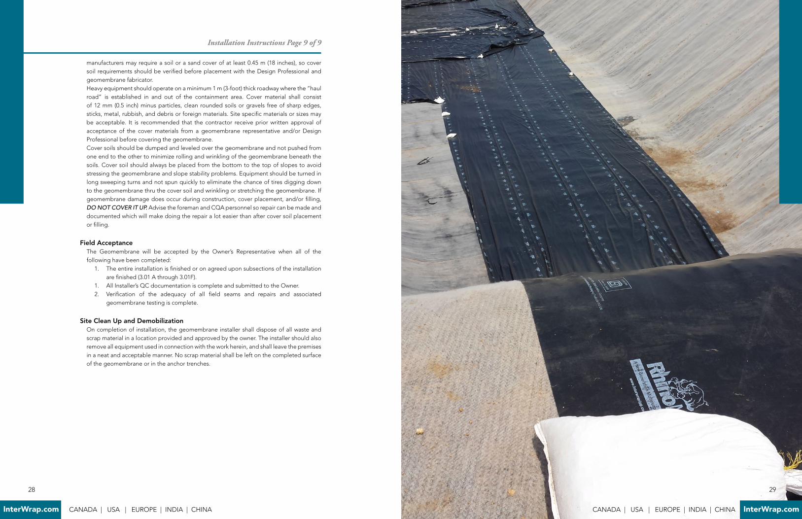
manufacturers may require a soil or a sand cover of at least 0 .45 m (18 inches), so cover soil requirements should be verified before placement with the Design Professional and geomembrane fabricator .Heavy equipment should operate on a minimum 1 m (3-foot) thick roadway where the “haulroad” is established in and out of the containment area . Cover material shall consist of 12 mm (0 .5 inch) minus particles, clean rounded soils or gravels free of sharp edges, sticks, metal, rubbish, and debris or foreign materials . Site specific materials or sizes may be acceptable . It is recommended that the contractor receive prior written approval of acceptance of the cover materials from a geomembrane representative and/or Design Professional before covering the geomembrane .Cover soils should be dumped and leveled over the geomembrane and not pushed from one end to the other to minimize rolling and wrinkling of the geomembrane beneath the soils . Cover soil should always be placed from the bottom to the top of slopes to avoid stressing the geomembrane and slope stability problems . Equipment should be turned in long sweeping turns and not spun quickly to eliminate the chance of tires digging down to the geomembrane thru the cover soil and wrinkling or stretching the geomembrane . If geomembrane damage does occur during construction, cover placement, and/or filling, DO NOT COVER IT UP. Advise the foreman and CQA personnel so repair can be made and documented which will make doing the repair a lot easier than after cover soil placement or filling .
Field AcceptanceThe Geomembrane will be accepted by the Owner’s Representative when all of the following have been completed:
1 . The entire installation is finished or on agreed upon subsections of the installation are finished (3 .01 A through 3 .01F) .
1 . All Installer’s QC documentation is complete and submitted to the Owner .2 . Verification of the adequacy of all field seams and repairs and associated
geomembrane testing is complete .
Site Clean Up and DemobilizationOn completion of installation, the geomembrane installer shall dispose of all waste and scrap material in a location provided and approved by the owner . The installer should also remove all equipment used in connection with the work herein, and shall leave the premises in a neat and acceptable manner . No scrap material shall be left on the completed surface of the geomembrane or in the anchor trenches .
Installation Instructions Page 9 of 9
28
InterWrap.com CANADA | USA | EUROPE | INDIA | CHINA
INTERWRAP FAMILY OF PRODUCTS
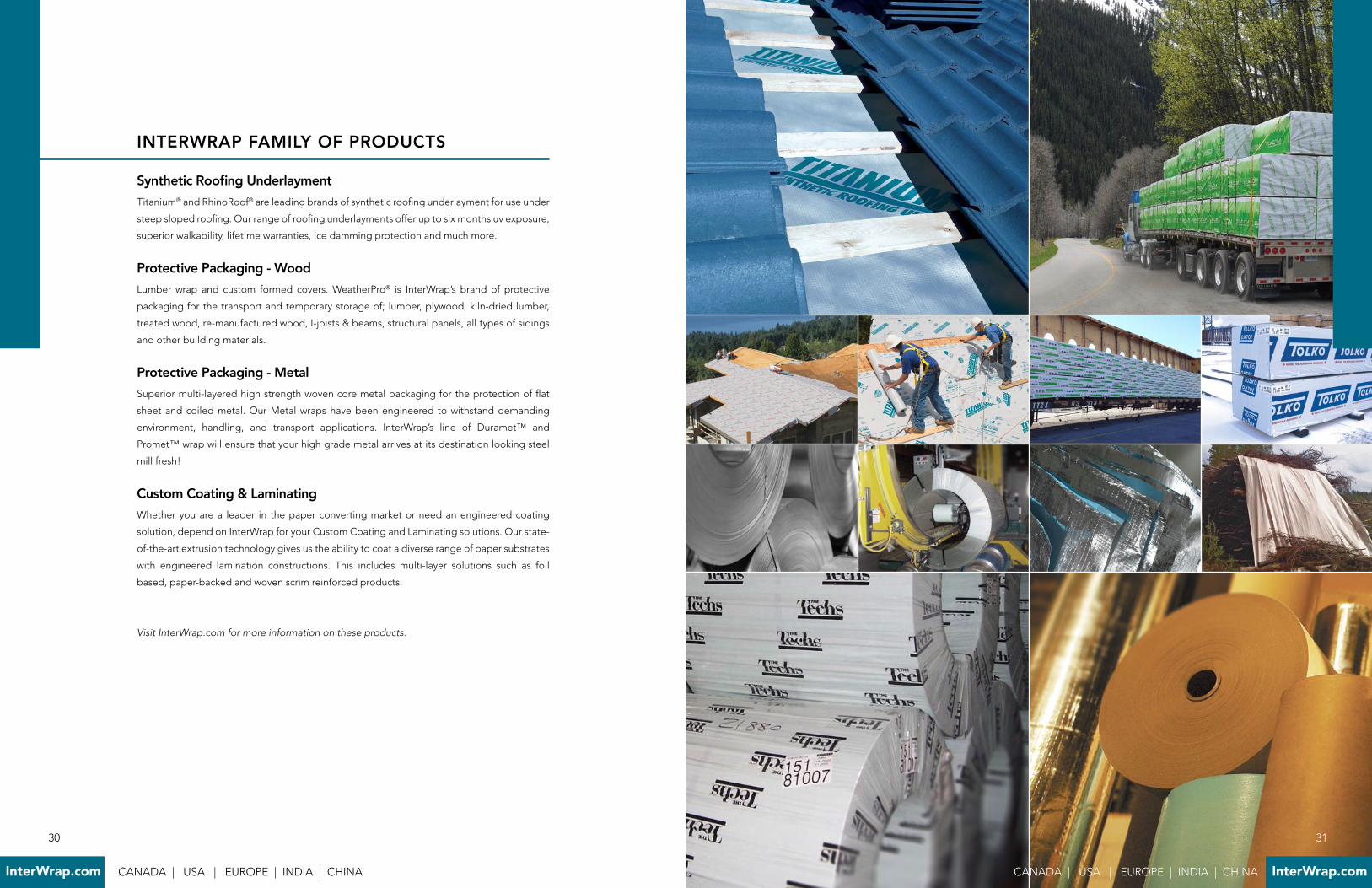
Synthetic Roofing Underlayment
Titanium® and RhinoRoof® are leading brands of synthetic roofing underlayment for use under
steep sloped roofing . Our range of roofing underlayments offer up to six months uv exposure,
superior walkability, lifetime warranties, ice damming protection and much more .
Protective Packaging - Wood
Lumber wrap and custom formed covers . WeatherPro® is InterWrap’s brand of protective
packaging for the transport and temporary storage of; lumber, plywood, kiln-dried lumber,
treated wood, re-manufactured wood, I-joists & beams, structural panels, all types of sidings
and other building materials .
Protective Packaging - Metal
Superior multi-layered high strength woven core metal packaging for the protection of flat
sheet and coiled metal . Our Metal wraps have been engineered to withstand demanding
environment, handling, and transport applications . InterWrap’s line of Duramet™ and
Promet™ wrap will ensure that your high grade metal arrives at its destination looking steel
mill fresh!
Custom Coating & Laminating
Whether you are a leader in the paper converting market or need an engineered coating
solution, depend on InterWrap for your Custom Coating and Laminating solutions . Our state-
of-the-art extrusion technology gives us the ability to coat a diverse range of paper substrates
with engineered lamination constructions . This includes multi-layer solutions such as foil
based, paper-backed and woven scrim reinforced products .
Visit InterWrap.com for more information on these products.
31
CANADA | USA | EUROPE | INDIA | CHINA InterWrap.com
30
InterWrap.com CANADA | USA | EUROPE | INDIA | CHINA
33
CANADA | USA | EUROPE | INDIA | CHINA InterWrap.com
ISO 9001:2008 ISO 14001:2004
32
InterWrap.com CANADA | USA | EUROPE | INDIA | CHINA

ISO 18001:2007
Sales - North America & Europe:
Clive Mills - Director
Cell: +1 262 389 0695
Email: cmills@interwrap .com
Jimmie Eloff
Cell: +1 765 414 7285
Email: jeloff@interwrap .com
Tom Liberator
Cell: +1 503 789 7178
Email: tliberator@interwrap .com
Sales - India & Asia:
Neil Mukharji
Tel: +91 22 67416620 / 60 / 00
Cell: +91 9920958886
Email: nmukharji@interwrap .com
Technical Support:
Manish Khedkar
Email: mkhedkar@interwrap .com
Head Office:
1818 - 1177 West Hastings Street
Vancouver BC, Canada V6E 2K3
Toll Free: 1-800-567-9727
Telephone: 1-778-945-2888
Fax: 1-604-696-5518
Email: info@interwrap .com
KEY CONTACTS
35
CANADA | USA | EUROPE | INDIA | CHINA InterWrap.com
34
InterWrap.com CANADA | USA | EUROPE | INDIA | CHINA


