58
Industrial Generator Sets Models: 200REOZPB 230--300REOZDB 350/400REOZD 350/400REOZDC 450REOZDB Controllers: Decision-Makert550 Decision-Makert3+, 16-Light TP-6338 9/07e Wiring Diagrams
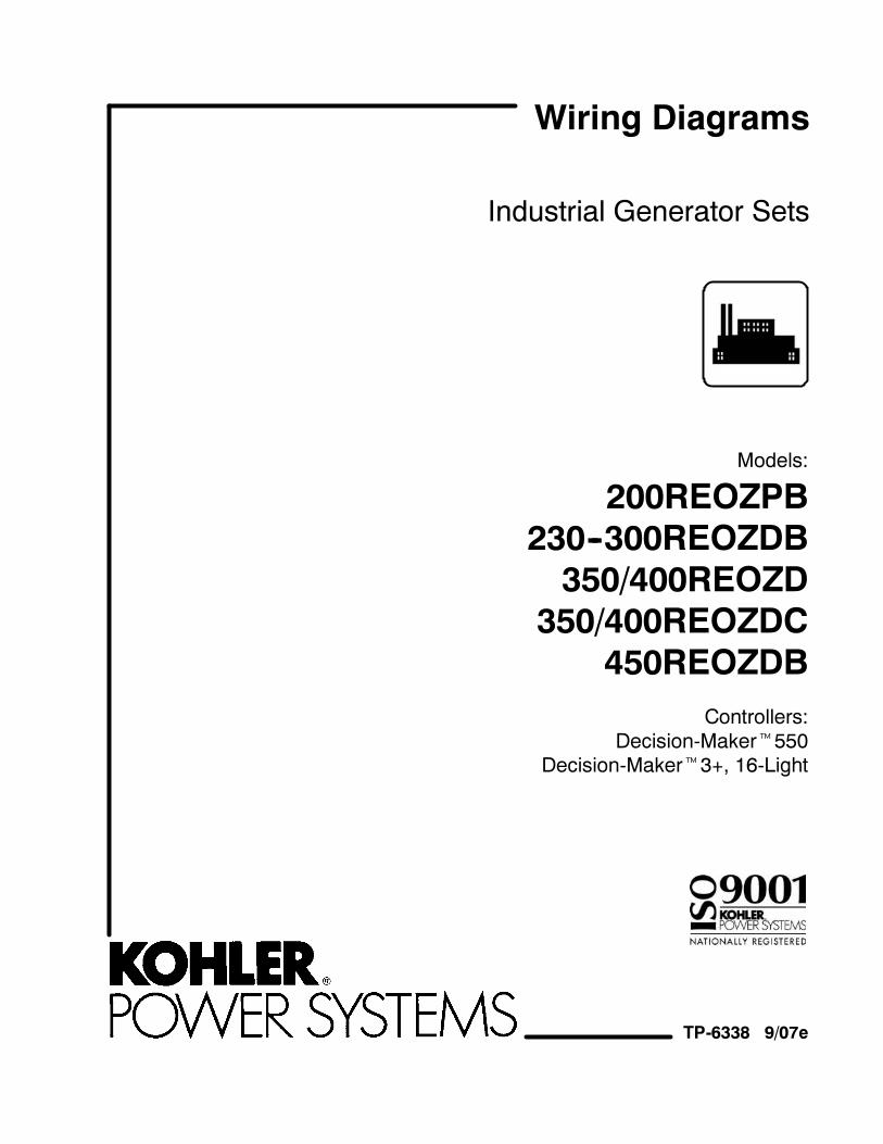
Industrial Generator Sets
Models:
200REOZPB
230--300REOZDB
350/400REOZD
350/400REOZDC
450REOZDB
Controllers:
Decision-Maker�550Decision-Maker�3+, 16-Light
TP-6338 9/07e
Wiring Diagrams
Product Identification Information
Product identification numbers determine service parts.Record the product identification numbers in the spacesbelow immediately after unpacking the products so thatthe numbers are readily available for future reference.Record field-installed kit numbers after installing thekits.
Generator Set Identification Numbers
Record the product identification numbers from thegenerator set nameplate(s).
Model Designation
Specification Number
Serial Number
Accessory Number Accessory Description
Controller Identification
Record the controller description from the generator setoperation manual, spec sheet, or sales invoice.
Controller Description
Engine Identification
Record the product identification information from theengine nameplate.
Manufacturer
Model Designation
Serial Number
TP-6338 9/07 3Introduction
Introduction
This manual provides wiring diagrams for the Detroit
Diesel-powered generator sets listed on the front cover,
equipped with one of the following controllers:
� Decision-Maker�550
� Decision-Maker�3+, 16-Light
Information in this publication represents data available
at the time of print. Kohler Co. reserves the right to
change this publication and the products represented
without notice and without any obligation or liability
whatsoever.
Service Assistance
For professional advice on generator set power
requirements and conscientious service, please contact
your nearest Kohler distributor or dealer.
� Consult the Yellow Pages under the heading
Generators—Electric.
� Visit the Kohler Power Systems website at
KohlerPower.com.
� Look at the labels and stickers on your Kohler product
or review the appropriate literature or documents
included with the product.
� Call toll free in the US and Canada 1-800-544-2444.
� Outside the US andCanada, call the nearest regional
office.
Headquarters Europe, Middle East, Africa
(EMEA)
Kohler Power Systems
ZI Senia 122
12, rue des Hauts Flouviers
94517 Thiais Cedex
France
Phone: (33) 1 41 735500
Fax: (33) 1 41 735501
Asia Pacific
Power Systems Asia Pacific Regional Office
Singapore, Republic of Singapore
Phone: (65) 6264-6422
Fax: (65) 6264-6455
China
North China Regional Office, Beijing
Phone: (86) 10 6518 7950
(86) 10 6518 7951
(86) 10 6518 7952
Fax: (86) 10 6518 7955
East China Regional Office, Shanghai
Phone: (86) 21 6288 0500
Fax: (86) 21 6288 0550
India, Bangladesh, Sri Lanka
India Regional Office
Bangalore, India
Phone: (91) 80 3366208
(91) 80 3366231
Fax: (91) 80 3315972
Japan, Korea
North Asia Regional Office
Tokyo, Japan
Phone: (813) 3440-4515
Fax: (813) 3440-2727
Latin America
Latin America Regional Office
Lakeland, Florida, USA
Phone: (863) 619-7568
Fax: (863) 701-7131
TP-6338 9/074 Wiring Diagrams
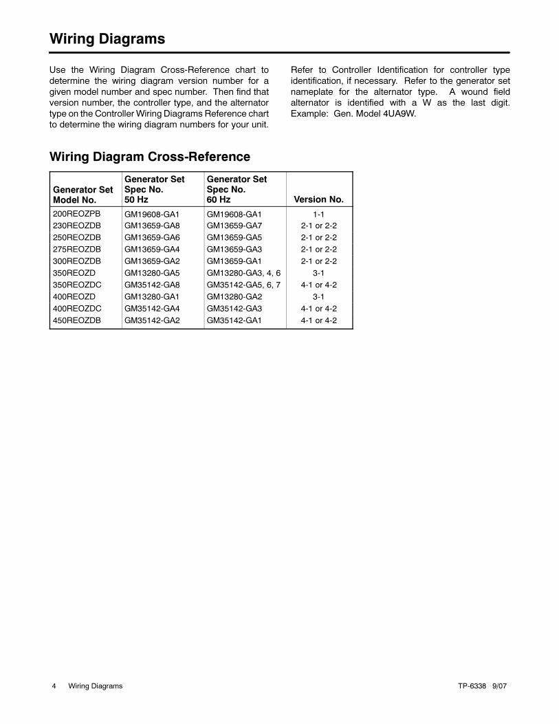
Wiring Diagrams
Use the Wiring Diagram Cross-Reference chart to
determine the wiring diagram version number for a
given model number and spec number. Then find that
version number, the controller type, and the alternator
type on the Controller Wiring Diagrams Reference chart
to determine the wiring diagram numbers for your unit.
Refer to Controller Identification for controller type
identification, if necessary. Refer to the generator set
nameplate for the alternator type. A wound field
alternator is identified with a W as the last digit.
Example: Gen. Model 4UA9W.
Wiring Diagram Cross-Reference
Generator SetModel No.
Generator SetSpec No.50 Hz
Generator SetSpec No.60 Hz Version No.
200REOZPB GM19608-GA1 GM19608-GA1 1-1
230REOZDB GM13659-GA8 GM13659-GA7 2-1 or 2-2
250REOZDB GM13659-GA6 GM13659-GA5 2-1 or 2-2
275REOZDB GM13659-GA4 GM13659-GA3 2-1 or 2-2
300REOZDB GM13659-GA2 GM13659-GA1 2-1 or 2-2
350REOZD GM13280-GA5 GM13280-GA3, 4, 6 3-1
350REOZDC GM35142-GA8 GM35142-GA5, 6, 7 4-1 or 4-2
400REOZD GM13280-GA1 GM13280-GA2 3-1
400REOZDC GM35142-GA4 GM35142-GA3 4-1 or 4-2
450REOZDB GM35142-GA2 GM35142-GA1 4-1 or 4-2
TP-6338 9/07 5Wiring Diagrams
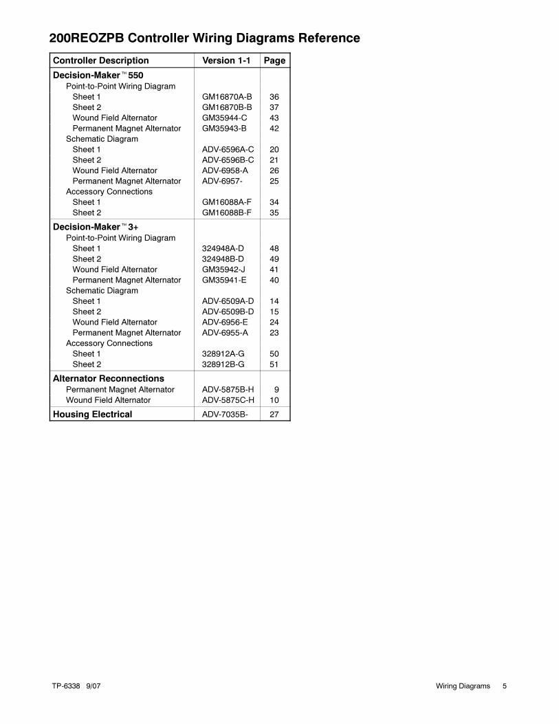
200REOZPB Controller Wiring Diagrams Reference
Controller Description Version 1-1 Page
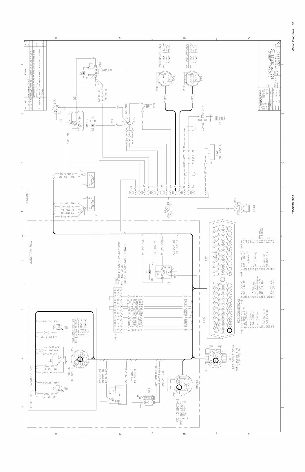
Decision-Maker�550Point-to-Point Wiring Diagram
Sheet 1 GM16870A-B 36
Sheet 2 GM16870B-B 37
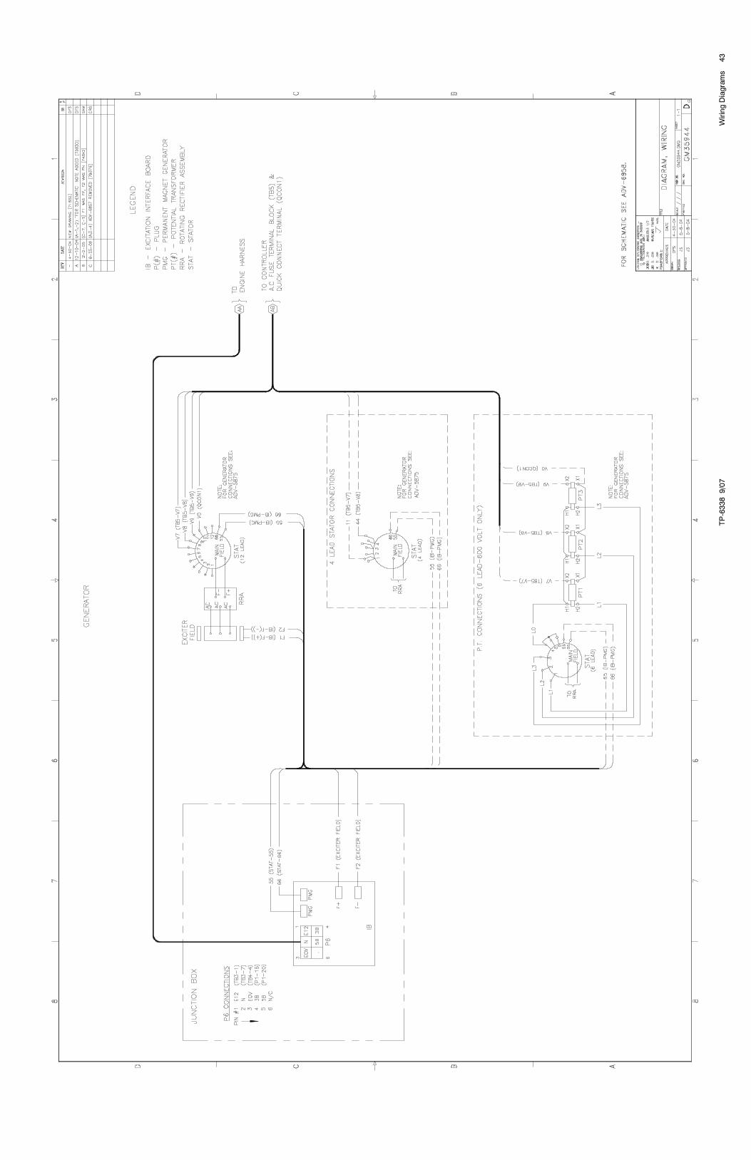
Wound Field Alternator GM35944-C 43
Permanent Magnet Alternator GM35943-B 42
Schematic Diagram
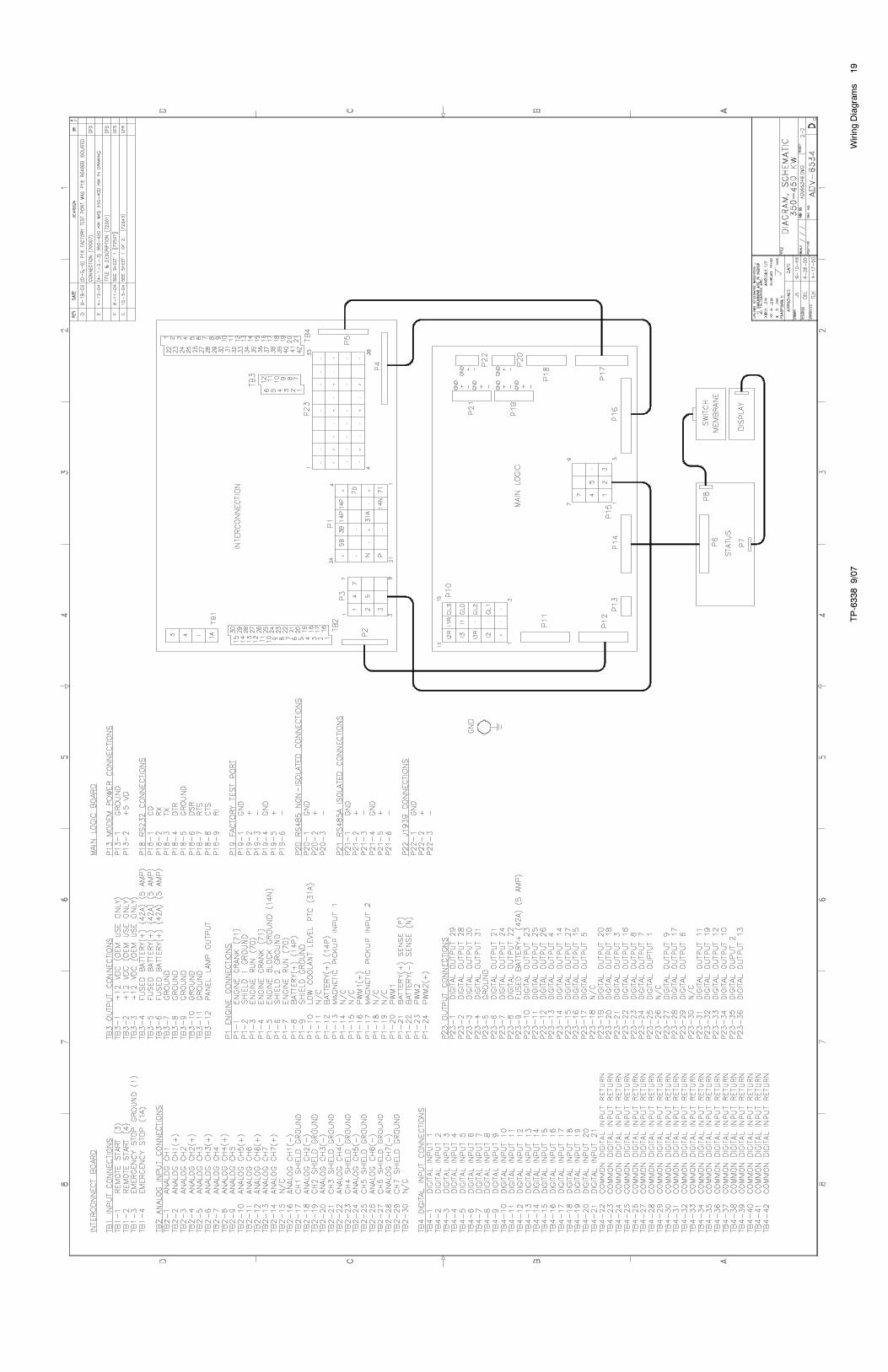
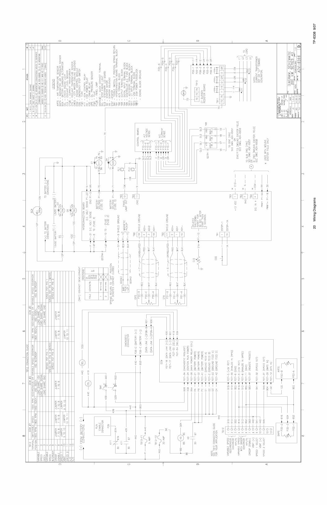
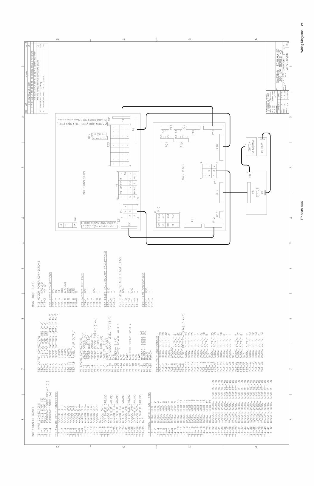
Sheet 1 ADV-6596A-C 20
Sheet 2 ADV-6596B-C 21
Wound Field Alternator ADV-6958-A 26
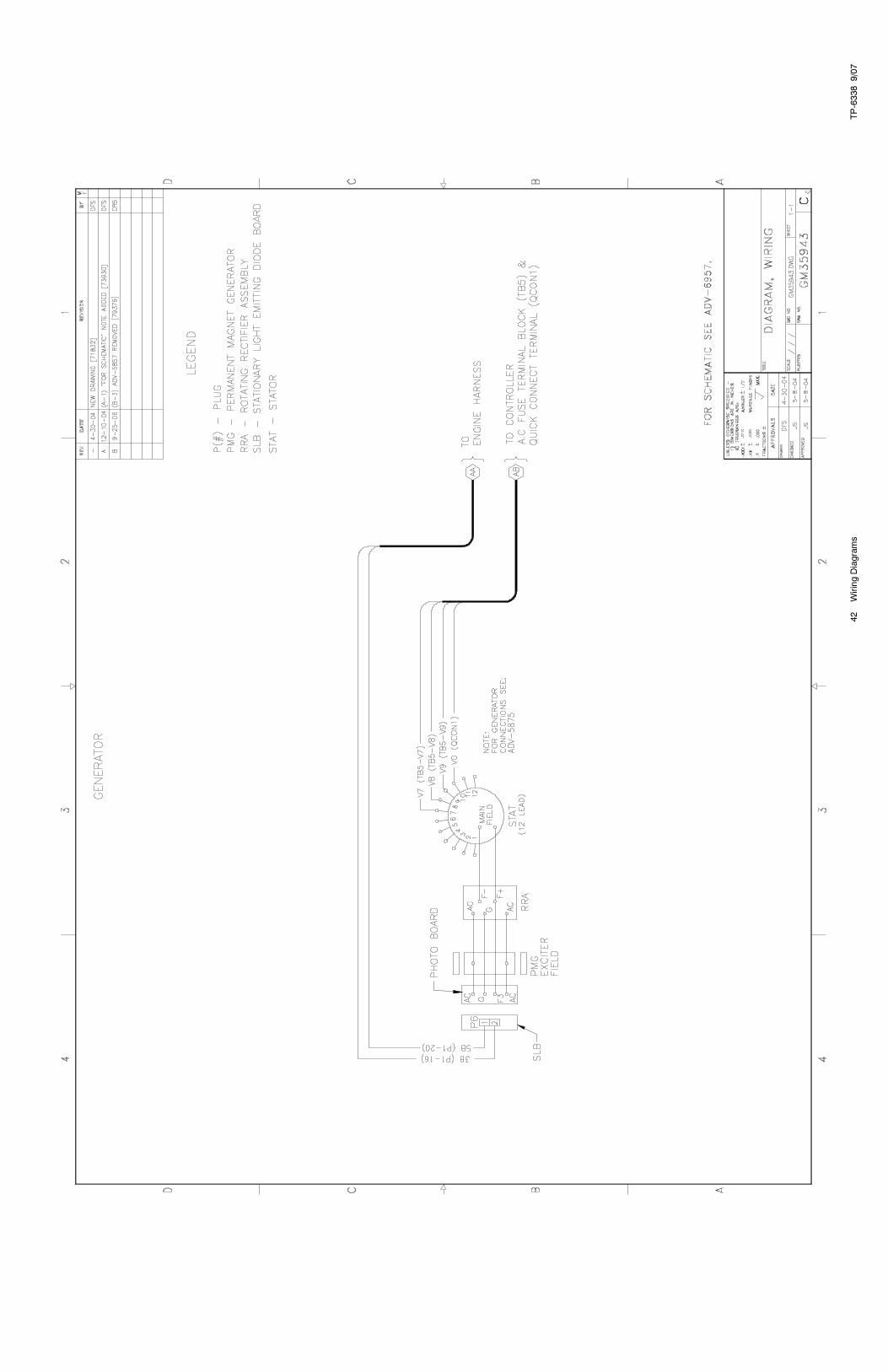
Permanent Magnet Alternator ADV-6957- 25
Accessory Connections
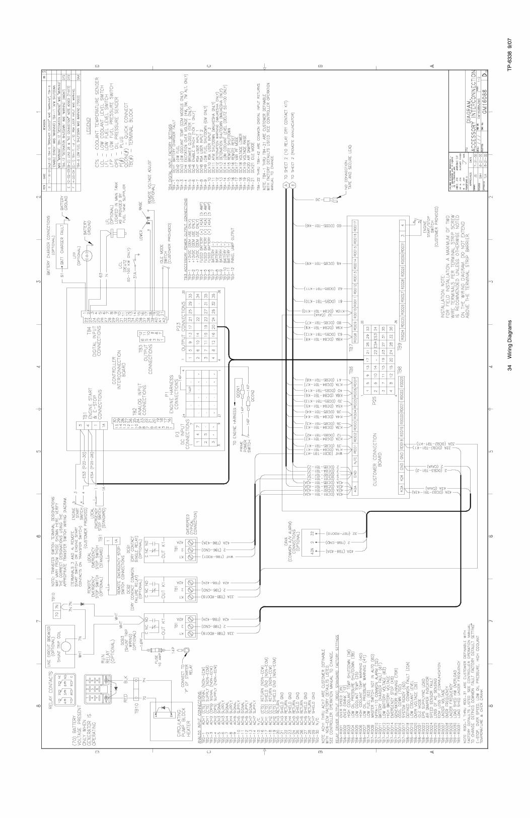
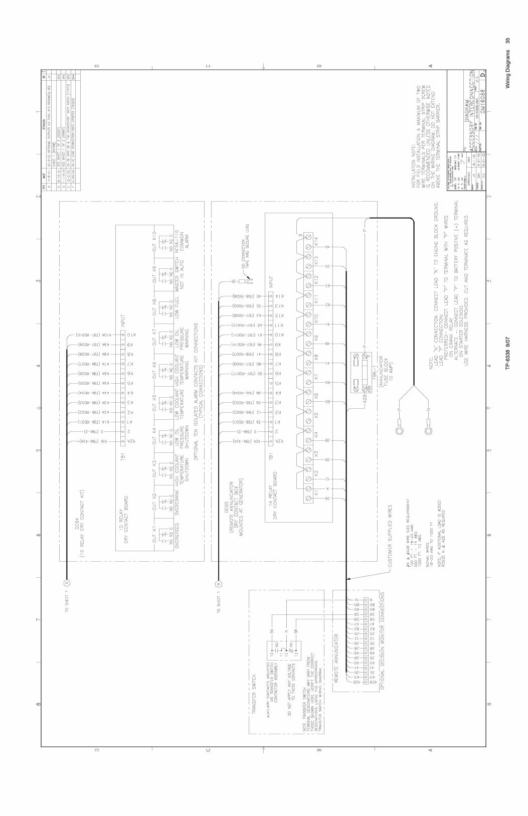
Sheet 1 GM16088A-F 34
Sheet 2 GM16088B-F 35
Decision-Maker�3+Point-to-Point Wiring Diagram
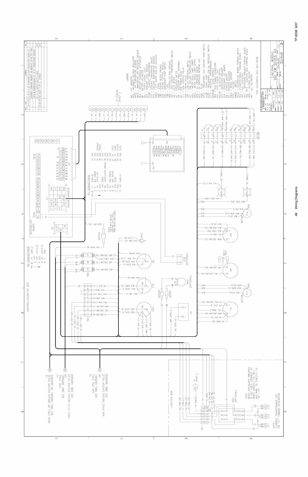
Sheet 1 324948A-D 48
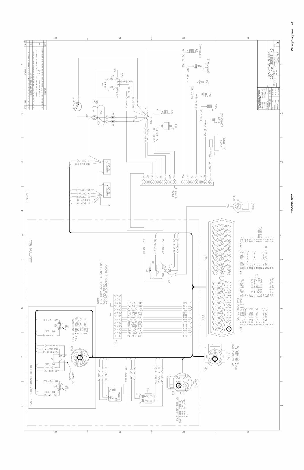
Sheet 2 324948B-D 49
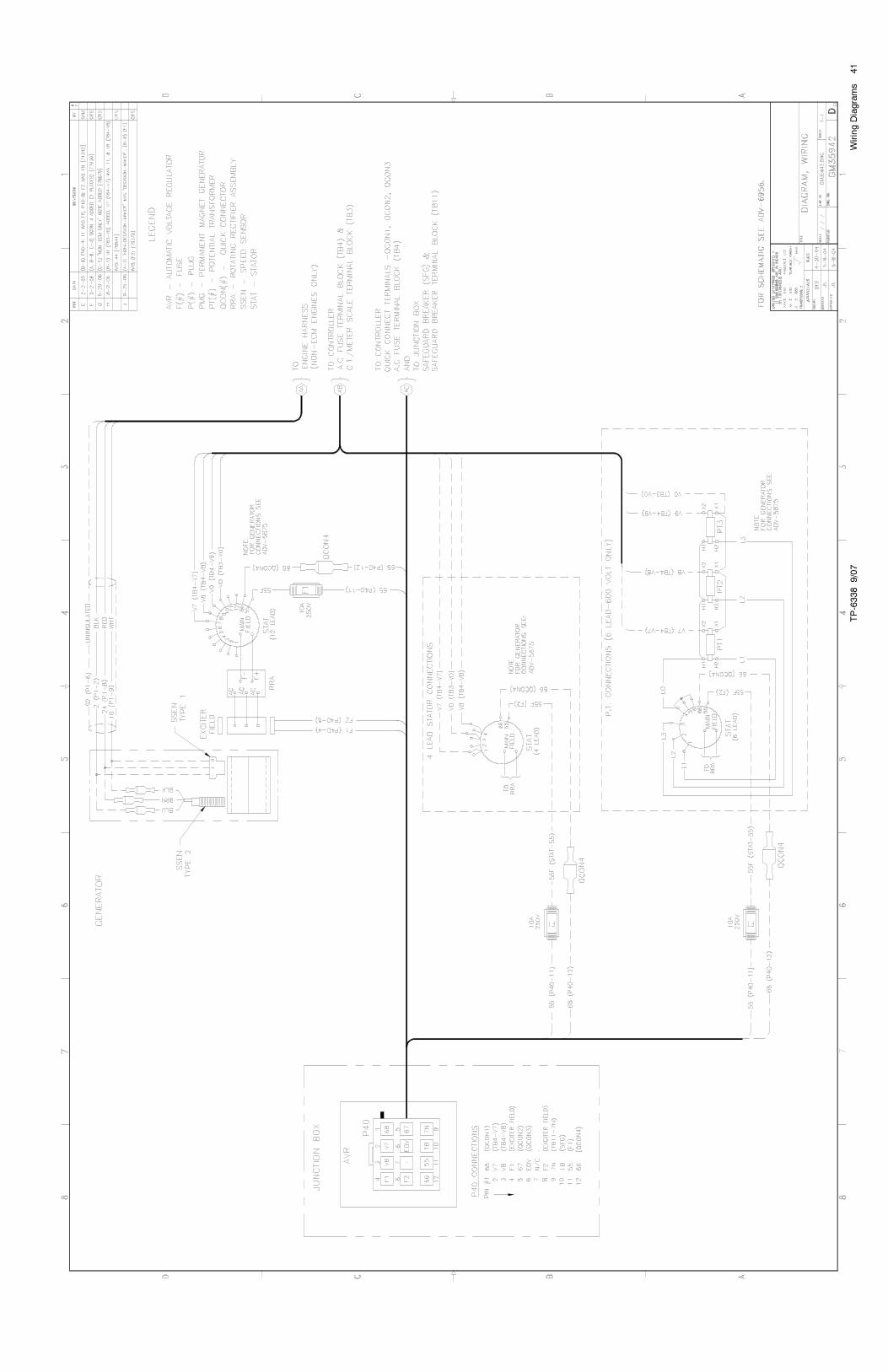
Wound Field Alternator GM35942-J 41
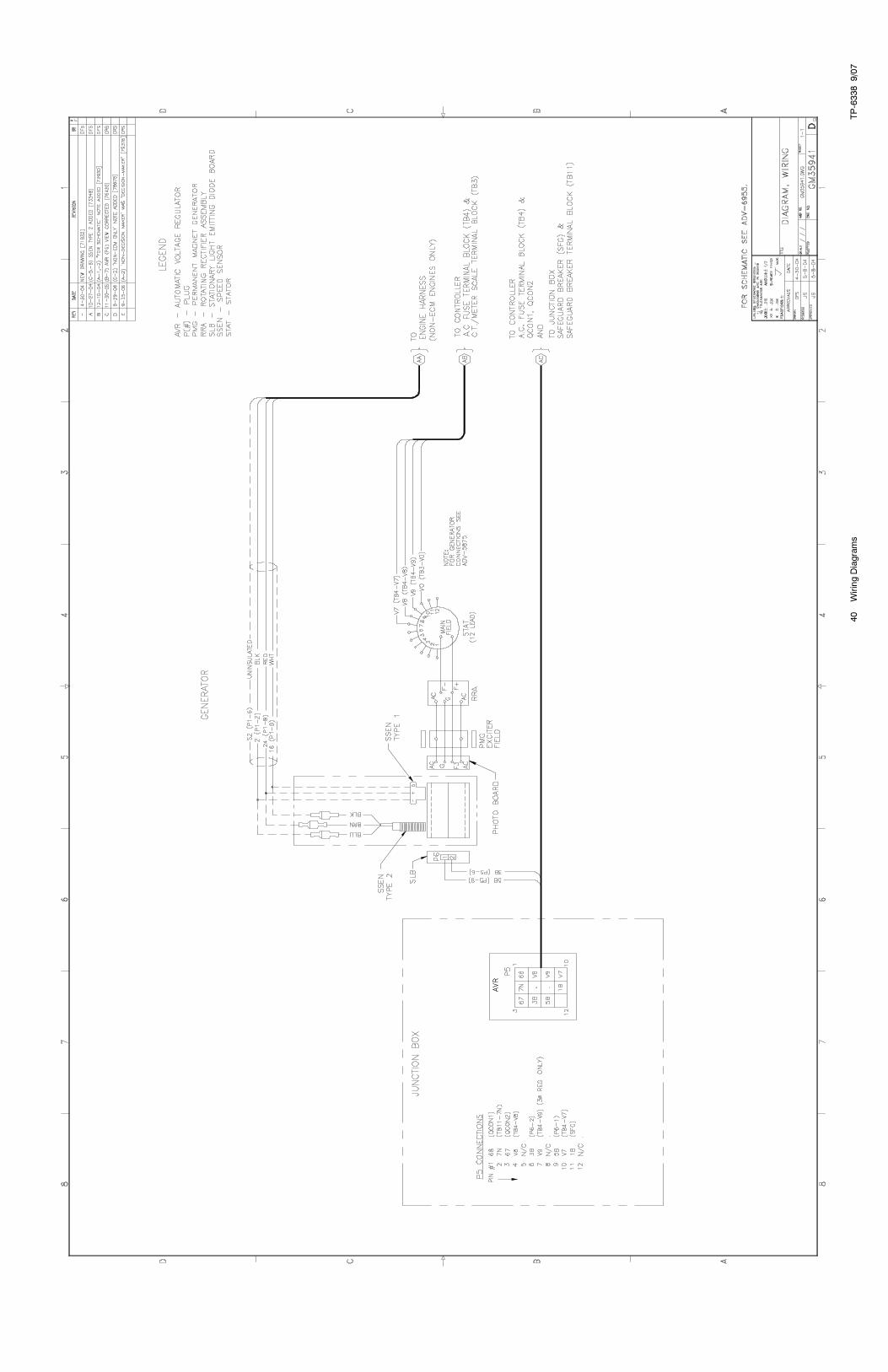
Permanent Magnet Alternator GM35941-E 40
Schematic Diagram
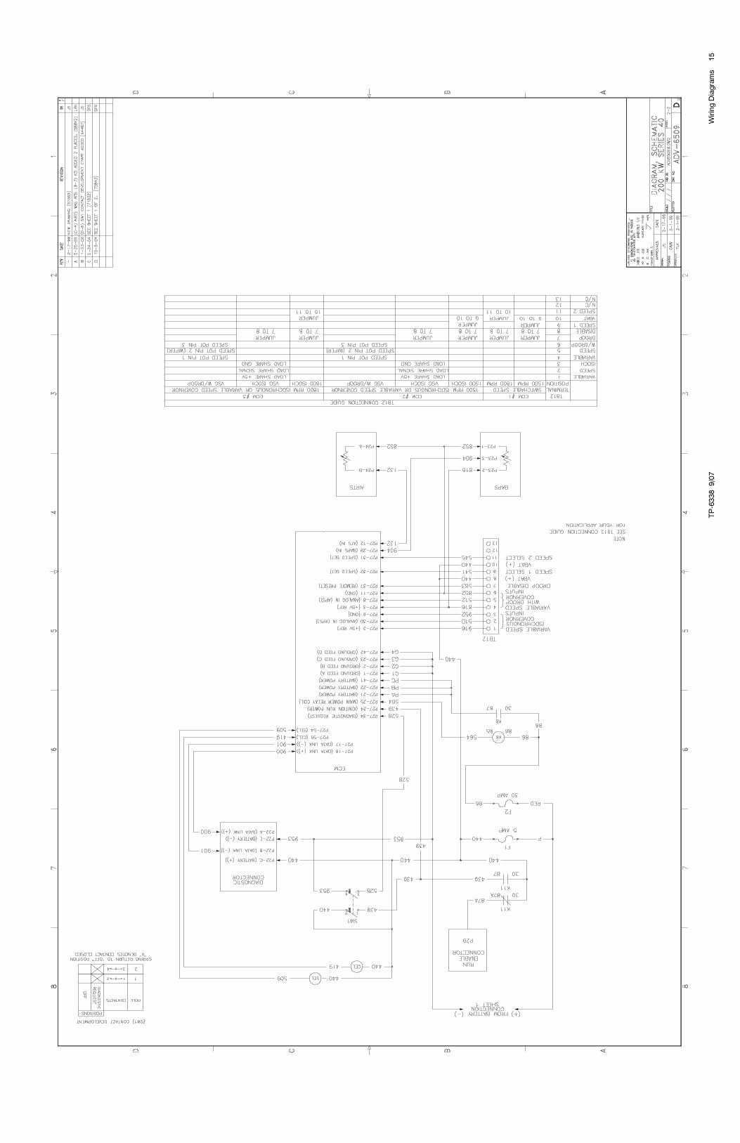
Sheet 1 ADV-6509A-D 14
Sheet 2 ADV-6509B-D 15
Wound Field Alternator ADV-6956-E 24
Permanent Magnet Alternator ADV-6955-A 23
Accessory Connections
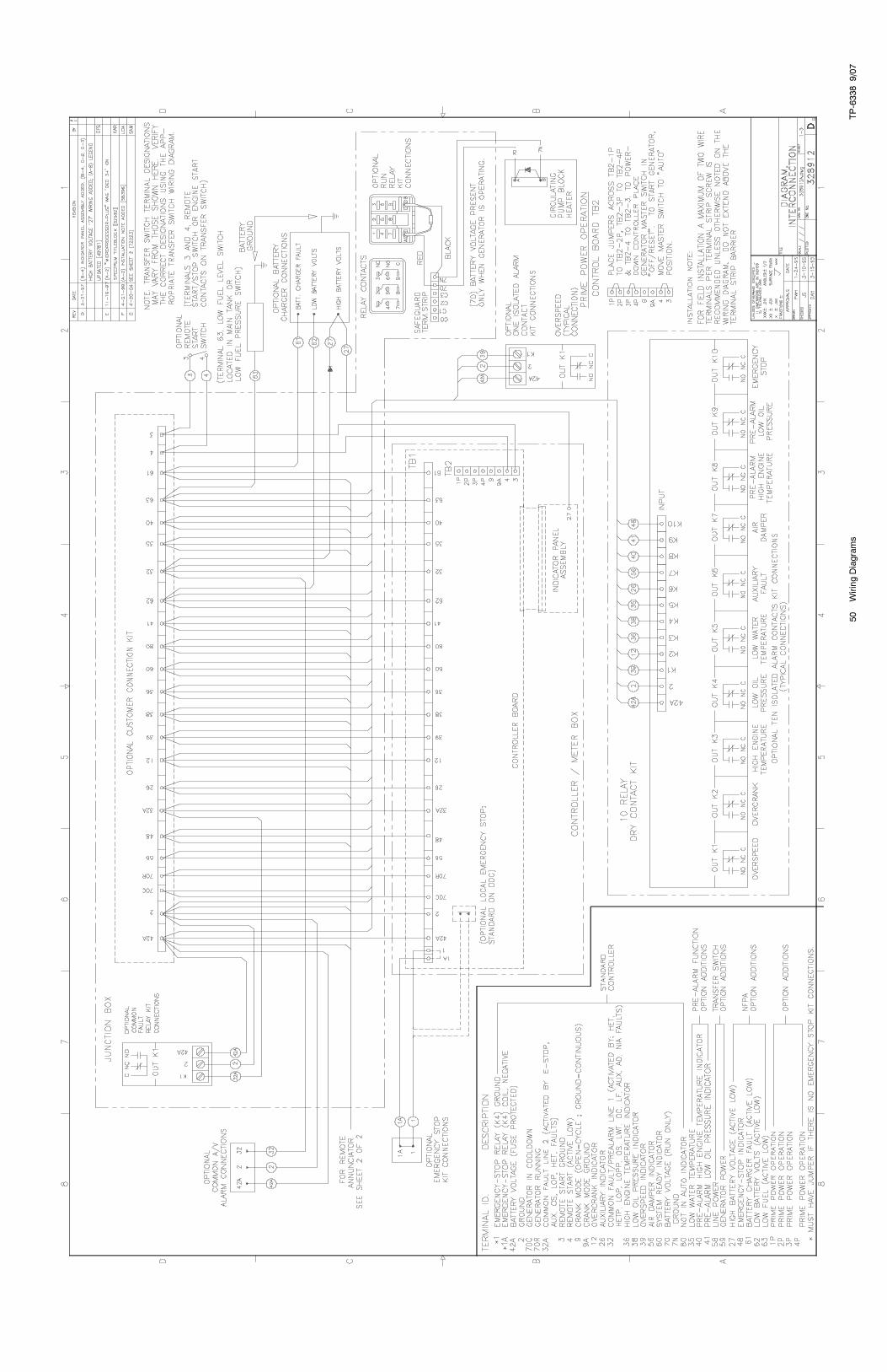
Sheet 1 328912A-G 50
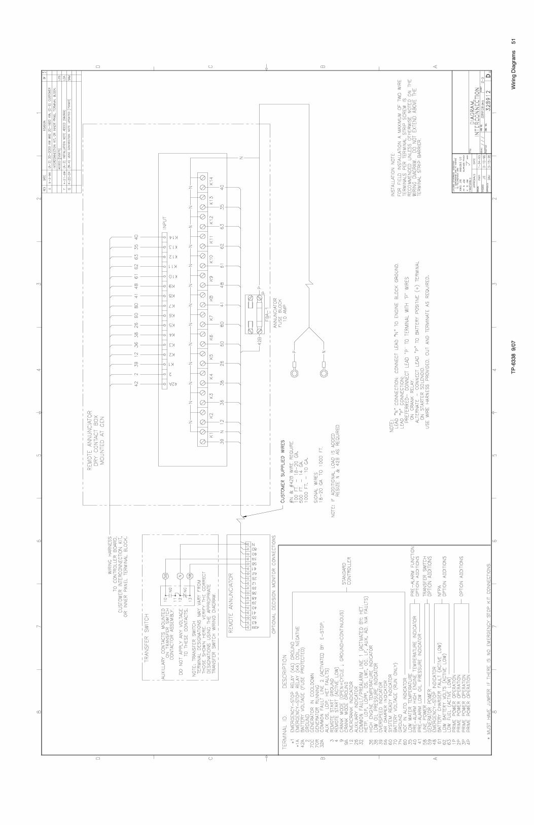
Sheet 2 328912B-G 51
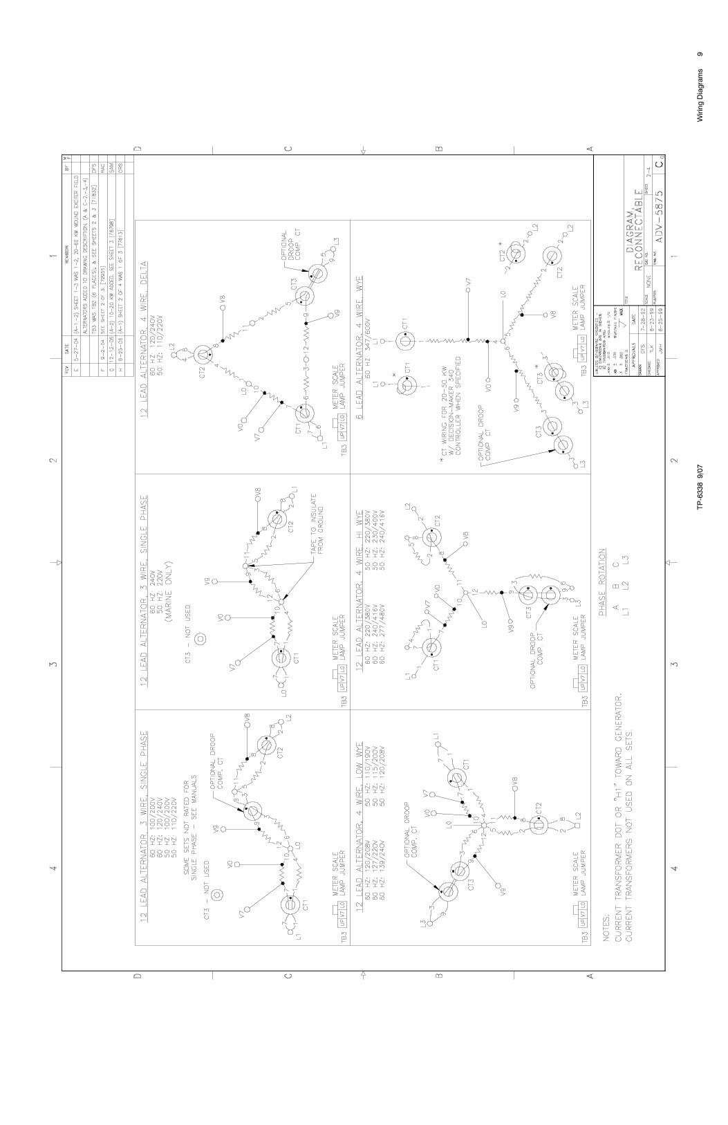
Alternator ReconnectionsPermanent Magnet Alternator ADV-5875B-H 9
Wound Field Alternator ADV-5875C-H 10
Housing Electrical ADV-7035B- 27
TP-6338 9/076 Wiring Diagrams
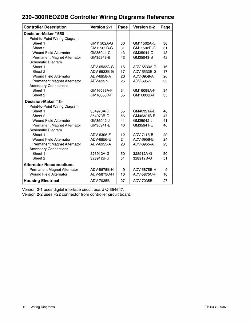
230--300REOZDB Controller Wiring Diagrams Reference
Controller Description Version 2-1 Page Version 2-2 Page
Decision-Maker�550Point-to-Point Wiring Diagram
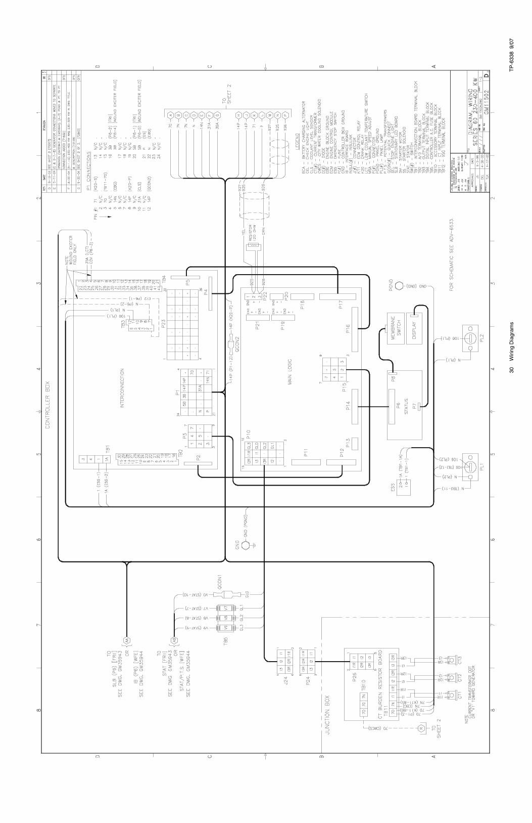
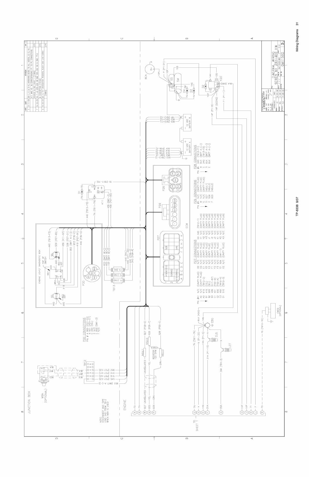
Sheet 1 GM11502A-G 30 GM11502A-G 30
Sheet 2 GM11502B-G 31 GM11502B-G 31
Wound Field Alternator GM35944-C 43 GM35944-C 43
Permanent Magnet Alternator GM35943-B 42 GM35943-B 42
Schematic Diagram
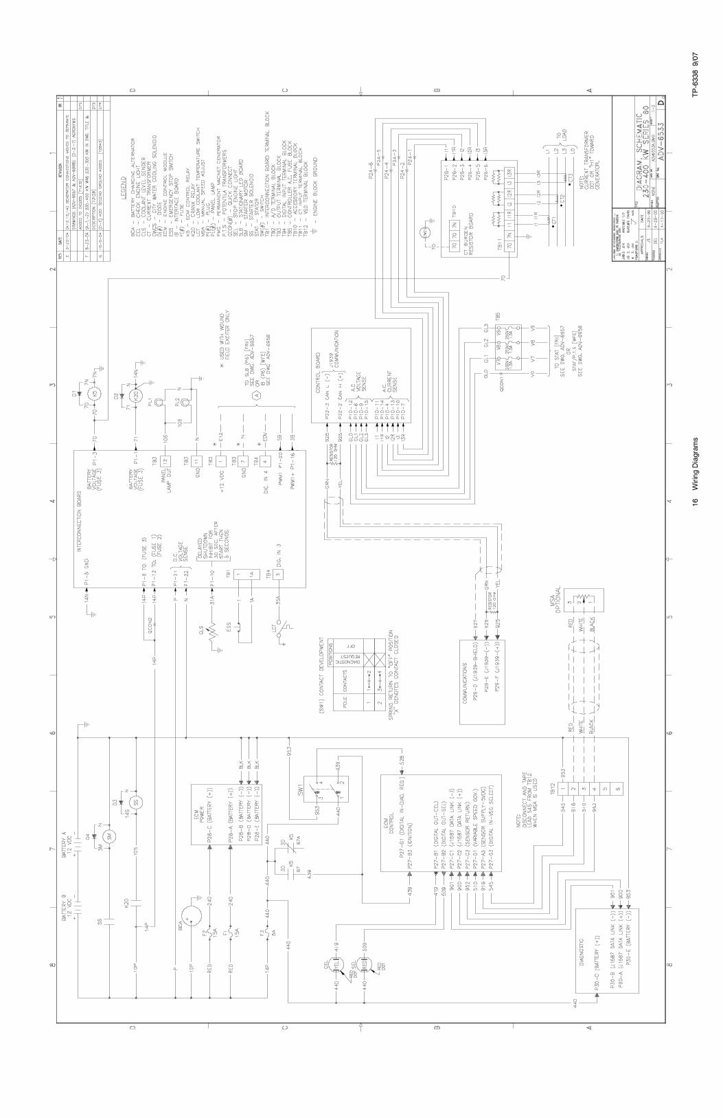
Sheet 1 ADV-6533A-G 16 ADV-6533A-G 16
Sheet 2 ADV-6533B-G 17 ADV-6533B-G 17
Wound Field Alternator ADV-6958-A 26 ADV-6958-A 26
Permanent Magnet Alternator ADV-6957- 25 ADV-6957- 25
Accessory Connections
Sheet 1 GM16088A-F 34 GM16088A-F 34
Sheet 2 GM16088B-F 35 GM16088B-F 35
Decision-Maker�3+Point-to-Point Wiring Diagram
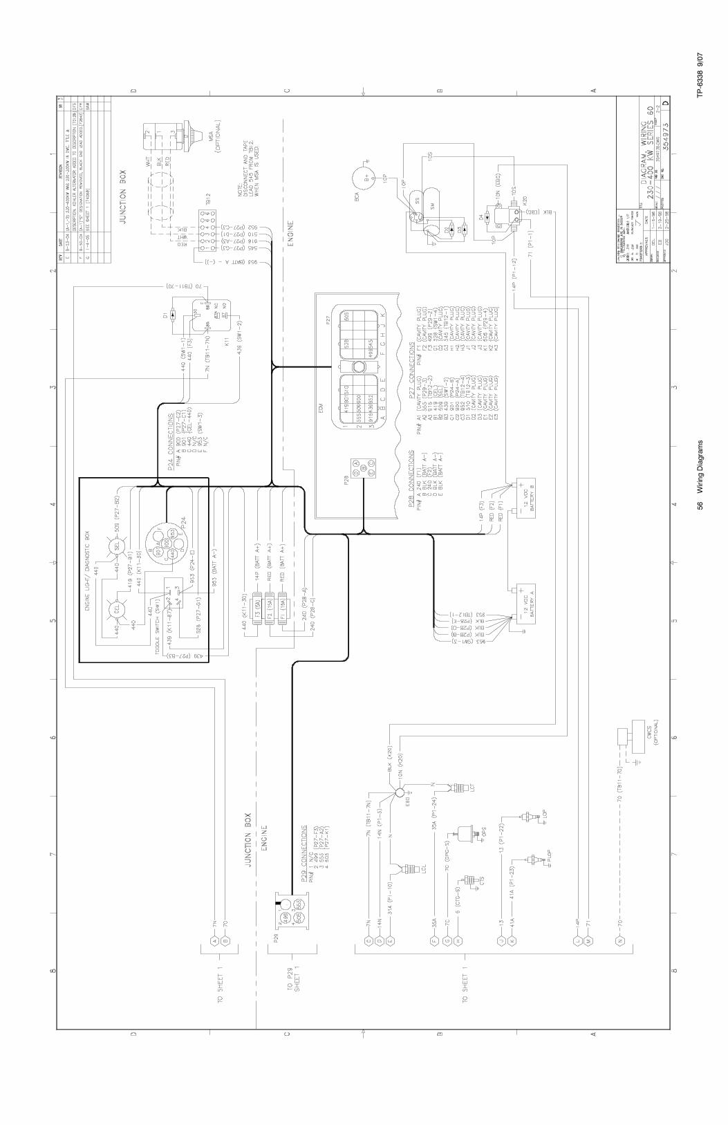
Sheet 1 354973A-G 55 GM46321A-B 46
Sheet 2 354973B-G 56 GM46321B-B 47
Wound Field Alternator GM35942-J 41 GM35942-J 41
Permanent Magnet Alternator GM35941-E 40 GM35941-E 40
Schematic Diagram
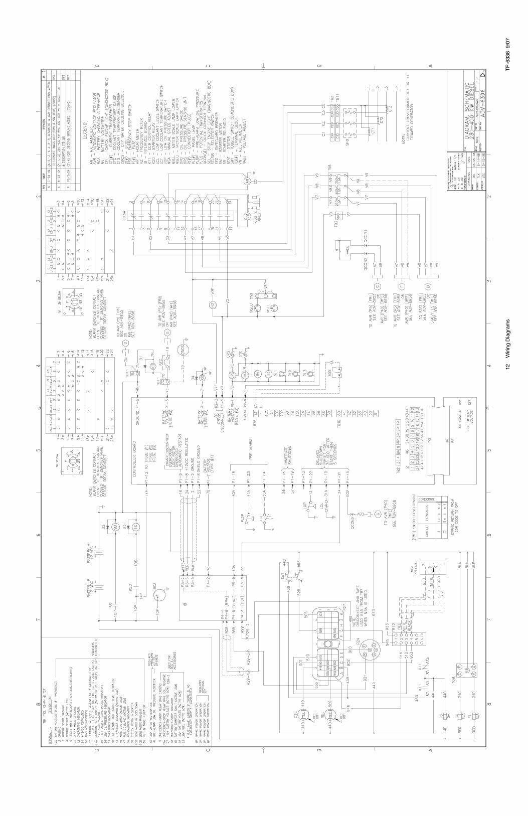
Sheet 1 ADV-6396-F 12 ADV-7116-B 29
Wound Field Alternator ADV-6956-E 24 ADV-6956-E 24
Permanent Magnet Alternator ADV-6955-A 23 ADV-6955-A 23
Accessory Connections
Sheet 1 328912A-G 50 328912A-G 50
Sheet 2 328912B-G 51 328912B-G 51
Alternator ReconnectionsPermanent Magnet Alternator ADV-5875B-H 9 ADV-5875B-H 9
Wound Field Alternator ADV-5875C-H 10 ADV-5875C-H 10
Housing Electrical ADV-7035B- 27 ADV-7035B- 27
Version 2-1 uses digital interface circuit board C-354647.
Version 2-2 uses P22 connector from controller circuit board.

TP-6338 9/07 7Wiring Diagrams
350/400REOZD Controller Wiring Diagrams Reference
Controller Description Version 3-1 Page
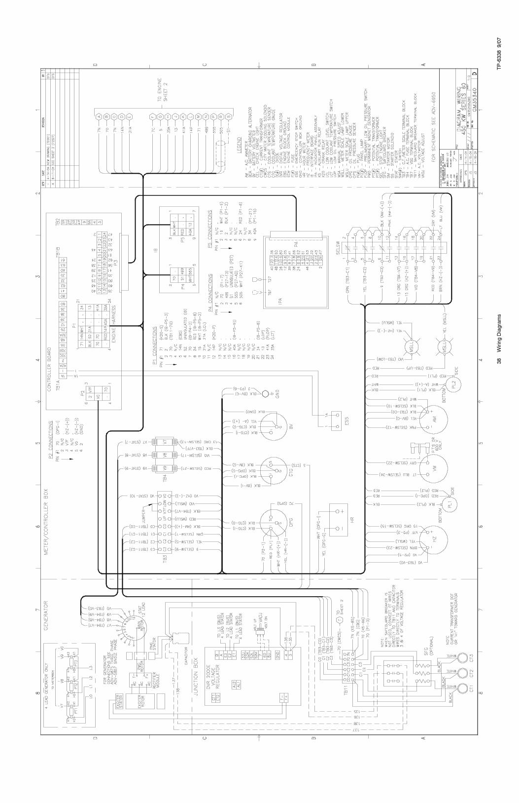
Decision-Maker�550Point-to-Point Wiring Diagram
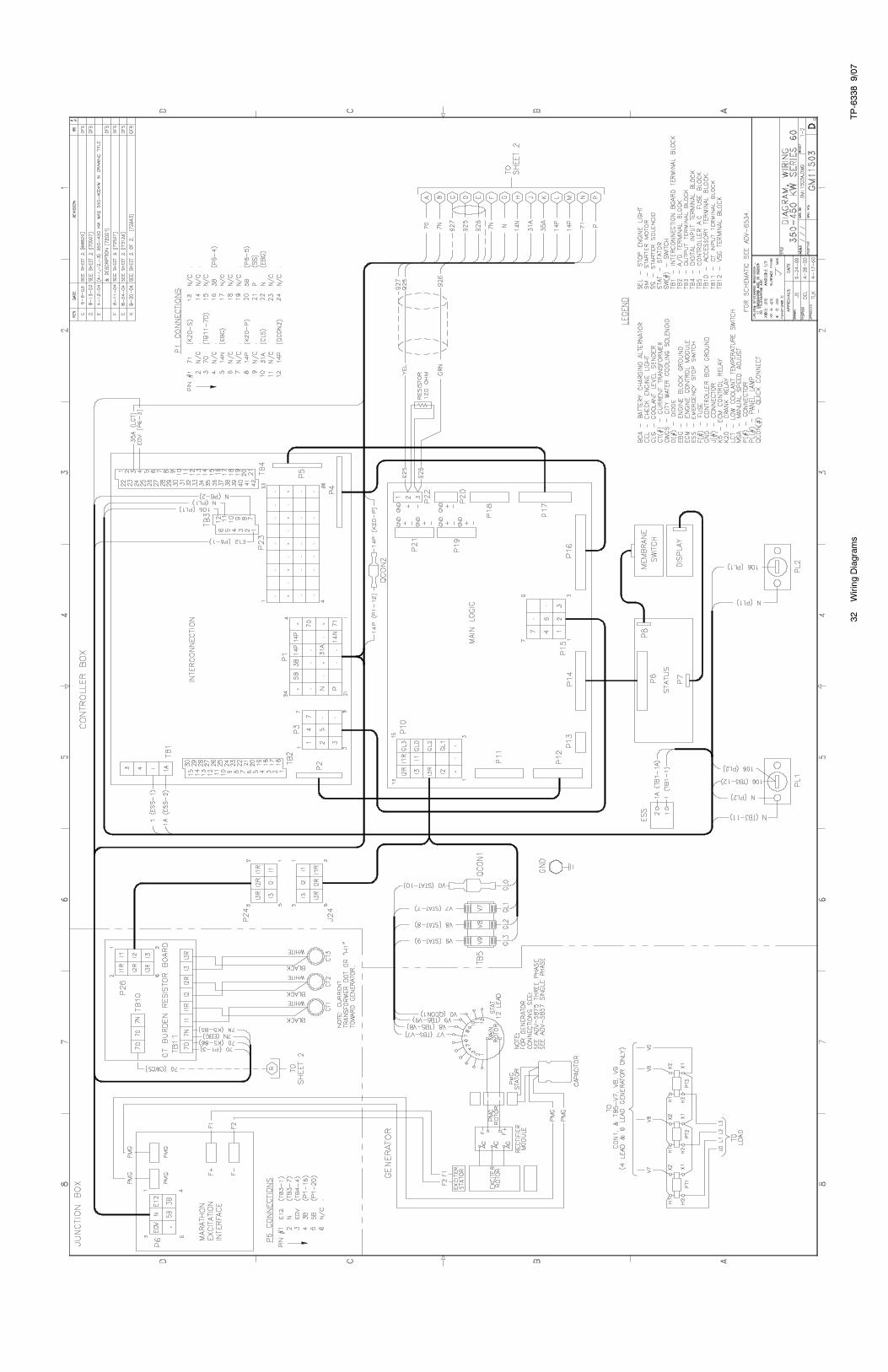
Sheet 1 GM11503A-H 32
Sheet 2 GM11503B-H 33
Schematic Diagram
Sheet 1 ADV-6534A-G 18
Sheet 2 ADV-6534B-G 19
Accessory Connections
Sheet 1 GM16088A-F 34
Sheet 2 GM16088B-F 35
Decision-Maker�3+Point-to-Point Wiring Diagram
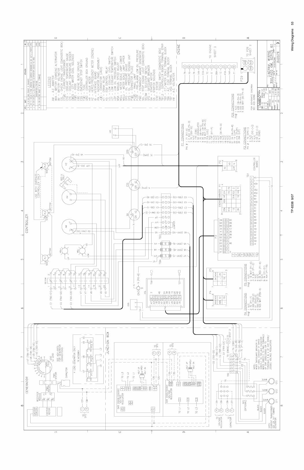
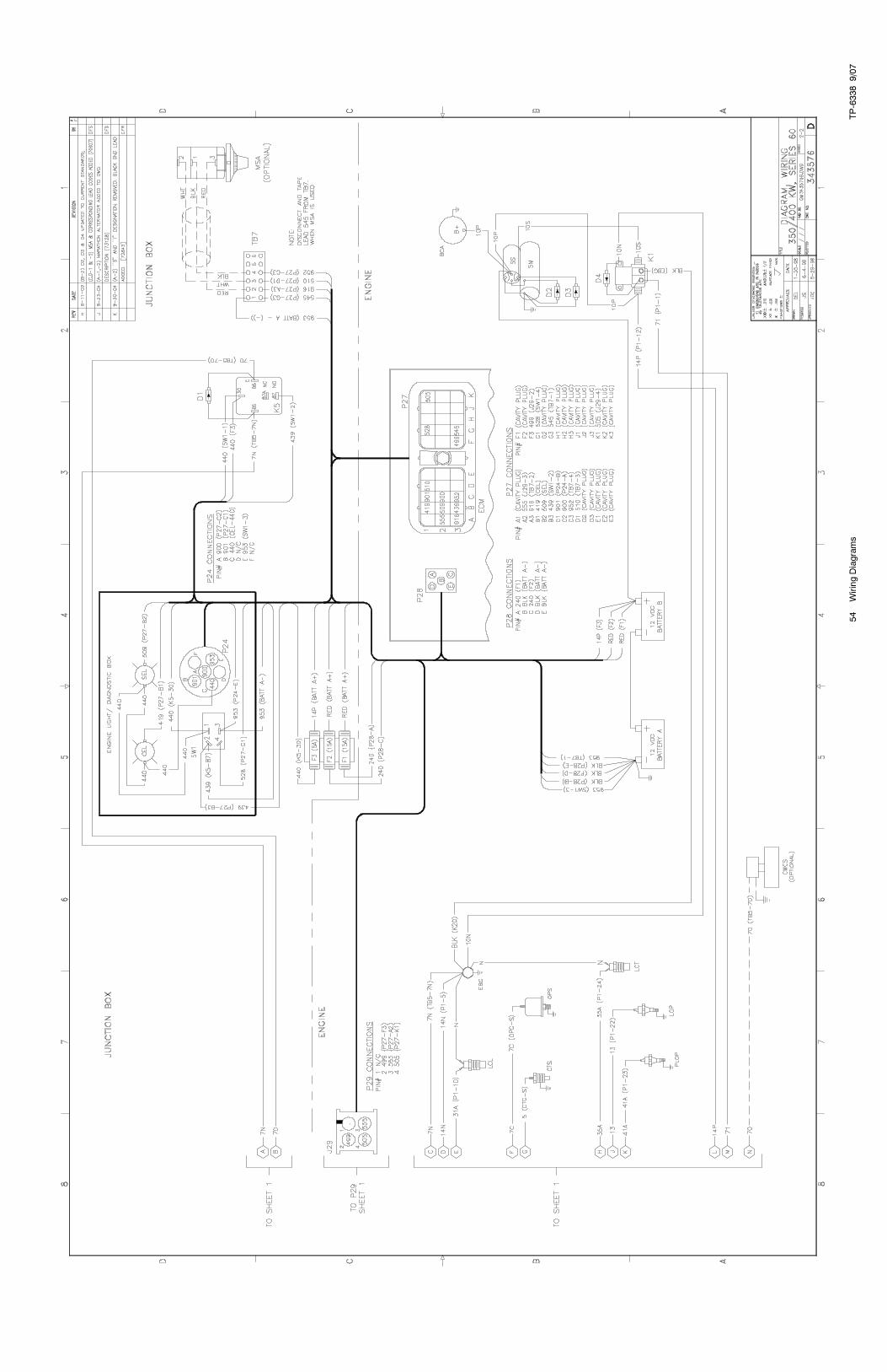
Sheet 1 343576A-K 53
Sheet 2 343576B-K 54
Schematic Diagram
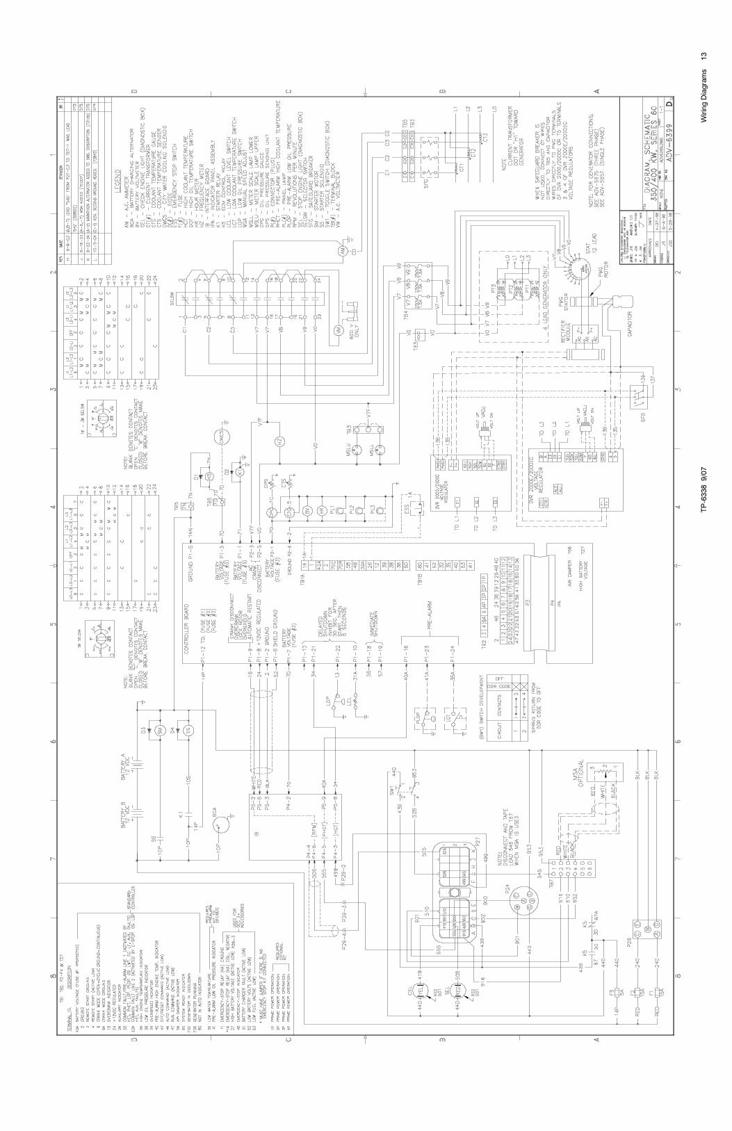
Sheet 1 ADV-6399-L 13
Accessory Connections
Sheet 1 328912A-G 50
Sheet 2 328912B-G 51
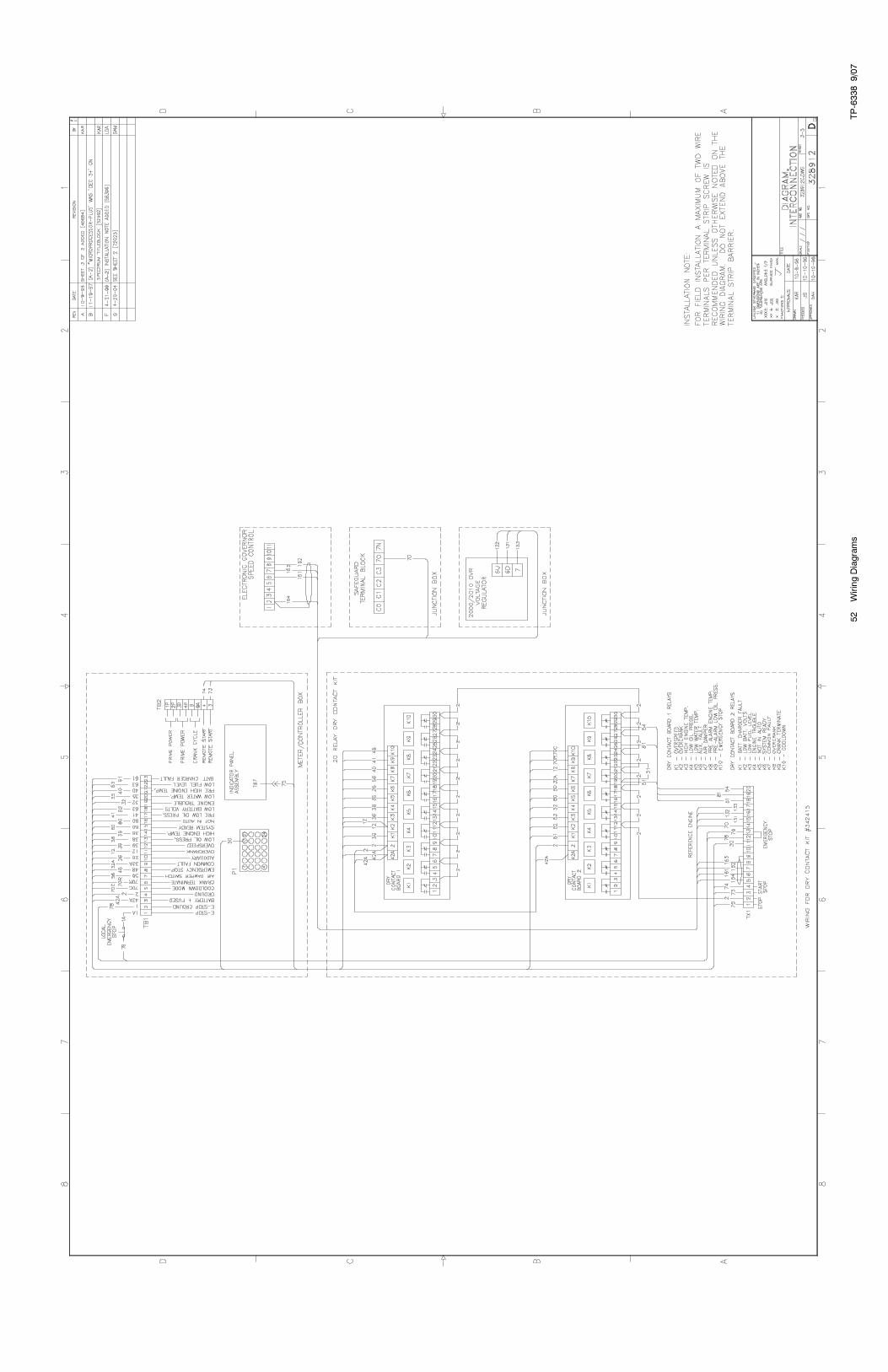
Sheet 3 328912C-G 52
Alternator ReconnectionsPilot-Excited Alternator ADV-5875D-H 11
Housing Electrical ADV-7035B- 27
350/400REOZDC and 450REOZDB Controller Wiring Diagrams Reference
Controller Description Version 4-1 Page Version 4-2 Page
Decision-Maker�550Point-to-Point Wiring Diagram
Sheet 1 GM11503A-H 32 GM11503A-H 32
Sheet 2 GM11503B-H 33 GM11503B-H 33
Schematic Diagram
Sheet 1 ADV-6534A-G 18 ADV-6534A-G 18
Sheet 2 ADV-6534B-G 19 ADV-6534B-G 19
Accessory Connections
Sheet 1 GM16088A-F 34 GM16088A-F 34
Sheet 2 GM16088B-F 35 GM16088B-F 35
Decision-Maker�3+Point-to-Point Wiring Diagram
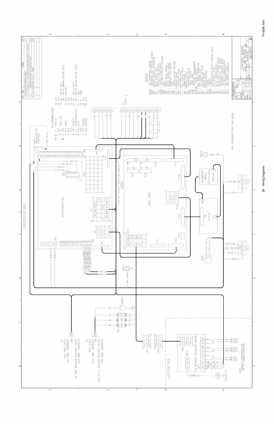
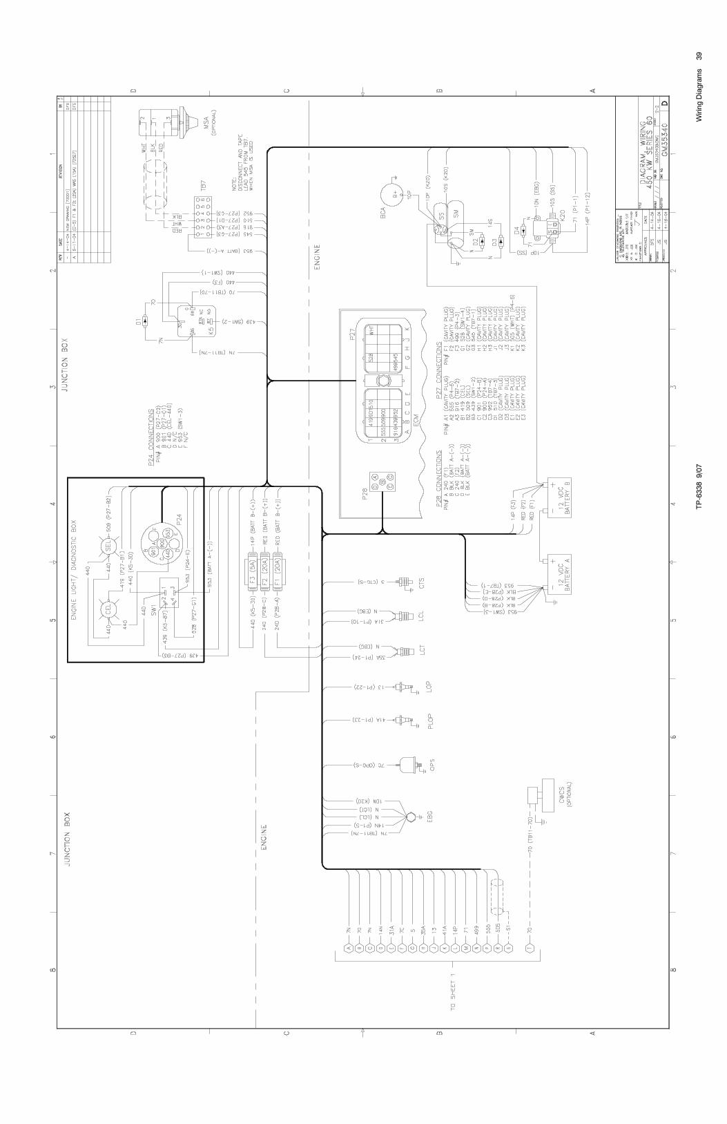
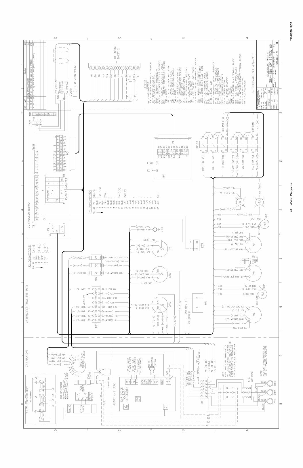
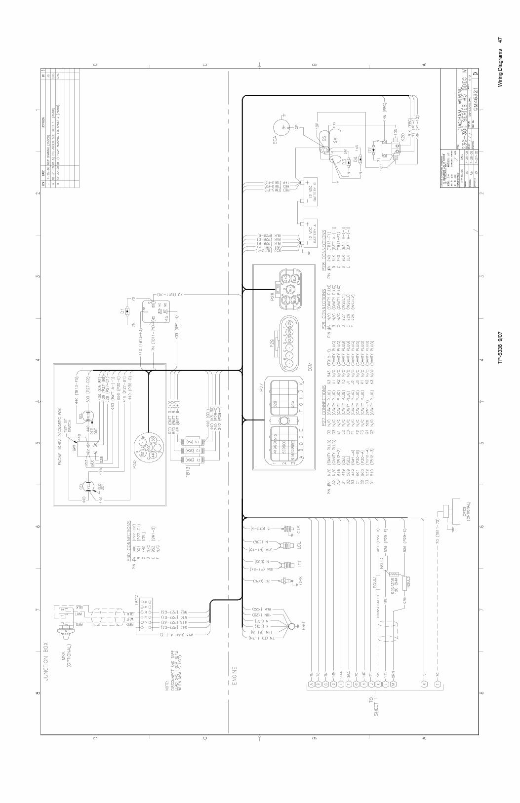
Sheet 1 GM35340A-A 38 GM46318A-B 44
Sheet 2 GM35340B-A 39 GM46318B-B 45
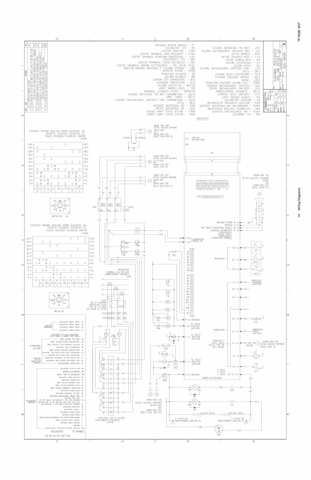
Schematic Diagram ADV-6950-A 22 ADV-7115-B 28
Accessory Connections
Sheet 1 328912A-G 50 328912A-G 50
Sheet 2 328912B-G 51 328912B-G 51
Sheet 3 328912C-G 52 328912C-G 52
Alternator ReconnectionsPilot--Excited Alternator ADV-5875D-H 11 ADV-5875D-H 11
Housing Electrical ADV-7035B- 27 ADV-7035B- 27
Version 4-1 uses digital interface circuit board C-354647.
Version 4-2 uses P22 connector from controller circuit board.
TP-6338 9/078 Controller Identification
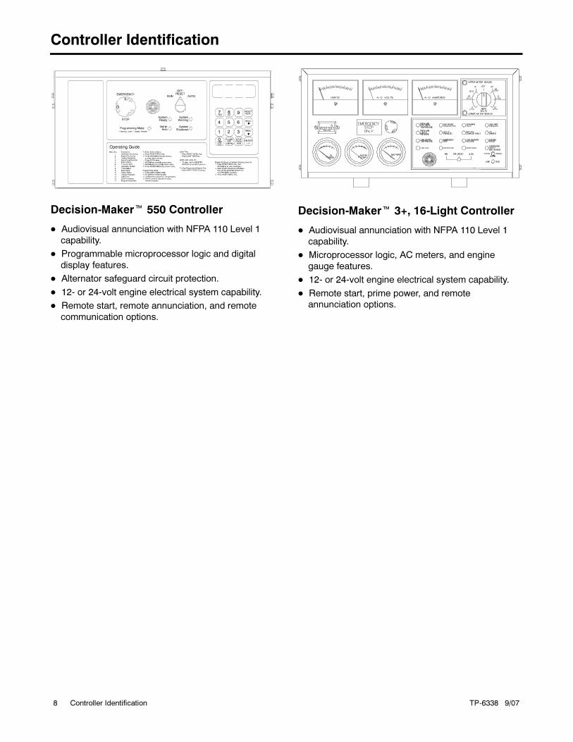
Controller Identification
Decision-Maker� 550 Controller
� Audiovisual annunciation with NFPA 110 Level 1
capability.
� Programmable microprocessor logic and digital
display features.
� Alternator safeguard circuit protection.
� 12- or 24-volt engine electrical system capability.
� Remote start, remote annunciation, and remote
communication options.
Decision-Maker� 3+, 16-Light Controller
� Audiovisual annunciation with NFPA 110 Level 1
capability.
� Microprocessor logic, AC meters, and engine
gauge features.
� 12- or 24-volt engine electrical system capability.
� Remote start, prime power, and remote
annunciation options.
TP-6338
9/07
9WiringDiagrams

TP-6338
9/07
10
WiringDiagrams

TP-6338
9/07
11
WiringDiagrams
TP-6338
9/07
12
WiringDiagrams
TP-6338
9/07
13
WiringDiagrams
TP-6338
9/07
14
WiringDiagrams
TP-6338
9/07
15
WiringDiagrams
TP-6338
9/07
16
WiringDiagrams

TP-6338
9/07
17
WiringDiagrams

TP-6338
9/07
18
WiringDiagrams
TP-6338
9/07
19
WiringDiagrams
TP-6338
9/07
20
WiringDiagrams
TP-6338
9/07
21
WiringDiagrams

TP-6338
9/07
22
WiringDiagrams

TP-6338
9/07
23
WiringDiagrams

TP-6338
9/07
24
WiringDiagrams
TP-6338
9/07
25
WiringDiagrams
TP-6338
9/07
26
WiringDiagrams
TP-6338
9/07
27
WiringDiagrams
TP-6338
9/07
28
WiringDiagrams

TP-6338
9/07
29
WiringDiagrams
TP-6338
9/07
30
WiringDiagrams
TP-6338
9/07
31
WiringDiagrams
TP-6338
9/07
32
WiringDiagrams

TP-6338
9/07
33
WiringDiagrams
TP-6338
9/07
34
WiringDiagrams
TP-6338
9/07
35
WiringDiagrams
TP-6338
9/07
36
WiringDiagrams
TP-6338
9/07
37
WiringDiagrams
TP-6338
9/07
38
WiringDiagrams
TP-6338
9/07
39
WiringDiagrams
TP-6338
9/07
40
WiringDiagrams
TP-6338
9/07
41
WiringDiagrams
TP-6338
9/07
42
WiringDiagrams
TP-6338
9/07
43
WiringDiagrams
TP-6338
9/07
44
WiringDiagrams

TP-6338
9/07
45
WiringDiagrams

TP-6338
9/07
46
WiringDiagrams
TP-6338
9/07
47
WiringDiagrams
TP-6338
9/07
48
WiringDiagrams
TP-6338
9/07
49
WiringDiagrams
TP-6338
9/07
50
WiringDiagrams
TP-6338
9/07
51
WiringDiagrams
TP-6338
9/07
52
WiringDiagrams
TP-6338
9/07
53
WiringDiagrams
TP-6338
9/07
54
WiringDiagrams

TP-6338
9/07
55
WiringDiagrams
TP-6338
9/07
56
WiringDiagrams


� 2002, 2006, 2007 by Kohler Co. All rights reserved.
TP-6338 9/07e
KOHLER CO. Kohler, Wisconsin 53044Phone 920-565-3381, Fax 920-459-1646For the nearest sales/service outlet in theUS and Canada, phone 1-800-544-2444KohlerPower.com
Kohler Power SystemsAsia Pacific Headquarters7 Jurong Pier RoadSingapore 619159Phone (65) 6264-6422, Fax (65) 6264-6455


