40
INDUSTRIAL DEVICES CORPORATION User’s Manual P/N CUS10048 Rev. 1.01 N2 Series Electric Cylinders
INDUSTRIAL DEVICESCORPORATION
User’s ManualP/N CUS10048 Rev. 1.01
N2 SeriesElectric
Cylinders

Blank page inserted as placeholder - Do not print
Table of Content s
i
1. PRODUCT OVERVIEW.................................................................................................................... 1
N2 SERIES FEATURES AND SPECIFICATIONS...................................................................................... 1ELECTRIC CYLINDER CONSTRUCTION (TYPICAL) ................................................................................ 2CYLINDER PART NUMBERS - IDENTIFYING A CYLINDER....................................................................... 3CYLINDER CONFIGURATION GUIDE .................................................................................................... 5
2. MOUNTING YOUR N2 CYLINDER.................................................................................................. 6
MOUNTING REQUIREMENTS............................................................................................................... 6CYLINDER MOUNTING STYLES........................................................................................................... 6MOUNTING ROD ENDS ...................................................................................................................... 6ATTACHING THE LOAD TO THE ROD END ........................................................................................... 7ALIGNING THE ACTUATOR WITH THE LOAD ......................................................................................... 8INSTALLING POSITION SENSORS FOR OVERTRAVEL PROTECTION........................................................ 9POSITION SENSOR DIMENSIONS AND MOUNTING LOCATIONS............................................................ 10SENSOR-TO-CONTROLLER CONNECTIONS........................................................................................ 10
3. APPLICATION CONSIDERATIONS.............................................................................................. 11
MAXIMUM THRUST LOAD................................................................................................................. 11CRITICAL SPEED............................................................................................................................. 11DUTY CYCLE LIMITS ....................................................................................................................... 12ENVIRONMENTAL SPECIFICATIONS................................................................................................... 12TEMPERATURE RATINGS ................................................................................................................. 12PREVENTING EXPOSURE TO CONTAMINANTS ................................................................................... 12
4. OPTIONAL EQUIPMENT - SPECIFICATIONS, DIMENSIONS, AND WIRING............................. 13
BRAKE ON LEADSCREW OPTION (-BS24, -BS115, -BS230) ............................................................ 13BRAKE ON MOTOR OPTION (-BM24, -BM115, -BM230) .................................................................. 14ENCODER OPTION (-EMK/-EM) ...................................................................................................... 15LINEAR POTENTIOMETER OPTION (-L) ............................................................................................. 16
5. FACTORY SERVICE AND ROUTINE FIELD MAINTENANCE..................................................... 17
PERFORMING INSPECTIONS AND ROUTINE MAINTENANCE................................................................. 17ROUTINE MAINTENANCE PROCEDURES............................................................................................ 18PREVENT INJURY TO PERSONNEL.................................................................................................... 18HARDWARE TORQUE....................................................................................................................... 18LUBRICANTS AND ADHESIVES .......................................................................................................... 18INSTALLING A PULLEY, PINION, OR COUPLING .................................................................................. 19LUBRICATING THE LEADSCREW........................................................................................................ 20CHECKING/ADJUSTING DRIVE BELT TENSION................................................................................... 21LUBRICATING GEARS ...................................................................................................................... 22ALIGNING MOTOR PINION................................................................................................................ 23
6. MOUNTING A CUSTOMER SUPPLIED MOTOR.......................................................................... 24
7. TROUBLESHOOTING ............................................................................................................. ...... 25
8. PARTS LIST AND EXPLODED PARTS DIAGRAMS.................................................................... 30
EXPLODED PARTS DIAGRAM - PARALLEL MOTOR MOUNTING............................................................ 31EXPLODED PARTS DIAGRAM - PARALLEL MOTOR MOUNTING............................................................ 32EXPLODED PARTS DIAGRAM - INLINE MOTOR MOUNTING ................................................................. 33EXPLODED PARTS DIAGRAM - INLINE MOTOR MOUNTING ................................................................. 34
9. WARRANTY AND SERVICE COVERAGE.................................................................................... 35

Blank page inserted as placeholder - Do not print
N2 Electric Cylinder - User’s Manual
1
1. Product OverviewIndustrial Devices Corporation’s N2 Series Electric Cylinders are designed for use in a wide variety of industrial, scientific, and commercial applications requiring precise control of linear thrust, speed, or position. This manual will help you install, operate, and maintain your N2 Series Cylinder.
N2 Series FeaturesThe N2 is the next generation of IDC’s N Series, the most prolific electric cylinder design in the world. The N2 provides the performance range of the N Series in a more rugged and higher quality package. Following are just a few of the N2’s more desirable features:
• Highest CustomizationThe N2 is both flexible and robust to accommodate almost every industrial motion control application. In fact, the N2 offers the most available custom options of all IDC products.
• Improved Anti-Rotation SystemA significant N2 improvement lies in the newly designed anti-rotation guide flange, which is six times as strong as the previous N Series version.
• No Extra Charge for Nonstandard Stroke LengthOur manufacturing process can quickly respond to custom stroke length requests, which ensures that you can always specify the length of cylinder that best fits your application.
• Smaller, More Economical Limit SwitchesOur limit switches have also been updated for the N2. The new limit switches are smaller, better sealed (IP67), and less expensive.
• Same Mounting Footprint as N SeriesN2s retain the compact size (very low overall length per usable stroke), and are footprint-compatible with the N Series.
• N2 Compatibility with IDC ControlsIDC controls are designed to optimize the performance of N2 cylinders. See the “Compatible Controls” sec-tion of the table below to ensure that you are using the correct IDC control with your N2 cylinder. If you are not currently using an IDC control, please consult the table below and consider upgrading your application.
N2 SpecificationsThe following are maximum values for the N2 Series. See the IDC Catalog for full specifications.
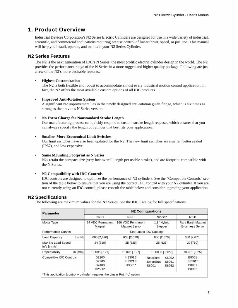
Parameter N2 Configurations
N2-D N2-H N2-S/P N2-B
Motor Type 24 VDC PermanentMagnet
160 VDC PermanentMagnet Servo
1.8° HybridStepper
Rare Earth MagnetBrushless Servo
Performance Curves See Latest IDC Catalog
Load Capacity lbs [N] 600 [2,670] 600 [2,670] 600 [2,670] 600 [2,670]
Max No Load Speed in/s [mm/s]
24 [610] 25 [635] 25 [635] 30 [760]
Repeatability in [mm] ±0.005 [.127] ±0.005 [.127] ±0.0005 [.0127] ±0.001 [.025]
Compatible IDC Controls D2200D2300D2400D2500*
H3301BH3321BH3501*
B8001B8501*B8961B8962
*This application (control + cylinder) requires the Linear Pot. (-L) option.
NextStepSmartStepS6001
S6002S6961S6962
N2 Electric Cylinder - User’s Manual
2
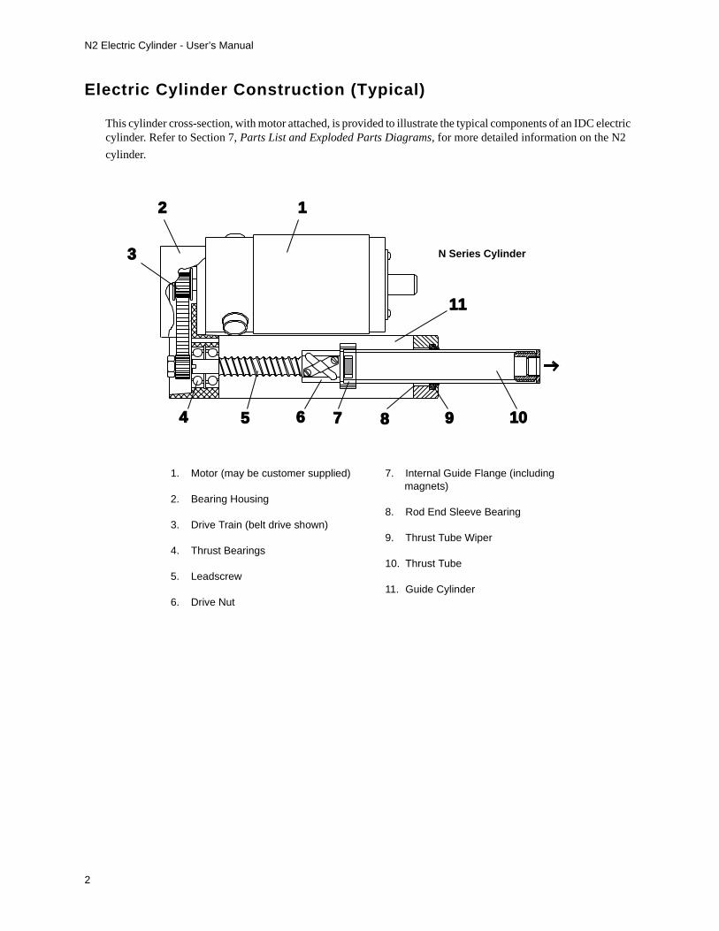
Electric Cylinder Construction (Typical)
This cylinder cross-section, with motor attached, is provided to illustrate the typical components of an IDC electric cylinder. Refer to Section 7, Parts List and Exploded Parts Diagrams, for more detailed information on the N2
cylinder.
10
12
3
4 5 6 7 9
11
8
N Series Cylinder
1. Motor (may be customer supplied)
2. Bearing Housing
3. Drive Train (belt drive shown)
4. Thrust Bearings
5. Leadscrew
6. Drive Nut
7. Internal Guide Flange (including magnets)
8. Rod End Sleeve Bearing
9. Thrust Tube Wiper
10. Thrust Tube
11. Guide Cylinder
N2 Electric Cylinder - User’s Manual
3
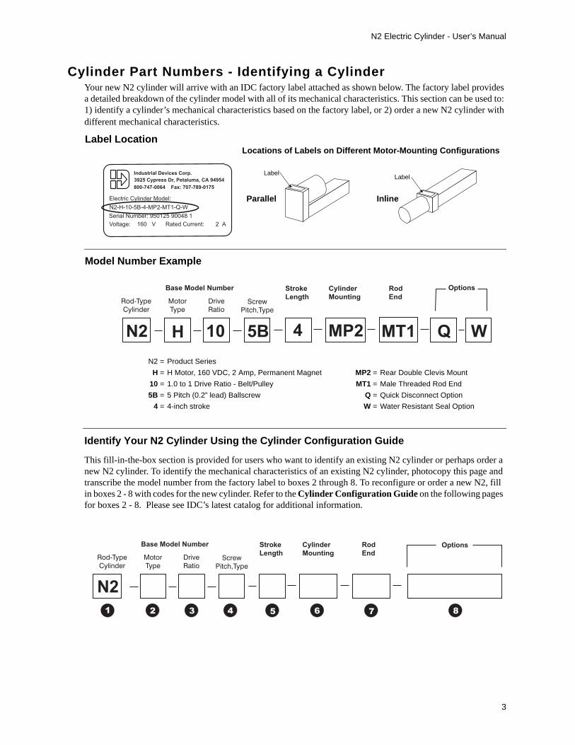
Cylinder Part Numbers - Identifying a CylinderYour new N2 cylinder will arrive with an IDC factory label attached as shown below. The factory label provides a detailed breakdown of the cylinder model with all of its mechanical characteristics. This section can be used to: 1) identify a cylinder’s mechanical characteristics based on the factory label, or 2) order a new N2 cylinder with different mechanical characteristics.
N2
Rod-Type
Cylinder
Motor
Type
Drive
RatioScrew
Pitch,Type
Base Model Number Stroke
Length
Cylinder
Mounting
Rod
End
Options
H 10 5B 4 MP2 MT1 Q W
N2 = Product Series
H = H Motor, 160 VDC, 2 Amp, Permanent Magnet MP2 = Rear Double Clevis Mount
10 = 1.0 to 1 Drive Ratio - Belt/Pulley MT1 = Male Threaded Rod End
5B = 5 Pitch (0.2” lead) Ballscrew Q = Quick Disconnect Option
4 = 4-inch stroke W = Water Resistant Seal Option
Identify Your N2 Cylinder Using the Cylinder Configuration Guide
This fill-in-the-box section is provided for users who want to identify an existing N2 cylinder or perhaps order a new N2 cylinder. To identify the mechanical characteristics of an existing N2 cylinder, photocopy this page and transcribe the model number from the factory label to boxes 2 through 8. To reconfigure or order a new N2, fill in boxes 2 - 8 with codes for the new cylinder. Refer to the Cylinder Configuration Guide on the following pages for boxes 2 - 8. Please see IDC’s latest catalog for additional information.
LabelLabel
Locations of Labels on Different Motor-Mounting Configurations
InlineParallel
Serial Number: 950125 90048 1
Industrial Devices Corp.
N2-H-10-5B-4-MP2-MT1-Q-W
3925 Cypress Dr, Petaluma, CA 94954
800-747-0064 Fax: 707-789-0175
Electric Cylinder Model:
Voltage: 160 V Rated Current: 2 A
N2
Rod-Type
Cylinder
Motor
Type
Drive
RatioScrew
Pitch,Type
Base Model Number Stroke
Length
Cylinder
Mounting
Rod
EndOptions
1 2 3 4 5 6 7 8
Label Location
Model Number Example

N2 Electric Cylinder - User’s Manual
4
Cylinder Configuration Guide
�D 24VDC, 4.5 Amp, Permanent Magnet Motor
H 160VDC, 2 Amp, Permanent Magnet Motor
P22[*x] NEMA 23 Frame, Step Motor, 3 Stack
S32[*x] NEMA 34 Frame, Step Motor, 2 Stack
B23 23 Frame Brushless Servo Motor
X Customer Supplied Motor ( motor described in “Options” element of part number)
Motor Type
� Drive Ratio10 1.0:1 Drive Belt/Pulley (1.0:1 exact ratio)
15 1.5:1 Drive Belt/Pulley (1.5:1 exact ratio)
20 2.0:1 Drive Belt/Pulley (2.0:1 exact ratio)
25 2.5:1 Helical Gear (2.5:1 exact ratio)
31 3.1:1 Helical Gear (3.125 exact, or 50:16 ratio)
120 12.0:1 Helical Gear (12:1 exact ratio)
10L 1.0:1 Inline Coupling [Note: Direct 1:1 coupling is the only ratio available for Inline Models
� Screw Type 5A 5 Pitch (.2” lead) acme leadscrew
8A 8 Pitch (.125” lead) acme leadscrew
2B 2 Pitch (.5” lead) ballscrew
5B 5 Pitch (.2” lead) ballscrew
� Stroke Length - Specified in inches
� MountingStyles
MF1*MF2*MF3*
Front Rectangular Flange Rear Rectangular FlangeFront & Rear Rectangular Flange
MP2MP3
Rear Double Clevis Mount (shown)Rear Double Clevis Mountwith Pivot Base
MS1 Side End Angles
MS2 Side Lugs
MS6* Side Tapped Mounting Holes
MT4 Trunnion Mount(Inline versions only)
*Add M suffix for Metric version (e.g. MF1M, MS6M, etc.)
*Insert one of the following for x:
N = 8 leads (windings can be wired in Series or Parallel)
T = Windings pre-wired in SeriesV = Windings pre-wired in Parallel

N2 Electric Cylinder - User’s Manual
5
Cylinder Configuration Guide
BM Brake on Motor
BS Brake on Leadscrew
DB Double Bearing
EM Encoder on Motor (500 line)
EMK Encoder on Motor (1000 line)
F Subfreezing
H High Temperature
L Linear Potentiometer
PB Protective Boot
PN Pre-loaded Nut
Q Quick Disconnect
W Water Resistant Seal
Motor Mod Codes for X Motors (Customer Supplied) also found in Option part of Part Number
FC2 Clevis (includes MT1)
FE2 Female Eye (includes FT1)
FS2 Spherical Joint (includes FT1)
FT1* Female Thread
MT1* Male Thread
*Add M suffix for metric version (e.g. FT1M, MT1M, etc.)
Note: Rod-End dimensions can be found in the latest IDC Catalog
� Rod Ends
� CylinderOptions

N2 Electric Cylinder - User’s Manual
6
2. Mounting Your N2 Cylinder
Mounting Requirements1. The structure on which the cylinder is mounted must be capable of holding three times (3X) the cylinder
load and be rigid enough to prevent undue deflection or distortion of the cylinder or its supporting members.2. The cylinder must be mounted parallel to the travel of the load to ensure proper alignment (this is especially
important with externally guided loads using rails, bearings, etc.).3. All mounting surfaces must be flat and clean to provide secure and stable fittings.4. Units with flat surface mounts (MF1, MF2, MF3, MS1, MS6) must be rigidly mounted.
Cylinder Mounting StylesEach cylinder mounting style presents different application considerations. Find your mounting style(s) in the table below and pay special attention to the corresponding “Application Requirements” column.
Mounting Rod EndsAs with mounting styles, different rod ends also require certain application considerations. Find your rod end(s)
in the table below and pay special attention to the corresponding “Application Requirements” column.
Warning! Ensure that power to the electric cylinder is OFF before attempting any installa-tion, adjustment, or modification to the cylinder mounting, rod end attachment, or the load.
Cylinder Mounting Style Application Requirements
MF1 - Front Flange Not recommended for use in horizontal applications with stroke lengths greater than 12 inches unless there is additional support in the rear of the cylinder.
MF2 - Rear Flange Not recommended for use in horizontal applications with stroke lengths greater than 12 inches unless there is additional support in the front of the cylinder.
MF3 - Front & Rear Flange Do not allow the body of the cylinder to twist while aligning the front and rear mounting flanges to their mating surfaces.
MP2 - Rear Clevis Use a flexible rod end or load attachment to compensate for system misalignment.Example: FC2, FE2, or FS2 rod ends
MS1 - Side End Angle Brackets Bolts used to secure brackets must be able to withstand a shearing force of up to 1000 lbs.
MS2 - Side Lugs Bolts used to secure brackets must be able to withstand a shearing force of up to 1000 lbs.
MS6 - Side Tapped Holes Mounting-screws (used with Side Tapped Holes) must resist a peak shear force of up to 1000 lbs. This mounting alone is not recommended for loads in excess of 500 lbs.
MT4 - Trunnion Mount Use a flexible rod end or load attachment to compensate for system misalignment.
Rod End Style Application Requirements
FC2 - Clevis w/MT1 Thread Clevis must be secured by its locknut when in desired position. The mounting pin must be secured with a cotter pin after it is inserted into the double clevis holes.
FE2 - Female Eye Adjust for maximum thread engagement.
FS2 - Spherical Joint Not recommended if stiff or rigid load attachment is required.
FT1 - Female Thread Maximum thread depth is 3/8 inch. Exceeding maximum thread depth may cause contact with leadscrew or cause damage when the thrust tube is fully retracted.
MT1 - Male Thread Any attachment to an MT1 rod end must be secured in place by a locknut

N2 Electric Cylinder - User’s Manual
7
Attaching the Load to the Rod End
Warning!Do Not Exceed the Maximum Torque Limits on the Thrust Tube when attaching the load to the rod end. Failure to heed this warning could cause irreparable damage to the internal guide flange. Maximum torque limits are shown on the drawing below.
Hexagonal flats are provided at the end of the thrust tube to prevent rotation while the rod end attachment is being secured.
Use wrench on flats to prevent rotation of thrust tube during load attachment
Do Not Exceed 50 ft lbs torque in the Clockwise (CW) direction
Do Not Exceed 50 in lbs torque in the Counter Clockwise (CCW) direction
N2 Electric Cylinder - User’s Manual
8
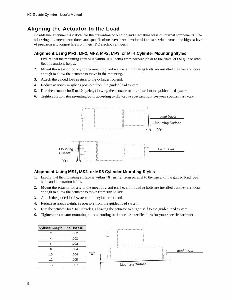
Aligning the Actuator to the LoadLoad-travel alignment is critical for the prevention of binding and premature wear of internal components. The following alignment procedures and specifications have been developed for users who demand the highest level of precision and longest life from their IDC electric cylinders.
Alignment Using MF1, MF2, MF3, MP2, MP3, or MT4 Cylinder Mounting Styles1. Ensure that the mounting surface is within .001 inches from perpendicular to the travel of the guided load.
See illustrations below.
2. Mount the actuator loosely to the mounting surface, i.e. all mounting bolts are installed but they are loose enough to allow the actuator to move in the mounting.
3. Attach the guided load system to the cylinder rod end.
4. Reduce as much weight as possible from the guided load system.
5. Run the actuator for 5 to 10 cycles, allowing the actuator to align itself to the guided load system.
6. Tighten the actuator mounting bolts according to the torque specifications for your specific hardware.
Alignment Using MS1, MS2, or MS6 Cylinder Mounting Styles1. Ensure that the mounting surface is within “X” inches from parallel to the travel of the guided load. See
table and illustration below.
2. Mount the actuator loosely to the mounting surface, i.e. all mounting bolts are installed but they are loose enough to allow the actuator to move from side to side.
3. Attach the guided load system to the cylinder rod end.
4. Reduce as much weight as possible from the guided load system.
5. Run the actuator for 5 to 10 cycles, allowing the actuator to align itself to the guided load system.
6. Tighten the actuator mounting bolts according to the torque specifications for your specific hardware.
.001
Mounting Surface
load travel
.001
MountingSurface
load travel
Cylinder Length “X” inches
2 .002
4 .002
6 .003
8 .004
10 .004
12 .005
18 .007
"X"
Mounting Surface
load travel

N2 Electric Cylinder - User’s Manual
9
Installing Position Sensors for Overtravel ProtectionAlthough an “elastomeric spring” inside the actuator is designed to prevent actuator jams, position sensors (aka limit switches) are required to prevent such potentially damaging jam conditions. If the motor is accidentally commanded to move toward a hard-stop, position sensors can signal a stop before a collision occurs. To work properly, position sensors must be positioned inward from the hard-stop, and wired correctly to the motor controller.Note: Using the physical limits of the cylinder (hard stops) will reduce cylinder life and can cause premature component failure.
Mounting Location - Deceleration DistanceThe position sensor’s location along the cylinder is associated with the beginning of a deceleration, not the final stopping point. Therefore, position sensors must be mounted inward of the cylinder hard-stops to provide a slowdown area to prevent jamming. The faster the approach speed, the longer it takes to stop the cylinder, so deceleration distance varies with actuator speed, load, and cylinder/control type. A small amount of adjustment may be necessary during initial setup.
Important Installation Notes1. Position sensors may be mounted along either side of an N2 cylinder. Note: Position sensors can be mounted
on only one side of a cylinder equipped with the Linear Potentiometer (-L) option.
2. Distance between sensors should be 1.50 inches or more. If sensors are located closer than 1.50 inches apart, they may trigger at the same time.
3. Using position sensors for end-of-travel protection reduces effective travel distance. Consult the factory.
4. IDC’s D2200, D2300 and D2400 series controls use only PSR-1 and PSN-1 position sensors.
Position Sensor Specifications for Sensors Used on N2 Electric Cylinders Sensor Series PSR-1 PSR-2 PSN-1 PSN-2 *PSP-1 *PSP-2
Sensor Type Mechanical Reed Hall-Effect
Output Type Contact Closure Sinking, Open Collector (NPN) Sourcing (PNP)
Connection Norm. Open Norm. Closed Norm. Open Norm. Closed Norm. Open Norm. Closed
LED Color Green Red Green Red Yellow Red
Leads (wiring) 2 + shield, 26 AWG, 3 meters 3 + shield, 26 AWG, 3 meters
Sup
ply Voltage 4 - 120V (AC or DC) 10 - 24 VDC
Current 5 mA @ 12 VDC; 10 mA @ 24 VDC
Power 0.24 W
Leakage Current (max.) 0.01 mA
Out
put
DC Maximum 120 VDC 24 VDC
AC Maximum 120 VAC
Current Max. 50 mA 100mA
Power Max. 6 W 3 W
Operating Temp. -4° to 158°F [-20° to 70°C]
Storage Temp. -4° to 176°F [-20° to 80°C]
Environmental Rating IEC Standard IP67
*Not compatible with IDC motion controllers
C A U T I O NWhen installing a position sensor, tighten the clamp screw to a maximum 7.0 oz-in of torque. Failureto heed this caution could cause irreparable damage to the sensor. Tighten the clamp screw gently andonly to the point where the sensor assembly feels secure and does not slide along the cylinder wall.
N2 Electric Cylinder - User’s Manual
10
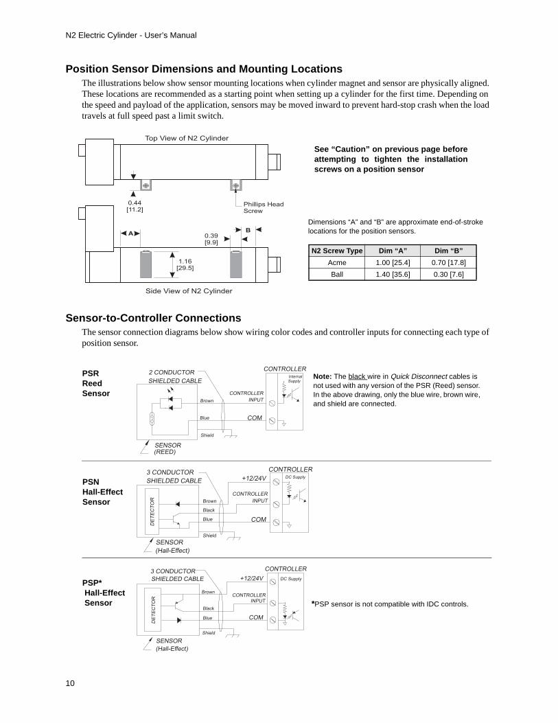
Position Sensor Dimensions and Mounting LocationsThe illustrations below show sensor mounting locations when cylinder magnet and sensor are physically aligned. These locations are recommended as a starting point when setting up a cylinder for the first time. Depending on the speed and payload of the application, sensors may be moved inward to prevent hard-stop crash when the load travels at full speed past a limit switch.
Sensor-to-Controller ConnectionsThe sensor connection diagrams below show wiring color codes and controller inputs for connecting each type of position sensor.
0.44[11.2]
AB
1.16[29.5]
0.39[9.9]
Phillips HeadScrew
Top View of N2 Cylinder
Side View of N2 Cylinder
N2 Screw Type Dim “A” Dim “B”
Acme 1.00 [25.4] 0.70 [17.8]
Ball 1.40 [35.6] 0.30 [7.6]
Dimensions “A” and “B” are approximate end-of-stroke locations for the position sensors.
See “Caution” on previous page beforeattempting to tighten the installationscrews on a position sensor
CONTROLLER
Shield
Brown
Blue COM
INPUT
CONTROLLERInternalSupply
SENSOR(REED)
SHIELDED CABLE
2 CONDUCTOR
Black
Blue
Shield
COM
CONTROLLER
Brown
CONTROLLER
INPUT
+12/24V DC Supply
SENSOR
(Hall-Effect)
SHIELDED CABLE
3 CONDUCTOR
DE
TE
CT
OR
Black
Blue
Shield
COM
CONTROLLERBrown
CONTROLLER
INPUT
+12/24V DC Supply
DE
TE
CT
OR
SENSOR
(Hall-Effect)
SHIELDED CABLE
3 CONDUCTOR
Note: The black wire in Quick Disconnect cables is not used with any version of the PSR (Reed) sensor. In the above drawing, only the blue wire, brown wire, and shield are connected.
PSRReed Sensor
*PSP sensor is not compatible with IDC controls.
PSNHall-EffectSensor
PSP* Hall-Effect Sensor

N2 Electric Cylinder - User’s Manual
11
3. Application ConsiderationsCertain conditions can limit cylinder performance and should be addressed prior to installation and operation. Adherence to the following application guidelines will ensure a successful application.
Maximum Thrust LoadExceeding the maximum thrust load will cause the leadscrew to buckle and become permanently damaged.
Critical SpeedAll leadscrew systems have a rotational speed limit at which harmonic vibrations begin to occur. Sustained operation beyond this critical speed may cause the leadscrew to vibrate or whip violently, eventually bending or warping the screw. The critical speed limit is typically caused by unsupported leadscrew length.
Maximum Thrust Load for all configurations of N2 cylinders is 600 lbs [2670 N]
Thrust Load
Speed Limitations Due to Stroke Length
ScrewType
Max. Speed per Cylinder StrokeSpeed = in/sec [mm/sec]
< 12'' < 18''
2B 36.7 [932]
5B 15 [381]
5A 15 [381] 13.8 [351]
8A 9.4 [239]
Application Note:IDC programmable controls have a maximum veloc-ity parameter that can be configured not to exceed the “critical speed.”
L
N2 Electric Cylinder - User’s Manual
12
Duty Cycle LimitsDuty cycle is the percentage of ON Time divided by Total Cycle Time for the worst-case 10-minute period. During operation, duty cycle represents the maximum acceptable power dissipation of the motor and the frictional heat losses of the internal cylinder components, primarily the leadscrew/drivenut assembly. In general, ballscrew actuators are rated for 100% duty cycle and acme screws are rated for a maximum of 60%. Your motor may also have duty cycle limitations. Consult your IDC Catalog for more information on duty cycles. Exceeding the recommended duty cycle will damage the motor or internal cylinder components.
Environmental SpecificationsThe following environmental specifications must be observed for optimal cylinder performance.
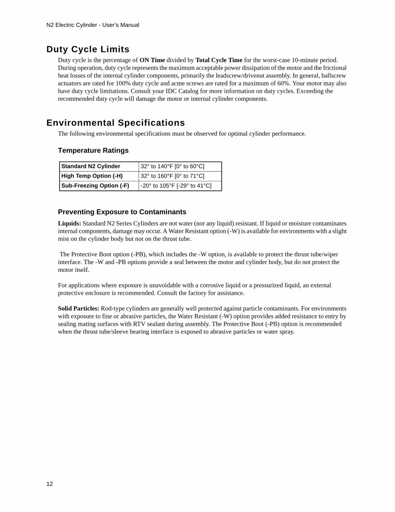
Temperature Ratings
Preventing Exposure to Contaminants
Liquids: Standard N2 Series Cylinders are not water (nor any liquid) resistant. If liquid or moisture contaminates internal components, damage may occur. A Water Resistant option (-W) is available for environments with a slight mist on the cylinder body but not on the thrust tube.
The Protective Boot option (-PB), which includes the -W option, is available to protect the thrust tube/wiper interface. The -W and -PB options provide a seal between the motor and cylinder body, but do not protect the motor itself.
For applications where exposure is unavoidable with a corrosive liquid or a pressurized liquid, an external protective enclosure is recommended. Consult the factory for assistance.
Solid Particles: Rod-type cylinders are generally well protected against particle contaminants. For environments with exposure to fine or abrasive particles, the Water Resistant (-W) option provides added resistance to entry by sealing mating surfaces with RTV sealant during assembly. The Protective Boot (-PB) option is recommended when the thrust tube/sleeve bearing interface is exposed to abrasive particles or water spray.
Standard N2 Cylinder 32° to 140°F [0° to 60°C]
High Temp Option (-H) 32° to 160°F [0° to 71°C]
Sub-Freezing Option (-F) -20° to 105°F [-29° to 41°C]

N2 Electric Cylinder - User’s Manual
13
4. Optional Equipment - Specifications, Dimensions, and Wiring
Brake on Leadscrew Option (-BS24, -BS115, -BS230) This brake option provides a spring-set, electrically-released friction brake mounted to an extension of the leadscrew. It prevents backdriving when the unit is at rest, or in case of power failure. Without power, the brake is engaged. Applying power releases the brake, allowing motion to occur.
Application Note: This option is used only for in-position holding, it should not be used for stopping a moving load.
SpecificationParameters
Leadscrew-Mounted Brake Configurations
-BS24 -BS115 -BS230
Voltage 24 VDC 115 VAC 230 VAC
Current (Amps) 0.667 0.14 0.07
Power (Watts) 16
Holding Torque (in lbs) 30
Cable Length (ft) 12
Holding Force
Screw Type and Pitch2B (2 Pitch Ballscrew)5B (5 Pitch Ballscrew)
5A (5 Pitch Acme Screw)8A (8 Pitch Acme Screw)
Holding Force240 [1100]600 [2670]600 [2670]600 [2670]
Specifications
Dimensions
Electrical
Cable: Dia 0.17 [4.3], 0.25R [6.4R]MINIMUM BEND RADIUS
Dia 3.08[78.2] 2.04
[51.8]
0.55[14.0]
2.73[69.3]
1.00[25.4]
Brake
Coil
+
–
Rectifier
115 VAC (-BS115)230 VAC (-BS230)
Brake
Coil
24 VDC (-BM24)
Connections
N2 Electric Cylinder - User’s Manual
14
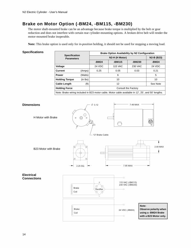
Brake on Motor Option (-BM24, -BM115, -BM230) The motor shaft-mounted brake can be an advantage because brake torque is multiplied by the belt or gear reduction and does not interfere with certain rear cylinder-mounting options. A broken drive belt will render the motor-mounted brake inoperable.
Note: This brake option is used only for in-position holding, it should not be used for stopping a moving load.
SpecificaitonParameters
Brake Option Availability by N2 Configuration
N2-H (H Motor) N2-B (B23)
-BM24 -BM115 -BM230 -BM24
Voltage 24 VDC 115 VAC 230 VAC 24 VDC
Current (Amps) 0.25 0.05 0.03 0.21
Power (Watts) 6 5
Holding Torque (in lbs) 10 10
Cable Length (ft) 12 See Note
Holding Force Consult the Factory
Note: Brake wiring included in B23 motor cable. Motor cable available in 12’, 25’, and 50’ lengths.
Specifications
Dimensions
Electrical
2.25 SQ. 7.95 MAX
2.00 MAX
H Motor with Brake
B23 Motor with Brake
3.12
12' Brake Cable
7.48 MAX
Brake
Coil
+
–
Rectifier
115 VAC (-BM115)230 VAC (-BM230)
Brake
Coil
24 VDC (-BM24)
Note:Observe polarity when using a -BM24 Brake with a B23 Motor only.
Connections
N2 Electric Cylinder - User’s Manual
15
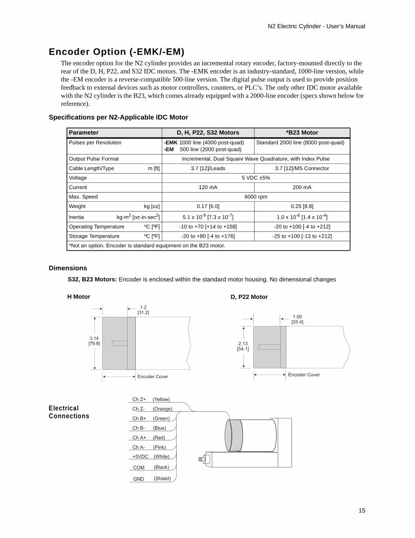
Encoder Option (-EMK/-EM)The encoder option for the N2 cylinder provides an incremental rotary encoder, factory-mounted directly to the rear of the D, H, P22, and S32 IDC motors. The -EMK encoder is an industry-standard, 1000-line version, while the -EM encoder is a reverse-compatible 500-line version. The digital pulse output is used to provide position feedback to external devices such as motor controllers, counters, or PLC’s. The only other IDC motor available with the N2 cylinder is the B23, which comes already equipped with a 2000-line encoder (specs shown below for reference).
Parameter D, H, P22, S32 Motors *B23 Motor
Pulses per Revolution -EMK 1000 line (4000 post-quad)-EM 500 line (2000 post-quad)
Standard 2000 line (8000 post-quad)
Output Pulse Format Incremental, Dual Square Wave Quadrature, with Index Pulse
Cable Length/Type m [ft] 3.7 [12]/Leads 3.7 [12]/MS Connector
Voltage 5 VDC ±5%
Current 120 mA 200 mA
Max. Speed 6000 rpm
Weight kg [oz] 0.17 [6.0] 0.25 [8.8]
Inertia kg-m2 [oz-in-sec2] 5.1 x 10⁻⁹ [7.3 x 10⁻⁷] 1.0 x 10⁻⁶ [1.4 x 10⁻⁴]
Operating Temperature ºC [ºF] -10 to +70 [+14 to +158] -20 to +100 [-4 to +212]
Storage Temperature ºC [ºF] -20 to +80 [-4 to +176] -25 to +100 [-13 to +212]
*Not an option. Encoder is standard equipment on the B23 motor.
Ch Z+ (Yellow)
Ch Z- (Orange)
Ch B+ (Green)
Ch B- (Blue)
Ch A+ (Red)
Ch A- (Pink)
+5VDC (White)
GND (Shield)
(Black)COM
Specifications per N2-Applicable IDC Motor
ElectricalConnections
H Motor D, P22 Motor
Encoder Cover
1.00[25.4]
2.13[54.1]
1.2[31.2]
Encoder Cover
3.14[79.8]
Dimensions
S32, B23 Motors: Encoder is enclosed within the standard motor housing. No dimensional changes

N2 Electric Cylinder - User’s Manual
16
Linear Potentiometer Option (-L)The Linear Potentiometer resides within the cylinder housing and is energized by an external DC power supply. The potentiometer wiper moves in conjunction with the cylinder thrust tube providing an analog voltage feedback signal which is proportional to the linear displacement.
Example: Using a 5 volt supply, 0VDC = 0% Stroke; 2.5VDC = 50% Stroke; and 5 VDC = 100% Stroke
Application Notes1. This option is not recommended for high vibration environments.2. This option is required when the N2 is used with IDC D2500, H3500, H4500, and B8500 series controls.3. For improved accuracy, users may want to “map” or calibrate each unit.
Stroke (inches) Resistance (ohms) Max. Non-Linearity
2 3000 ± 20% ±1%
4 6000 ± 20% ±1%
6 9000 ± 20% ±1%
8 9000 ± 30% ±1%
10 9000 ± 30% ±1%
12 7000 ± 30% ±1% (5% to 95% of function)
18-DB (16.5 actual) 7000 ± 30% ±1% (5% to 95% of function)
N2Cylinder Type
DIM “A” with2, 4, 6, 8, 10’’ Stroke
in [mm]
DIM “A” with12, 18’’ Stroke
in [mm]
ACME 1.69 [42.9] 1.69 [42.9]
BALL 1.25 [31.7] 1.38 [35.1]
Dimensions (side-mounted Linear Pot)
ElectricalConnections
Specifications
A
1.1
5[2
9.2
]
0.5
7[1
4.6
]
0.40 [10.2]
0.50 [12.7]
0.25 [6.4]
CABLE:0.15 [3.9], R 0.51 [13.0]MINIMUM BEND RADIUS
2.00 [50.8]
Brown
Black
Blue
Shield
+VDC
Wiper Feedback
GND
N2 Electric Cylinder - User’s Manual
17
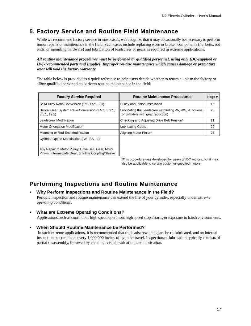
5. Factory Service and Routine Field MaintenanceWhile we recommend factory service in most cases, we recognize that it may occasionally be necessary to perform minor repairs or maintenance in the field. Such cases include replacing worn or broken components (i.e. belts, rod ends, or mounting hardware) and lubrication of leadscrew or gears as required in extreme applications.
All routine maintenance procedures must be performed by qualified personnel, using only IDC-supplied or IDC-recommended parts and supplies. Improper routine maintenance which causes damage or premature wear will void the factory warranty.
The table below is provided as a quick reference to help users decide whether to return a unit to the factory or allow qualified personnel to perform routine maintenance in the field.
Performing Inspections and Routine Maintenance• Why Perform Inspections and Routine Maintenance in the Field?
Periodic inspection and routine maintenance can extend the life of your cylinder, especially under extreme operating conditions.
• What are Extreme Operating Conditions?Applications such as continuous high speed operation, high speed stops/starts, or exposure to harsh environments.
• When Should Routine Maintenance be Performed? In such extreme applications, it is recommended that the leadscrew and gears be re-lubricated, and an internal inspection be completed every 1,000,000 inches of cylinder travel. Inspection/re-lubrication typically consists of partial disassembly, followed by cleaning, visual evaluation, and lubrication.
Factory Service Required Routine Maintenance Procedures Page #
Belt/Pulley Ratio Conversion (1:1, 1.5:1, 2:1) Pulley and Pinion Installation 19
Helical Gear System Ratio Conversion (2.5:1, 3.1:1, 3.5:1, 12:1)
Lubricating the Leadscrew (excluding -W, -BS, -L options, or cylinders with gear reduction)
20
Leadscrew Modification Checking and Adjusting Drive Belt Tension* 21
Motor Orientation Modification Lubricating Gears 22
Mounting or Rod End Modification Aligning Motor Pinion* 23
Cylinder Option Modification (-W, -BS, -L)
Any Repair to Motor Pulley, Drive Belt, Gear, Motor Pinion, Intermediate Gear, or Inline Coupling/Sleeve
*This procedure was developed for users of IDC motors, but it may also be applicable to certain customer-supplied motors.

N2 Electric Cylinder - User’s Manual
18
Routine Maintenance ProceduresRoutine maintenance procedures are provided in the remainder of this section. Order parts and supplies from your local IDC Distributor.
Prevent Injury to PersonnelDo not attempt to perform any routine maintenance procedure while power is connected to the motor/cylinder.
Hardware TorqueBefore attempting any routine maintenance procedure, become familiar with the Torque Specification Table below. Always refer to this table before applying torque to any of the listed parts.
Lubricants and AdhesivesWhen a specific lubricant or adhesive is required, it will be specified within the applicable procedure.
Torque Specification Table
Description of Part Reference #(see Exploded Parts
Diagrams)
HardwareSize
Maximum Torque(in-lbs)
Bolt, Guide Cylinder 16, 22, 32, 44 1/4 - 20 UNC 50
Screw, Set, Coupler 45 1/4 - 20 UNC 40
Bolt, Motor Mounting 24 10 - 32 UNF8 - 32 UNC
3220
Screw, Set, Pulley/Pinion 29 8 - 32 UNC 20
Screw, Cover Plate 28, 35 8 - 32 UNC 20

N2 Electric Cylinder - User’s Manual
19
Installing a Pulley, Pinion, or Coupling
.480"
“A”
“B”
.075"
Gear RatioDimension “A”Pinion Spacing
Dimension “B”Pinion Spacing
2.5:1 1.018''
3.1:1 1.018''
3.1:1 (H Motor only) .155''
12:1 .233''
Refer to the appropriate illustration and/or table for your pulley, pinion, or coupling.
1. Clean the motor shaft and bore free of anygrease.
2. Apply Loctite #680 (green) to the motorshaft and the bore of the pulley, pinion, orcoupling.
3. Slide pulley, pinion, or coupling onto themotor shaft with a rotating motion toevenly distribute the Loctite.
4. Position pulley, pinion, or couplingaccording to the appropriate “spacing”table or drawing (see App. Note #2).
5. Ensure that one setscrew is positioned on aflat, in a dimple, over a key or keyway.
6. Apply Loctite #262 (red) to the setscrew(s).
7. Tighten setscrew(s).
8. Refer to the motor-mounting procedure onthe previous page.
Pulley Spacing
Pinion Spacing
Coupling Spacing(inline motors)
(see table below drawing)
Pulley spacing (.480'') must be measured from the inner face of the pulley to the face of the mounting plate (see App. Note #2)
“A” must be measured from the outer edge of the pinion to the face of the mounting plate (see App. Note #2)
“B” must be measured from the inner edge of the pinion to the face of the mounting plate (see App. Note #2)
Coupling spacing (.075'') must be measured from the inner face of the coupling to the face of the mounting plate (see Application Note)
Application Notes
1. WARNING! The combination of pulleyplacement and operating torque may exceedmotor shaft load capacity. It is the user’sresponsibility to verify adequate shaft loadcapacity.
2. If a supplemental mounting plate or adapteris used, it must be installed beforemeasuring pulley, pinion, or couplingspacing.
3. All spacing dimensions for pulleys, pinions,or couplings have a tolerance of ±.005inches.

N2 Electric Cylinder - User’s Manual
20
Lubricating the LeadscrewNote: Do not attempt to lubricate the leadscrew of a cylinder with the -L (Linear Potentiometer) Option. This procedure must be done at the factory.
Recommended Lubricants
1. Remove upper cover plate from the gear housing by removing two (2) mounting-screws (8/32 Phillips).
2. Remove lower cover plate by removing two (2) mounting-screws (8/32 Phillips) and two (2) socket head cap screws (1/4-20). The two SHCS are also used to secure the lower part of the guide housing.
3. Remove two (2) SHCS (inside gear housing) that secure the upper part of the guide housing.
4. Remove guide housing by sliding it away from the thrust tube.
5. Move the drive nut (attached to thrust tube) to the far end of the leadscrew.
6. Remove as much of the old grease from the cylinder as possible.
7. With most of the leadscrew exposed, apply a thin coat (no more than 1/32 '') of the recommended lubricant over the length of the screw. Run the drivenut over the screw length to spread the grease evenly. Wipe off any excess grease that the drivenut expels from the leadscrew. Reassemble Unit.
Type of Leadscrew Type of Lubricant
Ballscrews With 2B and 5B Screws NLGI Grade 2, Synthetic Base Lithium Grease
Acme Screws with Bronze Acme Nut (5A and 8A Screws)
NLGI Grade 2, Synthetic Base Grease with PTFE Additive
Acme Screws with Polyacetal Plastic Acme Nut (5A and 8A Screws)
NLGI Grade 2, Synthetic Base Lithium Grease
1
2
3
4
56

N2 Electric Cylinder - User’s Manual
21
Checking/Adjusting Drive Belt Tension1. Remove upper and lower cover plates. For cover plate removal, refer to steps 1 and 2 in “Lubricating the
Leadscrew” on the previous page.
2. Using finger pressure, push the drive belt inward. The belt should not deflect more than 1/8 inch from a stationary centerline. If the drive belt deflects more than 1/8 inch, proceed to the following section that applies to your motor.
Adjusting Belt Tension on D and H Motors1. Loosen two (2) motor-adjustment bolts (shown below) just enough to allow the motor to move. Both bolts
are in slots which allows up/down movement of the motor to change belt tension.
2. Move the motor up or down to adjust belt tension. While maintaining proper tension by hand, tighten both bolts. Check belt tension again and reassemble unit.
Adjusting Belt Tension on P22, S32, and B23 Motors1. Loosen four (4) motor mounting/adjustment bolts (not shown) just enough to allow the motor to move. All
bolts are in clearance holes which allow just enough up/down movement to adjust the belt tension.
2. Move the motor up or down to adjust belt tension. While maintaining proper tension by hand, tighten all bolts. Check belt tension again and reassemble unit.
1/8'' maximum belt deflection
MotorAdjustment Bolt
MotorAdjustment Bolt
N2 Electric Cylinder - User’s Manual
22
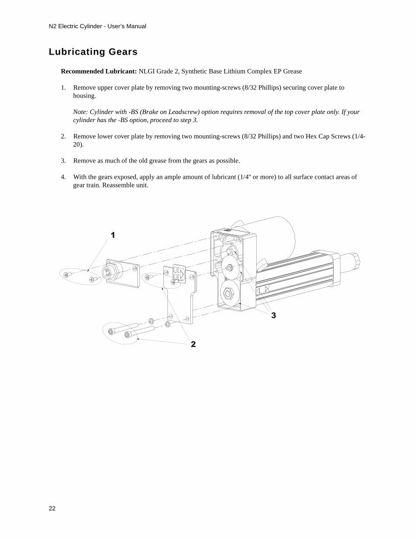
Lubricating Gears
Recommended Lubricant: NLGI Grade 2, Synthetic Base Lithium Complex EP Grease
1. Remove upper cover plate by removing two mounting-screws (8/32 Phillips) securing cover plate to housing.
Note: Cylinder with -BS (Brake on Leadscrew) option requires removal of the top cover plate only. If your cylinder has the -BS option, proceed to step 3.
2. Remove lower cover plate by removing two mounting-screws (8/32 Phillips) and two Hex Cap Screws (1/4-20).
3. Remove as much of the old grease from the gears as possible.
4. With the gears exposed, apply an ample amount of lubricant (1/4'' or more) to all surface contact areas of gear train. Reassemble unit.
1
2
3
N2 Electric Cylinder - User’s Manual
23
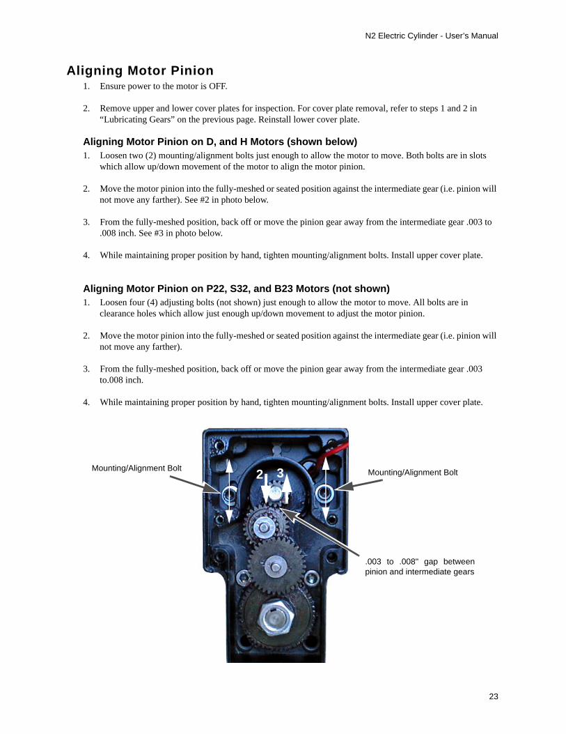
Aligning Motor Pinion1. Ensure power to the motor is OFF.
2. Remove upper and lower cover plates for inspection. For cover plate removal, refer to steps 1 and 2 in “Lubricating Gears” on the previous page. Reinstall lower cover plate.
Aligning Motor Pinion on D, and H Motors (shown below)1. Loosen two (2) mounting/alignment bolts just enough to allow the motor to move. Both bolts are in slots
which allow up/down movement of the motor to align the motor pinion.
2. Move the motor pinion into the fully-meshed or seated position against the intermediate gear (i.e. pinion will not move any farther). See #2 in photo below.
3. From the fully-meshed position, back off or move the pinion gear away from the intermediate gear .003 to .008 inch. See #3 in photo below.
4. While maintaining proper position by hand, tighten mounting/alignment bolts. Install upper cover plate.
Aligning Motor Pinion on P22, S32, and B23 Motors (not shown)1. Loosen four (4) adjusting bolts (not shown) just enough to allow the motor to move. All bolts are in
clearance holes which allow just enough up/down movement to adjust the motor pinion.
2. Move the motor pinion into the fully-meshed or seated position against the intermediate gear (i.e. pinion will not move any farther).
3. From the fully-meshed position, back off or move the pinion gear away from the intermediate gear .003 to.008 inch.
4. While maintaining proper position by hand, tighten mounting/alignment bolts. Install upper cover plate.
Mounting/Alignment Bolt Mounting/Alignment Bolt2 3
.003 to .008'' gap betweenpinion and intermediate gears
N2 Electric Cylinder - User’s Manual
24
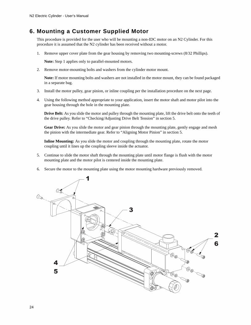
6. Mounting a Customer Supplied MotorThis procedure is provided for the user who will be mounting a non-IDC motor on an N2 Cylinder. For this procedure it is assumed that the N2 cylinder has been received without a motor.
1. Remove upper cover plate from the gear housing by removing two mounting-screws (8/32 Phillips).
Note: Step 1 applies only to parallel-mounted motors.
2. Remove motor-mounting bolts and washers from the cylinder motor mount.
Note: If motor mounting bolts and washers are not installed in the motor mount, they can be found packaged in a separate bag.
3. Install the motor pulley, gear pinion, or inline coupling per the installation procedure on the next page.
4. Using the following method appropriate to your application, insert the motor shaft and motor pilot into the gear housing through the hole in the mounting plate.
Drive Belt: As you slide the motor and pulley through the mounting plate, lift the drive belt onto the teeth of the drive pulley. Refer to “Checking/Adjusting Drive Belt Tension” in section 5.
Gear Drive: As you slide the motor and gear pinion through the mounting plate, gently engage and mesh the pinion with the intermediate gear. Refer to “Aligning Motor Pinion” in section 5.
Inline Mounting: As you slide the motor and coupling through the mounting plate, rotate the motor coupling until it lines up the coupling sleeve inside the actuator.
5. Continue to slide the motor shaft through the mounting plate until motor flange is flush with the motor mounting plate and the motor pilot is centered inside the mounting plate.
6. Secure the motor to the mounting plate using the motor mounting hardware previously removed.
1
2
6
3
4
5
N2 Electric Cylinder - User’s Manual
25
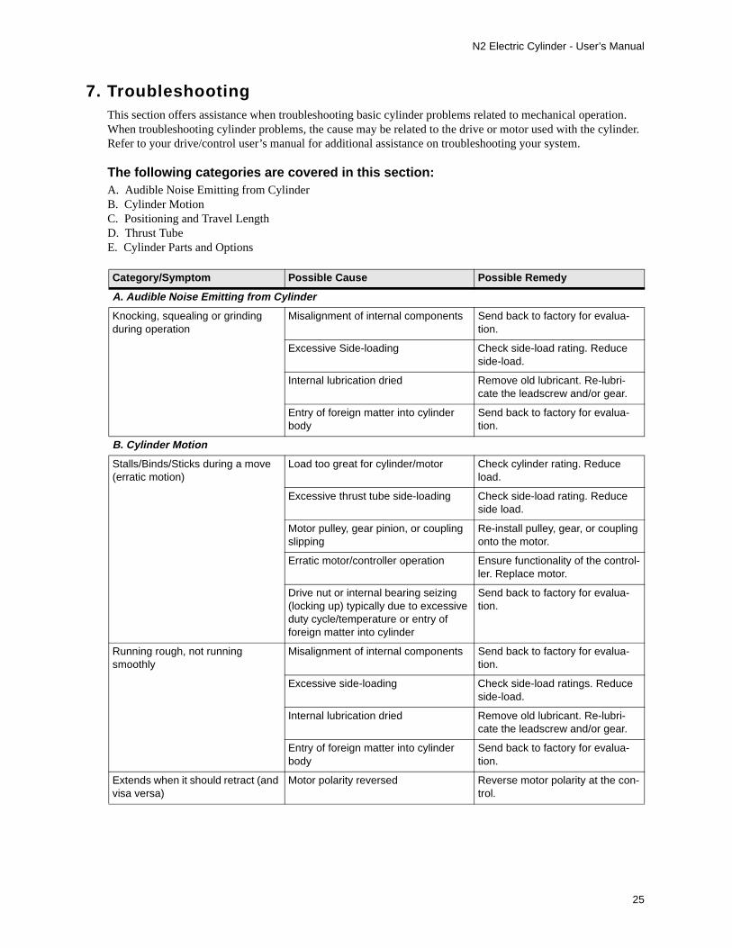
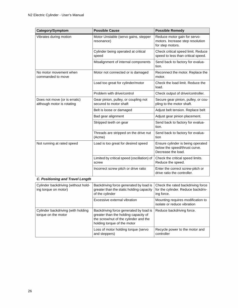
7. TroubleshootingThis section offers assistance when troubleshooting basic cylinder problems related to mechanical operation. When troubleshooting cylinder problems, the cause may be related to the drive or motor used with the cylinder. Refer to your drive/control user’s manual for additional assistance on troubleshooting your system.
The following categories are covered in this section:A. Audible Noise Emitting from CylinderB. Cylinder MotionC. Positioning and Travel LengthD. Thrust TubeE. Cylinder Parts and Options
Category/Symptom Possible Cause Possible Remedy
A. Audible Noise Emitting from Cylinder
Knocking, squealing or grinding during operation
Misalignment of internal components Send back to factory for evalua-tion.
Excessive Side-loading Check side-load rating. Reduce side-load.
Internal lubrication dried Remove old lubricant. Re-lubri-cate the leadscrew and/or gear.
Entry of foreign matter into cylinder body
Send back to factory for evalua-tion.
B. Cylinder Motion
Stalls/Binds/Sticks during a move (erratic motion)
Load too great for cylinder/motor Check cylinder rating. Reduce load.
Excessive thrust tube side-loading Check side-load rating. Reduce side load.
Motor pulley, gear pinion, or coupling slipping
Re-install pulley, gear, or coupling onto the motor.
Erratic motor/controller operation Ensure functionality of the control-ler. Replace motor.
Drive nut or internal bearing seizing (locking up) typically due to excessive duty cycle/temperature or entry of foreign matter into cylinder
Send back to factory for evalua-tion.
Running rough, not running smoothly
Misalignment of internal components Send back to factory for evalua-tion.
Excessive side-loading Check side-load ratings. Reduce side-load.
Internal lubrication dried Remove old lubricant. Re-lubri-cate the leadscrew and/or gear.
Entry of foreign matter into cylinder body
Send back to factory for evalua-tion.
Extends when it should retract (and visa versa)
Motor polarity reversed Reverse motor polarity at the con-trol.
N2 Electric Cylinder - User’s Manual
26
Vibrates during motion Motor Unstable (servo gains, stepper resonance)
Reduce motor gain for servo-motors. Increase step resolution for step motors.
Cylinder being operated at critical speed
Check critical speed limit. Reduce speed to less than critical speed.
Misalignment of internal components Send back to factory for evalua-tion.
No motor movement when commanded to move
Motor not connected or is damaged Reconnect the motor. Replace the motor.
Load too great for cylinder/motor Check the load limit. Reduce the load.
Problem with drive/control Check output of drive/controller.
Does not move (or is erratic) although motor is rotating
Gear pinion, pulley, or coupling not secured to motor shaft
Secure gear pinion, pulley, or cou-pling to the motor shaft.
Belt is loose or damaged Adjust belt tension. Replace belt
Bad gear alignment Adjust gear pinion placement.
Stripped teeth on gear Send back to factory for evalua-tion.
Threads are stripped on the drive nut (Acme)
Send back to factory for evalua-tion
Not running at rated speed Load is too great for desired speed Ensure cylinder is being operated below the speed/thrust curve. Decrease the load.
Limited by critical speed (oscillation) of screw
Check the critical speed limits. Reduce the speed.
Incorrect screw pitch or drive ratio Enter the correct screw-pitch or drive ratio the controller.
C. Positioning and Travel Length
Cylinder backdriving (without hold-ing torque on motor)
Backdriving force generated by load is greater than the static holding capacity of the cylinder
Check the rated backdriving force for the cylinder. Reduce backdriv-ing force.
Excessive external vibration Mounting requires modification to isolate or reduce vibration
Cylinder backdriving (with holding torque on the motor
Backdriving force generated by load is greater than the holding capacity of the screw/nut of the cylinder and the holding torque of the motor
Reduce backdriving force.
Loss of motor holding torque (servo and steppers)
Recycle power to the motor and controller
Category/Symptom Possible Cause Possible Remedy

N2 Electric Cylinder - User’s Manual
27
Not enough travel Position-Sensors reducing “actual” travel
Adjust sensors to increase cylin-der travel without allowing cylinder to hit its internal hard-stop bumper.
Cylinder option (e.g. -DB option) may be limiting stroke. -DB (Double Bear-ing) option reduces usable cylinder travel by 1.5 inches.
Return cylinder to factory for mod-ification (remove -DB option).Your application may require a cyl-inder with longer travel.
Excessive side-loading Check side-load rating for the cyl-inder. Reduce side-load.
Customer mounting is physically limiting travel
Re-design mounting
Expected linear travel distance notcorresponding to number of motor revs
Incorrect screw pitch or drive ratio Check screw-pitch and drive ratio of the cylinder. Enter correct pitch and ratio in the controller
Incorrect scaling factor (programmable controllers)
Enter correct scaling factor in the controller
Expected stop position not repeat-able (in same direction)
Load varies from cycle to cycle. Change load to be more consis-tent from cycle to cycle
Erratic Motor/Control operation Contact motor/control vendor for more information.
D. Thrust Tube
Wobbles during extension Leadscrew or thrust tube is bent Send back to factory for evalua-tion
Excessive wear on leadscrew/nut Send back to factory for evalua-tion
Improper mounting of cylinder Ensure cylinder travel is aligned with the travel of the load
Deflects too much during extension (Excessive lateral endplay)
Leadscrew/nut or internal bearings are worn
Send back to factory for evalua-tion
Excessive side-loading Check side-load rating. Reduce side load.
Improper cylinder mounting Ensure that cylinder travel is in line with the travel of the load
Bent thrust tube Load too great for cylinderSend back to factory for evalua-tion
Excessive side-loading
Improper cylinder mounting
Rotates (excessive radial play) Internal guide flange is damaged Send back to factory for evalua-tion
Thrust tube not fully engaged on drivenut
Rotate thrust tube clockwise until it stops turning. The maximum torque exerted on the thrust tube is 50 ft. lbs.
Category/Symptom Possible Cause Possible Remedy

N2 Electric Cylinder - User’s Manual
28
Stuck in fully extended or retracted position
Drive nut physically jammed into end of travel
Remove both rear covers and rotate the leadscrew, gear, pulley, or coupling until the leadscrew turns freely. If jammed in extend, rotate CW. If jammed in retract, rotate CCW.
Load too great for cylinder/motor Check cylinder load rating. Reduce load
Excessive side loading Check side-load rating. Reduce side-load.
Pulley, gear, or coupling slipping Re-install pulley, gear, or coupling onto the motor.
Erratic motor/drive operation Contact motor/drive vendor for more information
Excessive axial endplay (system backlash)
Leadscrew/nut is worn Send back to factory for evalua-tion
Gears worn Send back to factory for evalua-tion
Belt stretching Re-tension belt
E. Cylinder Parts and Options
Driving belt breaking or gears stripping
Motor torque is too great Reduce Accel and Decel
Reduce load
Motor accel/decel too great for given load
Reduce Accel or Decel
Load is too great for cylinder Check load rating of cylinder. Reduce load.
Excessive shock loading (running into physical hardstop, rapid change in direction)
Reduce Accel/Decel of cylinder. Stop motion just before the hard stop.
Position Sensors not being acti-vated by internal magnet
Misalignment of internal components Send back to factory for evalua-tion
Weak or missing internal magnet Send back to factory for evalua-tion
Switch/sensor is damaged or miswired Check/correct switch wiring
Send back to factory for evalua-tion
Cylinder speed too fast Reduce cylinder speed
Linear Potentiometer (LP) not reading properly
LPO wiper lifting off track (misalign-ment or LP bending due to excessive load
Ensure cylinder travel is in line with travel of the load
Reduce load
Damaged / contaminated LP (by liquid/particle)
Send back to factory for evalua-tion
Category/Symptom Possible Cause Possible Remedy

N2 Electric Cylinder - User’s Manual
29
Motor overheating Duty cycle too high Check duty cycle rating. Reduce duty cycle
High ambient temperature Use an external fan to cool the motor
Incorrect current setting on drive Check the control/drive user’s manual for correct current set-tings. Reset the control/drive with correct current setting.
Brake not holding load Brake not coupled to motor or lead-screw properly
Send back to factory for evalua-tion
Load exceeds holding capacity of cyl-inder/brake
Check brake load rating. Reduce the load.
Brake damaged Send back to factory for evalua-tion
Brake wired incorrectly Check wiring and make correc-tions or repairs
Encoder reading improperly Encoder damaged Send back to factory for evalua-tion
Encoder wired incorrectly Check wiring and make correc-tions or repairs
Incorrect supply voltage to encoder Check encoder voltage rating. Ensure correct voltage is supplied to the encoder.
Category/Symptom Possible Cause Possible Remedy

N2 Electric Cylinder - User’s Manual
30
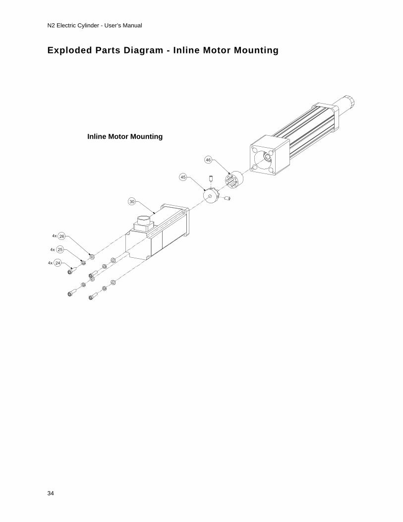
8. Parts List and Exploded Parts DiagramsParts can be ordered through your local IDC distributor. Kits include all essential parts and instructions. Item numbers below correspond with numbered items on the Exploded Parts Diagrams (see following pages).
Reference # on Exploded Parts
DiagramDescription of Part
1 Nut, Jam, Rear
2 Key, Pulley, Gear, or Coupling
3 Pulley (Driven), Gear (Driven), or Coupling (Driven)
4 Bearing, Leadscrew
5 Bearing Spacer
6 Drive Housing
7 Drive Nut
8 Guide Flange Body
9 Guide Flange Bushings
10 Magnet, Limit Switch
11 Leadscrew
12 Washer
13 Bumper
14 Bushing, Leadscrew
15 Nut, Jam, Front
16 Bolt, Guide Cylinder, Upper, Rear
17 Thrust Tube
18 Spacer, Bumper (Optional)
19 Rod End
20 Guide Cylinder
21 Assembly, Rod End Housing
22 Bolt, Guide Cylinder, Front
23 Belt, Timing
24 Bolt, Motor Mounting
25 Washer, Lock, Motor Mounting
26 Washer, Motor Mounting
27 Plate, Motor Mounting
28 Screw, Motor Mounting Plate
29 Drive Pulley or Gear Pinion
30 Motor
31 Brushes, Motor
32 Bolt, Guide Cylinder, Lower, Rear
33 Washer, Lock, Guide Cylinder Bolts
34 Label, IDC Decal
35 Screw, Rear Cover Plate
36 Quick Disconnect
37 Plate, Cover, Lower
38 Plate, Cover, Upper
39 Label, IDC Serial Tag
40 Label, Limit Switch (Positioning Sensor)
41 Assembly, Gear, First Stage
42 Assembly, Gear, Second Stage
43 Snap Ring, Internal
44 Bolt, Guide Cylinder, Rear
45 Coupling, Drive
46 Sleeve, Coupling

N2 Electric Cylinder - User’s Manual
31
Exploded Parts Diagram - Parallel Motor Mounting
1
2
3
4
5
6
4
7
9 10
8
9
11
12
1314
12
15
2x 16
17
1819
20
21
22 4x
2xParallel M otor M ounti ng

N2 Electric Cylinder - User’s Manual
32
Exploded Parts Diagram - Parallel Motor Mounting
2x 26
2x
2x 25
24
23
39
27
4x 28
29
30
31 2x
29
41
40
42
3
37
33 2x
32 2x
34
4x 35
36
38
Parallel Motor Mounting

N2 Electric Cylinder - User’s Manual
33
Exploded Parts Diagram - Inline Motor Mounting
2
4
5
1
3
9
8
11
9
10
13
12
12
14
15
43
6
4
7
17
22 4x
21
20
19
18
444x
Inline Motor Mounting
N2 Electric Cylinder - User’s Manual
34
Exploded Parts Diagram - Inline Motor Mounting
4x 26
4x 25
4x 24
30
45
46
Inline Motor Mounting

N2 Electric Cylinder - User’s Manual
35
9. Warranty and Service CoverageIndustrial Devices Corporation warrants all N2 Cylinders to be free of defects in material & workmanship for a period of one year from the date of shipment to the user. Products returned prepaid to the factory will be repaired or replaced at our option at no charge, and returned prepaid to the user.
Products that fail due to improper use or misapplication are not subject to the terms of this warranty.
Technic al SupportIndustrial Devices offers technical support through its factory authorized and trained Distributors, and through its factory-based Applications Engineering and Inside Sales department.
If an application problem exists or if the product has failed, contact your Distributor or Industrial Devices for technical assistance. Contact our factory at 1-800-747-0064, outside the U.S. at 707-789-1000.
Factory Repair ServiceProduct repairs are performed at our factory in Petaluma, California. Prior approval by Industrial Devices is required before returning a product for any reason. All returned products must be accompanied by an Industrial Devices supplied RMA (Return Material Authorization) number.
In Case of Failure1. Get the Model and Serial Number of the defective unit, and document the nature of the failure using the RMA
Data Form to help us repair the unit. 2. Prepare a purchase order for the repair cost in case the unit is out of warranty. 3. Contact your IDC Distributor or Industrial Devices Corporation (at 1-800-747-0064) for an RMA#.4. Ship the unit prepaid, with the RMA number and documentation to:
Industrial Devices Co., LLC3925 Cypress DrivePetaluma, CA 94954Attn.: RMA # ___________

Industrial Devices Corporation3925 Cypress DrivePetaluma, CA USA 94954TEL: (800) 747-0064 • FAX: (707) 789-0175 • OUTSIDE THE U.S. CALL (707) 789-1000E-mail: [email protected] Web Site: www.idcmotion.com


