108
GF Piping Systems Industrial Polyethylene Piping System Technical Manual
GF Piping SystemsGF Piping Systems
Industrial Polyethylene Piping System
Technical Manual

3Industrial PE Technical Handbook 2016
Table of ContentsSection 1: Overview . . . . . . . . . . . . . . . . . . . . . . . . . . . . . . . . . .9Overview . . . . . . . . . . . . . . . . . . . . . . . . . . . . . . . . . . . . . . . . . . . . . . . . . . . . . . . . . . . . . . . . . . . . . . . . . . . . . . . . . . . . . 9
General Information . . . . . . . . . . . . . . . . . . . . . . . . . . . . . . . . . . . . . . . . . . . . . . . . . . . . . . . . . . . . . . . . . . . . . . . . . . . . . . . . . . . . . . . . . . . . . . . . 9
Mechanical Properties . . . . . . . . . . . . . . . . . . . . . . . . . . . . . . . . . . . . . . . . . . . . . . . . . . . . . . . . . . . . . . . . . . . . . . . . . . . . . . . . . . . . . . . . . . . . . . 9
Chemical, Weathering and Abrasion Resistance . . . . . . . . . . . . . . . . . . . . . . . . . . . . . . . . . . . . . . . . . . . . . . . . . . . . . . . . . . . . . . . . . . . . . . . 9
Thermal Properties . . . . . . . . . . . . . . . . . . . . . . . . . . . . . . . . . . . . . . . . . . . . . . . . . . . . . . . . . . . . . . . . . . . . . . . . . . . . . . . . . . . . . . . . . . . . . . . 10
Combustion Behavior . . . . . . . . . . . . . . . . . . . . . . . . . . . . . . . . . . . . . . . . . . . . . . . . . . . . . . . . . . . . . . . . . . . . . . . . . . . . . . . . . . . . . . . . . . . . . . 10
Electrical Properties . . . . . . . . . . . . . . . . . . . . . . . . . . . . . . . . . . . . . . . . . . . . . . . . . . . . . . . . . . . . . . . . . . . . . . . . . . . . . . . . . . . . . . . . . . . . . . 10
Resin . . . . . . . . . . . . . . . . . . . . . . . . . . . . . . . . . . . . . . . . . . . . . . . . . . . . . . . . . . . . . . . . . . . . . . . . . . . . . . . . . . . . . . . . . . . . . . . . . . . . . . . . . . . . 10
Complete System of Pipe, Valves and Fittings . . . . . . . . . . . . . . . . . . . . . . . . . . . . . . . . . . . . . . . . . . . . . . . . . . . . . . . . . . . . . . . . . . . . . . . . . 11
Reliable Fusion Joining . . . . . . . . . . . . . . . . . . . . . . . . . . . . . . . . . . . . . . . . . . . . . . . . . . . . . . . . . . . . . . . . . . . . . . . . . . . . . . . . . . . . . . . . . . . . 11
Electrofusion Joining . . . . . . . . . . . . . . . . . . . . . . . . . . . . . . . . . . . . . . . . . . . . . . . . . . . . . . . . . . . . . . . . . . . . . . . . . . . . . . . . . . . . . . . . . . . . . . 11
CNC Controlled (Conventional) Contact Butt Fusion Joining . . . . . . . . . . . . . . . . . . . . . . . . . . . . . . . . . . . . . . . . . . . . . . . . . . . . . . . . . . . . . 12
Conventional contact butt fusion . . . . . . . . . . . . . . . . . . . . . . . . . . . . . . . . . . . . . . . . . . . . . . . . . . . . . . . . . . . . . . . . . . . . . . . . . . . . . . . . . . . . 12
General Properties . . . . . . . . . . . . . . . . . . . . . . . . . . . . . . . . . . . . . . . . . . . . . . . . . . . . . . . . . . . . . . . . . . . . . . . . . . . 13Material Data . . . . . . . . . . . . . . . . . . . . . . . . . . . . . . . . . . . . . . . . . . . . . . . . . . . . . . . . . . . . . . . . . . . . . . . . . . . . . . . . . . . . . . . . . . . . . . . . . . . . . 13
Mechanical Connections . . . . . . . . . . . . . . . . . . . . . . . . . . . . . . . . . . . . . . . . . . . . . . . . . . . . . . . . . . . . . . . . . . . . . . . . . . . . . . 14
Threaded Connections . . . . . . . . . . . . . . . . . . . . . . . . . . . . . . . . . . . . . . . . . . . . . . . . . . . . . . . . . . . . . . . . . . . . . . . . 14
Flanged Connections . . . . . . . . . . . . . . . . . . . . . . . . . . . . . . . . . . . . . . . . . . . . . . . . . . . . . . . . . . . . . . . . . . . . . . . . . 14Creating Flange Joints . . . . . . . . . . . . . . . . . . . . . . . . . . . . . . . . . . . . . . . . . . . . . . . . . . . . . . . . . . . . . . . . . . . . . . . . . . . . . . . . . . . . . . . . . . . . . 14
Gaskets . . . . . . . . . . . . . . . . . . . . . . . . . . . . . . . . . . . . . . . . . . . . . . . . . . . . . . . . . . . . . . . . . . . . . . . . . . . . . . . . . . . . . . . . . . . . . . . . . . . . . . . . . 15
Fasteners . . . . . . . . . . . . . . . . . . . . . . . . . . . . . . . . . . . . . . . . . . . . . . . . . . . . . . . . . . . . . . . . . . . . . . . . . . . . . . . . . . . . . . . . . . . . . . . . . . . . . . . . 15
Torque Wrench . . . . . . . . . . . . . . . . . . . . . . . . . . . . . . . . . . . . . . . . . . . . . . . . . . . . . . . . . . . . . . . . . . . . . . . . . . . . . . . . . . . . . . . . . . . . . . . . . . . 16
Checking System Alignment . . . . . . . . . . . . . . . . . . . . . . . . . . . . . . . . . . . . . . . . . . . . . . . . . . . . . . . . . . . . . . . . . . . . . . . . . . . . . . . . . . . . . . . 17
Bolt Hole Alignment . . . . . . . . . . . . . . . . . . . . . . . . . . . . . . . . . . . . . . . . . . . . . . . . . . . . . . . . . . . . . . . . . . . . . . . . . . . . . . . . . . . . . . . . . . . . . . . 18
Placing the Gasket . . . . . . . . . . . . . . . . . . . . . . . . . . . . . . . . . . . . . . . . . . . . . . . . . . . . . . . . . . . . . . . . . . . . . . . . . . . . . . . . . . . . . . . . . . . . . . . . 18
Inserting the Bolts . . . . . . . . . . . . . . . . . . . . . . . . . . . . . . . . . . . . . . . . . . . . . . . . . . . . . . . . . . . . . . . . . . . . . . . . . . . . . . . . . . . . . . . . . . . . . . . . 18
Tightening the Bolts . . . . . . . . . . . . . . . . . . . . . . . . . . . . . . . . . . . . . . . . . . . . . . . . . . . . . . . . . . . . . . . . . . . . . . . . . . . . . . . . . . . . . . . . . . . . . . 19
Documentation for Flanged Connections . . . . . . . . . . . . . . . . . . . . . . . . . . . . . . . . . . . . . . . . . . . . . . . . . . . . . . . . 21Keep Instructions Available . . . . . . . . . . . . . . . . . . . . . . . . . . . . . . . . . . . . . . . . . . . . . . . . . . . . . . . . . . . . . . . . . . . . . . . . . . . . . . . . . . . . . . . . 21
Creating Union Joints . . . . . . . . . . . . . . . . . . . . . . . . . . . . . . . . . . . . . . . . . . . . . . . . . . . . . . . . . . . . . . . . . . . . . . . . . 22Introduction . . . . . . . . . . . . . . . . . . . . . . . . . . . . . . . . . . . . . . . . . . . . . . . . . . . . . . . . . . . . . . . . . . . . . . . . . . . . . . . . . . . . . . . . . . . . . . . . . . . . . . 22
Valve Support . . . . . . . . . . . . . . . . . . . . . . . . . . . . . . . . . . . . . . . . . . . . . . . . . . . . . . . . . . . . . . . . . . . . . . . . . . . . . . . . . . . . . . . . . . . . . . . . . . . . 22
System Alignment . . . . . . . . . . . . . . . . . . . . . . . . . . . . . . . . . . . . . . . . . . . . . . . . . . . . . . . . . . . . . . . . . . . . . . . . . . . . . . . . . . . . . . . . . . . . . . . . 22
Sealing Mechanism . . . . . . . . . . . . . . . . . . . . . . . . . . . . . . . . . . . . . . . . . . . . . . . . . . . . . . . . . . . . . . . . . . . . . . . . . . . . . . . . . . . . . . . . . . . . . . . 22
Dirt and Debris . . . . . . . . . . . . . . . . . . . . . . . . . . . . . . . . . . . . . . . . . . . . . . . . . . . . . . . . . . . . . . . . . . . . . . . . . . . . . . . . . . . . . . . . . . . . . . . . . . . 22
Installation . . . . . . . . . . . . . . . . . . . . . . . . . . . . . . . . . . . . . . . . . . . . . . . . . . . . . . . . . . . . . . . . . . . . . . . . . . . . . . . . . . . . . . . . . . . . . . . . . . . . . . 22
End Connectors . . . . . . . . . . . . . . . . . . . . . . . . . . . . . . . . . . . . . . . . . . . . . . . . . . . . . . . . . . . . . . . . . . . . . . . . . . . . . . . . . . . . . . . . . . . . . . . . . . 22
Solvent Cementing . . . . . . . . . . . . . . . . . . . . . . . . . . . . . . . . . . . . . . . . . . . . . . . . . . . . . . . . . . . . . . . . . . . . . . . . . . . . . . . . . . . . . . . . . . . . . . . . 22
O-Ring Placement . . . . . . . . . . . . . . . . . . . . . . . . . . . . . . . . . . . . . . . . . . . . . . . . . . . . . . . . . . . . . . . . . . . . . . . . . . . . . . . . . . . . . . . . . . . . . . . . 22
Union Connection . . . . . . . . . . . . . . . . . . . . . . . . . . . . . . . . . . . . . . . . . . . . . . . . . . . . . . . . . . . . . . . . . . . . . . . . . . . . . . . . . . . . . . . . . . . . . . . . . 22
Hand-Tightening (all sizes) (see Table 4) . . . . . . . . . . . . . . . . . . . . . . . . . . . . . . . . . . . . . . . . . . . . . . . . . . . . . . . . . . . . . . . . . . . . . . . . . . . . . 23
Optional: Further Tightening (2”) . . . . . . . . . . . . . . . . . . . . . . . . . . . . . . . . . . . . . . . . . . . . . . . . . . . . . . . . . . . . . . . . . . . . . . . . . . . . . . . . . . . . 23
Post-Test Tightening (Sizes ½” to 1½” only) . . . . . . . . . . . . . . . . . . . . . . . . . . . . . . . . . . . . . . . . . . . . . . . . . . . . . . . . . . . . . . . . . . . . . . . . . . 23
Quality Check After Assembly . . . . . . . . . . . . . . . . . . . . . . . . . . . . . . . . . . . . . . . . . . . . . . . . . . . . . . . . . . . . . . . . . . . . . . . . . . . . . . . . . . . . . . 23
4 Industrial PE Technical Handbook 2016
Documentation for Union Joints . . . . . . . . . . . . . . . . . . . . . . . . . . . . . . . . . . . . . . . . . . . . . . . . . . . . . . . . . . . . . . . 24
Creating Threaded Joints . . . . . . . . . . . . . . . . . . . . . . . . . . . . . . . . . . . . . . . . . . . . . . . . . . . . . . . . . . . . . . . . . . . . . 25Introduction . . . . . . . . . . . . . . . . . . . . . . . . . . . . . . . . . . . . . . . . . . . . . . . . . . . . . . . . . . . . . . . . . . . . . . . . . . . . . . . . . . . . . . . . . . . . . . . . . . . . . . 25
Design Considerations . . . . . . . . . . . . . . . . . . . . . . . . . . . . . . . . . . . . . . . . . . . . . . . . . . . . . . . . . . . . . . . . . . . . . . . . . . . . . . . . . . . . . . . . . . . . 25
Preparation - Thread Sealant . . . . . . . . . . . . . . . . . . . . . . . . . . . . . . . . . . . . . . . . . . . . . . . . . . . . . . . . . . . . . . . . . . . . . . . . . . . . . . . . . . . . . . 25
Installation - Thread Sealant . . . . . . . . . . . . . . . . . . . . . . . . . . . . . . . . . . . . . . . . . . . . . . . . . . . . . . . . . . . . . . . . . . . . . . . . . . . . . . . . . . . . . . . 25
Making the Connection . . . . . . . . . . . . . . . . . . . . . . . . . . . . . . . . . . . . . . . . . . . . . . . . . . . . . . . . . . . . . . . . . . . . . . . . . . . . . . . . . . . . . . . . . . . . 25
Alignment . . . . . . . . . . . . . . . . . . . . . . . . . . . . . . . . . . . . . . . . . . . . . . . . . . . . . . . . . . . . . . . . . . . . . . . . . . . . . . . . . . . . . . . . . . . . . . . . . . . . . . . 25
Electrofusion - Overview . . . . . . . . . . . . . . . . . . . . . . . . . . . . . . . . . . . . . . . . . . . . . . . . . . . . . . . . . . . . . . . . . . . . . . 26Electrofusion Joining Method . . . . . . . . . . . . . . . . . . . . . . . . . . . . . . . . . . . . . . . . . . . . . . . . . . . . . . . . . . . . . . . . . . . . . . . . . . . . . . . . . . . . . . . 26
General Requirements . . . . . . . . . . . . . . . . . . . . . . . . . . . . . . . . . . . . . . . . . . . . . . . . . . . . . . . . . . . . . . . . . . . . . . . . . . . . . . . . . . . . . . . . . . . . . 26
Storage and Handling . . . . . . . . . . . . . . . . . . . . . . . . . . . . . . . . . . . . . . . . . . . . . . . . . . . . . . . . . . . . . . . . . . . . . . . . . . . . . . . . . . . . . . . . . . . . . . 26
Fusion Equipment . . . . . . . . . . . . . . . . . . . . . . . . . . . . . . . . . . . . . . . . . . . . . . . . . . . . . . . . . . . . . . . . . . . . . . . . . . . . . . . . . . . . . . . . . . . . . . . . . 27
Pipe Preparation Equipment . . . . . . . . . . . . . . . . . . . . . . . . . . . . . . . . . . . . . . . . . . . . . . . . . . . . . . . . . . . . . . . . . . . . . . . . . . . . . . . . . . . . . . . . 28
Pipe Restraint Equipment . . . . . . . . . . . . . . . . . . . . . . . . . . . . . . . . . . . . . . . . . . . . . . . . . . . . . . . . . . . . . . . . . . . . . . . . . . . . . . . . . . . . . . . . . . 28
Fusion Indicators (ecoFIT Metric only) . . . . . . . . . . . . . . . . . . . . . . . . . . . . . . . . . . . . . . . . . . . . . . . . . . . . . . . . . . . . . . . . . . . . . . . . . . . . . . . 28
Fusion Process . . . . . . . . . . . . . . . . . . . . . . . . . . . . . . . . . . . . . . . . . . . . . . . . . . . . . . . . . . . . . . . . . . . . . . . . . . . . . . . . . . . . . . . . . . . . . . . . . . . 29
CNC Controlled (Conventional) Contact Butt Fusion - Overview . . . . . . . . . . . . . . . . . . . . . . . . . . . . . . . . . . . . . 30Butt Fusion Joining Method . . . . . . . . . . . . . . . . . . . . . . . . . . . . . . . . . . . . . . . . . . . . . . . . . . . . . . . . . . . . . . . . . . . . . . . . . . . . . . . . . . . . . . . . . 30
General Requirements . . . . . . . . . . . . . . . . . . . . . . . . . . . . . . . . . . . . . . . . . . . . . . . . . . . . . . . . . . . . . . . . . . . . . . . . . . . . . . . . . . . . . . . . . . . . . 30
Storage and Handling . . . . . . . . . . . . . . . . . . . . . . . . . . . . . . . . . . . . . . . . . . . . . . . . . . . . . . . . . . . . . . . . . . . . . . . . . . . . . . . . . . . . . . . . . . . . . . 30
Fusion Equipment . . . . . . . . . . . . . . . . . . . . . . . . . . . . . . . . . . . . . . . . . . . . . . . . . . . . . . . . . . . . . . . . . . . . . . . . . . . . . . . . . . . . . . . . . . . . . . . . . 31
IR Plus® Infrared Non-contact Butt Fusion . . . . . . . . . . . . . . . . . . . . . . . . . . . . . . . . . . . . . . . . . . . . . . . . . . . . . . . 32
Section 2: IPS . . . . . . . . . . . . . . . . . . . . . . . . . . . . . . . . . . . . . . .33System Specification - Design Flow™ Piping Systems in IPS/DIPS Polyethylene (PE) . . . . . . . . . . . . . . . . . . . . . . 33
Pressure/Temperature . . . . . . . . . . . . . . . . . . . . . . . . . . . . . . . . . . . . . . . . . . . . . . . . . . . . . . . . . . . . . . . . . . . . . . . 37Long-Term Stress . . . . . . . . . . . . . . . . . . . . . . . . . . . . . . . . . . . . . . . . . . . . . . . . . . . . . . . . . . . . . . . . . . . . . . . . . . . . . . . . . . . . . . . . . . . . . . . . . 37
Working Pressures and Temperatures for PE100 Pipe and Fittings . . . . . . . . . . . . . . . . . . . . . . . . . . . . . . . . . . . . . . . . . . . . . . . . . . . . . 38
Dimensional Pipe Size - SDR . . . . . . . . . . . . . . . . . . . . . . . . . . . . . . . . . . . . . . . . . . . . . . . . . . . . . . . . . . . . . . . . . . . 39
Calculating Pipe Size . . . . . . . . . . . . . . . . . . . . . . . . . . . . . . . . . . . . . . . . . . . . . . . . . . . . . . . . . . . . . . . . . . . . . . . . . 40Friction Loss Characteristics . . . . . . . . . . . . . . . . . . . . . . . . . . . . . . . . . . . . . . . . . . . . . . . . . . . . . . . . . . . . . . . . . . . . . . . . . . . . . . . . . . . . . . . 40
Hazen and Williams Formula . . . . . . . . . . . . . . . . . . . . . . . . . . . . . . . . . . . . . . . . . . . . . . . . . . . . . . . . . . . . . . . . . . . . . . . . . . . . . . . . . . . . . . . 40
C Factors . . . . . . . . . . . . . . . . . . . . . . . . . . . . . . . . . . . . . . . . . . . . . . . . . . . . . . . . . . . . . . . . . . . . . . . . . . . . . . . . . . . . . . . . . . . . . . . . . . . . . . . . . 40
Gravity Drain Systems . . . . . . . . . . . . . . . . . . . . . . . . . . . . . . . . . . . . . . . . . . . . . . . . . . . . . . . . . . . . . . . . . . . . . . . . 57Flow Rate for Gravity Drain Systems . . . . . . . . . . . . . . . . . . . . . . . . . . . . . . . . . . . . . . . . . . . . . . . . . . . . . . . . . . . . . . . . . . . . . . . . . . . . . . . . 57
Surge Pressure (Water Hammer) . . . . . . . . . . . . . . . . . . . . . . . . . . . . . . . . . . . . . . . . . . . . . . . . . . . . . . . . . . . . . . . 58Surge Pressure (Water Hammer) . . . . . . . . . . . . . . . . . . . . . . . . . . . . . . . . . . . . . . . . . . . . . . . . . . . . . . . . . . . . . . . . . . . . . . . . . . . . . . . . . . . 58
Special Consideration . . . . . . . . . . . . . . . . . . . . . . . . . . . . . . . . . . . . . . . . . . . . . . . . . . . . . . . . . . . . . . . . . . . . . . . . . . . . . . . . . . . . . . . . . . . . . 59
Example Problem . . . . . . . . . . . . . . . . . . . . . . . . . . . . . . . . . . . . . . . . . . . . . . . . . . . . . . . . . . . . . . . . . . . . . . . . . . . . . . . . . . . . . . . . . . . . . . . . . 60
Expansion/Contraction (Above Ground) . . . . . . . . . . . . . . . . . . . . . . . . . . . . . . . . . . . . . . . . . . . . . . . . . . . . . . . . . 62Allowing for Length Changes in PE Pipelines . . . . . . . . . . . . . . . . . . . . . . . . . . . . . . . . . . . . . . . . . . . . . . . . . . . . . . . . . . . . . . . . . . . . . . . . . 62
Calculation and Positioning of Flexible Sections . . . . . . . . . . . . . . . . . . . . . . . . . . . . . . . . . . . . . . . . . . . . . . . . . . . . . . . . . . . . . . . . . . . . . . 62
Type 1 - Offsets/Changes in Direction . . . . . . . . . . . . . . . . . . . . . . . . . . . . . . . . . . . . . . . . . . . . . . . . . . . . . . . . . . . . . . . . . . . . . . . . . . . . . . . 62
Type 2 -Expansion Loops . . . . . . . . . . . . . . . . . . . . . . . . . . . . . . . . . . . . . . . . . . . . . . . . . . . . . . . . . . . . . . . . . . . . . . . . . . . . . . . . . . . . . . . . . . . 63
Determining the Length Change (ΔL) (Example 1) . . . . . . . . . . . . . . . . . . . . . . . . . . . . . . . . . . . . . . . . . . . . . . . . . . . . . . . . . . . . . . . . . . . . . 63
Determining the Length of the Flexible Section (a) (Example 2) . . . . . . . . . . . . . . . . . . . . . . . . . . . . . . . . . . . . . . . . . . . . . . . . . . . . . . . . . 65
5Industrial PE Technical Handbook 2016
Installation Hints . . . . . . . . . . . . . . . . . . . . . . . . . . . . . . . . . . . . . . . . . . . . . . . . . . . . . . . . . . . . . . . . . . . . . . . . . . . . . . . . . . . . . . . . . . . . . . . . . . 67
Pre-Stressing . . . . . . . . . . . . . . . . . . . . . . . . . . . . . . . . . . . . . . . . . . . . . . . . . . . . . . . . . . . . . . . . . . . . . . . . . . . . . . . . . . . . . . . . . . . . . . . . . . . . 67
Installation . . . . . . . . . . . . . . . . . . . . . . . . . . . . . . . . . . . . . . . . . . . . . . . . . . . . . . . . . . . . . . . . . . . . . . . . . . . . . . . . . . 68The Incorporation of Valves . . . . . . . . . . . . . . . . . . . . . . . . . . . . . . . . . . . . . . . . . . . . . . . . . . . . . . . . . . . . . . . . . . . . . . . . . . . . . . . . . . . . . . . . 68
Vibration Dampeners . . . . . . . . . . . . . . . . . . . . . . . . . . . . . . . . . . . . . . . . . . . . . . . . . . . . . . . . . . . . . . . . . . . . . . . . . . . . . . . . . . . . . . . . . . . . . . 68
Pipe Bracket Support Centers and Fixation of Plastic Pipelines . . . . . . . . . . . . . . . . . . . . . . . . . . . . . . . . . . . . . . . . . . . . . . . . . . . . . . . . . 68
Hangers . . . . . . . . . . . . . . . . . . . . . . . . . . . . . . . . . . . . . . . . . . . . . . . . . . . . . . . . . . . . . . . . . . . . . . . . . . . . . . . . . . . . . . . . . . . . . . . . . . . . . . . . . 69
Pipe Sleeves . . . . . . . . . . . . . . . . . . . . . . . . . . . . . . . . . . . . . . . . . . . . . . . . . . . . . . . . . . . . . . . . . . . . . . . . . . . . . . . . . . . . . . . . . . . . . . . . . . . . . 69
Restraint . . . . . . . . . . . . . . . . . . . . . . . . . . . . . . . . . . . . . . . . . . . . . . . . . . . . . . . . . . . . . . . . . . . . . . . . . . . . . . . . . . . . 71
Cold Weather Installations . . . . . . . . . . . . . . . . . . . . . . . . . . . . . . . . . . . . . . . . . . . . . . . . . . . . . . . . . . . . . . . . . . . . 71
Flammability and Fire Rated Construction . . . . . . . . . . . . . . . . . . . . . . . . . . . . . . . . . . . . . . . . . . . . . . . . . . . . . . . 71Laboratory Fire Tests . . . . . . . . . . . . . . . . . . . . . . . . . . . . . . . . . . . . . . . . . . . . . . . . . . . . . . . . . . . . . . . . . . . . . . . . . . . . . . . . . . . . . . . . . . . . . . 71
ASTM D635 - Rate of Burning and/or Extent and Time of Burning of Self Supporting Plastics in a Horizontal Position . . . . . . . . . 71
UL94 - Standard for Safety of Flammability of Plastic Materials . . . . . . . . . . . . . . . . . . . . . . . . . . . . . . . . . . . . . . . . . . . . . . . . . . . . . . . . 71
ASTM D2843 - Density of Smoke from the Burning or Decomposition of Plastics . . . . . . . . . . . . . . . . . . . . . . . . . . . . . . . . . . . . . . . . . . 72
ASTM D2863 - Minimum Oxygen Concentration to Support Candle-Like Combustion of Plastics (Oxygen Index) . . . . . . . . . . . . . . . 72
Large Scale Tests . . . . . . . . . . . . . . . . . . . . . . . . . . . . . . . . . . . . . . . . . . . . . . . . . . . . . . . . . . . . . . . . . . . . . . . . . . . . . . . . . . . . . . . . . . . . . . . . 72
NFPA251 . . . . . . . . . . . . . . . . . . . . . . . . . . . . . . . . . . . . . . . . . . . . . . . . . . . . . . . . . . . . . . . . . . . . . . . . . . . . . . . . . . . . . . . . . . . . . . . . . . . . . . . . 72
Fire Protection Methods for Wall Penetration and Return Air Plenums . . . . . . . . . . . . . . . . . . . . . . . . . . . . . . . . . . . . . . . . . . . . . . . . . . . 72
Section 3: FM Factory Mutual . . . . . . . . . . . . . . . . . . . . . . . . .73Introduction . . . . . . . . . . . . . . . . . . . . . . . . . . . . . . . . . . . . . . . . . . . . . . . . . . . . . . . . . . . . . . . . . . . . . . . . . . . . . . . . . 73
Benefits and features . . . . . . . . . . . . . . . . . . . . . . . . . . . . . . . . . . . . . . . . . . . . . . . . . . . . . . . . . . . . . . . . . . . . . . . . 73
System Specification: Factory Mutual Approved Pipe and Fittings Model . . . . . . . . . . . . . . . . . . . . . . . . . . . . 75
Class Definition: CL150, CL200, CL267 . . . . . . . . . . . . . . . . . . . . . . . . . . . . . . . . . . . . . . . . . . . . . . . . . . . . . . . . . . 79
Internal/External Reinforcement Examples . . . . . . . . . . . . . . . . . . . . . . . . . . . . . . . . . . . . . . . . . . . . . . . . . . . . . . 79
Below Ground Installations . . . . . . . . . . . . . . . . . . . . . . . . . . . . . . . . . . . . . . . . . . . . . . . . . . . . . . . . . . . . . . . . . . . . 80Instruction for Underground Trenching . . . . . . . . . . . . . . . . . . . . . . . . . . . . . . . . . . . . . . . . . . . . . . . . . . . . . . . . . . . . . . . . . . . . . . . . . . . . . . 80
Bedding and Backfill Material . . . . . . . . . . . . . . . . . . . . . . . . . . . . . . . . . . . . . . . . . . . . . . . . . . . . . . . . . . . . . . . . . . . . . . . . . . . . . . . . . . . . . . . 80
Bedding and Backfilling - ASTM D2321 and D2774 . . . . . . . . . . . . . . . . . . . . . . . . . . . . . . . . . . . . . . . . . . . . . . . . . . . . . . . . . . . . . . . . . . . . 80
Mechanical Joint Anchor Fittings . . . . . . . . . . . . . . . . . . . . . . . . . . . . . . . . . . . . . . . . . . . . . . . . . . . . . . . . . . . . . . . 81
Section 4: Metric . . . . . . . . . . . . . . . . . . . . . . . . . . . . . . . . . . . .83System Specification - ecoFIT Piping Systems Metric Polyethylene (PE) . . . . . . . . . . . . . . . . . . . . . . . . . . . . . 83
Pressure/Temperature . . . . . . . . . . . . . . . . . . . . . . . . . . . . . . . . . . . . . . . . . . . . . . . . . . . . . . . . . . . . . . . . . . . . . . . 88Pressure/temperature diagram for PE 100 . . . . . . . . . . . . . . . . . . . . . . . . . . . . . . . . . . . . . . . . . . . . . . . . . . . . . . . . . . . . . . . . . . . . . . . . . . . 88
Pressure/temperature diagram for PE 80 . . . . . . . . . . . . . . . . . . . . . . . . . . . . . . . . . . . . . . . . . . . . . . . . . . . . . . . . . . . . . . . . . . . . . . . . . . . . 88
Comparison of nominal pressure for SDR17 and SDR17 .6 . . . . . . . . . . . . . . . . . . . . . . . . . . . . . . . . . . . . . . . . . 89Ascertaining the nominal pressure (PN) . . . . . . . . . . . . . . . . . . . . . . . . . . . . . . . . . . . . . . . . . . . . . . . . . . . . . . . . . . . . . . . . . . . . . . . . . . . . . 89
Minimum required strength (MRS) . . . . . . . . . . . . . . . . . . . . . . . . . . . . . . . . . . . . . . . . . . . . . . . . . . . . . . . . . . . . . . . . . . . . . . . . . . . . . . . . . . 89
Design stress (σS) . . . . . . . . . . . . . . . . . . . . . . . . . . . . . . . . . . . . . . . . . . . . . . . . . . . . . . . . . . . . . . . . . . . . . . . . . . . . . . . . . . . . . . . . . . . . . . . . . 89
Total operating (calculation) coefficient (C) . . . . . . . . . . . . . . . . . . . . . . . . . . . . . . . . . . . . . . . . . . . . . . . . . . . . . . . . . . . . . . . . . . . . . . . . . . . 89
Calculating Pipe Size . . . . . . . . . . . . . . . . . . . . . . . . . . . . . . . . . . . . . . . . . . . . . . . . . . . . . . . . . . . . . . . . . . . . . . . . . 90Friction Loss Characteristics . . . . . . . . . . . . . . . . . . . . . . . . . . . . . . . . . . . . . . . . . . . . . . . . . . . . . . . . . . . . . . . . . . . . . . . . . . . . . . . . . . . . . . . 90
Hazen and Williams Formula . . . . . . . . . . . . . . . . . . . . . . . . . . . . . . . . . . . . . . . . . . . . . . . . . . . . . . . . . . . . . . . . . . . . . . . . . . . . . . . . . . . . . . . 90
C Factors . . . . . . . . . . . . . . . . . . . . . . . . . . . . . . . . . . . . . . . . . . . . . . . . . . . . . . . . . . . . . . . . . . . . . . . . . . . . . . . . . . . . . . . . . . . . . . . . . . . . . . . . . 90
Surge Pressure (Water Hammer) . . . . . . . . . . . . . . . . . . . . . . . . . . . . . . . . . . . . . . . . . . . . . . . . . . . . . . . . . . . . . . . 91
6 Industrial PE Technical Handbook 2016
Surge Pressure (Water Hammer) . . . . . . . . . . . . . . . . . . . . . . . . . . . . . . . . . . . . . . . . . . . . . . . . . . . . . . . . . . . . . . . . . . . . . . . . . . . . . . . . . . . 91
Special Consideration . . . . . . . . . . . . . . . . . . . . . . . . . . . . . . . . . . . . . . . . . . . . . . . . . . . . . . . . . . . . . . . . . . . . . . . . . . . . . . . . . . . . . . . . . . . . . 92
Example Problem . . . . . . . . . . . . . . . . . . . . . . . . . . . . . . . . . . . . . . . . . . . . . . . . . . . . . . . . . . . . . . . . . . . . . . . . . . . . . . . . . . . . . . . . . . . . . . . . . 93
Expansion/Contraction . . . . . . . . . . . . . . . . . . . . . . . . . . . . . . . . . . . . . . . . . . . . . . . . . . . . . . . . . . . . . . . . . . . . . . . . 95Allowing for Length Changes in PE Pipelines . . . . . . . . . . . . . . . . . . . . . . . . . . . . . . . . . . . . . . . . . . . . . . . . . . . . . . . . . . . . . . . . . . . . . . . . . 95
Calculation and Positioning of Flexible Sections . . . . . . . . . . . . . . . . . . . . . . . . . . . . . . . . . . . . . . . . . . . . . . . . . . . . . . . . . . . . . . . . . . . . . . 95
Type 1 - Offsets/Changes in Direction . . . . . . . . . . . . . . . . . . . . . . . . . . . . . . . . . . . . . . . . . . . . . . . . . . . . . . . . . . . . . . . . . . . . . . . . . . . . . . . 95
Type 2 -Expansion Loops . . . . . . . . . . . . . . . . . . . . . . . . . . . . . . . . . . . . . . . . . . . . . . . . . . . . . . . . . . . . . . . . . . . . . . . . . . . . . . . . . . . . . . . . . . . 96
Determining the Length Change (ΔL) (Example 1) . . . . . . . . . . . . . . . . . . . . . . . . . . . . . . . . . . . . . . . . . . . . . . . . . . . . . . . . . . . . . . . . . . . . . 96
Determining the Length of the Flexible Section (a) (Example 2) . . . . . . . . . . . . . . . . . . . . . . . . . . . . . . . . . . . . . . . . . . . . . . . . . . . . . . . . . 98
Installation Hints . . . . . . . . . . . . . . . . . . . . . . . . . . . . . . . . . . . . . . . . . . . . . . . . . . . . . . . . . . . . . . . . . . . . . . . . . . . . . . . . . . . . . . . . . . . . . . . . . 100
Pre-Stressing . . . . . . . . . . . . . . . . . . . . . . . . . . . . . . . . . . . . . . . . . . . . . . . . . . . . . . . . . . . . . . . . . . . . . . . . . . . . . . . . . . . . . . . . . . . . . . . . . . . 100
Installation . . . . . . . . . . . . . . . . . . . . . . . . . . . . . . . . . . . . . . . . . . . . . . . . . . . . . . . . . . . . . . . . . . . . . . . . . . . . . . . . . 101The Incorporation of Valves . . . . . . . . . . . . . . . . . . . . . . . . . . . . . . . . . . . . . . . . . . . . . . . . . . . . . . . . . . . . . . . . . . . . . . . . . . . . . . . . . . . . . . . 101
Vibration Dampeners . . . . . . . . . . . . . . . . . . . . . . . . . . . . . . . . . . . . . . . . . . . . . . . . . . . . . . . . . . . . . . . . . . . . . . . . . . . . . . . . . . . . . . . . . . . . . 101
Pipe Bracket Support Centers and Fixation of Plastic Pipelines . . . . . . . . . . . . . . . . . . . . . . . . . . . . . . . . . . . . . . . . . . . . . . . . . . . . . . . . 101
Hangers . . . . . . . . . . . . . . . . . . . . . . . . . . . . . . . . . . . . . . . . . . . . . . . . . . . . . . . . . . . . . . . . . . . . . . . . . . . . . . . . . . . . . . . . . . . . . . . . . . . . . . . . 102
Pipe Sleeves . . . . . . . . . . . . . . . . . . . . . . . . . . . . . . . . . . . . . . . . . . . . . . . . . . . . . . . . . . . . . . . . . . . . . . . . . . . . . . . . . . . . . . . . . . . . . . . . . . . . 102
Restraint . . . . . . . . . . . . . . . . . . . . . . . . . . . . . . . . . . . . . . . . . . . . . . . . . . . . . . . . . . . . . . . . . . . . . . . . . . . . . . . . . . . 104
Cold Weather Installations . . . . . . . . . . . . . . . . . . . . . . . . . . . . . . . . . . . . . . . . . . . . . . . . . . . . . . . . . . . . . . . . . . . 104
Flammability and Fire Rated Construction . . . . . . . . . . . . . . . . . . . . . . . . . . . . . . . . . . . . . . . . . . . . . . . . . . . . . . 104Laboratory Fire Tests . . . . . . . . . . . . . . . . . . . . . . . . . . . . . . . . . . . . . . . . . . . . . . . . . . . . . . . . . . . . . . . . . . . . . . . . . . . . . . . . . . . . . . . . . . . . . 104
ASTM D635 - Rate of Burning and/or Extent and Time of Burning of Self Supporting Plastics in a Horizontal Position . . . . . . . . 104
UL94 - Standard for Safety of Flammability of Plastic Materials . . . . . . . . . . . . . . . . . . . . . . . . . . . . . . . . . . . . . . . . . . . . . . . . . . . . . . . 104
ASTM D2843 - Density of Smoke from the Burning or Decomposition of Plastics . . . . . . . . . . . . . . . . . . . . . . . . . . . . . . . . . . . . . . . . . 105
ASTM D2863 - Minimum Oxygen Concentration to Support Candle-Like Combustion of Plastics (Oxygen Index) . . . . . . . . . . . . . . 105
Large Scale Tests . . . . . . . . . . . . . . . . . . . . . . . . . . . . . . . . . . . . . . . . . . . . . . . . . . . . . . . . . . . . . . . . . . . . . . . . . . . . . . . . . . . . . . . . . . . . . . . 105
NFPA251 . . . . . . . . . . . . . . . . . . . . . . . . . . . . . . . . . . . . . . . . . . . . . . . . . . . . . . . . . . . . . . . . . . . . . . . . . . . . . . . . . . . . . . . . . . . . . . . . . . . . . . . 105
Fire Protection Methods for Wall Penetration and Return Air Plenums . . . . . . . . . . . . . . . . . . . . . . . . . . . . . . . . . . . . . . . . . . . . . . . . . . 105
7Industrial PE Technical Handbook 2016
TablesTable 1 - Flange Size . . . . . . . . . . . . . . . . . . . . . . . . . . . . . . . . . . . . . . . . . . . . . . . . . . . . . . . . . . . . . . . . . . . . . . . . . . . . . . . . . . . . . . . . . . . . . . 15
Table 2 - Fastener Specifications . . . . . . . . . . . . . . . . . . . . . . . . . . . . . . . . . . . . . . . . . . . . . . . . . . . . . . . . . . . . . . . . . . . . . . . . . . . . . . . . . . . 16
Table 3 - Multiple Pass Bolt Torque . . . . . . . . . . . . . . . . . . . . . . . . . . . . . . . . . . . . . . . . . . . . . . . . . . . . . . . . . . . . . . . . . . . . . . . . . . . . . . . . . 20
Table 4 - Tightening Guide for Union and Ball Valve Nuts . . . . . . . . . . . . . . . . . . . . . . . . . . . . . . . . . . . . . . . . . . . . . . . . . . . . . . . . . . . . . . 23
Table 5 - Threaded Connection Guide . . . . . . . . . . . . . . . . . . . . . . . . . . . . . . . . . . . . . . . . . . . . . . . . . . . . . . . . . . . . . . . . . . . . . . . . . . . . . . . 25
Table 6 - Pipe Size Comparison . . . . . . . . . . . . . . . . . . . . . . . . . . . . . . . . . . . . . . . . . . . . . . . . . . . . . . . . . . . . . . . . . . . . . . . . . . . . . . . . . . . . . 39
Table 7 - Flow Rate vs . Friction Loss - IPS SDR 7 . . . . . . . . . . . . . . . . . . . . . . . . . . . . . . . . . . . . . . . . . . . . . . . . . . . . . . . . . . . . . . . . . . . . . 41
Table 8 - Flow Rate vs . Friction Loss - IPS SDR 9 . . . . . . . . . . . . . . . . . . . . . . . . . . . . . . . . . . . . . . . . . . . . . . . . . . . . . . . . . . . . . . . . . . . . . 43
Table 9 - Flow Rate vs . Friction Loss - IPS SDR 11 . . . . . . . . . . . . . . . . . . . . . . . . . . . . . . . . . . . . . . . . . . . . . . . . . . . . . . . . . . . . . . . . . . . . 45
Table 10 - Flow Rate vs . Friction Loss - IPS SDR 17 . . . . . . . . . . . . . . . . . . . . . . . . . . . . . . . . . . . . . . . . . . . . . . . . . . . . . . . . . . . . . . . . . . . 48
Table 11 - Flow Rate vs . Friction Loss - DIPS DR 11 . . . . . . . . . . . . . . . . . . . . . . . . . . . . . . . . . . . . . . . . . . . . . . . . . . . . . . . . . . . . . . . . . . . 51
Table 12 - Flow Rate vs . Friction Loss - DIPS DR 17 . . . . . . . . . . . . . . . . . . . . . . . . . . . . . . . . . . . . . . . . . . . . . . . . . . . . . . . . . . . . . . . . . . . 53
Table 13 - Friction Loss Through Fittings - Equivalent Length of Pipe (ft .) . . . . . . . . . . . . . . . . . . . . . . . . . . . . . . . . . . . . . . . . . . . . . . . 56
Table 14 - Approximate Discharge Rates and Velocities in Sloping Drains Flowing Half-Full . . . . . . . . . . . . . . . . . . . . . . . . . . . . . . . 57
Table 15 - Length Change of Straight Pipe (ΔL) in Inches . . . . . . . . . . . . . . . . . . . . . . . . . . . . . . . . . . . . . . . . . . . . . . . . . . . . . . . . . . . . . . 64
Table 16 - Length of Flexible Sections (a) in Inches . . . . . . . . . . . . . . . . . . . . . . . . . . . . . . . . . . . . . . . . . . . . . . . . . . . . . . . . . . . . . . . . . . . 66
Table 17 - General Pipe Supports and Brackets for Liquids with a Specific Gravity ≤ 1 .0 (62 .4 lb/ft3) . . . . . . . . . . . . . . . . . . . . . . . . 70
Table 18 - Overview of GF Piping Systems products with FM approval (IPS & DIPS diameters) . . . . . . . . . . . . . . . . . . . . . . . . . . . . . 74
Table 19 - Comparison of your FM solutions for underground fire protection systems . . . . . . . . . . . . . . . . . . . . . . . . . . . . . . . . . . . . 74
Table 20 - Soil Load and Pipe Resistance . . . . . . . . . . . . . . . . . . . . . . . . . . . . . . . . . . . . . . . . . . . . . . . . . . . . . . . . . . . . . . . . . . . . . . . . . . . . 82
Table 21 - Length Change of Straight Pipe (ΔL) in Inches . . . . . . . . . . . . . . . . . . . . . . . . . . . . . . . . . . . . . . . . . . . . . . . . . . . . . . . . . . . . . . 97
Table 22 - Length of Flexible Sections (a) in Inches . . . . . . . . . . . . . . . . . . . . . . . . . . . . . . . . . . . . . . . . . . . . . . . . . . . . . . . . . . . . . . . . . . . 99
Table 23 - General Pipe Supports and Brackets for Liquids with a Specific Gravity ≤ 1 .0 (62 .4 lb/ft3) . . . . . . . . . . . . . . . . . . . . . . . 103
8 Industrial PE Technical Handbook 2016
FiguresFigure 1 - Electrofusion Coupling . . . . . . . . . . . . . . . . . . . . . . . . . . . . . . . . . . . . . . . . . . . . . . . . . . . . . . . . . . . . . . . . . . . . . . . . . . . . . . . . . . . 11
Figure 2 - Gasket Dimensions . . . . . . . . . . . . . . . . . . . . . . . . . . . . . . . . . . . . . . . . . . . . . . . . . . . . . . . . . . . . . . . . . . . . . . . . . . . . . . . . . . . . . . 15
Figure 3 - Pinch Test . . . . . . . . . . . . . . . . . . . . . . . . . . . . . . . . . . . . . . . . . . . . . . . . . . . . . . . . . . . . . . . . . . . . . . . . . . . . . . . . . . . . . . . . . . . . . . 17
Figure 4 - Gap Test . . . . . . . . . . . . . . . . . . . . . . . . . . . . . . . . . . . . . . . . . . . . . . . . . . . . . . . . . . . . . . . . . . . . . . . . . . . . . . . . . . . . . . . . . . . . . . . 17
Figure 5 - Alignment Test . . . . . . . . . . . . . . . . . . . . . . . . . . . . . . . . . . . . . . . . . . . . . . . . . . . . . . . . . . . . . . . . . . . . . . . . . . . . . . . . . . . . . . . . . . 17
Figure 6 - Flange Orientation . . . . . . . . . . . . . . . . . . . . . . . . . . . . . . . . . . . . . . . . . . . . . . . . . . . . . . . . . . . . . . . . . . . . . . . . . . . . . . . . . . . . . . 18
Figure 7 - Flange Assembly . . . . . . . . . . . . . . . . . . . . . . . . . . . . . . . . . . . . . . . . . . . . . . . . . . . . . . . . . . . . . . . . . . . . . . . . . . . . . . . . . . . . . . . 18
Figure 8 - Proper Thread Engagement . . . . . . . . . . . . . . . . . . . . . . . . . . . . . . . . . . . . . . . . . . . . . . . . . . . . . . . . . . . . . . . . . . . . . . . . . . . . . . 18
Figure 9 - Recommended Bolt Tightening Sequence . . . . . . . . . . . . . . . . . . . . . . . . . . . . . . . . . . . . . . . . . . . . . . . . . . . . . . . . . . . . . . . . . . 19
Figure 10 - Flange Installation . . . . . . . . . . . . . . . . . . . . . . . . . . . . . . . . . . . . . . . . . . . . . . . . . . . . . . . . . . . . . . . . . . . . . . . . . . . . . . . . . . . . . 21
Figure 11 - Union Installation . . . . . . . . . . . . . . . . . . . . . . . . . . . . . . . . . . . . . . . . . . . . . . . . . . . . . . . . . . . . . . . . . . . . . . . . . . . . . . . . . . . . . . 24
Figure 12 - Long-Term Stress . . . . . . . . . . . . . . . . . . . . . . . . . . . . . . . . . . . . . . . . . . . . . . . . . . . . . . . . . . . . . . . . . . . . . . . . . . . . . . . . . . . . . . 37
Figure 13 - Regression Curve . . . . . . . . . . . . . . . . . . . . . . . . . . . . . . . . . . . . . . . . . . . . . . . . . . . . . . . . . . . . . . . . . . . . . . . . . . . . . . . . . . . . . . 37
Figure 14 - Pressure/Temperature Curve . . . . . . . . . . . . . . . . . . . . . . . . . . . . . . . . . . . . . . . . . . . . . . . . . . . . . . . . . . . . . . . . . . . . . . . . . . . 38
Figure 15 - Hazen Williams Formula . . . . . . . . . . . . . . . . . . . . . . . . . . . . . . . . . . . . . . . . . . . . . . . . . . . . . . . . . . . . . . . . . . . . . . . . . . . . . . . . 40
Figure 16 - Pressure Wave . . . . . . . . . . . . . . . . . . . . . . . . . . . . . . . . . . . . . . . . . . . . . . . . . . . . . . . . . . . . . . . . . . . . . . . . . . . . . . . . . . . . . . . . 58
Figure 17 - Modulus of Elasticity of Plastics . . . . . . . . . . . . . . . . . . . . . . . . . . . . . . . . . . . . . . . . . . . . . . . . . . . . . . . . . . . . . . . . . . . . . . . . . 62
Figure 18 - Changes in Direction . . . . . . . . . . . . . . . . . . . . . . . . . . . . . . . . . . . . . . . . . . . . . . . . . . . . . . . . . . . . . . . . . . . . . . . . . . . . . . . . . . . 62
Figure 19 - Offsets . . . . . . . . . . . . . . . . . . . . . . . . . . . . . . . . . . . . . . . . . . . . . . . . . . . . . . . . . . . . . . . . . . . . . . . . . . . . . . . . . . . . . . . . . . . . . . . . 62
Figure 20 - Expansion Loop . . . . . . . . . . . . . . . . . . . . . . . . . . . . . . . . . . . . . . . . . . . . . . . . . . . . . . . . . . . . . . . . . . . . . . . . . . . . . . . . . . . . . . . . 63
Figure 21 - Recommended Hangers for Plastic Piping Systems . . . . . . . . . . . . . . . . . . . . . . . . . . . . . . . . . . . . . . . . . . . . . . . . . . . . . . . . 69
Figure 23 - Pipe Sleeves . . . . . . . . . . . . . . . . . . . . . . . . . . . . . . . . . . . . . . . . . . . . . . . . . . . . . . . . . . . . . . . . . . . . . . . . . . . . . . . . . . . . . . . . . . . 69
Figure 22 - Typical Brackets and Anchor Arrangements . . . . . . . . . . . . . . . . . . . . . . . . . . . . . . . . . . . . . . . . . . . . . . . . . . . . . . . . . . . . . . 70
Figure 24 - Underground Trench Examples . . . . . . . . . . . . . . . . . . . . . . . . . . . . . . . . . . . . . . . . . . . . . . . . . . . . . . . . . . . . . . . . . . . . . . . . . . 80
Figure 25 - Hazen Williams Formula . . . . . . . . . . . . . . . . . . . . . . . . . . . . . . . . . . . . . . . . . . . . . . . . . . . . . . . . . . . . . . . . . . . . . . . . . . . . . . . . 90
Figure 26 - Pressure Wave . . . . . . . . . . . . . . . . . . . . . . . . . . . . . . . . . . . . . . . . . . . . . . . . . . . . . . . . . . . . . . . . . . . . . . . . . . . . . . . . . . . . . . . . 91
Figure 27 - Changes in Direction . . . . . . . . . . . . . . . . . . . . . . . . . . . . . . . . . . . . . . . . . . . . . . . . . . . . . . . . . . . . . . . . . . . . . . . . . . . . . . . . . . . 95
Figure 28 - Offsets . . . . . . . . . . . . . . . . . . . . . . . . . . . . . . . . . . . . . . . . . . . . . . . . . . . . . . . . . . . . . . . . . . . . . . . . . . . . . . . . . . . . . . . . . . . . . . . . 95
Figure 29 - Expansion Loop . . . . . . . . . . . . . . . . . . . . . . . . . . . . . . . . . . . . . . . . . . . . . . . . . . . . . . . . . . . . . . . . . . . . . . . . . . . . . . . . . . . . . . . . 96
Figure 30 - Recommended Hangers for Plastic Piping Systems . . . . . . . . . . . . . . . . . . . . . . . . . . . . . . . . . . . . . . . . . . . . . . . . . . . . . . . 102
Figure 31 - Pipe Sleeves . . . . . . . . . . . . . . . . . . . . . . . . . . . . . . . . . . . . . . . . . . . . . . . . . . . . . . . . . . . . . . . . . . . . . . . . . . . . . . . . . . . . . . . . . . 102
Figure 32 - Typical Brackets and Anchor Arrangements . . . . . . . . . . . . . . . . . . . . . . . . . . . . . . . . . . . . . . . . . . . . . . . . . . . . . . . . . . . . . 103
9Industrial PE Technical Handbook 2016
OverviewGeneral InformationPolymers which consist only of carbon and hydrogen (hydrocarbons) are called polyolefins . Polyethylene (PE) belongs to this group .
It is a semi-crystalline thermoplastic . Polyethylene is the best known standard polymer . The chemical formula is:
(CH2-CH
2)
n . It is an environmentally friendly hydrocarbon product .
PE is considered a non-polar material, meaning it does not dissolve in common solvents and hardly swells . As a result, PE pipes
cannot be solvent cemented . The appropriate joining method for this material is heat fusion . For piping installations, GF offers three
joining techniques in our product range: Electrofusion, Contact Butt Fusion and Infrared Butt Fusion .
The advantages of Polyethylene include
• Lower installed cost*
• Low weight
• Excellent impact resistance
• Outstanding flexibility
• Superior abrasion resistance
• Corrosion resistant
• Wide range of chemical compatibility
• Safe and easy joining by heat fusion *When compared to Stainless Steel and Large Diameter PVC
Mechanical PropertiesModern PE100 grades show a bimodal molecular weight distribution, i .e .: they consist of two different kinds of molecular chains
(short and long) . These polyethylenes combine a high tensile strength with a high resistance against fast and slow crack propagation .
PE also shows a very high impact resistance throughout its entire temperature range . For this test (Izod), a specimen is weakened
with a sharp notch and then struck . In doing this, the impact energy absorbed by the material is measured . This test proves that with
subsequent impact stress, polyethylene is not as susceptible to surface damage . A robust behavior like this, combined with an acute
resistance to fracture, is a significant advantage in applications where lower temperatures (down to -58°F) cause other thermoplastic
piping systems to become brittle .
Chemical, Weathering and Abrasion ResistanceDue to its non-polar nature as a hydrocarbon of high molecular weight, polyethylene shows a high resistance against chemical attack .
PE is resistant to acids, alkaline solutions, solvents, alcohol and water . Fat and oil swell PE slightly . PE is not resistant against
oxidizing acids, ketones, aromatic hydrocarbons and chlorinated hydrocarbons .
Experience has shown that PE offers considerable advantages over metal and other plastics, such as, low temperature applications
and excellent resistance against abrasion . As a result, PE piping systems are used in numerous applications for transporting brine
solutions, dissolved solids and slurries .
If Natural Polyethylene (not including additives) is exposed to direct sunlight over a long period of time, it will, like most natural and
plastic materials, be damaged by the combination of short wave UV and oxygen, causing photo-oxidation . To effectively address this
degradation phenomenon, carbon black additive is blended with resins to stabilize the material against UV exposure .
Section 1: Overview
10 Industrial PE Technical Handbook 2016
Thermal PropertiesPressurized polyethylene pipes can be used at temperatures ranging from -58°F to +140°F .
The thermal conductivity of PE100 is 2 .7 BTU-in/ft2/hr/°F . Because of its inherent insulating properties, a PE piping system is notably
more economical due to not requiring secondary insulation when compared to a system made of metals such as Stainless Steel and
Copper . This makes PE100/4710 pipe an excellent choice for chilled water systems .
Like all thermoplastics, PE shows a higher thermal expansion than metal . Our PE100/4710 has a coefficient of linear thermal
expansion of 1 .10 ×10-4 in/inºF . As long as this is taken into account during the planning of the installation, there should be no
problems with expansion or contraction requirements . Thermal strain management is important .
At higher temperatures, the tensile strength and stiffness of the material are reduced . Therefore, please consult the pressure-
temperature diagram (Figure 4) for further information .
Combustion BehaviorPolyethylene is considered a flammable plastic with oxygen index amounts to 17% . (Materials that burn with less than 21% of oxygen
in the air are considered to be flammable) . Below 17% O2 concentration, HDPE self-extinguishes .
PE drips and continues to burn without soot after the ignition source is removed . When PE burns, toxic substances; primarily carbon
dioxide and carbon monoxide, are released . Carbon monoxide is generally the combustion product most dangerous to humans .
The following classifications in accordance with different combustion standards are used: According to UL94, PE is classified as HB
(Horizontal Burning) . The self-ignition temperature is 662°F . Suitable fire-fighting agents are water, foam, carbon dioxide or powder .
Electrical PropertiesBecause of the low water absorption of PE, its electrical properties are hardly affected by continuous water contact .
PE is a non-polar hydrocarbon polymer that exhibits outstanding insulating qualities . These insulating properties can be reduced
considerably as a result of weathering, pollution or the effects of oxidizing media . The specific volume resistance is ›1013 Ωcm; the
dielectric strength is 500 V/mil .
Because of the possible development of electrostatic charges, caution is recommended when using PE in applications where the
danger of fires or explosion is magnified .
ResinUpdates and additions to ASTM D3350 caused the EHMW-HDPE resins designated as PE3408 in 2006, to become PE3608 in 2007 . The
HDPE material did not change, but the ASTM D3350 cell classification that described the material did change, necessitating the
upgrade to PE3608 . Those same changes encompassed the addition of PE4710 High Performance Polyethylene (HPPE) into the
arsenal of pipe grade resins . A PE4710 HPPE piping system can result in a 15% savings when compared to current costs of PE3408
piping systems . By virtue of its higher pressure rating enabling the use of the next lower DR, wall thickness becomes less, the pipe
I .D . increases and the weight per foot of pipe is reduced .
• PE3608 (prev . PE3408) Material Designation
Materials designated as PE3608 have a hydrostatic design basis of 1600 psi for water at 73°F . After applying the 0 .5 Design
Factor, the design working stress for 73°F is 800 psi .
• PE4710 (prev . PE3408) Material Designation
Materials designated as PE4710 have a hydrostatic design basis of 1600 psi for water at 73o F . After applying the 0 .63 Design
Factor, the design working stress for 73o F is 1000 psi . PE4710 has higher performance as described in PPI’s TN41 .
• PE100 Material Designation (ISO Pipe Material Designation Code)
The ISO pipe material designation code uses similar letters for the type of material as the ASTM code . Examples are PE for
polyethylene, PA for polyamide or PVC for poly vinyl chloride . These letters are followed by numbers that are simply the MRS
11Industrial PE Technical Handbook 2016
Complete System of Pipe, Valves and FittingsGF Piping Systems’ Polyethylene piping system easily transitions between PP and PVC and is available with pipes, fittings and
valves in IPS sizes from 2” to 42” .(For technical data on PP and PVC, please see GF‘s online technical data)
Ball valves (PP/PE) are available in sizes 2” to 4” . Diaphragm valves (PP/PE) are available in sizes 2” to 4” and butterfly valves in sizes
up to 24“ (metal external bodies with elastomer seals) . Other valves, including check valves and metering valves are also available
for this system .
This system includes all commonly required pressure pipe fittings, including threaded adaptors and flanges for ease of mating to
equipment or other piping materials . See product guide for details on full line of available products.
Reliable Fusion JoiningAssembly and joining of this system is performed by heat fusion . Fusion joints are made by heating and melting the pipe and fitting
together . This type of joint gives a homogeneous transition between the two components without the lowering of chemical resistance
associated with solvent cement joining and without the loss of integrity and loss of pressure handling ability of a threaded joint .
Three different fusion methods for GF Piping Systems’ PE100/4710 are available and commonly used in today‘s demanding
applications . These include socket, electrofusion, CNC controlled (conventional) contact butt fusion, and Infrared (IR) non-contact butt
fusion .
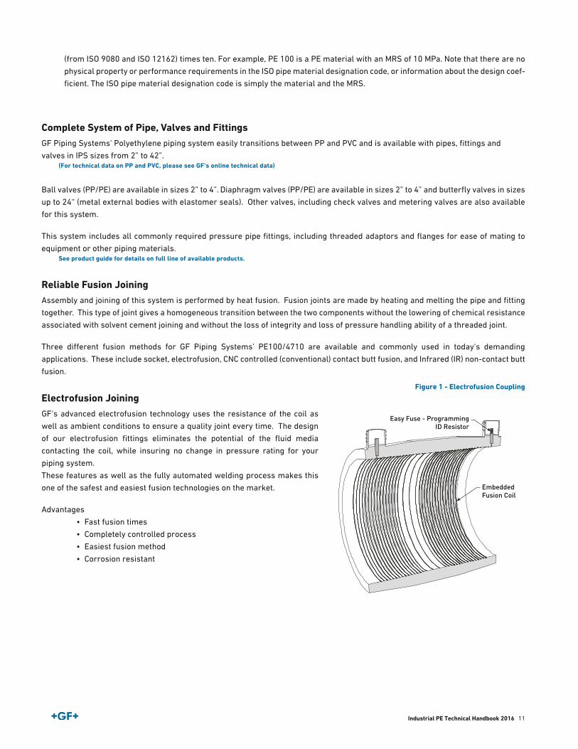
Electrofusion JoiningGF‘s advanced electrofusion technology uses the resistance of the coil as
well as ambient conditions to ensure a quality joint every time . The design
of our electrofusion fittings eliminates the potential of the fluid media
contacting the coil, while insuring no change in pressure rating for your
piping system .
These features as well as the fully automated welding process makes this
one of the safest and easiest fusion technologies on the market .
Advantages
• Fast fusion times
• Completely controlled process
• Easiest fusion method
• Corrosion resistant
Figure 1 - Electrofusion Coupling
(from ISO 9080 and ISO 12162) times ten . For example, PE 100 is a PE material with an MRS of 10 MPa . Note that there are no
physical property or performance requirements in the ISO pipe material designation code, or information about the design coef-
ficient . The ISO pipe material designation code is simply the material and the MRS .
Easy Fuse - ProgrammingID Resistor
EmbeddedFusion Coil
12 Industrial PE Technical Handbook 2016
CNC Controlled (Conventional) Contact Butt Fusion JoiningGF’s Contact Butt Fusion joining is an industry standard for sizes 2” to 24” .
Butt fusion pipe and fittings both have the same nominal inside and outside diameters . To make a butt fusion joint, the pipe and fitting
are clamped so that the ends to be joined are facing each other . The ends are then “faced” flat and parallel . A flat heating plate is used
to simultaneously heat both faces to be joined . When each end is molten, the heating plate is removed and the pipe and fitting are
brought together, joining the molten materials by fusion .
Advantages
• Repeatable weld parameters
• Controlled facing and joining pressure
• Automated fusion records
• Ease of operation due to CNC controller
• Eliminates operator dependant decisions
For information on Infrared Butt Fusion please contact your local GF distributor.
Conventional contact butt fusion GF’s Contact Butt Fusion joining is an industry standard for sizes 2” to 42” .
Butt fusion pipe and fittings both have the same nominal inside and outside diameters . To make a butt fusion joint, the pipe and fitting
are clamped so that the ends to be joined are facing each other . The ends are then “faced” flat and parallel . A flat heating plate is used
to simultaneously heat both faces to be joined . When each end is molten, the heating plate is removed and the pipe and fitting are
brought together, joining the molten materials by fusion .
13Industrial PE Technical Handbook 2016
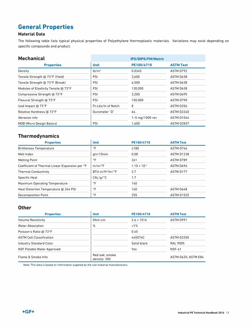
General PropertiesMaterial DataThe following table lists typical physical properties of Polyethylene thermoplastic materials . Variations may exist depending on
specific compounds and product .
Mechanical IPS/DIPS/FM/Metric
Properties Unit PE100/4710 ASTM Test
Density lb/in3 0 .0345 ASTM D792
Tensile Strength @ 73°F (Yield) PSI 3,600 ASTM D638
Tensile Strength @ 73°F (Break) PSI 4,500 ASTM D638
Modules of Elasticity Tensile @ 73°F PSI 130,000 ASTM D638
Compressive Strength @ 73°F PSI 3,200 ASTM D695
Flexural Strength @ 73°F PSI 150,000 ASTM D790
Izod Impact @ 73°F Ft-Lbs/In of Notch 8 ASTM D256
Relative Hardness @ 73°F Durometer “D” 64 ASTM D2240
Abrasion info 1–5 mg/1000 rev ASTM D1044
MDB (Micro Design Basics) PSI 1,600 ASTM D2837
ThermodynamicsProperties Unit PE100/4710 ASTM Test
Brittleness Temperature °F ≤180 ASTM D746
Melt Index gm/10min 0 .08 ASTM D1238
Melting Point °F 261 ASTM D789
Coefficient of Thermal Linear Expansion per °F in/in/°F 1 .10 × 10-4 ASTM D696
Thermal Conductivity BTU-in/ft2/hr/°F 2 .7 ASTM D177
Specific Heat CAL/g/°C 1 .7
Maximum Operating Temperature °F 140
Heat Distortion Temperature @ 264 PSI °F 160 ASTM D648
Decomposition Point °F 255 ASTM D1525
OtherProperties Unit PE100/4710 ASTM Test
Volume Resistivity Ohm-cm 2 .6 × 1016 ASTM D991
Water Absorption % <1%
Poisson’s Ratio @ 73°F 0 .45
ASTM Cell Classification 445574C ASTM D3350
Industry Standard Color Solid black RAL 9005
NSF Potable Water Approved Yes NSF-61
Flame & Smoke InfoRed oak; smoke density: 350
ASTM D635; ASTM E84
Note: This data is based on information supplied by the raw material manufacturers .
14 Industrial PE Technical Handbook 2016
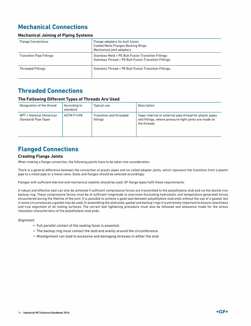
Mechanical Connections
Mechanical Joining of Piping SystemsFlange Connections Flange adapters for butt fusion
Coated Metal Flanges Backing RingsMechanical joint adapters
Transition Pipe Fittings Stainless Weld × PE Butt Fusion Transition FittingsStainless Thread × PE Butt Fusion Transition Fittings
Threaded Fittings Stainless Thread × PE Butt Fusion Transition Fittings
Threaded ConnectionsThe Following Different Types of Threads Are Used
Designation of the thread According to standard
Typical use Description
NPT = National (American Standard) Pipe Taper
ASTM F1498 Transition and threaded fittings
Taper internal or external pipe thread for plastic pipes and fittings, where pressure-tight joints are made on the threads
Flanged ConnectionsCreating Flange JointsWhen making a flange connection, the following points have to be taken into consideration:
There is a general difference between the connection of plastic pipes and so-called adapter joints, which represent the transition from a plastic pipe to a metal pipe or a metal valve . Seals and flanges should be selected accordingly .
Flanges with sufficient thermal and mechanical stability should be used . GF flange types fulfil these requirements .
A robust and effective seal can only be achieved if sufficient compressive forces are transmitted to the polyethylene stub end via the ductile iron backup ring . These compressive forces must be of sufficient magnitude to overcome fluctuating hydrostatic and temperature generated forces encountered during the lifetime of the joint . It is possible to achieve a good seal between polyethylene stub ends without the use of a gasket, but in some circumstances a gasket may be used . In assembling the stub ends, gasket and backup rings it is extremely important to ensure cleanliness and true alignment of all mating surfaces . The correct bolt tightening procedure must also be followed and allowance made for the stress relaxation characteristics of the polyethylene stub ends .
Alignment
• Full parallel contact of the sealing faces is essential .
• The backup ring must contact the stub end evenly around the circumference .
• Misalignment can lead to excessive and damaging stresses in either the stub
15Industrial PE Technical Handbook 2016
When to Use a Flange?Flanges may be used when:
• The piping system may need to be dismantled
• The installation is temporary or mobile
• Transitioning between dissimilar materials that can not be bonded togetherNote: Visually inspect flanges for cracks, deformities or other obstructions on the sealing surfaces.
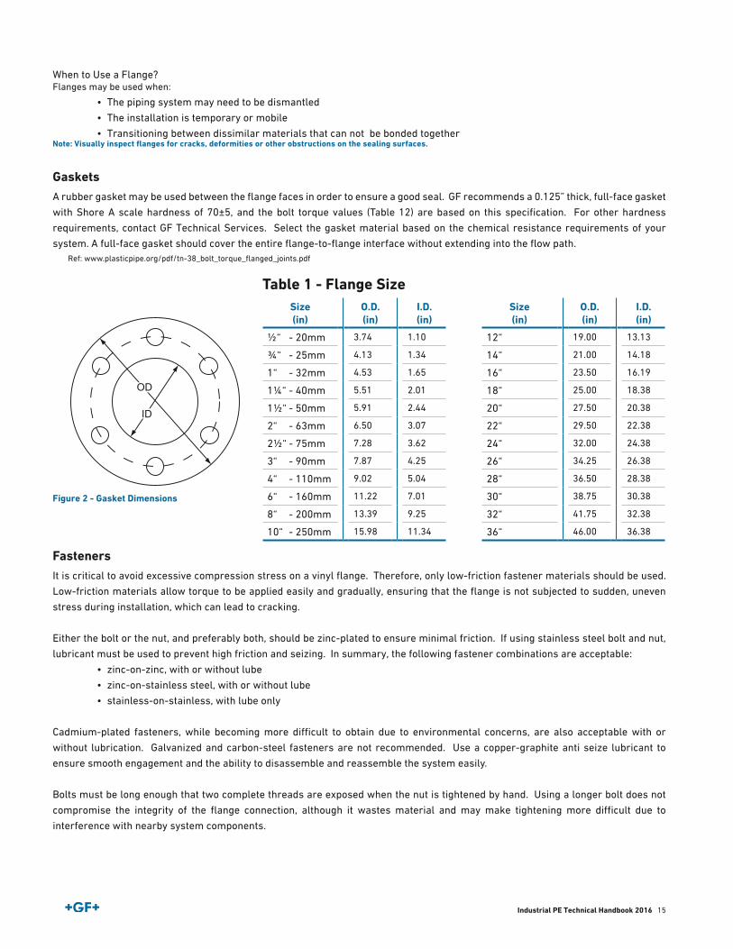
Gaskets A rubber gasket may be used between the flange faces in order to ensure a good seal . GF recommends a 0 .125” thick, full-face gasket
with Shore A scale hardness of 70±5, and the bolt torque values (Table 12) are based on this specification . For other hardness
requirements, contact GF Technical Services . Select the gasket material based on the chemical resistance requirements of your
system . A full-face gasket should cover the entire flange-to-flange interface without extending into the flow path . Ref: www .plasticpipe .org/pdf/tn-38_bolt_torque_flanged_joints .pdf
ID
OD
Figure 2 - Gasket Dimensions
Table 1 - Flange SizeSize (in)
O.D. (in)
I.D. (in)
Size (in)
O.D. (in)
I.D. (in)
½“ - 20mm 3 .74 1 .10 12“ 19 .00 13 .13
¾“ - 25mm 4 .13 1 .34 14“ 21 .00 14 .18
1“ - 32mm 4 .53 1 .65 16“ 23 .50 16 .19
1¼“ - 40mm 5 .51 2 .01 18“ 25 .00 18 .38
1½“ - 50mm 5 .91 2 .44 20“ 27 .50 20 .38
2“ - 63mm 6 .50 3 .07 22“ 29 .50 22 .38
2½“ - 75mm 7 .28 3 .62 24“ 32 .00 24 .38
3“ - 90mm 7 .87 4 .25 26“ 34 .25 26 .38
4“ - 110mm 9 .02 5 .04 28“ 36 .50 28 .38
6“ - 160mm 11 .22 7 .01 30“ 38 .75 30 .38
8“ - 200mm 13 .39 9 .25 32“ 41 .75 32 .38
10“ - 250mm 15 .98 11 .34 36“ 46 .00 36 .38
Fasteners It is critical to avoid excessive compression stress on a vinyl flange . Therefore, only low-friction fastener materials should be used .
Low-friction materials allow torque to be applied easily and gradually, ensuring that the flange is not subjected to sudden, uneven
stress during installation, which can lead to cracking .
Either the bolt or the nut, and preferably both, should be zinc-plated to ensure minimal friction . If using stainless steel bolt and nut,
lubricant must be used to prevent high friction and seizing . In summary, the following fastener combinations are acceptable:
• zinc-on-zinc, with or without lube
• zinc-on-stainless steel, with or without lube
• stainless-on-stainless, with lube only
Cadmium-plated fasteners, while becoming more difficult to obtain due to environmental concerns, are also acceptable with or
without lubrication . Galvanized and carbon-steel fasteners are not recommended . Use a copper-graphite anti seize lubricant to
ensure smooth engagement and the ability to disassemble and reassemble the system easily .
Bolts must be long enough that two complete threads are exposed when the nut is tightened by hand . Using a longer bolt does not
compromise the integrity of the flange connection, although it wastes material and may make tightening more difficult due to
interference with nearby system components .
16 Industrial PE Technical Handbook 2016
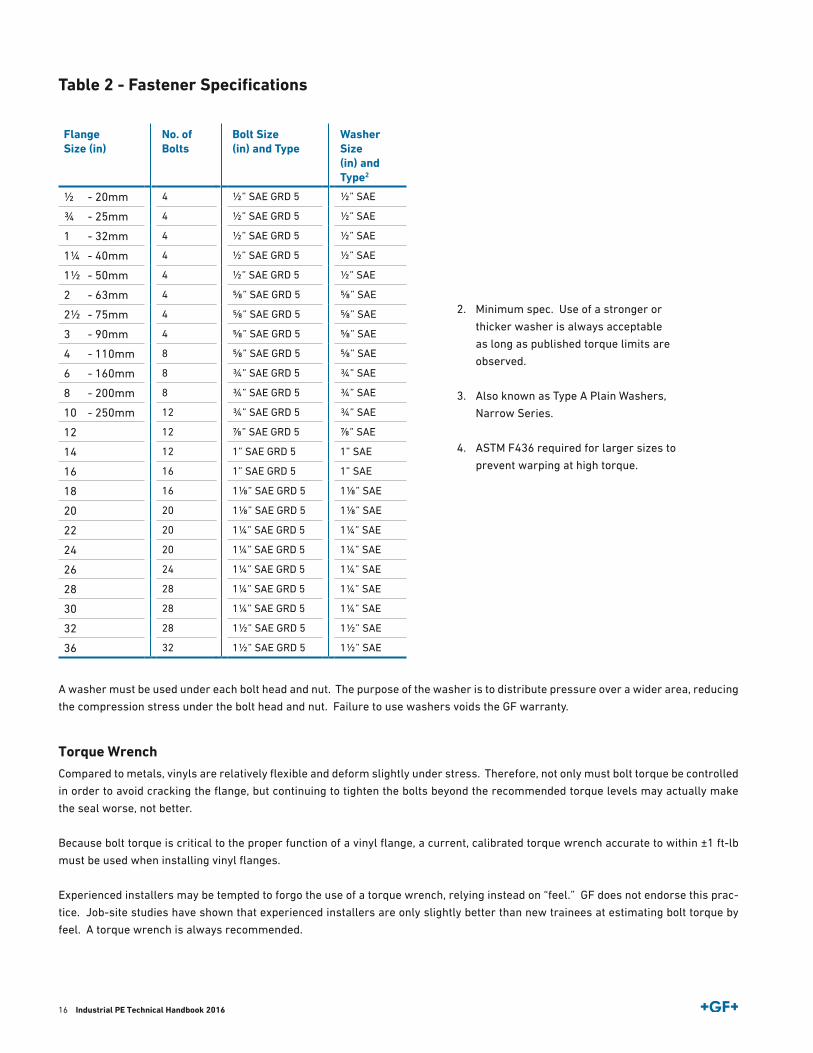
Table 2 - Fastener Specifications
FlangeSize (in)
No. ofBolts
Bolt Size(in) and Type
Washer Size(in) and Type2
½ - 20mm 4 ½” SAE GRD 5 ½” SAE
¾ - 25mm 4 ½” SAE GRD 5 ½” SAE
1 - 32mm 4 ½” SAE GRD 5 ½” SAE
1¼ - 40mm 4 ½” SAE GRD 5 ½” SAE
1½ - 50mm 4 ½” SAE GRD 5 ½” SAE
2 - 63mm 4 ⅝” SAE GRD 5 ⅝” SAE
2½ - 75mm 4 ⅝” SAE GRD 5 ⅝” SAE
3 - 90mm 4 ⅝” SAE GRD 5 ⅝” SAE
4 - 110mm 8 ⅝” SAE GRD 5 ⅝” SAE
6 - 160mm 8 ¾” SAE GRD 5 ¾” SAE
8 - 200mm 8 ¾” SAE GRD 5 ¾” SAE
10 - 250mm 12 ¾” SAE GRD 5 ¾” SAE
12 12 ⅞” SAE GRD 5 ⅞” SAE
14 12 1” SAE GRD 5 1” SAE
16 16 1” SAE GRD 5 1” SAE
18 16 1⅛” SAE GRD 5 1⅛” SAE
20 20 1⅛” SAE GRD 5 1⅛” SAE
22 20 1¼” SAE GRD 5 1¼” SAE
24 20 1¼” SAE GRD 5 1¼” SAE
26 24 1¼” SAE GRD 5 1¼” SAE
28 28 1¼” SAE GRD 5 1¼” SAE
30 28 1¼” SAE GRD 5 1¼” SAE
32 28 1½” SAE GRD 5 1½” SAE
36 32 1½” SAE GRD 5 1½” SAE
2 . Minimum spec . Use of a stronger or
thicker washer is always acceptable
as long as published torque limits are
observed .
3 . Also known as Type A Plain Washers,
Narrow Series .
4 . ASTM F436 required for larger sizes to
prevent warping at high torque .
A washer must be used under each bolt head and nut . The purpose of the washer is to distribute pressure over a wider area, reducing
the compression stress under the bolt head and nut . Failure to use washers voids the GF warranty .
Torque Wrench Compared to metals, vinyls are relatively flexible and deform slightly under stress . Therefore, not only must bolt torque be controlled
in order to avoid cracking the flange, but continuing to tighten the bolts beyond the recommended torque levels may actually make
the seal worse, not better .
Because bolt torque is critical to the proper function of a vinyl flange, a current, calibrated torque wrench accurate to within ±1 ft-lb
must be used when installing vinyl flanges .
Experienced installers may be tempted to forgo the use of a torque wrench, relying instead on “feel .” GF does not endorse this prac-
tice . Job-site studies have shown that experienced installers are only slightly better than new trainees at estimating bolt torque by
feel . A torque wrench is always recommended .
17Industrial PE Technical Handbook 2016
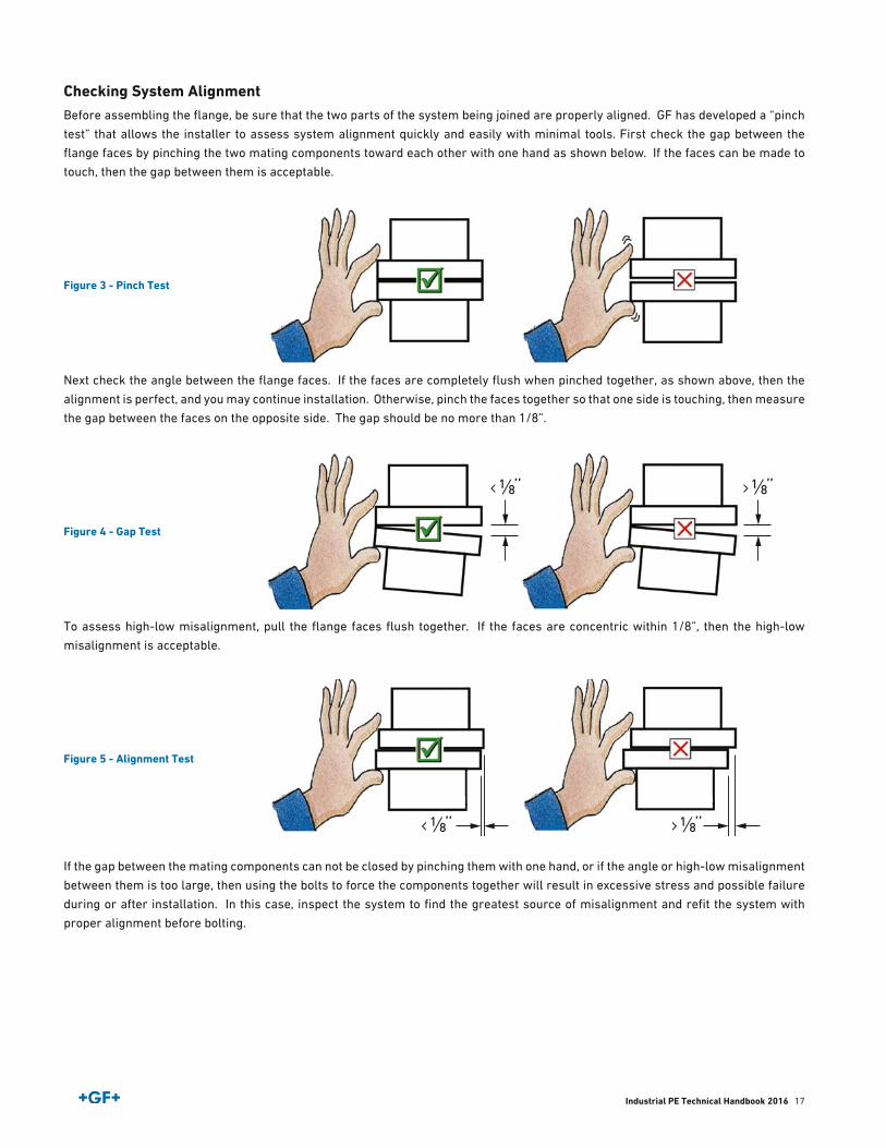
Checking System Alignment Before assembling the flange, be sure that the two parts of the system being joined are properly aligned . GF has developed a “pinch
test” that allows the installer to assess system alignment quickly and easily with minimal tools . First check the gap between the
flange faces by pinching the two mating components toward each other with one hand as shown below . If the faces can be made to
touch, then the gap between them is acceptable .
Figure 3 - Pinch Test
⁄1 8> ”⁄1 8< ”
⁄1 8< ” ⁄1 8> ”
Next check the angle between the flange faces . If the faces are completely flush when pinched together, as shown above, then the
alignment is perfect, and you may continue installation . Otherwise, pinch the faces together so that one side is touching, then measure
the gap between the faces on the opposite side . The gap should be no more than 1/8” .
Figure 4 - Gap Test
⁄1 8> ”⁄1 8< ”
⁄1 8< ” ⁄1 8> ”
To assess high-low misalignment, pull the flange faces flush together . If the faces are concentric within 1/8”, then the high-low
misalignment is acceptable .
Figure 5 - Alignment Test
⁄1 8> ”⁄1 8< ”
⁄1 8< ” ⁄1 8> ”
If the gap between the mating components can not be closed by pinching them with one hand, or if the angle or high-low misalignment
between them is too large, then using the bolts to force the components together will result in excessive stress and possible failure
during or after installation . In this case, inspect the system to find the greatest source of misalignment and refit the system with
proper alignment before bolting .
18 Industrial PE Technical Handbook 2016
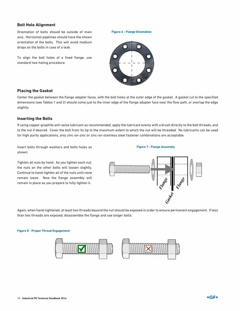
Bolt Hole Alignment
Orientation of bolts should be outside of main
axis . Horizontal pipelines should have the shown
orientation of the bolts . This will avoid medium
drops on the bolts in case of a leak .
To align the bolt holes of a fixed flange, use
standard two-holing procedure .
Figure 6 - Flange Orientation
Placing the Gasket Center the gasket between the flange adapter faces, with the bolt holes at the outer edge of the gasket . A gasket cut to the specified
dimensions (see Tables 1 and 2) should come just to the inner edge of the flange adapter face near the flow path, or overlap the edge
slightly .
Inserting the Bolts If using copper-graphite anti-seize lubricant as recommended, apply the lubricant evenly with a brush directly to the bolt threads, and
to the nut if desired . Cover the bolt from its tip to the maximum extent to which the nut will be threaded . No lubricants can be used
for high purity applications, only zinc-on-zinc or zinc-on-stainless steel fastener combinations are acceptable .
Insert bolts through washers and bolts holes as
shown:
Tighten all nuts by hand . As you tighten each nut,
the nuts on the other bolts will loosen slightly .
Continue to hand-tighten all of the nuts until none
remain loose . Now the flange assembly will
remain in place as you prepare to fully tighten it .
Figure 7 - Flange Assembly
Again, when hand-tightened, at least two threads beyond the nut should be exposed in order to ensure permanent engagement . If less
than two threads are exposed, disassemble the flange and use longer bolts .
Figure 8 - Proper Thread Engagement
19Industrial PE Technical Handbook 2016
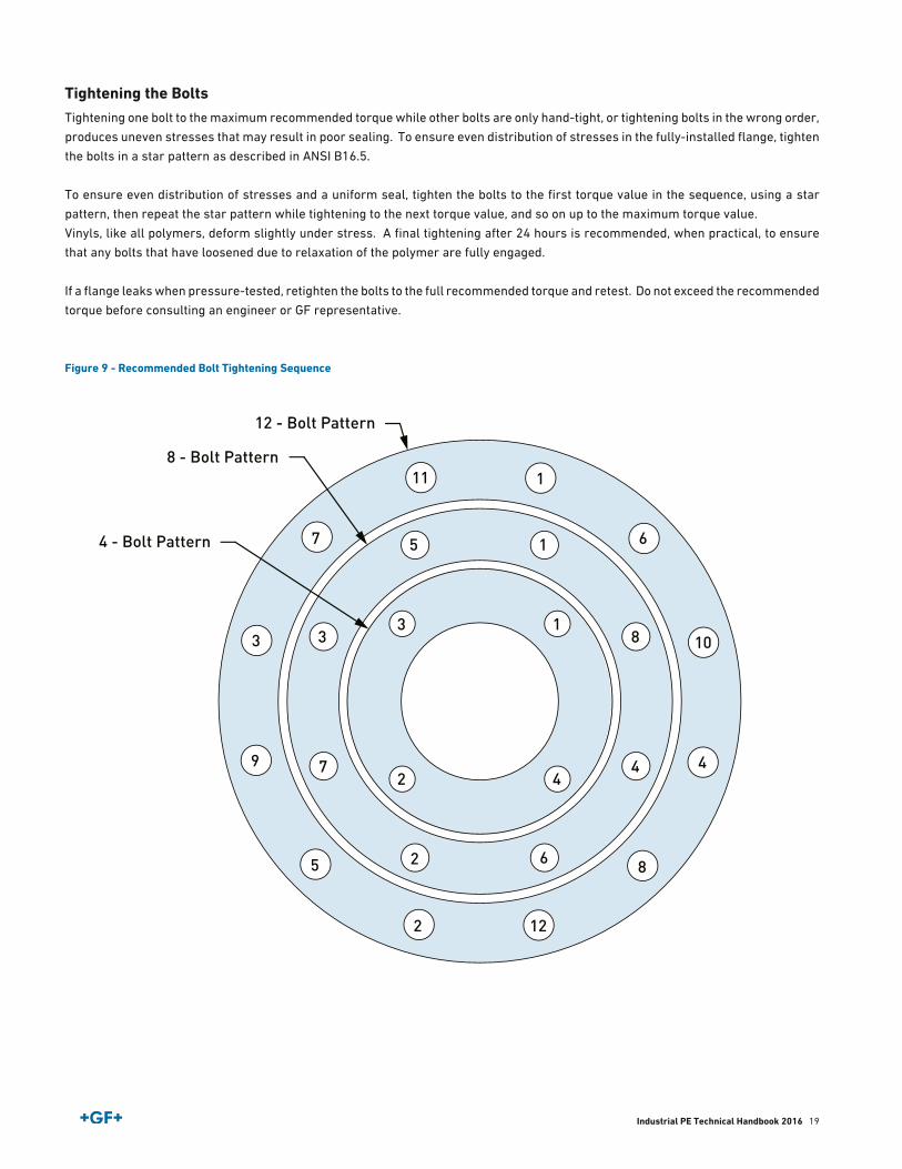
Tightening the Bolts Tightening one bolt to the maximum recommended torque while other bolts are only hand-tight, or tightening bolts in the wrong order,
produces uneven stresses that may result in poor sealing . To ensure even distribution of stresses in the fully-installed flange, tighten
the bolts in a star pattern as described in ANSI B16 .5 .
To ensure even distribution of stresses and a uniform seal, tighten the bolts to the first torque value in the sequence, using a star
pattern, then repeat the star pattern while tightening to the next torque value, and so on up to the maximum torque value .
Vinyls, like all polymers, deform slightly under stress . A final tightening after 24 hours is recommended, when practical, to ensure
that any bolts that have loosened due to relaxation of the polymer are fully engaged .
If a flange leaks when pressure-tested, retighten the bolts to the full recommended torque and retest . Do not exceed the recommended
torque before consulting an engineer or GF representative .
Figure 9 - Recommended Bolt Tightening Sequence
12 - Bolt Pattern
8 - Bolt Pattern
4 - Bolt Pattern
11 1
7 6
3 10
9 4
5
2 12
8
3
5 1
8
4
6
7
2
3 1
2 4
20 Industrial PE Technical Handbook 2016
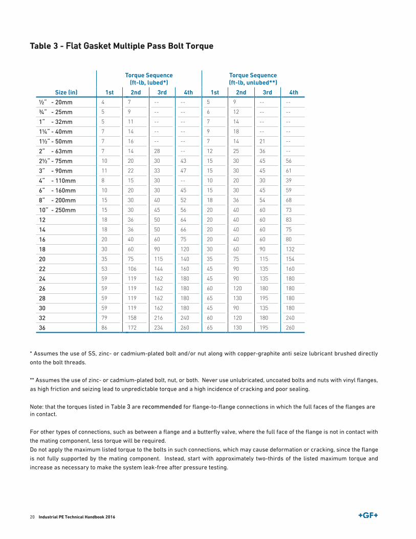
Table 3 - Flat Gasket Multiple Pass Bolt Torque
* Assumes the use of SS, zinc- or cadmium-plated bolt and/or nut along with copper-graphite anti seize lubricant brushed directly onto the bolt threads .
** Assumes the use of zinc- or cadmium-plated bolt, nut, or both . Never use unlubricated, uncoated bolts and nuts with vinyl flanges,
as high friction and seizing lead to unpredictable torque and a high incidence of cracking and poor sealing .
Note: that the torques listed in Table 3 are recommended for flange-to-flange connections in which the full faces of the flanges are in contact .
For other types of connections, such as between a flange and a butterfly valve, where the full face of the flange is not in contact with
the mating component, less torque will be required .
Do not apply the maximum listed torque to the bolts in such connections, which may cause deformation or cracking, since the flange
is not fully supported by the mating component . Instead, start with approximately two-thirds of the listed maximum torque and
increase as necessary to make the system leak-free after pressure testing .
Size (in)
Torque Sequence(ft-lb, lubed*)
Torque Sequence(ft-lb, unlubed**)
1st 2nd 3rd 4th 1st 2nd 3rd 4th
½“ - 20mm 4 7 -- -- 5 9 -- --
¾“ - 25mm 5 9 -- -- 6 12 -- --
1“ - 32mm 5 11 -- -- 7 14 -- --
1¼“ - 40mm 7 14 -- -- 9 18 -- --
1½“ - 50mm 7 16 -- -- 7 14 21 --
2“ - 63mm 7 14 28 -- 12 25 36 --
2½“ - 75mm 10 20 30 43 15 30 45 56
3“ - 90mm 11 22 33 47 15 30 45 61
4“ - 110mm 8 15 30 -- 10 20 30 39
6“ - 160mm 10 20 30 45 15 30 45 59
8“ - 200mm 15 30 40 52 18 36 54 68
10“ - 250mm 15 30 45 56 20 40 60 73
12 18 36 50 64 20 40 60 83
14 18 36 50 66 20 40 60 75
16 20 40 60 75 20 40 60 80
18 30 60 90 120 30 60 90 132
20 35 75 115 140 35 75 115 154
22 53 106 144 160 45 90 135 160
24 59 119 162 180 45 90 135 180
26 59 119 162 180 60 120 180 180
28 59 119 162 180 65 130 195 180
30 59 119 162 180 45 90 135 180
32 79 158 216 240 60 120 180 240
36 86 172 234 260 65 130 195 260
21Industrial PE Technical Handbook 2016
Documentation for Flanged Connections Keep Instructions Available Provide a copy of these instructions to every installer on the job site prior to beginning installation . Installers who have worked pri-
marily with metal flanges often make critical mistakes when installing vinyl flanges . Even experienced vinyl installers will benefit
from a quick review of good installation practices before starting a new job .
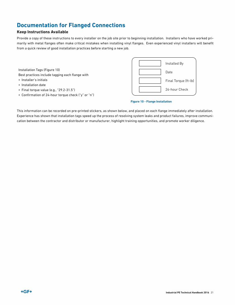
Installation Tags (Figure 10)
Best practices include tagging each flange with
• Installer’s initials
• Installation date
• Final torque value (e .g ., “29 .2-31 .5”)
• Confirmation of 24-hour torque check (“y” or “n”)
Installed By
Date
Final Torque (ft-lb)
24-hour Check
Installed By
Date
Figure 10 - Flange Installation
This information can be recorded on pre-printed stickers, as shown below, and placed on each flange immediately after installation .
Experience has shown that installation tags speed up the process of resolving system leaks and product failures, improve communi-
cation between the contractor and distributor or manufacturer, highlight training opportunities, and promote worker diligence .
22 Industrial PE Technical Handbook 2016
Creating Union JointsIntroduction Because unions and ball valves have similar, threaded nut connectors, these instructions have been written with both of these
components in mind . GF unions and ball valves are designed to provide many years of service when installed properly .
As with any piping system component, unions and valves have particular considerations that must be kept in mind during installation
in order to ensure best performance . Even experienced installers will benefit from reviewing these instructions before each
installation .
Valve Support Ball valves must be well-supported . Refer to the GF Engineering Handbook for detailed instructions on support installation .
(www .gfpiping .com) An unsupported or insufficiently-supported valve body will twist when opened and closed, subjecting the union
connection to torque stress that may cause cracking or distortion and subsequent leakage .
System Alignment The major contributor to union nut failures is misalignment . Uneven compression of the o-ring will cause leaks to occur . Union nuts
can be damaged by the stress of holding a misaligned system together .
Sealing Mechanism GF union connections use an o-ring as the sealing mechanism which is highly effective under relatively low tightening force .
Dirt and Debris An often overlooked issue is the presence of dirt and debris on the o-ring or sealing surface . This will prevent proper o-ring sealing;
if it is present on the nut or body threads, it will clog the threads and prevent proper tightening .
Installation Understand and carefully follow these installation steps in order to ensure a seal that is sufficient to guard against leaks while
avoiding excessive forces that can damage the union nut .
End Connectors Always remove the union nut and end connectors from the ball valve for installation . Make sure that you slide the union nut onto the
pipe, with the threads facing the proper direction, BEFORE installing the end connector .
Solvent Cementing Solvent cementing of pipe into the union or ball valve sockets should be done before the union nut connections are engaged . Be
careful not to get any cement on the sealing surfaces, which can disrupt the seal and cause leaks . For best results, allow the
cemented joint to properly cure prior to assembling the union nut connection, in order to avoid damaging the uncured joint .
O-Ring Placement Once the cement has cured, ensure that the o-ring is securely seated in its groove . The o-ring should rest securely in place without
adhesive or other aids .
• Never use any foreign substance or object to hold the o-ring in place .
Union Connection There should be no gap between the mating components, so that the threaded nut serves only to compress the o-ring, thus creating
the seal . However, a small gap (less than 1/8”) between the mating components is acceptable .
• Never use the union nuts to draw together any gaps between the mating faces of the components or to correct any system misalignment .
23Industrial PE Technical Handbook 2016
Hand-Tightening (all sizes) (see Table 4) The next step is to hand-tighten the union nut . With the o-ring in place, engage the nut with its mating threads and turn clockwise with
one hand . Continue turning with moderate force until the nut no longer turns .
Be careful to use reasonable force when tightening the nut . Your grip should be firm but not aggressive . The nut should turn easily
until it bottoms out and brings the mating faces into direct contact .
It is recommended that you place an indexing mark with a permanent marker on the union nut and body to identify the hand tight
position .
Do not use any form of lubricant on the threads of the union nut .
Union and ball valve sizes ½” through 1½” should be sufficiently sealed after hand-tightening, for the hydrostatic pressure test of the
system .
Optional: Further Tightening (2”)Based on experience, or system requirements, the installer may choose to turn the nut an additional 1/8 turn (approximately 45°) in
order to ensure a better seal before hydrostatically pressure testing the system . To do this, use a strap wrench to turn the nut 1/8
turn past the index mark applied after assembly .
Do not exceed 1/8 turn past the index mark .
Do not use any metallic tools . (Tool marks on the union nut will void manufacturer’s warranty .)
At this point, the system should be hydrostatically pressure tested before turning the union nut any farther .
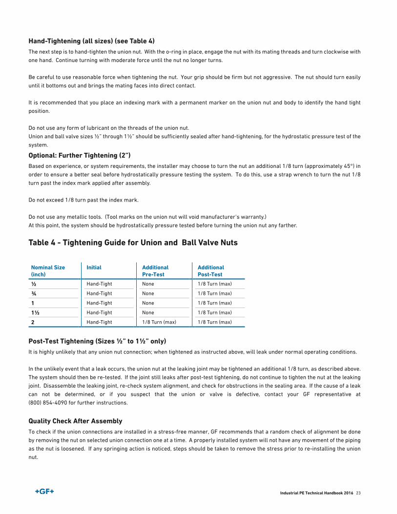
Table 4 - Tightening Guide for Union and Ball Valve Nuts
Nominal Size(inch)
Initial AdditionalPre-Test
AdditionalPost-Test
½ Hand-Tight None 1/8 Turn (max)
¾ Hand-Tight None 1/8 Turn (max)
1 Hand-Tight None 1/8 Turn (max)
1½ Hand-Tight None 1/8 Turn (max)
2 Hand-Tight 1/8 Turn (max) 1/8 Turn (max)
Post-Test Tightening (Sizes ½” to 1½” only)It is highly unlikely that any union nut connection; when tightened as instructed above, will leak under normal operating conditions .
In the unlikely event that a leak occurs, the union nut at the leaking joint may be tightened an additional 1/8 turn, as described above .
The system should then be re-tested . If the joint still leaks after post-test tightening, do not continue to tighten the nut at the leaking
joint . Disassemble the leaking joint, re-check system alignment, and check for obstructions in the sealing area . If the cause of a leak
can not be determined, or if you suspect that the union or valve is defective, contact your GF representative at
(800) 854-4090 for further instructions .
Quality Check After Assembly To check if the union connections are installed in a stress-free manner, GF recommends that a random check of alignment be done
by removing the nut on selected union connection one at a time . A properly installed system will not have any movement of the piping
as the nut is loosened . If any springing action is noticed, steps should be taken to remove the stress prior to re-installing the union
nut .
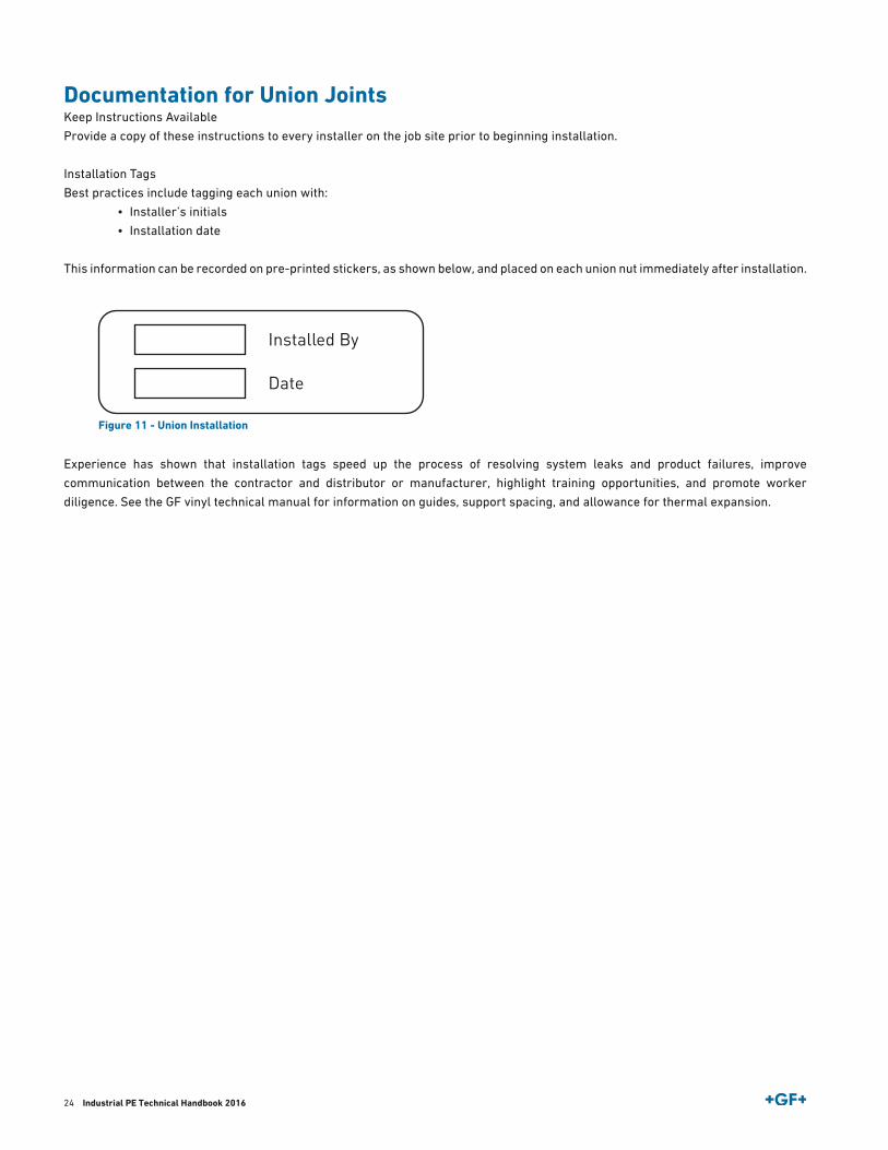
24 Industrial PE Technical Handbook 2016
Documentation for Union Joints Keep Instructions Available
Provide a copy of these instructions to every installer on the job site prior to beginning installation .
Installation Tags
Best practices include tagging each union with:
• Installer’s initials
• Installation date
This information can be recorded on pre-printed stickers, as shown below, and placed on each union nut immediately after installation .
Figure 11 - Union Installation
Installed By
Date
Final Torque (ft-lb)
24-hour Check
Installed By
Date
Experience has shown that installation tags speed up the process of resolving system leaks and product failures, improve
communication between the contractor and distributor or manufacturer, highlight training opportunities, and promote worker
diligence . See the GF vinyl technical manual for information on guides, support spacing, and allowance for thermal expansion .
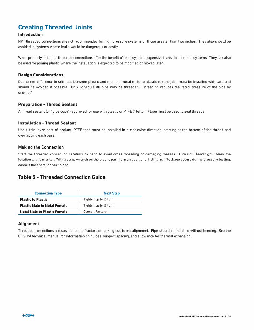
25Industrial PE Technical Handbook 2016
Creating Threaded JointsIntroduction NPT threaded connections are not recommended for high pressure systems or those greater than two inches . They also should be
avoided in systems where leaks would be dangerous or costly .
When properly installed, threaded connections offer the benefit of an easy and inexpensive transition to metal systems . They can also
be used for joining plastic where the installation is expected to be modified or moved later .
Design Considerations Due to the difference in stiffness between plastic and metal, a metal male-to-plastic female joint must be installed with care and
should be avoided if possible . Only Schedule 80 pipe may be threaded . Threading reduces the rated pressure of the pipe by
one-half .
Preparation - Thread Sealant A thread sealant (or “pipe dope”) approved for use with plastic or PTFE (“Teflon®”) tape must be used to seal threads .
Installation - Thread Sealant Use a thin, even coat of sealant . PTFE tape must be installed in a clockwise direction, starting at the bottom of the thread and
overlapping each pass .
Making the Connection Start the threaded connection carefully by hand to avoid cross threading or damaging threads . Turn until hand tight . Mark the
location with a marker . With a strap wrench on the plastic part, turn an additional half turn . If leakage occurs during pressure testing,
consult the chart for next steps .
Table 5 - Threaded Connection Guide
Connection Type Next Step
Plastic to Plastic Tighten up to ½ turn
Plastic Male to Metal Female Tighten up to ½ turn
Metal Male to Plastic Female Consult Factory
Alignment Threaded connections are susceptible to fracture or leaking due to misalignment . Pipe should be installed without bending . See the
GF vinyl technical manual for information on guides, support spacing, and allowance for thermal expansion .
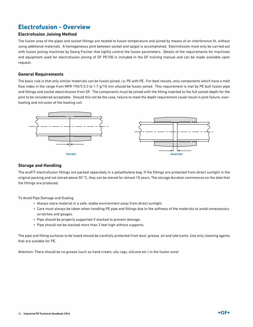
26 Industrial PE Technical Handbook 2016
Electrofusion - OverviewElectrofusion Joining MethodThe fusion area of the pipes and socket fittings are heated to fusion temperature and joined by means of an interference fit, without
using additional materials . A homogeneous joint between socket and spigot is accomplished . Electrofusion must only be carried out
with fusion joining machines by Georg Fischer that tightly control the fusion parameters . Details of the requirements for machines
and equipment used for electrofusion joining of GF PE100 is included in the GF training manual and can be made available upon
request .
General RequirementsThe basic rule is that only similar materials can be fusion joined, i .e . PE with PE . For best results, only components which have a melt
flow index in the range from MFR 190/5 0 .3 to 1 .7 g/10 min should be fusion joined . This requirement is met by PE butt fusion pipe
and fittings and socket electrofusion from GF . The components must be joined with the fitting inserted to the full socket depth for the
joint to be considered acceptable . Should this not be the case, failure to meet the depth requirement could result in joint failure, over-
heating and intrusion of the heating coil .
Correct Incorrect
Storage and HandlingThe ecoFIT electrofusion fittings are packed separately in a polyethylene bag . If the fittings are protected from direct sunlight in the
original packing and not stored above 50 °C, they can be stored for almost 10 years . The storage duration commences on the date that
the fittings are produced .
To Avoid Pipe Damage and Ovaling
• Always store material in a safe, stable environment away from direct sunlight .
• Care must always be taken when handling PE pipe and fittings due to the softness of the materials to avoid unnecessary
scratches and gouges .
• Pipe should be properly supported if stacked to prevent damage .
• Pipe should not be stacked more than 3 feet high without supports .
The pipe and fitting surfaces to be fused should be carefully protected from dust, grease, oil and lubricants . Use only cleaning agents
that are suitable for PE .
Attention: There should be no grease (such as hand cream, oily rags, silicone etc .) in the fusion zone!
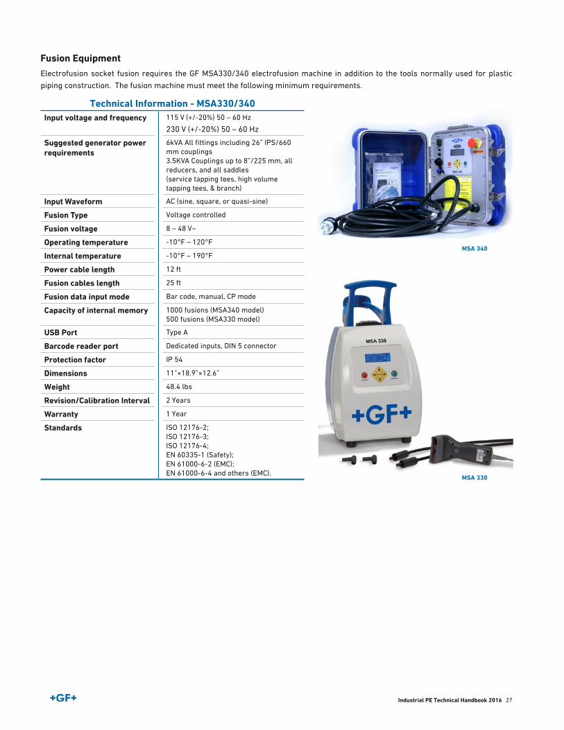
27Industrial PE Technical Handbook 2016
Fusion EquipmentElectrofusion socket fusion requires the GF MSA330/340 electrofusion machine in addition to the tools normally used for plastic
piping construction . The fusion machine must meet the following minimum requirements .
Technical Information - MSA330/340Input voltage and frequency 115 V (+/-20%) 50 – 60 Hz
230 V (+/-20%) 50 – 60 Hz
Suggested generator power requirements
6kVA All fittings including 26” IPS/660 mm couplings 3 .5KVA Couplings up to 8”/225 mm, all reducers, and all saddles (service tapping tees, high volume tapping tees, & branch)
Input Waveform AC (sine, square, or quasi-sine)
Fusion Type Voltage controlled
Fusion voltage 8 – 48 V~
Operating temperature -10°F – 120°F
Internal temperature -10°F – 190°F
Power cable length 12 ft
Fusion cables length 25 ft
Fusion data input mode Bar code, manual, CP mode
Capacity of internal memory 1000 fusions (MSA340 model) 500 fusions (MSA330 model)
USB Port Type A
Barcode reader port Dedicated inputs, DIN 5 connector
Protection factor IP 54
Dimensions 11”×18 .9”×12 .6”
Weight 48 .4 lbs
Revision/Calibration Interval 2 Years
Warranty 1 Year
Standards ISO 12176-2; ISO 12176-3; ISO 12176-4; EN 60335-1 (Safety); EN 61000-6-2 (EMC); EN 61000-6-4 and others (EMC) .
MSA 340
MSA 330
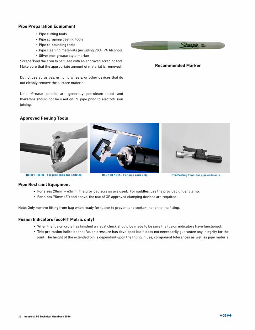
28 Industrial PE Technical Handbook 2016
Pipe Preparation Equipment
• Pipe cutting tools
• Pipe scraping/peeling tools
• Pipe re-rounding tools
• Pipe cleaning materials (including 90% IPA Alcohol)
• Silver non-grease style marker
Scrape/Peel the area to be fused with an approved scraping tool .
Make sure that the appropriate amount of material is removed .
Do not use abrasives, grinding wheels, or other devices that do
not cleanly remove the surface material .
Note: Grease pencils are generally petroleum-based and
therefore should not be used on PE pipe prior to electrofusion
joining .
Recommended Marker
Approved Peeling Tools
Rotary Peeler - For pipe ends and saddles RTC 160 / 315 - For pipe ends only PT4 Peeling Tool - for pipe ends only
Pipe Restraint Equipment • For sizes 20mm – 63mm, the provided screws are used . For saddles, use the provided under clamp .
• For sizes 75mm (2”) and above, the use of GF approved clamping devices are required .
Note: Only remove fitting from bag when ready for fusion to prevent and contamination to the fitting .
Fusion Indicators (ecoFIT Metric only) • When the fusion cycle has finished a visual check should be made to be sure the fusion indicators have functioned .
• This protrusion indicates that fusion pressure has developed but it does not necessarily guarantee any integrity for the
joint . The height of the extended pin is dependant upon the fitting in use, component tolerances as well as pipe material .
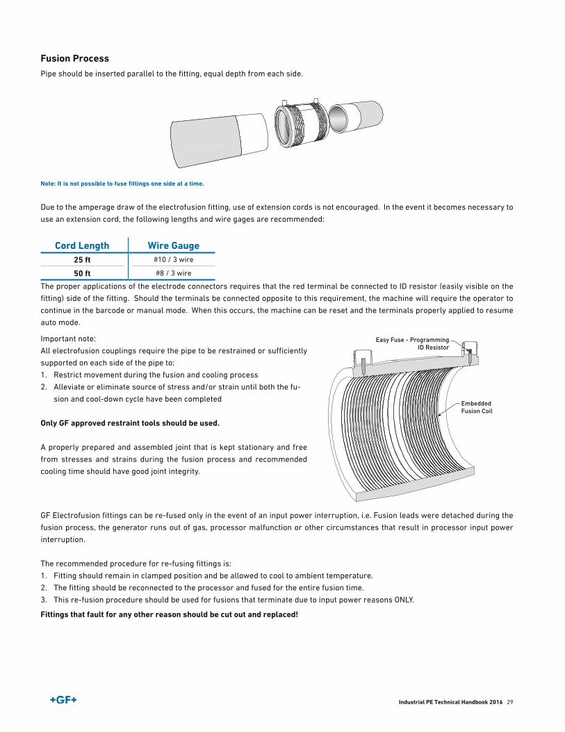
29Industrial PE Technical Handbook 2016
Fusion Process Pipe should be inserted parallel to the fitting, equal depth from each side .
Note: It is not possible to fuse fittings one side at a time.
Due to the amperage draw of the electrofusion fitting, use of extension cords is not encouraged . In the event it becomes necessary to
use an extension cord, the following lengths and wire gages are recommended:
Cord Length Wire Gauge25 ft #10 / 3 wire
50 ft #8 / 3 wire
The proper applications of the electrode connectors requires that the red terminal be connected to ID resistor (easily visible on the
fitting) side of the fitting . Should the terminals be connected opposite to this requirement, the machine will require the operator to
continue in the barcode or manual mode . When this occurs, the machine can be reset and the terminals properly applied to resume
auto mode .
Important note:
All electrofusion couplings require the pipe to be restrained or sufficiently
supported on each side of the pipe to:
1 . Restrict movement during the fusion and cooling process
2 . Alleviate or eliminate source of stress and/or strain until both the fu-
sion and cool-down cycle have been completed
Only GF approved restraint tools should be used.
A properly prepared and assembled joint that is kept stationary and free
from stresses and strains during the fusion process and recommended
cooling time should have good joint integrity .
Easy Fuse - ProgrammingID Resistor
EmbeddedFusion Coil
GF Electrofusion fittings can be re-fused only in the event of an input power interruption, i .e . Fusion leads were detached during the
fusion process, the generator runs out of gas, processor malfunction or other circumstances that result in processor input power
interruption .
The recommended procedure for re-fusing fittings is:
1 . Fitting should remain in clamped position and be allowed to cool to ambient temperature .
2 . The fitting should be reconnected to the processor and fused for the entire fusion time .
3 . This re-fusion procedure should be used for fusions that terminate due to input power reasons ONLY .
Fittings that fault for any other reason should be cut out and replaced!
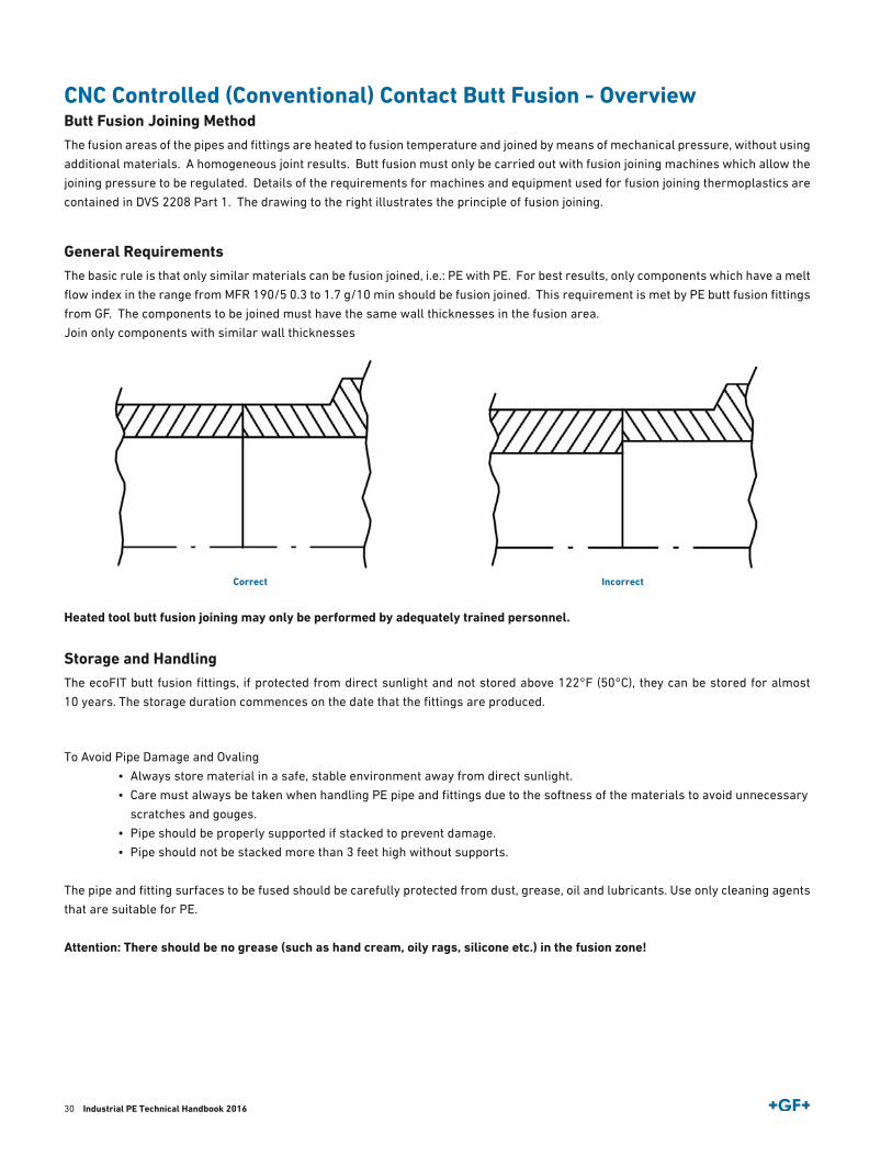
30 Industrial PE Technical Handbook 2016
CNC Controlled (Conventional) Contact Butt Fusion - OverviewButt Fusion Joining MethodThe fusion areas of the pipes and fittings are heated to fusion temperature and joined by means of mechanical pressure, without using
additional materials . A homogeneous joint results . Butt fusion must only be carried out with fusion joining machines which allow the
joining pressure to be regulated . Details of the requirements for machines and equipment used for fusion joining thermoplastics are
contained in DVS 2208 Part 1 . The drawing to the right illustrates the principle of fusion joining .
General RequirementsThe basic rule is that only similar materials can be fusion joined, i .e .: PE with PE . For best results, only components which have a melt
flow index in the range from MFR 190/5 0 .3 to 1 .7 g/10 min should be fusion joined . This requirement is met by PE butt fusion fittings
from GF . The components to be joined must have the same wall thicknesses in the fusion area .
Join only components with similar wall thicknesses
Correct Incorrect
Heated tool butt fusion joining may only be performed by adequately trained personnel.
Storage and HandlingThe ecoFIT butt fusion fittings, if protected from direct sunlight and not stored above 122°F (50°C), they can be stored for almost
10 years . The storage duration commences on the date that the fittings are produced .
To Avoid Pipe Damage and Ovaling
• Always store material in a safe, stable environment away from direct sunlight .
• Care must always be taken when handling PE pipe and fittings due to the softness of the materials to avoid unnecessary
scratches and gouges .
• Pipe should be properly supported if stacked to prevent damage .
• Pipe should not be stacked more than 3 feet high without supports .
The pipe and fitting surfaces to be fused should be carefully protected from dust, grease, oil and lubricants . Use only cleaning agents
that are suitable for PE .
Attention: There should be no grease (such as hand cream, oily rags, silicone etc.) in the fusion zone!
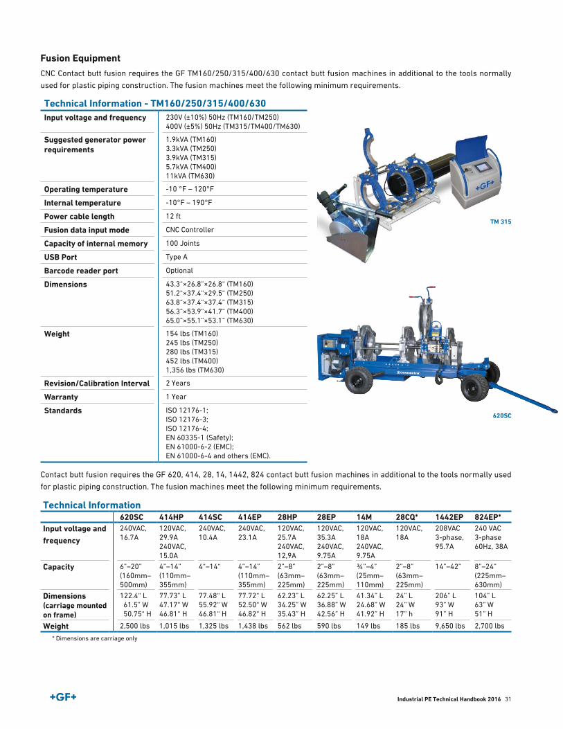
31Industrial PE Technical Handbook 2016
Fusion EquipmentCNC Contact butt fusion requires the GF TM160/250/315/400/630 contact butt fusion machines in additional to the tools normally
used for plastic piping construction . The fusion machines meet the following minimum requirements .
Technical Information - TM160/250/315/400/630Input voltage and frequency 230V (±10%) 50Hz (TM160/TM250)
400V (±5%) 50Hz (TM315/TM400/TM630)
Suggested generator power requirements
1 .9kVA (TM160)3 .3kVA (TM250)3 .9kVA (TM315)5 .7kVA (TM400)11kVA (TM630)
Operating temperature -10 °F – 120°F
Internal temperature -10°F – 190°F
Power cable length 12 ft
Fusion data input mode CNC Controller
Capacity of internal memory 100 Joints
USB Port Type A
Barcode reader port Optional
Dimensions 43 .3“×26 .8”×26 .8“ (TM160)51 .2“×37 .4“×29 .5“ (TM250)63 .8“×37 .4“×37 .4“ (TM315)56 .3“×53 .9“×41 .7“ (TM400)65 .0“×55 .1“×53 .1“ (TM630)
Weight 154 lbs (TM160)245 lbs (TM250)280 lbs (TM315)452 lbs (TM400)1,356 lbs (TM630)
Revision/Calibration Interval 2 Years
Warranty 1 Year
Standards ISO 12176-1;ISO 12176-3; ISO 12176-4; EN 60335-1 (Safety); EN 61000-6-2 (EMC); EN 61000-6-4 and others (EMC) .
Contact butt fusion requires the GF 620, 414, 28, 14, 1442, 824 contact butt fusion machines in additional to the tools normally used
for plastic piping construction . The fusion machines meet the following minimum requirements .
Technical Information620SC 414HP 414SC 414EP 28HP 28EP 14M 28CQ* 1442EP 824EP*
Input voltage and frequency
240VAC, 16 .7A
120VAC, 29 .9A240VAC, 15 .0A
240VAC, 10 .4A
240VAC, 23 .1A
120VAC, 25 .7A240VAC, 12,9A
120VAC, 35 .3A240VAC, 9 .75A
120VAC, 18A240VAC, 9 .75A
120VAC, 18A
208VAC 3-phase, 95 .7A
240 VAC 3-phase 60Hz, 38A
Capacity 6”–20” (160mm–500mm)
4”–14” (110mm–355mm)
4“–14“ 4”–14” (110mm–355mm)
2”–8” (63mm–225mm)
2”–8” (63mm–225mm)
¾”–4” (25mm–110mm)
2”–8” (63mm–225mm)
14”–42” 8”–24” (225mm–630mm)
Dimensions (carriage mounted on frame)
122 .4“ L 61 .5” W 50 .75“ H
77 .73” L47 .17“ W46 .81“ H
77 .48“ L55 .92“ W46 .81“ H
77 .72“ L52 .50“ W46 .82“ H
62 .23” L34 .25” W35 .43” H
62 .25” L36 .88” W42 .56” H
41 .34” L24 .68” W41 .92” H
24” L24” W17” h
206” L93” W91” H
104” L63” W51” H
Weight 2,500 lbs 1,015 lbs 1,325 lbs 1,438 lbs 562 lbs 590 lbs 149 lbs 185 lbs 9,650 lbs 2,700 lbs
* Dimensions are carriage only
TM 315
620SC
32 Industrial PE Technical Handbook 2016
Pipe Preparation EquipmentButt fusion joining requires a special joining machine in addition to the tools normally used for plastic piping construction (pipe
cutters, saw with cutting guide) . The fusion joining machine must meet the following minimum requirements:
The clamping equipment must hold the various parts securely without damaging the surfaces . Possible ovality can be largely
compensated by centered clamping of the components to be joined . It must also be possible to hold all parts firmly in alignment .
The machine must also be capable of face planing the fusion surfaces of pipes and fittings .
The fusion joining machine must be sufficiently solid to be able to absorb the pressures arising during the fusion procedure without
detrimentally deforming the joint .
The heating surfaces of the heating element must be flat and parallel . The temperature variation over the working area must not
exceed 50°F (10°C) . The machine should be set up and operated according to the manufacturer’s instructions .
The fusion procedure detailed below including the preparation is based on DVS 2207-1 Welding of thermoplastics - Heated tool
welding of pipes, pipeline, components and sheets made from PE .
Note:
Protect the area of the fusion joint from adverse weather conditions, such as rain, snow and wind . At temperatures below 41°F (5°C)
or above 113°F (45°C), measures must be taken to ensure that the temperature in the working area is in the range required for
satisfactory joining and does not hinder the necessary manual tasks .
IR Plus® Infrared Non-contact Butt FusionFor further information please contact your local GF Distributor.

33Industrial PE Technical Handbook 2016
System Specification - Design Flow™ Piping Systems in IPS/DIPS Polyethylene (PE)
1.0 ScopeThis specification covers the requirements for the GF Piping Systems (PE) IPS/DIPS Piping Systems intended for a wide range of
industrial applications including water, wastewater and effluent treatment as well as a wide range of chemical applications . The
components of the ecoFIT IPS (PE) piping system are in accordance with the following standards .
2.0 Basic System Data
2.1 Material Specification for Design Flow (PE) IPS/DIPS Pipe & FittingsA . All Design Flow (PE) IPS/DIPS pipe shall be manufactured from a PE100/4710 high density copolymer resin meeting the
requirements of ASTM D3350 and D3035 . Pipe shall be manufactured to SDR 11 or SDR 17 dimensions with a pressure
rating of 200 psi or 130 psi respectively when measured at 68°F . The material shall achieve a minimum tensile strength
of 3600 psi when tested at 73°F according to ASTM D 638 . The material shall also comply with guidelines approved by the
U .S . Food and Drug Administration (FDA) as specified in the Code of Federal Regulations (CFR), Title 21, Section 177 .160
for basic polyethylene and Section 178 .3297 “colorants for polymers” for pigments suitable for contact with foodstuff,
pharmaceutical use and potable water . Piping materials shall conform to the requirements of ASTM D2837 for hydrostatic
design basis . Industrial grade pipe shall be supplied capped off at the extruder and supplied in 20ft lengths .
B . All Design Flow (PE) IPS/DIPS fittings shall be manufactured from a PE100/4710 high density copolymer resin meeting
the requirements of ASTM D3350 . Fittings in sizes through 42” shall be butt fusion type, suitable for heat fusion joining .
All fittings through 42” shall be compatible with manual and contact butt fusion machines . Fittings shall be manufactured
to SDR 11 or SDR 17 dimensions with a pressure rating of 200 psi or 130 psi respectively when measured at 68°F . All
flanges shall be manufactured to SDR 11 dimensions with a pressure rating of 150 psi when measured at 68°F .
C . All components of the pipe and fitting system shall conform to the following applicable ASTM Standards, D3035, D638,
D2837, shall conform to NSF Standard 61 for potable water applications and shall conform to FDA CFR 21 177 .160 and
178 .3297 . All pipes shall be marked with manufacturers name, pipe size, SDR rating, type, quality control mark and
pressure rating information . Fittings shall be embossed with a permanent identification during the production process to
ensure traceability . All flanged connections shall utilize flange rings with bolt patterns to accommodate ANSI bolt circles .
All threaded connections shall have pipe threads designed in accordance with the requirements of ASTM D2464, which
references ANSI B1 .20 .1 (formerly B2 .1) for tapered pipe threads (NPT) .
D . Pipe, valves, fittings and joining equipment shall be supplied by a single source provider to insure compatibility of system
components and to assure proper joint integrity .
E . Acceptable material shall be GF Design Flow Industrial Polyethylene as manufactured by Georg Fischer Central Plastics .
F . Pipe and fittings shall be manufactured by an FM approved and listed facility .
Section 2: IPS
34 Industrial PE Technical Handbook 2016
3.0 Material Specification for Valves
3.1 Butterfly Valves
3.1.1 Plastic Butterfly Valves
A . Butterfly valves suitable for the Design Flow (PE) System of GF Piping Systems are made from PP-H, ABS, or PVC material .
B . All butterfly valves, sizes 2”–12”, shall be GF Piping Systems Type 567/578 wafer/lug type with a double eccentric disc
design manufactured by GF Piping Systems in accordance with EN ISO 16136 . Seals shall be available in EPDM, FPM
and PTFE/FPM . The lever handle shall be lockable in increments of 5 degrees . There shall always be six teeth engaged
between the ratchet and the index plate to ensure accurate and safe positioning of the lever . There shall be the option of
fine adjustment by use of a specific hand lever, allowing the disc to be exposed at any angle between 0° and 90° . As an
option, the hand lever shall be lockable . The hand lever shall be manufactured of high strength PPGF (polypropylene glass
fiber reinforced) . The option of an integrated electric position indicator shall be available . As an option the valves can be
actuated by gear box with hand wheel . The electric position indicator shall be integrated into the mounting flange . But-
terfly valves shall have low actuation torque to enable easy operation . All butterfly valves Type 567/578 manufactured
by GF Piping Systems are designed for a nominal pressure rate of 10 bar . All butterfly valves Type 563 are designed for a
nominal pressure rate of 4 bar .
3.1.1.1 Electrically Actuated Butterfly Valves
A . Electric actuators shall be GF Piping Systems Types EA31 or EA42 dependent on valve size . They shall be manufactured by
GF Piping Systems in accordance with EN 61010-1, as per the above specifications . Actuator housing shall be made of PPGF
(polypropylene glass fiber reinforced), flame retardant and feature external stainless steel screws . All electric actuators shall
have an integrated emergency manual override and integrated optical position indication .
B . All electric actuator types shall have the following accessories available:
• Fail-safe unit
• Heating element
• Cycle extension, monitoring, and counting
• Motor current monitoring
• Position signalization
• Positioner Type PE25
• Limit switch kits Ag-Ni, Au, NPN, PNP
• Manual override
• AS-Interface Plug Module
3.1.1.2 Pneumatically Actuated Butterfly Valves
A . Pneumatic actuators shall be GF Piping Systems Types PA 35 (sizes 2” and 2½”), PA40 (size 3” only), PA45 (size 4”), PA55
(size 6”), PA60, PA65 . They shall be supplied by GF Piping Systems . Pneumatic actuators shall be available as fail safe
close, fail safe open and double acting and have an integrated optical position indication . Actuator housing shall be made of
hardened anodized aluminum . Actuators shall contain integrated Namur interfaces for the easy mounting of positioners,
limit switches and accessories . All pneumatically actuated butterfly valves shall have the following accessories available:
• Solenoid pilot valve remote or direct mounted in voltages 24VDC/AC, 110VAC, 230VAC
• Positioner Type DSR 500-3
• Feedback with following limit switches Ag-Ni, Au, NPN, PNP, NAMUR
• Stroke limiter & emergency manual override
• ASI-controller
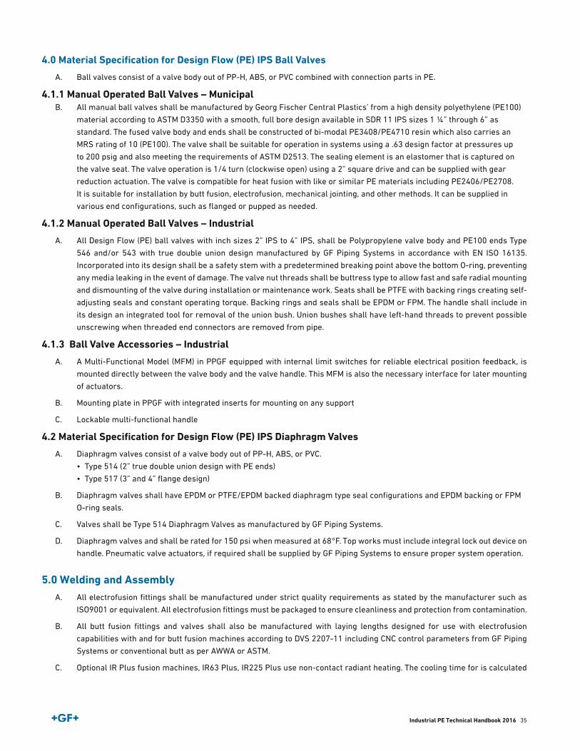
35Industrial PE Technical Handbook 2016
4.0 Material Specification for Design Flow (PE) IPS Ball Valves
A . Ball valves consist of a valve body out of PP-H, ABS, or PVC combined with connection parts in PE .
4.1.1 Manual Operated Ball Valves – MunicipalB . All manual ball valves shall be manufactured by Georg Fischer Central Plastics’ from a high density polyethylene (PE100)
material according to ASTM D3350 with a smooth, full bore design available in SDR 11 IPS sizes 1 ¼” through 6” as
standard . The fused valve body and ends shall be constructed of bi-modal PE3408/PE4710 resin which also carries an
MRS rating of 10 (PE100) . The valve shall be suitable for operation in systems using a .63 design factor at pressures up
to 200 psig and also meeting the requirements of ASTM D2513 . The sealing element is an elastomer that is captured on
the valve seat . The valve operation is 1/4 turn (clockwise open) using a 2” square drive and can be supplied with gear
reduction actuation . The valve is compatible for heat fusion with like or similar PE materials including PE2406/PE2708 .
It is suitable for installation by butt fusion, electrofusion, mechanical jointing, and other methods . It can be supplied in
various end configurations, such as flanged or pupped as needed .
4.1.2 Manual Operated Ball Valves – Industrial
A . All Design Flow (PE) ball valves with inch sizes 2” IPS to 4” IPS, shall be Polypropylene valve body and PE100 ends Type
546 and/or 543 with true double union design manufactured by GF Piping Systems in accordance with EN ISO 16135 .
Incorporated into its design shall be a safety stem with a predetermined breaking point above the bottom O-ring, preventing
any media leaking in the event of damage . The valve nut threads shall be buttress type to allow fast and safe radial mounting
and dismounting of the valve during installation or maintenance work . Seats shall be PTFE with backing rings creating self-
adjusting seals and constant operating torque . Backing rings and seals shall be EPDM or FPM . The handle shall include in
its design an integrated tool for removal of the union bush . Union bushes shall have left-hand threads to prevent possible
unscrewing when threaded end connectors are removed from pipe .
4.1.3 Ball Valve Accessories – Industrial
A . A Multi-Functional Model (MFM) in PPGF equipped with internal limit switches for reliable electrical position feedback, is
mounted directly between the valve body and the valve handle . This MFM is also the necessary interface for later mounting
of actuators .
B . Mounting plate in PPGF with integrated inserts for mounting on any support
C . Lockable multi-functional handle
4.2 Material Specification for Design Flow (PE) IPS Diaphragm Valves
A . Diaphragm valves consist of a valve body out of PP-H, ABS, or PVC .
• Type 514 (2” true double union design with PE ends)
• Type 517 (3” and 4” flange design)
B . Diaphragm valves shall have EPDM or PTFE/EPDM backed diaphragm type seal configurations and EPDM backing or FPM
O-ring seals .
C . Valves shall be Type 514 Diaphragm Valves as manufactured by GF Piping Systems .
D . Diaphragm valves and shall be rated for 150 psi when measured at 68°F . Top works must include integral lock out device on
handle . Pneumatic valve actuators, if required shall be supplied by GF Piping Systems to ensure proper system operation .
5.0 Welding and Assembly
A . All electrofusion fittings shall be manufactured under strict quality requirements as stated by the manufacturer such as
ISO9001 or equivalent . All electrofusion fittings must be packaged to ensure cleanliness and protection from contamination .
B . All butt fusion fittings and valves shall also be manufactured with laying lengths designed for use with electrofusion
capabilities with and for butt fusion machines according to DVS 2207-11 including CNC control parameters from GF Piping
Systems or conventional butt as per AWWA or ASTM .
C . Optional IR Plus fusion machines, IR63 Plus, IR225 Plus use non-contact radiant heating . The cooling time for is calculated
36 Industrial PE Technical Handbook 2016
on the basis of ambient temperature and the bead surface temperature . To increase the cooling capacity, an additional
cooling fan is included in the IR-225 Plus .
D . Only authorized and certified welders by GF Piping Systems are allowed to perform fusion on GF approved equipment .
E . The welding and the installation should be in accordance with GF Piping Systems guidelines .
6.0 Quality
6.1 Production Conditions Pipes, fittings, valves and accessories shall be manufactured in an environment equivalent to, or meeting the requirements of a
Quality Assurance System such as ISO 9001 .
6.2 UniformityPipes, fittings, valves and welding machines shall be supplied from one manufacturer, GF Piping Systems to ensure correct and
proper jointing between components and uniform chemical and physical properties of the piping system .
6.3 Handling of MaterialA . Material shall be stored in original packaging and protected from environmental damage until installation .
B . Pipe shall be supported sufficiently to prevent sagging . Care shall be taken not to gouge or otherwise notch the pipe in
excess of 10% of the wall thickness .
6.4 Training, Certification and Installation A . Site personnel, permissible for PE piping installation, shall undergo training and certification according to manufacturer’s
published guidelines prior to performing any jointing operations on site .
6.5 TestingA . The system shall be tested in accordance with the manufacturers’ recommendations .
B . Following is a general test procedure for GF Piping Systems . It applies to most applications . Certain applications may require
additional consideration . For further questions regarding your application, please contact your local GF representative .
1 . All pressure tests should be conducted in accordance with the appropriate building, plumbing, mechanical and safety
codes for the area where the piping is being installed .
2 . When testing plastic piping systems, all tests should be conducted hydrostatically and should not exceed the pressure
rating of the lowest rated component in the piping system (often a valve) . Test the system at 150% of the designed
operational pressure . (i .e .: If the system is designed to operate at 80PSI, then the test will be conducted at 120PSI .)
3 . When hydrostatic pressure is introduced to the system, it should be done gradually through a low point in the piping
system with care taken to eliminate any entrapped air by bleeding at high points within the system . This should be done
in four stages, waiting ten minutes at each stage (adding ¼ the total desired pressure at each stage) .
4 . Allow one hour for system to stabilize after reaching desired pressure . After the hour, in case of pressure drop, increase
pressure back to desired amount and hold for 30 minutes . If pressure drops by more than 6%, check system for leaks .
Note: If ambient temperature changes by more than 10°F during the test, a retest may be necessary.
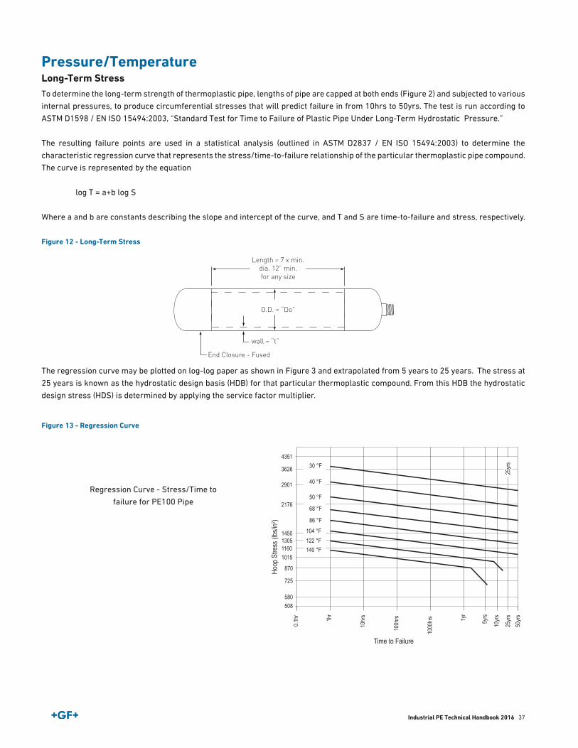
37Industrial PE Technical Handbook 2016
Pressure/TemperatureLong-Term StressTo determine the long-term strength of thermoplastic pipe, lengths of pipe are capped at both ends (Figure 2) and subjected to various
internal pressures, to produce circumferential stresses that will predict failure in from 10hrs to 50yrs . The test is run according to
ASTM D1598 / EN ISO 15494:2003, “Standard Test for Time to Failure of Plastic Pipe Under Long-Term Hydrostatic Pressure .”
The resulting failure points are used in a statistical analysis (outlined in ASTM D2837 / EN ISO 15494:2003) to determine the
characteristic regression curve that represents the stress/time-to-failure relationship of the particular thermoplastic pipe compound .
The curve is represented by the equation
log T = a+b log S
Where a and b are constants describing the slope and intercept of the curve, and T and S are time-to-failure and stress, respectively .
Figure 12 - Long-Term Stress
Length = 7 x min.dia. 12” min.for any size
O.D. = “Do”
wall = “t”
End Closure - Fused
The regression curve may be plotted on log-log paper as shown in Figure 3 and extrapolated from 5 years to 25 years . The stress at
25 years is known as the hydrostatic design basis (HDB) for that particular thermoplastic compound . From this HDB the hydrostatic
design stress (HDS) is determined by applying the service factor multiplier .
Figure 13 - Regression Curve
Hoop
Stre
ss (lb
s/in2 )
Time to Failure
508580
725
870
1015116013051450
2176
2901
3626
4351
0.1hr 1h
r
10hr
s
10yrs5y
rs1yr
1000
hrs
100h
rs
50yrs
86 °F
68 °F
50 °F
122 °F140 °F
104 °F
40 °F
30 °F
25yrs
25yrs
Regression Curve - Stress/Time to
failure for PE100 Pipe
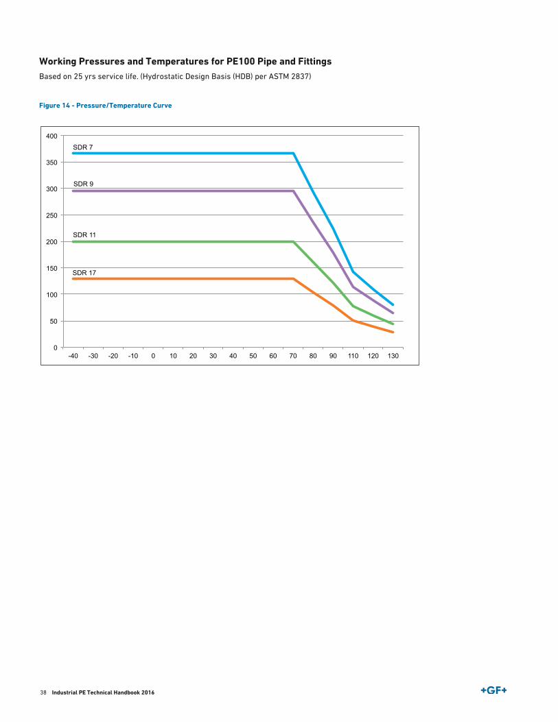
38 Industrial PE Technical Handbook 2016
Working Pressures and Temperatures for PE100 Pipe and FittingsBased on 25 yrs service life . (Hydrostatic Design Basis (HDB) per ASTM 2837)
Figure 14 - Pressure/Temperature Curve
0
50
100
150
200
250
300
350
400
-40 -30 -20 -10 0 10 20 30 40 50 60 70 80 90 110 120 130
SDR 17
SDR 11
SDR 9
SDR 7
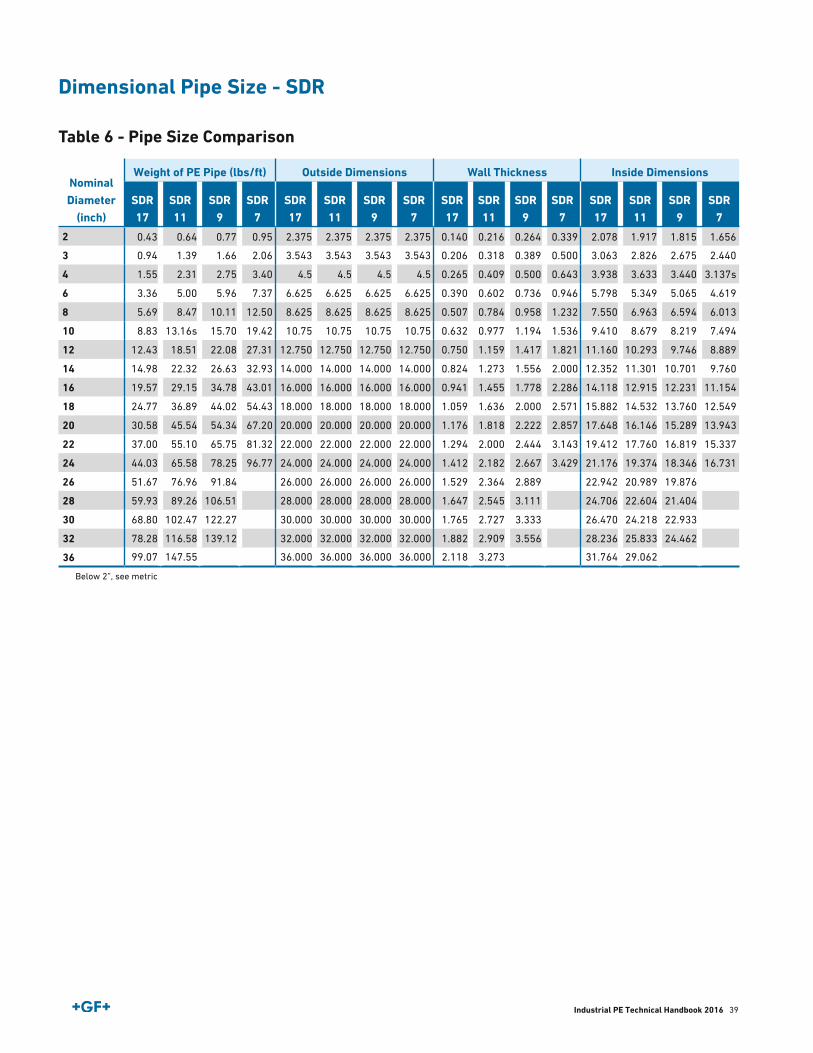
39Industrial PE Technical Handbook 2016
Dimensional Pipe Size - SDR
Table 6 - Pipe Size Comparison
NominalDiameter
(inch)
Weight of PE Pipe (lbs/ft) Outside Dimensions Wall Thickness Inside Dimensions
SDR 17
SDR 11
SDR 9
SDR 7
SDR 17
SDR 11
SDR 9
SDR 7
SDR 17
SDR 11
SDR 9
SDR 7
SDR 17
SDR 11
SDR 9
SDR 7
2 0 .43 0 .64 0 .77 0 .95 2 .375 2 .375 2 .375 2 .375 0 .140 0 .216 0 .264 0 .339 2 .078 1 .917 1 .815 1 .656
3 0 .94 1 .39 1 .66 2 .06 3 .543 3 .543 3 .543 3 .543 0 .206 0 .318 0 .389 0 .500 3 .063 2 .826 2 .675 2 .440
4 1 .55 2 .31 2 .75 3 .40 4 .5 4 .5 4 .5 4 .5 0 .265 0 .409 0 .500 0 .643 3 .938 3 .633 3 .440 3 .137s
6 3 .36 5 .00 5 .96 7 .37 6 .625 6 .625 6 .625 6 .625 0 .390 0 .602 0 .736 0 .946 5 .798 5 .349 5 .065 4 .619
8 5 .69 8 .47 10 .11 12 .50 8 .625 8 .625 8 .625 8 .625 0 .507 0 .784 0 .958 1 .232 7 .550 6 .963 6 .594 6 .013
10 8 .83 13 .16s 15 .70 19 .42 10 .75 10 .75 10 .75 10 .75 0 .632 0 .977 1 .194 1 .536 9 .410 8 .679 8 .219 7 .494
12 12 .43 18 .51 22 .08 27 .31 12 .750 12 .750 12 .750 12 .750 0 .750 1 .159 1 .417 1 .821 11 .160 10 .293 9 .746 8 .889
14 14 .98 22 .32 26 .63 32 .93 14 .000 14 .000 14 .000 14 .000 0 .824 1 .273 1 .556 2 .000 12 .352 11 .301 10 .701 9 .760
16 19 .57 29 .15 34 .78 43 .01 16 .000 16 .000 16 .000 16 .000 0 .941 1 .455 1 .778 2 .286 14 .118 12 .915 12 .231 11 .154
18 24 .77 36 .89 44 .02 54 .43 18 .000 18 .000 18 .000 18 .000 1 .059 1 .636 2 .000 2 .571 15 .882 14 .532 13 .760 12 .549
20 30 .58 45 .54 54 .34 67 .20 20 .000 20 .000 20 .000 20 .000 1 .176 1 .818 2 .222 2 .857 17 .648 16 .146 15 .289 13 .943
22 37 .00 55 .10 65 .75 81 .32 22 .000 22 .000 22 .000 22 .000 1 .294 2 .000 2 .444 3 .143 19 .412 17 .760 16 .819 15 .337
24 44 .03 65 .58 78 .25 96 .77 24 .000 24 .000 24 .000 24 .000 1 .412 2 .182 2 .667 3 .429 21 .176 19 .374 18 .346 16 .731
26 51 .67 76 .96 91 .84 26 .000 26 .000 26 .000 26 .000 1 .529 2 .364 2 .889 22 .942 20 .989 19 .876
28 59 .93 89 .26 106 .51 28 .000 28 .000 28 .000 28 .000 1 .647 2 .545 3 .111 24 .706 22 .604 21 .404
30 68 .80 102 .47 122 .27 30 .000 30 .000 30 .000 30 .000 1 .765 2 .727 3 .333 26 .470 24 .218 22 .933
32 78 .28 116 .58 139 .12 32 .000 32 .000 32 .000 32 .000 1 .882 2 .909 3 .556 28 .236 25 .833 24 .462
36 99 .07 147 .55 36 .000 36 .000 36 .000 36 .000 2 .118 3 .273 31 .764 29 .062
Below 2”, see metric
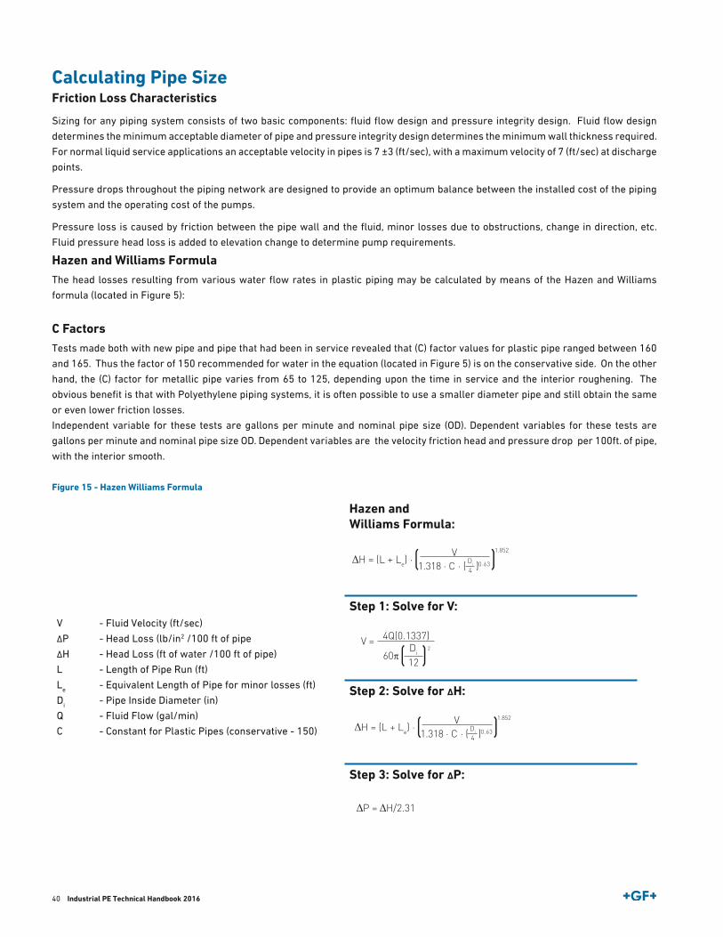
40 Industrial PE Technical Handbook 2016
Calculating Pipe SizeFriction Loss Characteristics
Sizing for any piping system consists of two basic components: fluid flow design and pressure integrity design . Fluid flow design
determines the minimum acceptable diameter of pipe and pressure integrity design determines the minimum wall thickness required .
For normal liquid service applications an acceptable velocity in pipes is 7 ±3 (ft/sec), with a maximum velocity of 7 (ft/sec) at discharge
points .
Pressure drops throughout the piping network are designed to provide an optimum balance between the installed cost of the piping
system and the operating cost of the pumps .
Pressure loss is caused by friction between the pipe wall and the fluid, minor losses due to obstructions, change in direction, etc .
Fluid pressure head loss is added to elevation change to determine pump requirements .
Hazen and Williams FormulaThe head losses resulting from various water flow rates in plastic piping may be calculated by means of the Hazen and Williams
formula (located in Figure 5):
C FactorsTests made both with new pipe and pipe that had been in service revealed that (C) factor values for plastic pipe ranged between 160
and 165 . Thus the factor of 150 recommended for water in the equation (located in Figure 5) is on the conservative side . On the other
hand, the (C) factor for metallic pipe varies from 65 to 125, depending upon the time in service and the interior roughening . The
obvious benefit is that with Polyethylene piping systems, it is often possible to use a smaller diameter pipe and still obtain the same
or even lower friction losses .
Independent variable for these tests are gallons per minute and nominal pipe size (OD) . Dependent variables for these tests are
gallons per minute and nominal pipe size OD . Dependent variables are the velocity friction head and pressure drop per 100ft . of pipe,
with the interior smooth .
Figure 15 - Hazen Williams Formula
V - Fluid Velocity (ft/sec)
∆P - Head Loss (lb/in2 /100 ft of pipe
∆H - Head Loss (ft of water /100 ft of pipe)
L - Length of Pipe Run (ft)
Le - Equivalent Length of Pipe for minor losses (ft)
Di - Pipe Inside Diameter (in)
Q - Fluid Flow (gal/min)
C - Constant for Plastic Pipes (conservative - 150)
Hazen and Williams Formula:
V = 4Q(0.1337)
( Di
12
2)60
ΔP = ΔH/2.31
ΔH = (L + Le) · V
1.318 · C · ( )0.63Di
4
1.852
( )
Step 1: Solve for V:
V = 4Q(0.1337)
( Di
12
2)60
ΔP = ΔH/2.31
ΔH = (L + Le) · V
1.318 · C · ( )0.63Di
4
1.852
( )Step 2: Solve for ∆H:
V = 4Q(0.1337)
( Di
12
2)60
ΔP = ΔH/2.31
ΔH = (L + Le) · V
1.318 · C · ( )0.63Di
4
1.852
( )
Step 3: Solve for ∆P:
V = 4Q(0.1337)
( Di
12
2)60
ΔP = ΔH/2.31
ΔH = (L + Le) · V
1.318 · C · ( )0.63Di
4
1.852
( )
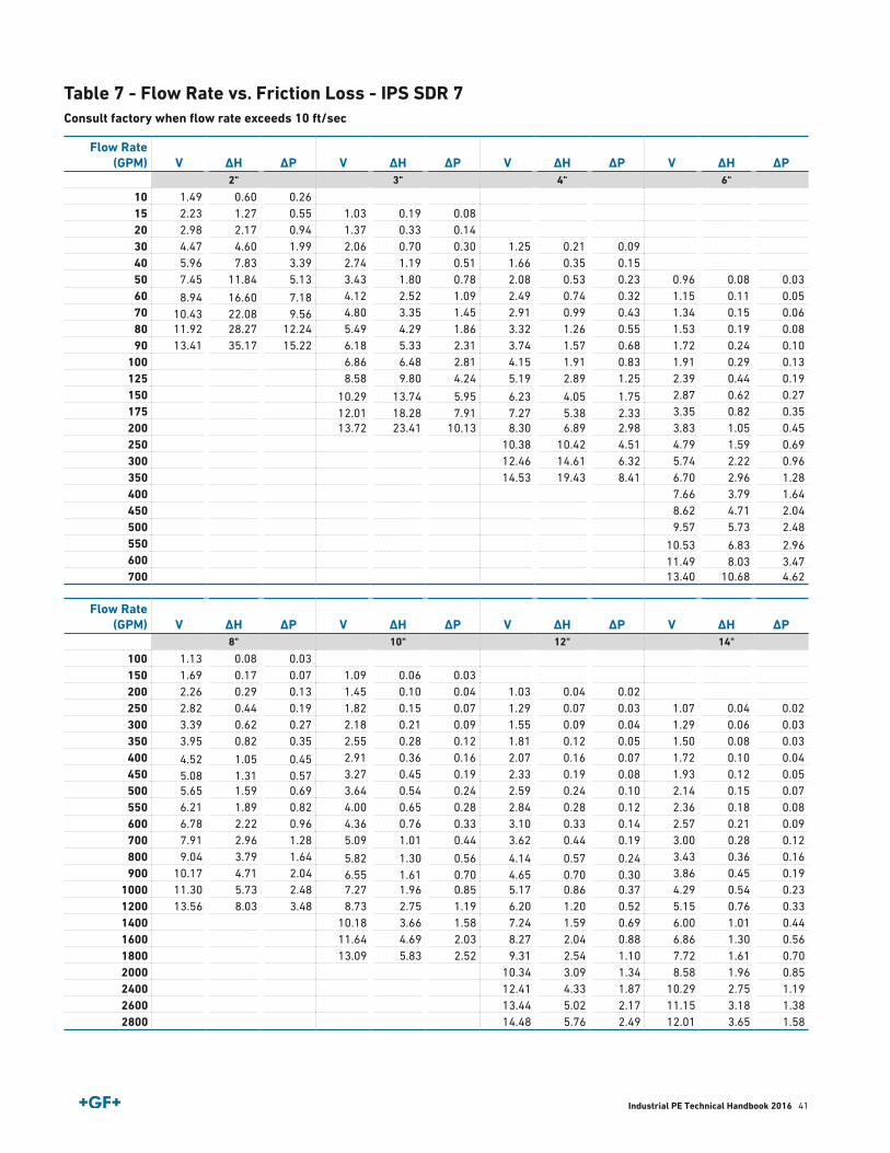
41Industrial PE Technical Handbook 2016
Table 7 - Flow Rate vs. Friction Loss - IPS SDR 7Consult factory when flow rate exceeds 10 ft/sec
Flow Rate (GPM) V ΔH ΔP V ΔH ΔP V ΔH ΔP V ΔH ΔP
2" 3" 4" 6"
10 1 .49 0 .60 0 .26 15 2 .23 1 .27 0 .55 1 .03 0 .19 0 .08 20 2 .98 2 .17 0 .94 1 .37 0 .33 0 .14 30 4 .47 4 .60 1 .99 2 .06 0 .70 0 .30 1 .25 0 .21 0 .09 40 5 .96 7 .83 3 .39 2 .74 1 .19 0 .51 1 .66 0 .35 0 .15 50 7 .45 11 .84 5 .13 3 .43 1 .80 0 .78 2 .08 0 .53 0 .23 0 .96 0 .08 0 .03 60 8 .94 16 .60 7 .18 4 .12 2 .52 1 .09 2 .49 0 .74 0 .32 1 .15 0 .11 0 .05 70 10 .43 22 .08 9 .56 4 .80 3 .35 1 .45 2 .91 0 .99 0 .43 1 .34 0 .15 0 .06 80 11 .92 28 .27 12 .24 5 .49 4 .29 1 .86 3 .32 1 .26 0 .55 1 .53 0 .19 0 .08 90 13 .41 35 .17 15 .22 6 .18 5 .33 2 .31 3 .74 1 .57 0 .68 1 .72 0 .24 0 .10
100 6 .86 6 .48 2 .81 4 .15 1 .91 0 .83 1 .91 0 .29 0 .13 125 8 .58 9 .80 4 .24 5 .19 2 .89 1 .25 2 .39 0 .44 0 .19 150 10 .29 13 .74 5 .95 6 .23 4 .05 1 .75 2 .87 0 .62 0 .27 175 12 .01 18 .28 7 .91 7 .27 5 .38 2 .33 3 .35 0 .82 0 .35 200 13 .72 23 .41 10 .13 8 .30 6 .89 2 .98 3 .83 1 .05 0 .45 250 10 .38 10 .42 4 .51 4 .79 1 .59 0 .69 300 12 .46 14 .61 6 .32 5 .74 2 .22 0 .96 350 14 .53 19 .43 8 .41 6 .70 2 .96 1 .28 400 7 .66 3 .79 1 .64 450 8 .62 4 .71 2 .04 500 9 .57 5 .73 2 .48 550 10 .53 6 .83 2 .96 600 11 .49 8 .03 3 .47 700 13 .40 10 .68 4 .62
Flow Rate (GPM) V ΔH ΔP V ΔH ΔP V ΔH ΔP V ΔH ΔP
8" 10" 12" 14"
100 1 .13 0 .08 0 .03 150 1 .69 0 .17 0 .07 1 .09 0 .06 0 .03 200 2 .26 0 .29 0 .13 1 .45 0 .10 0 .04 1 .03 0 .04 0 .02 250 2 .82 0 .44 0 .19 1 .82 0 .15 0 .07 1 .29 0 .07 0 .03 1 .07 0 .04 0 .02 300 3 .39 0 .62 0 .27 2 .18 0 .21 0 .09 1 .55 0 .09 0 .04 1 .29 0 .06 0 .03 350 3 .95 0 .82 0 .35 2 .55 0 .28 0 .12 1 .81 0 .12 0 .05 1 .50 0 .08 0 .03 400 4 .52 1 .05 0 .45 2 .91 0 .36 0 .16 2 .07 0 .16 0 .07 1 .72 0 .10 0 .04 450 5 .08 1 .31 0 .57 3 .27 0 .45 0 .19 2 .33 0 .19 0 .08 1 .93 0 .12 0 .05 500 5 .65 1 .59 0 .69 3 .64 0 .54 0 .24 2 .59 0 .24 0 .10 2 .14 0 .15 0 .07 550 6 .21 1 .89 0 .82 4 .00 0 .65 0 .28 2 .84 0 .28 0 .12 2 .36 0 .18 0 .08 600 6 .78 2 .22 0 .96 4 .36 0 .76 0 .33 3 .10 0 .33 0 .14 2 .57 0 .21 0 .09 700 7 .91 2 .96 1 .28 5 .09 1 .01 0 .44 3 .62 0 .44 0 .19 3 .00 0 .28 0 .12 800 9 .04 3 .79 1 .64 5 .82 1 .30 0 .56 4 .14 0 .57 0 .24 3 .43 0 .36 0 .16 900 10 .17 4 .71 2 .04 6 .55 1 .61 0 .70 4 .65 0 .70 0 .30 3 .86 0 .45 0 .19
1000 11 .30 5 .73 2 .48 7 .27 1 .96 0 .85 5 .17 0 .86 0 .37 4 .29 0 .54 0 .23 1200 13 .56 8 .03 3 .48 8 .73 2 .75 1 .19 6 .20 1 .20 0 .52 5 .15 0 .76 0 .33 1400 10 .18 3 .66 1 .58 7 .24 1 .59 0 .69 6 .00 1 .01 0 .44 1600 11 .64 4 .69 2 .03 8 .27 2 .04 0 .88 6 .86 1 .30 0 .56 1800 13 .09 5 .83 2 .52 9 .31 2 .54 1 .10 7 .72 1 .61 0 .70 2000 10 .34 3 .09 1 .34 8 .58 1 .96 0 .85 2400 12 .41 4 .33 1 .87 10 .29 2 .75 1 .19 2600 13 .44 5 .02 2 .17 11 .15 3 .18 1 .38 2800 14 .48 5 .76 2 .49 12 .01 3 .65 1 .58
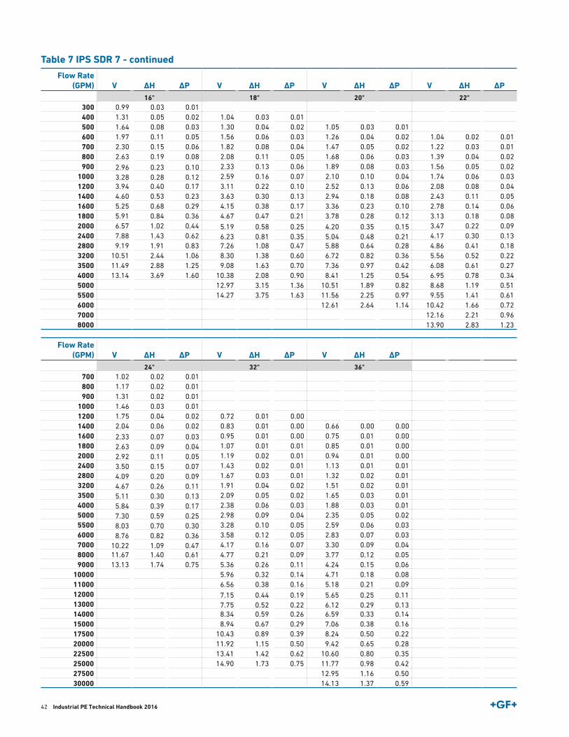
42 Industrial PE Technical Handbook 2016
Table 7 IPS SDR 7 - continued
Flow Rate (GPM) V ΔH ΔP V ΔH ΔP V ΔH ΔP V ΔH ΔP
16" 18" 20" 22"300 0 .99 0 .03 0 .01 400 1 .31 0 .05 0 .02 1 .04 0 .03 0 .01 500 1 .64 0 .08 0 .03 1 .30 0 .04 0 .02 1 .05 0 .03 0 .01 600 1 .97 0 .11 0 .05 1 .56 0 .06 0 .03 1 .26 0 .04 0 .02 1 .04 0 .02 0 .01 700 2 .30 0 .15 0 .06 1 .82 0 .08 0 .04 1 .47 0 .05 0 .02 1 .22 0 .03 0 .01 800 2 .63 0 .19 0 .08 2 .08 0 .11 0 .05 1 .68 0 .06 0 .03 1 .39 0 .04 0 .02 900 2 .96 0 .23 0 .10 2 .33 0 .13 0 .06 1 .89 0 .08 0 .03 1 .56 0 .05 0 .02
1000 3 .28 0 .28 0 .12 2 .59 0 .16 0 .07 2 .10 0 .10 0 .04 1 .74 0 .06 0 .03 1200 3 .94 0 .40 0 .17 3 .11 0 .22 0 .10 2 .52 0 .13 0 .06 2 .08 0 .08 0 .04 1400 4 .60 0 .53 0 .23 3 .63 0 .30 0 .13 2 .94 0 .18 0 .08 2 .43 0 .11 0 .05 1600 5 .25 0 .68 0 .29 4 .15 0 .38 0 .17 3 .36 0 .23 0 .10 2 .78 0 .14 0 .06 1800 5 .91 0 .84 0 .36 4 .67 0 .47 0 .21 3 .78 0 .28 0 .12 3 .13 0 .18 0 .08 2000 6 .57 1 .02 0 .44 5 .19 0 .58 0 .25 4 .20 0 .35 0 .15 3 .47 0 .22 0 .09 2400 7 .88 1 .43 0 .62 6 .23 0 .81 0 .35 5 .04 0 .48 0 .21 4 .17 0 .30 0 .13 2800 9 .19 1 .91 0 .83 7 .26 1 .08 0 .47 5 .88 0 .64 0 .28 4 .86 0 .41 0 .18 3200 10 .51 2 .44 1 .06 8 .30 1 .38 0 .60 6 .72 0 .82 0 .36 5 .56 0 .52 0 .22 3500 11 .49 2 .88 1 .25 9 .08 1 .63 0 .70 7 .36 0 .97 0 .42 6 .08 0 .61 0 .27 4000 13 .14 3 .69 1 .60 10 .38 2 .08 0 .90 8 .41 1 .25 0 .54 6 .95 0 .78 0 .34 5000 12 .97 3 .15 1 .36 10 .51 1 .89 0 .82 8 .68 1 .19 0 .51 5500 14 .27 3 .75 1 .63 11 .56 2 .25 0 .97 9 .55 1 .41 0 .61 6000 12 .61 2 .64 1 .14 10 .42 1 .66 0 .72 7000 12 .16 2 .21 0 .96 8000 13 .90 2 .83 1 .23
Flow Rate (GPM) V ΔH ΔP V ΔH ΔP V ΔH ΔP
24" 32" 36"700 1 .02 0 .02 0 .01 800 1 .17 0 .02 0 .01 900 1 .31 0 .02 0 .01
1000 1 .46 0 .03 0 .01 1200 1 .75 0 .04 0 .02 0 .72 0 .01 0 .00 1400 2 .04 0 .06 0 .02 0 .83 0 .01 0 .00 0 .66 0 .00 0 .00 1600 2 .33 0 .07 0 .03 0 .95 0 .01 0 .00 0 .75 0 .01 0 .00 1800 2 .63 0 .09 0 .04 1 .07 0 .01 0 .01 0 .85 0 .01 0 .00 2000 2 .92 0 .11 0 .05 1 .19 0 .02 0 .01 0 .94 0 .01 0 .00 2400 3 .50 0 .15 0 .07 1 .43 0 .02 0 .01 1 .13 0 .01 0 .01 2800 4 .09 0 .20 0 .09 1 .67 0 .03 0 .01 1 .32 0 .02 0 .01 3200 4 .67 0 .26 0 .11 1 .91 0 .04 0 .02 1 .51 0 .02 0 .01 3500 5 .11 0 .30 0 .13 2 .09 0 .05 0 .02 1 .65 0 .03 0 .01 4000 5 .84 0 .39 0 .17 2 .38 0 .06 0 .03 1 .88 0 .03 0 .01 5000 7 .30 0 .59 0 .25 2 .98 0 .09 0 .04 2 .35 0 .05 0 .02 5500 8 .03 0 .70 0 .30 3 .28 0 .10 0 .05 2 .59 0 .06 0 .03 6000 8 .76 0 .82 0 .36 3 .58 0 .12 0 .05 2 .83 0 .07 0 .03 7000 10 .22 1 .09 0 .47 4 .17 0 .16 0 .07 3 .30 0 .09 0 .04 8000 11 .67 1 .40 0 .61 4 .77 0 .21 0 .09 3 .77 0 .12 0 .05 9000 13 .13 1 .74 0 .75 5 .36 0 .26 0 .11 4 .24 0 .15 0 .06
10000 5 .96 0 .32 0 .14 4 .71 0 .18 0 .08 11000 6 .56 0 .38 0 .16 5 .18 0 .21 0 .09 12000 7 .15 0 .44 0 .19 5 .65 0 .25 0 .11 13000 7 .75 0 .52 0 .22 6 .12 0 .29 0 .13 14000 8 .34 0 .59 0 .26 6 .59 0 .33 0 .14 15000 8 .94 0 .67 0 .29 7 .06 0 .38 0 .16 17500 10 .43 0 .89 0 .39 8 .24 0 .50 0 .22 20000 11 .92 1 .15 0 .50 9 .42 0 .65 0 .28 22500 13 .41 1 .42 0 .62 10 .60 0 .80 0 .35 25000 14 .90 1 .73 0 .75 11 .77 0 .98 0 .42 27500 12 .95 1 .16 0 .50 30000 14 .13 1 .37 0 .59
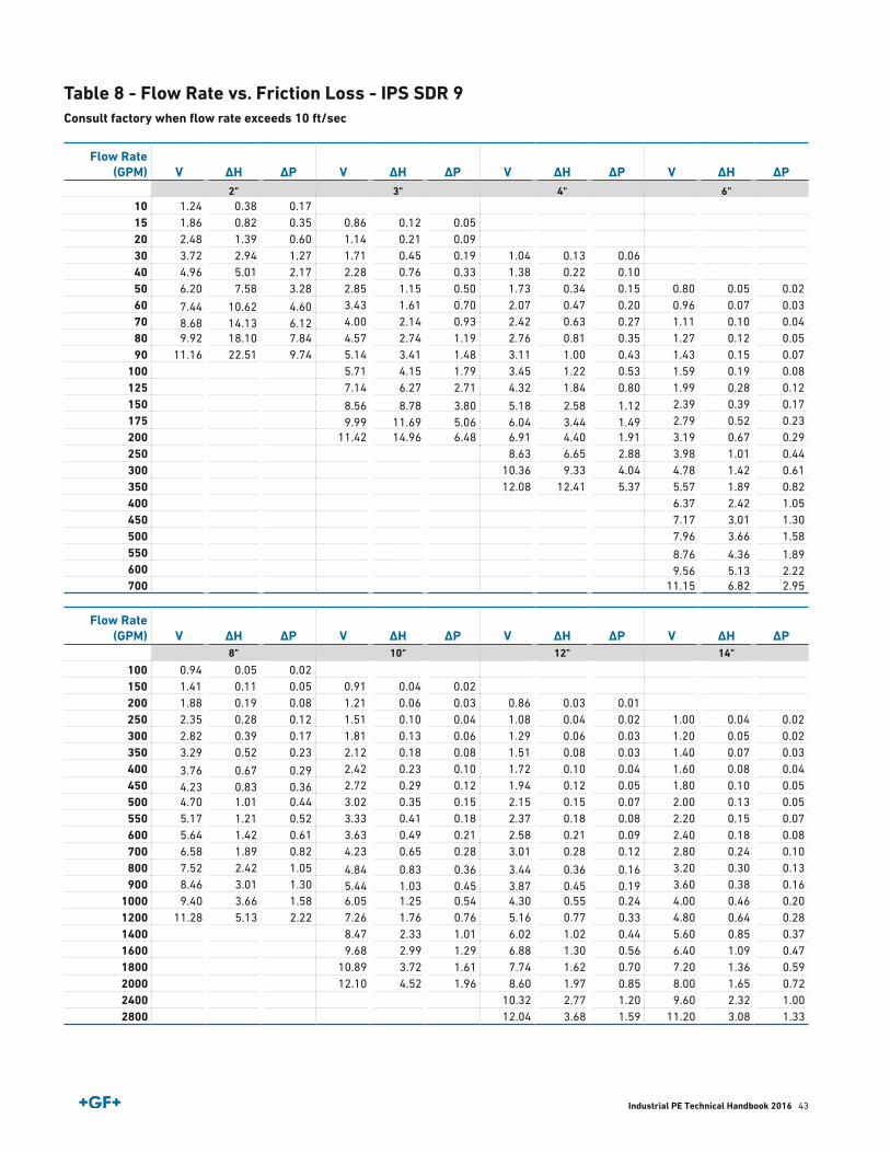
43Industrial PE Technical Handbook 2016
Table 8 - Flow Rate vs. Friction Loss - IPS SDR 9Consult factory when flow rate exceeds 10 ft/sec
Flow Rate (GPM) V ΔH ΔP V ΔH ΔP V ΔH ΔP V ΔH ΔP
2" 3" 4" 6"10 1 .24 0 .38 0 .17 15 1 .86 0 .82 0 .35 0 .86 0 .12 0 .05 20 2 .48 1 .39 0 .60 1 .14 0 .21 0 .09 30 3 .72 2 .94 1 .27 1 .71 0 .45 0 .19 1 .04 0 .13 0 .06 40 4 .96 5 .01 2 .17 2 .28 0 .76 0 .33 1 .38 0 .22 0 .10 50 6 .20 7 .58 3 .28 2 .85 1 .15 0 .50 1 .73 0 .34 0 .15 0 .80 0 .05 0 .02 60 7 .44 10 .62 4 .60 3 .43 1 .61 0 .70 2 .07 0 .47 0 .20 0 .96 0 .07 0 .03 70 8 .68 14 .13 6 .12 4 .00 2 .14 0 .93 2 .42 0 .63 0 .27 1 .11 0 .10 0 .04 80 9 .92 18 .10 7 .84 4 .57 2 .74 1 .19 2 .76 0 .81 0 .35 1 .27 0 .12 0 .05 90 11 .16 22 .51 9 .74 5 .14 3 .41 1 .48 3 .11 1 .00 0 .43 1 .43 0 .15 0 .07
100 5 .71 4 .15 1 .79 3 .45 1 .22 0 .53 1 .59 0 .19 0 .08 125 7 .14 6 .27 2 .71 4 .32 1 .84 0 .80 1 .99 0 .28 0 .12 150 8 .56 8 .78 3 .80 5 .18 2 .58 1 .12 2 .39 0 .39 0 .17 175 9 .99 11 .69 5 .06 6 .04 3 .44 1 .49 2 .79 0 .52 0 .23 200 11 .42 14 .96 6 .48 6 .91 4 .40 1 .91 3 .19 0 .67 0 .29 250 8 .63 6 .65 2 .88 3 .98 1 .01 0 .44 300 10 .36 9 .33 4 .04 4 .78 1 .42 0 .61 350 12 .08 12 .41 5 .37 5 .57 1 .89 0 .82 400 6 .37 2 .42 1 .05 450 7 .17 3 .01 1 .30 500 7 .96 3 .66 1 .58 550 8 .76 4 .36 1 .89 600 9 .56 5 .13 2 .22 700 11 .15 6 .82 2 .95
Flow Rate (GPM) V ΔH ΔP V ΔH ΔP V ΔH ΔP V ΔH ΔP
8" 10" 12" 14"
100 0 .94 0 .05 0 .02 150 1 .41 0 .11 0 .05 0 .91 0 .04 0 .02 200 1 .88 0 .19 0 .08 1 .21 0 .06 0 .03 0 .86 0 .03 0 .01 250 2 .35 0 .28 0 .12 1 .51 0 .10 0 .04 1 .08 0 .04 0 .02 1 .00 0 .04 0 .02 300 2 .82 0 .39 0 .17 1 .81 0 .13 0 .06 1 .29 0 .06 0 .03 1 .20 0 .05 0 .02 350 3 .29 0 .52 0 .23 2 .12 0 .18 0 .08 1 .51 0 .08 0 .03 1 .40 0 .07 0 .03 400 3 .76 0 .67 0 .29 2 .42 0 .23 0 .10 1 .72 0 .10 0 .04 1 .60 0 .08 0 .04 450 4 .23 0 .83 0 .36 2 .72 0 .29 0 .12 1 .94 0 .12 0 .05 1 .80 0 .10 0 .05 500 4 .70 1 .01 0 .44 3 .02 0 .35 0 .15 2 .15 0 .15 0 .07 2 .00 0 .13 0 .05 550 5 .17 1 .21 0 .52 3 .33 0 .41 0 .18 2 .37 0 .18 0 .08 2 .20 0 .15 0 .07 600 5 .64 1 .42 0 .61 3 .63 0 .49 0 .21 2 .58 0 .21 0 .09 2 .40 0 .18 0 .08 700 6 .58 1 .89 0 .82 4 .23 0 .65 0 .28 3 .01 0 .28 0 .12 2 .80 0 .24 0 .10 800 7 .52 2 .42 1 .05 4 .84 0 .83 0 .36 3 .44 0 .36 0 .16 3 .20 0 .30 0 .13 900 8 .46 3 .01 1 .30 5 .44 1 .03 0 .45 3 .87 0 .45 0 .19 3 .60 0 .38 0 .16
1000 9 .40 3 .66 1 .58 6 .05 1 .25 0 .54 4 .30 0 .55 0 .24 4 .00 0 .46 0 .20 1200 11 .28 5 .13 2 .22 7 .26 1 .76 0 .76 5 .16 0 .77 0 .33 4 .80 0 .64 0 .28 1400 8 .47 2 .33 1 .01 6 .02 1 .02 0 .44 5 .60 0 .85 0 .37 1600 9 .68 2 .99 1 .29 6 .88 1 .30 0 .56 6 .40 1 .09 0 .47 1800 10 .89 3 .72 1 .61 7 .74 1 .62 0 .70 7 .20 1 .36 0 .59 2000 12 .10 4 .52 1 .96 8 .60 1 .97 0 .85 8 .00 1 .65 0 .72 2400 10 .32 2 .77 1 .20 9 .60 2 .32 1 .00 2800 12 .04 3 .68 1 .59 11 .20 3 .08 1 .33
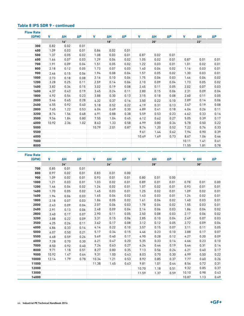
44 Industrial PE Technical Handbook 2016
Table 8 IPS SDR 9 - continued
Flow Rate (GPM) V ΔH ΔP V ΔH ΔP V ΔH ΔP V ΔH ΔP
16" 18" 20" 22"300 0 .82 0 .02 0 .01 400 1 .09 0 .03 0 .01 0 .86 0 .02 0 .01 500 1 .37 0 .05 0 .02 1 .08 0 .03 0 .01 0 .87 0 .02 0 .01 600 1 .64 0 .07 0 .03 1 .29 0 .04 0 .02 1 .05 0 .02 0 .01 0 .87 0 .01 0 .01 700 1 .91 0 .09 0 .04 1 .51 0 .05 0 .02 1 .22 0 .03 0 .01 1 .01 0 .02 0 .01 800 2 .18 0 .12 0 .05 1 .73 0 .07 0 .03 1 .40 0 .04 0 .02 1 .16 0 .03 0 .01 900 2 .46 0 .15 0 .06 1 .94 0 .08 0 .04 1 .57 0 .05 0 .02 1 .30 0 .03 0 .01
1000 2 .73 0 .18 0 .08 2 .16 0 .10 0 .04 1 .75 0 .06 0 .03 1 .44 0 .04 0 .02 1200 3 .28 0 .25 0 .11 2 .59 0 .14 0 .06 2 .10 0 .09 0 .04 1 .73 0 .05 0 .02 1400 3 .82 0 .34 0 .15 3 .02 0 .19 0 .08 2 .45 0 .11 0 .05 2 .02 0 .07 0 .03 1600 4 .37 0 .43 0 .19 3 .45 0 .24 0 .11 2 .80 0 .15 0 .06 2 .31 0 .09 0 .04 1800 4 .92 0 .54 0 .23 3 .88 0 .30 0 .13 3 .15 0 .18 0 .08 2 .60 0 .11 0 .05 2000 5 .46 0 .65 0 .28 4 .32 0 .37 0 .16 3 .50 0 .22 0 .10 2 .89 0 .14 0 .06 2400 6 .55 0 .92 0 .40 5 .18 0 .52 0 .22 4 .19 0 .31 0 .13 3 .47 0 .19 0 .08 2800 7 .65 1 .22 0 .53 6 .04 0 .69 0 .30 4 .89 0 .41 0 .18 4 .04 0 .26 0 .11 3200 8 .74 1 .56 0 .68 6 .91 0 .88 0 .38 5 .59 0 .53 0 .23 4 .62 0 .33 0 .14 3500 9 .56 1 .84 0 .80 7 .55 1 .04 0 .45 6 .12 0 .62 0 .27 5 .05 0 .39 0 .17 4000 10 .92 2 .36 1 .02 8 .63 1 .33 0 .58 6 .99 0 .80 0 .34 5 .78 0 .50 0 .22 5000 10 .79 2 .01 0 .87 8 .74 1 .20 0 .52 7 .22 0 .76 0 .33 5500 9 .61 1 .44 0 .62 7 .94 0 .90 0 .39 6000 10 .49 1 .69 0 .73 8 .67 1 .06 0 .46 7000 10 .11 1 .41 0 .61 8000 11 .55 1 .81 0 .78
Flow Rate (GPM) V ΔH ΔP V ΔH ΔP V ΔH ΔP V ΔH ΔP
24" 26" 28" 30"700 0 .85 0 .01 0 .01 800 0 .97 0 .02 0 .01 0 .83 0 .01 0 .00 900 1 .09 0 .02 0 .01 0 .93 0 .01 0 .01 0 .80 0 .01 0 .00
1000 1 .21 0 .03 0 .01 1 .03 0 .02 0 .01 0 .89 0 .01 0 .01 0 .78 0 .01 0 .00 1200 1 .46 0 .04 0 .02 1 .24 0 .02 0 .01 1 .07 0 .02 0 .01 0 .93 0 .01 0 .01 1400 1 .70 0 .05 0 .02 1 .45 0 .03 0 .01 1 .25 0 .02 0 .01 1 .09 0 .02 0 .01 1600 1 .94 0 .06 0 .03 1 .65 0 .04 0 .02 1 .43 0 .03 0 .01 1 .24 0 .02 0 .01 1800 2 .18 0 .07 0 .03 1 .86 0 .05 0 .02 1 .61 0 .04 0 .02 1 .40 0 .03 0 .01 2000 2 .43 0 .09 0 .04 2 .07 0 .06 0 .03 1 .78 0 .04 0 .02 1 .55 0 .03 0 .01 2400 2 .91 0 .13 0 .06 2 .48 0 .09 0 .04 2 .14 0 .06 0 .03 1 .86 0 .04 0 .02 2800 3 .40 0 .17 0 .07 2 .90 0 .11 0 .05 2 .50 0 .08 0 .03 2 .17 0 .06 0 .02 3200 3 .88 0 .22 0 .09 3 .31 0 .15 0 .06 2 .85 0 .10 0 .04 2 .49 0 .07 0 .03 3500 4 .25 0 .26 0 .11 3 .62 0 .17 0 .08 3 .12 0 .12 0 .05 2 .72 0 .09 0 .04 4000 4 .86 0 .33 0 .14 4 .14 0 .22 0 .10 3 .57 0 .15 0 .07 3 .11 0 .11 0 .05 5000 6 .07 0 .50 0 .21 5 .17 0 .34 0 .15 4 .46 0 .23 0 .10 3 .88 0 .17 0 .07 5500 6 .68 0 .59 0 .26 5 .69 0 .40 0 .17 4 .90 0 .28 0 .12 4 .27 0 .20 0 .09 6000 7 .28 0 .70 0 .30 6 .21 0 .47 0 .20 5 .35 0 .33 0 .14 4 .66 0 .23 0 .10 7000 8 .50 0 .92 0 .40 7 .24 0 .63 0 .27 6 .24 0 .44 0 .19 5 .44 0 .31 0 .14 8000 9 .71 1 .18 0 .51 8 .27 0 .80 0 .35 7 .13 0 .56 0 .24 6 .21 0 .40 0 .17 9000 10 .92 1 .47 0 .64 9 .31 1 .00 0 .43 8 .03 0 .70 0 .30 6 .99 0 .50 0 .22
10000 12 .14 1 .79 0 .78 10 .34 1 .21 0 .53 8 .92 0 .85 0 .37 7 .77 0 .60 0 .26 11000 11 .38 1 .45 0 .63 9 .81 1 .01 0 .44 8 .54 0 .72 0 .31 12000 10 .70 1 .18 0 .51 9 .32 0 .85 0 .37 13000 11 .59 1 .37 0 .59 10 .10 0 .98 0 .43 14000 10 .87 1 .13 0 .49
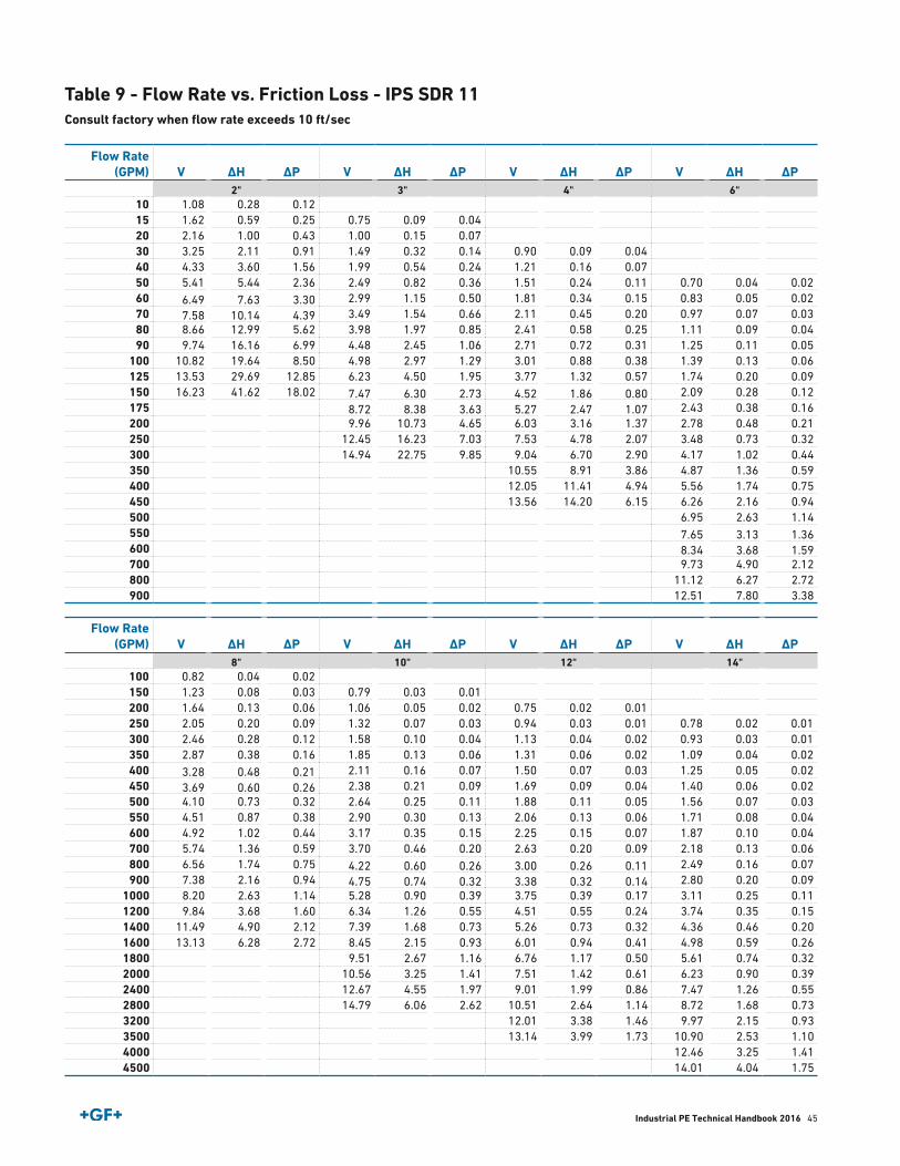
45Industrial PE Technical Handbook 2016
Table 9 - Flow Rate vs. Friction Loss - IPS SDR 11Consult factory when flow rate exceeds 10 ft/sec
Flow Rate (GPM) V ΔH ΔP V ΔH ΔP V ΔH ΔP V ΔH ΔP
2" 3" 4" 6"10 1 .08 0 .28 0 .12 15 1 .62 0 .59 0 .25 0 .75 0 .09 0 .04 20 2 .16 1 .00 0 .43 1 .00 0 .15 0 .07 30 3 .25 2 .11 0 .91 1 .49 0 .32 0 .14 0 .90 0 .09 0 .04 40 4 .33 3 .60 1 .56 1 .99 0 .54 0 .24 1 .21 0 .16 0 .07 50 5 .41 5 .44 2 .36 2 .49 0 .82 0 .36 1 .51 0 .24 0 .11 0 .70 0 .04 0 .02 60 6 .49 7 .63 3 .30 2 .99 1 .15 0 .50 1 .81 0 .34 0 .15 0 .83 0 .05 0 .02 70 7 .58 10 .14 4 .39 3 .49 1 .54 0 .66 2 .11 0 .45 0 .20 0 .97 0 .07 0 .03 80 8 .66 12 .99 5 .62 3 .98 1 .97 0 .85 2 .41 0 .58 0 .25 1 .11 0 .09 0 .04 90 9 .74 16 .16 6 .99 4 .48 2 .45 1 .06 2 .71 0 .72 0 .31 1 .25 0 .11 0 .05
100 10 .82 19 .64 8 .50 4 .98 2 .97 1 .29 3 .01 0 .88 0 .38 1 .39 0 .13 0 .06 125 13 .53 29 .69 12 .85 6 .23 4 .50 1 .95 3 .77 1 .32 0 .57 1 .74 0 .20 0 .09 150 16 .23 41 .62 18 .02 7 .47 6 .30 2 .73 4 .52 1 .86 0 .80 2 .09 0 .28 0 .12 175 8 .72 8 .38 3 .63 5 .27 2 .47 1 .07 2 .43 0 .38 0 .16 200 9 .96 10 .73 4 .65 6 .03 3 .16 1 .37 2 .78 0 .48 0 .21 250 12 .45 16 .23 7 .03 7 .53 4 .78 2 .07 3 .48 0 .73 0 .32 300 14 .94 22 .75 9 .85 9 .04 6 .70 2 .90 4 .17 1 .02 0 .44 350 10 .55 8 .91 3 .86 4 .87 1 .36 0 .59 400 12 .05 11 .41 4 .94 5 .56 1 .74 0 .75 450 13 .56 14 .20 6 .15 6 .26 2 .16 0 .94 500 6 .95 2 .63 1 .14 550 7 .65 3 .13 1 .36 600 8 .34 3 .68 1 .59 700 9 .73 4 .90 2 .12 800 11 .12 6 .27 2 .72 900 12 .51 7 .80 3 .38
Flow Rate (GPM) V ΔH ΔP V ΔH ΔP V ΔH ΔP V ΔH ΔP
8" 10" 12" 14"100 0 .82 0 .04 0 .02 150 1 .23 0 .08 0 .03 0 .79 0 .03 0 .01 200 1 .64 0 .13 0 .06 1 .06 0 .05 0 .02 0 .75 0 .02 0 .01 250 2 .05 0 .20 0 .09 1 .32 0 .07 0 .03 0 .94 0 .03 0 .01 0 .78 0 .02 0 .01 300 2 .46 0 .28 0 .12 1 .58 0 .10 0 .04 1 .13 0 .04 0 .02 0 .93 0 .03 0 .01 350 2 .87 0 .38 0 .16 1 .85 0 .13 0 .06 1 .31 0 .06 0 .02 1 .09 0 .04 0 .02 400 3 .28 0 .48 0 .21 2 .11 0 .16 0 .07 1 .50 0 .07 0 .03 1 .25 0 .05 0 .02 450 3 .69 0 .60 0 .26 2 .38 0 .21 0 .09 1 .69 0 .09 0 .04 1 .40 0 .06 0 .02 500 4 .10 0 .73 0 .32 2 .64 0 .25 0 .11 1 .88 0 .11 0 .05 1 .56 0 .07 0 .03 550 4 .51 0 .87 0 .38 2 .90 0 .30 0 .13 2 .06 0 .13 0 .06 1 .71 0 .08 0 .04 600 4 .92 1 .02 0 .44 3 .17 0 .35 0 .15 2 .25 0 .15 0 .07 1 .87 0 .10 0 .04 700 5 .74 1 .36 0 .59 3 .70 0 .46 0 .20 2 .63 0 .20 0 .09 2 .18 0 .13 0 .06 800 6 .56 1 .74 0 .75 4 .22 0 .60 0 .26 3 .00 0 .26 0 .11 2 .49 0 .16 0 .07 900 7 .38 2 .16 0 .94 4 .75 0 .74 0 .32 3 .38 0 .32 0 .14 2 .80 0 .20 0 .09
1000 8 .20 2 .63 1 .14 5 .28 0 .90 0 .39 3 .75 0 .39 0 .17 3 .11 0 .25 0 .11 1200 9 .84 3 .68 1 .60 6 .34 1 .26 0 .55 4 .51 0 .55 0 .24 3 .74 0 .35 0 .15 1400 11 .49 4 .90 2 .12 7 .39 1 .68 0 .73 5 .26 0 .73 0 .32 4 .36 0 .46 0 .20 1600 13 .13 6 .28 2 .72 8 .45 2 .15 0 .93 6 .01 0 .94 0 .41 4 .98 0 .59 0 .26 1800 9 .51 2 .67 1 .16 6 .76 1 .17 0 .50 5 .61 0 .74 0 .32 2000 10 .56 3 .25 1 .41 7 .51 1 .42 0 .61 6 .23 0 .90 0 .39 2400 12 .67 4 .55 1 .97 9 .01 1 .99 0 .86 7 .47 1 .26 0 .55 2800 14 .79 6 .06 2 .62 10 .51 2 .64 1 .14 8 .72 1 .68 0 .73 3200 12 .01 3 .38 1 .46 9 .97 2 .15 0 .93 3500 13 .14 3 .99 1 .73 10 .90 2 .53 1 .10 4000 12 .46 3 .25 1 .41 4500 14 .01 4 .04 1 .75
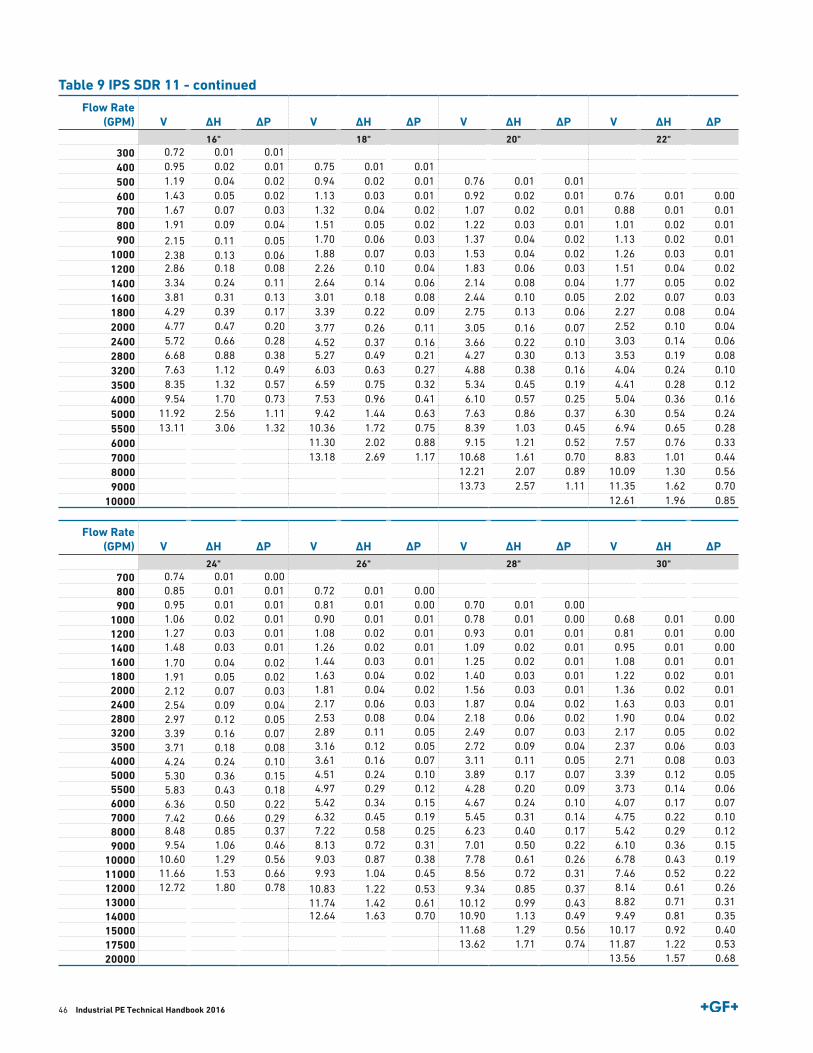
46 Industrial PE Technical Handbook 2016
Table 9 IPS SDR 11 - continued
Flow Rate (GPM) V ΔH ΔP V ΔH ΔP V ΔH ΔP V ΔH ΔP
16" 18" 20" 22"300 0 .72 0 .01 0 .01 400 0 .95 0 .02 0 .01 0 .75 0 .01 0 .01 500 1 .19 0 .04 0 .02 0 .94 0 .02 0 .01 0 .76 0 .01 0 .01 600 1 .43 0 .05 0 .02 1 .13 0 .03 0 .01 0 .92 0 .02 0 .01 0 .76 0 .01 0 .00 700 1 .67 0 .07 0 .03 1 .32 0 .04 0 .02 1 .07 0 .02 0 .01 0 .88 0 .01 0 .01 800 1 .91 0 .09 0 .04 1 .51 0 .05 0 .02 1 .22 0 .03 0 .01 1 .01 0 .02 0 .01 900 2 .15 0 .11 0 .05 1 .70 0 .06 0 .03 1 .37 0 .04 0 .02 1 .13 0 .02 0 .01
1000 2 .38 0 .13 0 .06 1 .88 0 .07 0 .03 1 .53 0 .04 0 .02 1 .26 0 .03 0 .01 1200 2 .86 0 .18 0 .08 2 .26 0 .10 0 .04 1 .83 0 .06 0 .03 1 .51 0 .04 0 .02 1400 3 .34 0 .24 0 .11 2 .64 0 .14 0 .06 2 .14 0 .08 0 .04 1 .77 0 .05 0 .02 1600 3 .81 0 .31 0 .13 3 .01 0 .18 0 .08 2 .44 0 .10 0 .05 2 .02 0 .07 0 .03 1800 4 .29 0 .39 0 .17 3 .39 0 .22 0 .09 2 .75 0 .13 0 .06 2 .27 0 .08 0 .04 2000 4 .77 0 .47 0 .20 3 .77 0 .26 0 .11 3 .05 0 .16 0 .07 2 .52 0 .10 0 .04 2400 5 .72 0 .66 0 .28 4 .52 0 .37 0 .16 3 .66 0 .22 0 .10 3 .03 0 .14 0 .06 2800 6 .68 0 .88 0 .38 5 .27 0 .49 0 .21 4 .27 0 .30 0 .13 3 .53 0 .19 0 .08 3200 7 .63 1 .12 0 .49 6 .03 0 .63 0 .27 4 .88 0 .38 0 .16 4 .04 0 .24 0 .10 3500 8 .35 1 .32 0 .57 6 .59 0 .75 0 .32 5 .34 0 .45 0 .19 4 .41 0 .28 0 .12 4000 9 .54 1 .70 0 .73 7 .53 0 .96 0 .41 6 .10 0 .57 0 .25 5 .04 0 .36 0 .16 5000 11 .92 2 .56 1 .11 9 .42 1 .44 0 .63 7 .63 0 .86 0 .37 6 .30 0 .54 0 .24 5500 13 .11 3 .06 1 .32 10 .36 1 .72 0 .75 8 .39 1 .03 0 .45 6 .94 0 .65 0 .28 6000 11 .30 2 .02 0 .88 9 .15 1 .21 0 .52 7 .57 0 .76 0 .33 7000 13 .18 2 .69 1 .17 10 .68 1 .61 0 .70 8 .83 1 .01 0 .44 8000 12 .21 2 .07 0 .89 10 .09 1 .30 0 .56 9000 13 .73 2 .57 1 .11 11 .35 1 .62 0 .70
10000 12 .61 1 .96 0 .85
Flow Rate (GPM) V ΔH ΔP V ΔH ΔP V ΔH ΔP V ΔH ΔP
24" 26" 28" 30"700 0 .74 0 .01 0 .00 800 0 .85 0 .01 0 .01 0 .72 0 .01 0 .00 900 0 .95 0 .01 0 .01 0 .81 0 .01 0 .00 0 .70 0 .01 0 .00
1000 1 .06 0 .02 0 .01 0 .90 0 .01 0 .01 0 .78 0 .01 0 .00 0 .68 0 .01 0 .00 1200 1 .27 0 .03 0 .01 1 .08 0 .02 0 .01 0 .93 0 .01 0 .01 0 .81 0 .01 0 .00 1400 1 .48 0 .03 0 .01 1 .26 0 .02 0 .01 1 .09 0 .02 0 .01 0 .95 0 .01 0 .00 1600 1 .70 0 .04 0 .02 1 .44 0 .03 0 .01 1 .25 0 .02 0 .01 1 .08 0 .01 0 .01 1800 1 .91 0 .05 0 .02 1 .63 0 .04 0 .02 1 .40 0 .03 0 .01 1 .22 0 .02 0 .01 2000 2 .12 0 .07 0 .03 1 .81 0 .04 0 .02 1 .56 0 .03 0 .01 1 .36 0 .02 0 .01 2400 2 .54 0 .09 0 .04 2 .17 0 .06 0 .03 1 .87 0 .04 0 .02 1 .63 0 .03 0 .01 2800 2 .97 0 .12 0 .05 2 .53 0 .08 0 .04 2 .18 0 .06 0 .02 1 .90 0 .04 0 .02 3200 3 .39 0 .16 0 .07 2 .89 0 .11 0 .05 2 .49 0 .07 0 .03 2 .17 0 .05 0 .02 3500 3 .71 0 .18 0 .08 3 .16 0 .12 0 .05 2 .72 0 .09 0 .04 2 .37 0 .06 0 .03 4000 4 .24 0 .24 0 .10 3 .61 0 .16 0 .07 3 .11 0 .11 0 .05 2 .71 0 .08 0 .03 5000 5 .30 0 .36 0 .15 4 .51 0 .24 0 .10 3 .89 0 .17 0 .07 3 .39 0 .12 0 .05 5500 5 .83 0 .43 0 .18 4 .97 0 .29 0 .12 4 .28 0 .20 0 .09 3 .73 0 .14 0 .06 6000 6 .36 0 .50 0 .22 5 .42 0 .34 0 .15 4 .67 0 .24 0 .10 4 .07 0 .17 0 .07 7000 7 .42 0 .66 0 .29 6 .32 0 .45 0 .19 5 .45 0 .31 0 .14 4 .75 0 .22 0 .10 8000 8 .48 0 .85 0 .37 7 .22 0 .58 0 .25 6 .23 0 .40 0 .17 5 .42 0 .29 0 .12 9000 9 .54 1 .06 0 .46 8 .13 0 .72 0 .31 7 .01 0 .50 0 .22 6 .10 0 .36 0 .15
10000 10 .60 1 .29 0 .56 9 .03 0 .87 0 .38 7 .78 0 .61 0 .26 6 .78 0 .43 0 .19 11000 11 .66 1 .53 0 .66 9 .93 1 .04 0 .45 8 .56 0 .72 0 .31 7 .46 0 .52 0 .22 12000 12 .72 1 .80 0 .78 10 .83 1 .22 0 .53 9 .34 0 .85 0 .37 8 .14 0 .61 0 .26 13000 11 .74 1 .42 0 .61 10 .12 0 .99 0 .43 8 .82 0 .71 0 .31 14000 12 .64 1 .63 0 .70 10 .90 1 .13 0 .49 9 .49 0 .81 0 .35 15000 11 .68 1 .29 0 .56 10 .17 0 .92 0 .40 17500 13 .62 1 .71 0 .74 11 .87 1 .22 0 .53 20000 13 .56 1 .57 0 .68
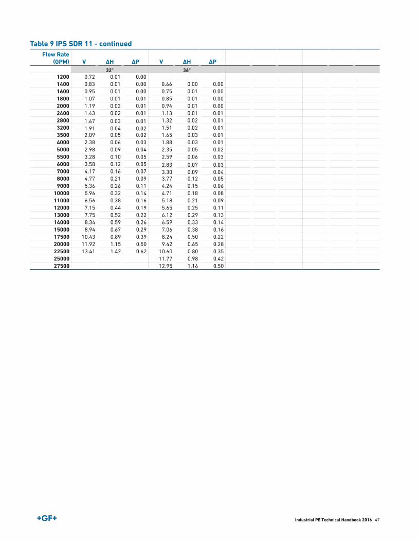
47Industrial PE Technical Handbook 2016
Table 9 IPS SDR 11 - continued Flow Rate
(GPM) V ΔH ΔP V ΔH ΔP32" 36"
1200 0 .72 0 .01 0 .00 1400 0 .83 0 .01 0 .00 0 .66 0 .00 0 .00 1600 0 .95 0 .01 0 .00 0 .75 0 .01 0 .00 1800 1 .07 0 .01 0 .01 0 .85 0 .01 0 .00 2000 1 .19 0 .02 0 .01 0 .94 0 .01 0 .00 2400 1 .43 0 .02 0 .01 1 .13 0 .01 0 .01 2800 1 .67 0 .03 0 .01 1 .32 0 .02 0 .01 3200 1 .91 0 .04 0 .02 1 .51 0 .02 0 .01 3500 2 .09 0 .05 0 .02 1 .65 0 .03 0 .01 4000 2 .38 0 .06 0 .03 1 .88 0 .03 0 .01 5000 2 .98 0 .09 0 .04 2 .35 0 .05 0 .02 5500 3 .28 0 .10 0 .05 2 .59 0 .06 0 .03 6000 3 .58 0 .12 0 .05 2 .83 0 .07 0 .03 7000 4 .17 0 .16 0 .07 3 .30 0 .09 0 .04 8000 4 .77 0 .21 0 .09 3 .77 0 .12 0 .05 9000 5 .36 0 .26 0 .11 4 .24 0 .15 0 .06
10000 5 .96 0 .32 0 .14 4 .71 0 .18 0 .08 11000 6 .56 0 .38 0 .16 5 .18 0 .21 0 .09 12000 7 .15 0 .44 0 .19 5 .65 0 .25 0 .11 13000 7 .75 0 .52 0 .22 6 .12 0 .29 0 .13 14000 8 .34 0 .59 0 .26 6 .59 0 .33 0 .14 15000 8 .94 0 .67 0 .29 7 .06 0 .38 0 .16 17500 10 .43 0 .89 0 .39 8 .24 0 .50 0 .22 20000 11 .92 1 .15 0 .50 9 .42 0 .65 0 .28 22500 13 .41 1 .42 0 .62 10 .60 0 .80 0 .35 25000 11 .77 0 .98 0 .42 27500 12 .95 1 .16 0 .50
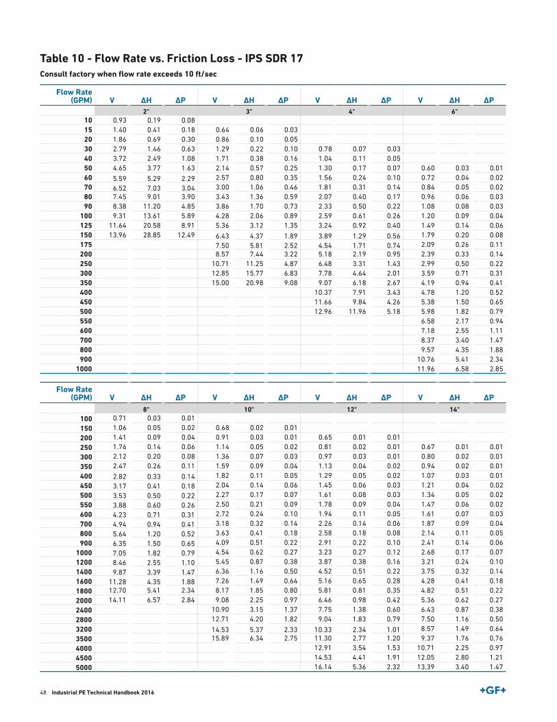
48 Industrial PE Technical Handbook 2016
Table 10 - Flow Rate vs. Friction Loss - IPS SDR 17Consult factory when flow rate exceeds 10 ft/sec
Flow Rate (GPM) V ΔH ΔP V ΔH ΔP V ΔH ΔP V ΔH ΔP
2" 3" 4" 6"10 0 .93 0 .19 0 .08 15 1 .40 0 .41 0 .18 0 .64 0 .06 0 .03 20 1 .86 0 .69 0 .30 0 .86 0 .10 0 .05 30 2 .79 1 .46 0 .63 1 .29 0 .22 0 .10 0 .78 0 .07 0 .03 40 3 .72 2 .49 1 .08 1 .71 0 .38 0 .16 1 .04 0 .11 0 .05 50 4 .65 3 .77 1 .63 2 .14 0 .57 0 .25 1 .30 0 .17 0 .07 0 .60 0 .03 0 .01 60 5 .59 5 .29 2 .29 2 .57 0 .80 0 .35 1 .56 0 .24 0 .10 0 .72 0 .04 0 .02 70 6 .52 7 .03 3 .04 3 .00 1 .06 0 .46 1 .81 0 .31 0 .14 0 .84 0 .05 0 .02 80 7 .45 9 .01 3 .90 3 .43 1 .36 0 .59 2 .07 0 .40 0 .17 0 .96 0 .06 0 .03 90 8 .38 11 .20 4 .85 3 .86 1 .70 0 .73 2 .33 0 .50 0 .22 1 .08 0 .08 0 .03
100 9 .31 13 .61 5 .89 4 .28 2 .06 0 .89 2 .59 0 .61 0 .26 1 .20 0 .09 0 .04 125 11 .64 20 .58 8 .91 5 .36 3 .12 1 .35 3 .24 0 .92 0 .40 1 .49 0 .14 0 .06 150 13 .96 28 .85 12 .49 6 .43 4 .37 1 .89 3 .89 1 .29 0 .56 1 .79 0 .20 0 .08 175 7 .50 5 .81 2 .52 4 .54 1 .71 0 .74 2 .09 0 .26 0 .11 200 8 .57 7 .44 3 .22 5 .18 2 .19 0 .95 2 .39 0 .33 0 .14 250 10 .71 11 .25 4 .87 6 .48 3 .31 1 .43 2 .99 0 .50 0 .22 300 12 .85 15 .77 6 .83 7 .78 4 .64 2 .01 3 .59 0 .71 0 .31 350 15 .00 20 .98 9 .08 9 .07 6 .18 2 .67 4 .19 0 .94 0 .41 400 10 .37 7 .91 3 .43 4 .78 1 .20 0 .52 450 11 .66 9 .84 4 .26 5 .38 1 .50 0 .65 500 12 .96 11 .96 5 .18 5 .98 1 .82 0 .79 550 6 .58 2 .17 0 .94 600 7 .18 2 .55 1 .11 700 8 .37 3 .40 1 .47 800 9 .57 4 .35 1 .88 900 10 .76 5 .41 2 .34
1000 11 .96 6 .58 2 .85
Flow Rate (GPM) V ΔH ΔP V ΔH ΔP V ΔH ΔP V ΔH ΔP
8" 10" 12" 14"100 0 .71 0 .03 0 .01 150 1 .06 0 .05 0 .02 0 .68 0 .02 0 .01 200 1 .41 0 .09 0 .04 0 .91 0 .03 0 .01 0 .65 0 .01 0 .01 250 1 .76 0 .14 0 .06 1 .14 0 .05 0 .02 0 .81 0 .02 0 .01 0 .67 0 .01 0 .01 300 2 .12 0 .20 0 .08 1 .36 0 .07 0 .03 0 .97 0 .03 0 .01 0 .80 0 .02 0 .01 350 2 .47 0 .26 0 .11 1 .59 0 .09 0 .04 1 .13 0 .04 0 .02 0 .94 0 .02 0 .01 400 2 .82 0 .33 0 .14 1 .82 0 .11 0 .05 1 .29 0 .05 0 .02 1 .07 0 .03 0 .01 450 3 .17 0 .41 0 .18 2 .04 0 .14 0 .06 1 .45 0 .06 0 .03 1 .21 0 .04 0 .02 500 3 .53 0 .50 0 .22 2 .27 0 .17 0 .07 1 .61 0 .08 0 .03 1 .34 0 .05 0 .02 550 3 .88 0 .60 0 .26 2 .50 0 .21 0 .09 1 .78 0 .09 0 .04 1 .47 0 .06 0 .02 600 4 .23 0 .71 0 .31 2 .72 0 .24 0 .10 1 .94 0 .11 0 .05 1 .61 0 .07 0 .03 700 4 .94 0 .94 0 .41 3 .18 0 .32 0 .14 2 .26 0 .14 0 .06 1 .87 0 .09 0 .04 800 5 .64 1 .20 0 .52 3 .63 0 .41 0 .18 2 .58 0 .18 0 .08 2 .14 0 .11 0 .05 900 6 .35 1 .50 0 .65 4 .09 0 .51 0 .22 2 .91 0 .22 0 .10 2 .41 0 .14 0 .06
1000 7 .05 1 .82 0 .79 4 .54 0 .62 0 .27 3 .23 0 .27 0 .12 2 .68 0 .17 0 .07 1200 8 .46 2 .55 1 .10 5 .45 0 .87 0 .38 3 .87 0 .38 0 .16 3 .21 0 .24 0 .10 1400 9 .87 3 .39 1 .47 6 .36 1 .16 0 .50 4 .52 0 .51 0 .22 3 .75 0 .32 0 .14 1600 11 .28 4 .35 1 .88 7 .26 1 .49 0 .64 5 .16 0 .65 0 .28 4 .28 0 .41 0 .18 1800 12 .70 5 .41 2 .34 8 .17 1 .85 0 .80 5 .81 0 .81 0 .35 4 .82 0 .51 0 .22 2000 14 .11 6 .57 2 .84 9 .08 2 .25 0 .97 6 .46 0 .98 0 .42 5 .36 0 .62 0 .27 2400 10 .90 3 .15 1 .37 7 .75 1 .38 0 .60 6 .43 0 .87 0 .38 2800 12 .71 4 .20 1 .82 9 .04 1 .83 0 .79 7 .50 1 .16 0 .50 3200 14 .53 5 .37 2 .33 10 .33 2 .34 1 .01 8 .57 1 .49 0 .64 3500 15 .89 6 .34 2 .75 11 .30 2 .77 1 .20 9 .37 1 .76 0 .76 4000 12 .91 3 .54 1 .53 10 .71 2 .25 0 .97 4500 14 .53 4 .41 1 .91 12 .05 2 .80 1 .21 5000 16 .14 5 .36 2 .32 13 .39 3 .40 1 .47
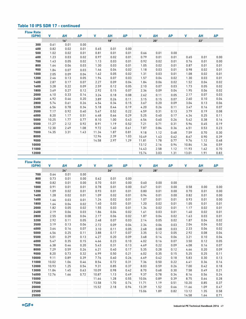
49Industrial PE Technical Handbook 2016
Table 10 IPS SDR 17 - continued Flow Rate
(GPM) V ΔH ΔP V ΔH ΔP V ΔH ΔP V ΔH ΔP16" 18" 20" 22"
300 0 .61 0 .01 0 .00 400 0 .82 0 .02 0 .01 0 .65 0 .01 0 .00 500 1 .02 0 .02 0 .01 0 .81 0 .01 0 .01 0 .66 0 .01 0 .00 600 1 .23 0 .03 0 .02 0 .97 0 .02 0 .01 0 .79 0 .01 0 .01 0 .65 0 .01 0 .00 700 1 .43 0 .05 0 .02 1 .13 0 .03 0 .01 0 .92 0 .02 0 .01 0 .76 0 .01 0 .00 800 1 .64 0 .06 0 .03 1 .30 0 .03 0 .01 1 .05 0 .02 0 .01 0 .87 0 .01 0 .01 900 1 .84 0 .07 0 .03 1 .46 0 .04 0 .02 1 .18 0 .03 0 .01 0 .98 0 .02 0 .01
1000 2 .05 0 .09 0 .04 1 .62 0 .05 0 .02 1 .31 0 .03 0 .01 1 .08 0 .02 0 .01 1200 2 .46 0 .13 0 .05 1 .94 0 .07 0 .03 1 .57 0 .04 0 .02 1 .30 0 .03 0 .01 1400 2 .87 0 .17 0 .07 2 .27 0 .09 0 .04 1 .84 0 .06 0 .02 1 .52 0 .04 0 .02 1600 3 .28 0 .22 0 .09 2 .59 0 .12 0 .05 2 .10 0 .07 0 .03 1 .73 0 .05 0 .02 1800 3 .69 0 .27 0 .12 2 .92 0 .15 0 .07 2 .36 0 .09 0 .04 1 .95 0 .06 0 .02 2000 4 .10 0 .33 0 .14 3 .24 0 .18 0 .08 2 .62 0 .11 0 .05 2 .17 0 .07 0 .03 2400 4 .92 0 .46 0 .20 3 .89 0 .26 0 .11 3 .15 0 .15 0 .07 2 .60 0 .10 0 .04 2800 5 .74 0 .61 0 .26 4 .54 0 .34 0 .15 3 .67 0 .20 0 .09 3 .04 0 .13 0 .06 3200 6 .56 0 .78 0 .34 5 .18 0 .44 0 .19 4 .20 0 .26 0 .11 3 .47 0 .16 0 .07 3500 7 .17 0 .92 0 .40 5 .67 0 .52 0 .22 4 .59 0 .31 0 .13 3 .79 0 .19 0 .08 4000 8 .20 1 .17 0 .51 6 .48 0 .66 0 .29 5 .25 0 .40 0 .17 4 .34 0 .25 0 .11 5000 10 .25 1 .77 0 .77 8 .10 1 .00 0 .43 6 .56 0 .60 0 .26 5 .42 0 .38 0 .16 5500 11 .27 2 .12 0 .92 8 .91 1 .19 0 .52 7 .21 0 .71 0 .31 5 .96 0 .45 0 .19 6000 12 .30 2 .49 1 .08 9 .72 1 .40 0 .61 7 .87 0 .84 0 .36 6 .51 0 .53 0 .23 7000 14 .35 3 .31 1 .43 11 .34 1 .87 0 .81 9 .18 1 .12 0 .48 7 .59 0 .70 0 .30 8000 12 .96 2 .39 1 .03 10 .49 1 .43 0 .62 8 .67 0 .90 0 .39 9000 14 .58 2 .97 1 .29 11 .81 1 .78 0 .77 9 .76 1 .12 0 .48
10000 13 .12 2 .16 0 .94 10 .84 1 .36 0 .59 11000 14 .43 2 .58 1 .12 11 .93 1 .62 0 .70 12000 15 .74 3 .03 1 .31 13 .01 1 .91 0 .83
Flow Rate (GPM) V ΔH ΔP V ΔH ΔP V ΔH ΔP V ΔH ΔP
24" 26" 28" 30"700 0 .64 0 .01 0 .00 800 0 .73 0 .01 0 .00 0 .62 0 .01 0 .00 900 0 .82 0 .01 0 .00 0 .70 0 .01 0 .00 0 .60 0 .00 0 .00
1000 0 .91 0 .01 0 .01 0 .78 0 .01 0 .00 0 .67 0 .01 0 .00 0 .58 0 .00 0 .00 1200 1 .09 0 .02 0 .01 0 .93 0 .01 0 .01 0 .80 0 .01 0 .00 0 .70 0 .01 0 .00 1400 1 .28 0 .02 0 .01 1 .09 0 .02 0 .01 0 .94 0 .01 0 .00 0 .82 0 .01 0 .00 1600 1 .46 0 .03 0 .01 1 .24 0 .02 0 .01 1 .07 0 .01 0 .01 0 .93 0 .01 0 .00 1800 1 .64 0 .04 0 .02 1 .40 0 .03 0 .01 1 .20 0 .02 0 .01 1 .05 0 .01 0 .01 2000 1 .82 0 .05 0 .02 1 .55 0 .03 0 .01 1 .34 0 .02 0 .01 1 .17 0 .02 0 .01 2400 2 .19 0 .06 0 .03 1 .86 0 .04 0 .02 1 .61 0 .03 0 .01 1 .40 0 .02 0 .01 2800 2 .55 0 .08 0 .04 2 .17 0 .06 0 .02 1 .87 0 .04 0 .02 1 .63 0 .03 0 .01 3200 2 .92 0 .11 0 .05 2 .48 0 .07 0 .03 2 .14 0 .05 0 .02 1 .87 0 .04 0 .02 3500 3 .19 0 .13 0 .06 2 .72 0 .09 0 .04 2 .34 0 .06 0 .03 2 .04 0 .04 0 .02 4000 3 .64 0 .16 0 .07 3 .10 0 .11 0 .05 2 .68 0 .08 0 .03 2 .33 0 .06 0 .02 5000 4 .56 0 .25 0 .11 3 .88 0 .17 0 .07 3 .35 0 .12 0 .05 2 .92 0 .08 0 .04 5500 5 .01 0 .29 0 .13 4 .27 0 .20 0 .09 3 .68 0 .14 0 .06 3 .21 0 .10 0 .04 6000 5 .47 0 .35 0 .15 4 .66 0 .23 0 .10 4 .02 0 .16 0 .07 3 .50 0 .12 0 .05 7000 6 .38 0 .46 0 .20 5 .43 0 .31 0 .13 4 .69 0 .22 0 .09 4 .08 0 .16 0 .07 8000 7 .29 0 .59 0 .26 6 .21 0 .40 0 .17 5 .35 0 .28 0 .12 4 .66 0 .20 0 .09 9000 8 .20 0 .73 0 .32 6 .99 0 .50 0 .21 6 .02 0 .35 0 .15 5 .25 0 .25 0 .11
10000 9 .11 0 .89 0 .39 7 .76 0 .60 0 .26 6 .69 0 .42 0 .18 5 .83 0 .30 0 .13 11000 10 .02 1 .06 0 .46 8 .54 0 .72 0 .31 7 .36 0 .50 0 .22 6 .41 0 .36 0 .16 12000 10 .93 1 .25 0 .54 9 .31 0 .85 0 .37 8 .03 0 .59 0 .26 7 .00 0 .42 0 .18 13000 11 .84 1 .45 0 .63 10 .09 0 .98 0 .42 8 .70 0 .68 0 .30 7 .58 0 .49 0 .21 14000 12 .76 1 .66 0 .72 10 .87 1 .13 0 .49 9 .37 0 .78 0 .34 8 .16 0 .56 0 .24 15000 11 .64 1 .28 0 .55 10 .04 0 .89 0 .39 8 .75 0 .64 0 .28 17500 13 .58 1 .70 0 .74 11 .71 1 .19 0 .51 10 .20 0 .85 0 .37 20000 15 .52 2 .18 0 .94 13 .39 1 .52 0 .66 11 .66 1 .09 0 .47 22500 15 .06 1 .89 0 .82 13 .12 1 .35 0 .58 25000 14 .58 1 .64 0 .71
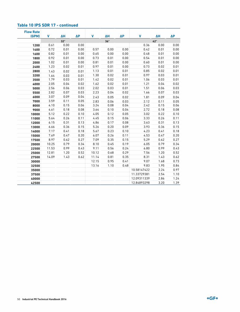
50 Industrial PE Technical Handbook 2016
Table 10 IPS SDR 17 - continued
Flow Rate (GPM) V ΔH ΔP V ΔH ΔP V ΔH ΔP
32" 36" 42"1200 0 .61 0 .00 0 .00 0 .36 0 .00 0 .00 1400 0 .72 0 .01 0 .00 0 .57 0 .00 0 .00 0 .42 0 .01 0 .00 1600 0 .82 0 .01 0 .00 0 .65 0 .00 0 .00 0 .48 0 .01 0 .00 1800 0 .92 0 .01 0 .00 0 .73 0 .01 0 .00 0 .54 0 .01 0 .00 2000 1 .02 0 .01 0 .00 0 .81 0 .01 0 .00 0 .60 0 .01 0 .00 2400 1 .23 0 .02 0 .01 0 .97 0 .01 0 .00 0 .73 0 .02 0 .01 2800 1 .43 0 .02 0 .01 1 .13 0 .01 0 .01 0 .85 0 .02 0 .01 3200 1 .64 0 .03 0 .01 1 .30 0 .02 0 .01 0 .97 0 .03 0 .01 3500 1 .79 0 .03 0 .01 1 .42 0 .02 0 .01 1 .06 0 .03 0 .01 4000 2 .05 0 .04 0 .02 1 .62 0 .02 0 .01 1 .21 0 .04 0 .02 5000 2 .56 0 .06 0 .03 2 .02 0 .03 0 .01 1 .51 0 .06 0 .03 5500 2 .82 0 .07 0 .03 2 .23 0 .04 0 .02 1 .66 0 .07 0 .03 6000 3 .07 0 .09 0 .04 2 .43 0 .05 0 .02 1 .81 0 .09 0 .04 7000 3 .59 0 .11 0 .05 2 .83 0 .06 0 .03 2 .12 0 .11 0 .05 8000 4 .10 0 .15 0 .06 3 .24 0 .08 0 .04 2 .42 0 .15 0 .06 9000 4 .61 0 .18 0 .08 3 .64 0 .10 0 .04 2 .72 0 .18 0 .08
10000 5 .12 0 .22 0 .10 4 .05 0 .12 0 .05 3 .02 0 .22 0 .10 11000 5 .64 0 .26 0 .11 4 .45 0 .15 0 .06 3 .33 0 .26 0 .11 12000 6 .15 0 .31 0 .13 4 .86 0 .17 0 .08 3 .63 0 .31 0 .13 13000 6 .66 0 .36 0 .15 5 .26 0 .20 0 .09 3 .93 0 .36 0 .15 14000 7 .17 0 .41 0 .18 5 .67 0 .23 0 .10 4 .23 0 .41 0 .18 15000 7 .69 0 .47 0 .20 6 .07 0 .26 0 .11 4 .53 0 .47 0 .20 17500 8 .97 0 .62 0 .27 7 .09 0 .35 0 .15 5 .29 0 .62 0 .27 20000 10 .25 0 .79 0 .34 8 .10 0 .45 0 .19 6 .05 0 .79 0 .34 22500 11 .53 0 .99 0 .43 9 .11 0 .56 0 .24 6 .80 0 .99 0 .43 25000 12 .81 1 .20 0 .52 10 .12 0 .68 0 .29 7 .56 1 .20 0 .52 27500 14 .09 1 .43 0 .62 11 .14 0 .81 0 .35 8 .31 1 .43 0 .62 30000 12 .15 0 .95 0 .41 9 .07 1 .68 0 .73 32500 13 .16 1 .10 0 .48 9 .83 1 .95 0 .84 35000 10 .58147422 2 .24 0 .97 37500 11 .33729381 2 .54 1 .10 40000 12 .09311339 2 .86 1 .24 42500 12 .84893298 3 .20 1 .39

51Industrial PE Technical Handbook 2016
Table 11 - Flow Rate vs. Friction Loss - DIPS DR 11Consult factory when flow rate exceeds 10 ft/sec
Flow Rate (GPM) V ΔH ΔP V ΔH ΔP
4" 6"30 0 .82 0 .07 0 .03 40 1 .09 0 .13 0 .05 50 1 .36 0 .19 0 .08 0 .66 0 .03 0 .01 60 1 .63 0 .26 0 .11 0 .79 0 .05 0 .02 70 1 .90 0 .35 0 .15 0 .92 0 .06 0 .03 80 2 .18 0 .45 0 .20 1 .05 0 .08 0 .03 90 2 .45 0 .56 0 .24 1 .18 0 .10 0 .04
100 2 .72 0 .68 0 .30 1 .32 0 .12 0 .05 125 3 .40 1 .03 0 .45 1 .65 0 .18 0 .08 150 4 .08 1 .45 0 .63 1 .97 0 .25 0 .11 175 4 .76 1 .92 0 .83 2 .30 0 .33 0 .14 200 5 .44 2 .46 1 .07 2 .63 0 .42 0 .18 250 6 .80 3 .72 1 .61 3 .29 0 .64 0 .28 300 8 .16 5 .22 2 .26 3 .95 0 .89 0 .39 350 9 .52 6 .94 3 .01 4 .61 1 .19 0 .51 400 10 .88 8 .89 3 .85 5 .27 1 .52 0 .66 450 12 .24 11 .06 4 .79 5 .92 1 .89 0 .82 500 13 .60 13 .44 5 .82 6 .58 2 .30 1 .00 550 7 .24 2 .74 1 .19 600 7 .90 3 .22 1 .40 700 9 .21 4 .29 1 .86 800 10 .53 5 .49 2 .38 900 11 .85 6 .83 2 .96
1000 13 .16 8 .31 3 .60
Flow Rate (GPM) V ΔH ΔP V ΔH ΔP
12" 14"200 0 .72 0 .02 0 .01 250 0 .90 0 .03 0 .01 0 .67 0 .01 0 .01 300 1 .08 0 .04 0 .02 0 .80 0 .02 0 .01 350 1 .26 0 .05 0 .02 0 .94 0 .02 0 .01 400 1 .44 0 .06 0 .03 1 .07 0 .03 0 .01 450 1 .62 0 .08 0 .03 1 .21 0 .04 0 .02 500 1 .80 0 .10 0 .04 1 .34 0 .05 0 .02 550 1 .98 0 .12 0 .05 1 .47 0 .06 0 .02 600 2 .16 0 .14 0 .06 1 .61 0 .07 0 .03 700 2 .52 0 .18 0 .08 1 .87 0 .09 0 .04 800 2 .88 0 .23 0 .10 2 .14 0 .11 0 .05 900 3 .24 0 .29 0 .13 2 .41 0 .14 0 .06
1000 3 .60 0 .35 0 .15 2 .68 0 .17 0 .07 1200 4 .32 0 .50 0 .21 3 .21 0 .24 0 .10 1400 5 .04 0 .66 0 .29 3 .75 0 .32 0 .14 1600 5 .76 0 .85 0 .37 4 .29 0 .41 0 .18 1800 6 .48 1 .05 0 .46 4 .82 0 .51 0 .22 2000 7 .20 1 .28 0 .55 5 .36 0 .62 0 .27 2400 8 .64 1 .79 0 .78 6 .43 0 .87 0 .38 2800 10 .07 2 .38 1 .03 7 .50 1 .16 0 .50 3200 11 .51 3 .05 1 .32 8 .57 1 .49 0 .64 3500 12 .59 3 .60 1 .56 9 .37 1 .76 0 .76 4000 10 .71 2 .25 0 .97 4500 12 .05 2 .80 1 .21 5000 13 .39 3 .40 1 .47
Flow Rate (GPM) V ΔH ΔP V ΔH ΔP
8" 10"100 0 .77 0 .03 0 .01 150 1 .15 0 .07 0 .03 0 .76 0 .02 0 .01 200 1 .53 0 .11 0 .05 1 .02 0 .04 0 .02 250 1 .91 0 .17 0 .07 1 .27 0 .06 0 .03 300 2 .30 0 .24 0 .10 1 .53 0 .09 0 .04 350 2 .68 0 .32 0 .14 1 .78 0 .12 0 .05 400 3 .06 0 .41 0 .18 2 .04 0 .15 0 .07 450 3 .45 0 .51 0 .22 2 .29 0 .19 0 .08 500 3 .83 0 .62 0 .27 2 .54 0 .23 0 .10 550 4 .21 0 .73 0 .32 2 .80 0 .27 0 .12 600 4 .59 0 .86 0 .37 3 .05 0 .32 0 .14 700 5 .36 1 .15 0 .50 3 .56 0 .42 0 .18 800 6 .12 1 .47 0 .64 4 .07 0 .54 0 .24 900 6 .89 1 .83 0 .79 4 .58 0 .68 0 .29
1000 7 .66 2 .22 0 .96 5 .09 0 .82 0 .36 1200 9 .19 3 .11 1 .35 6 .11 1 .15 0 .50 1400 10 .72 4 .14 1 .79 7 .12 1 .53 0 .66 1600 12 .25 5 .31 2 .30 8 .14 1 .96 0 .85 1800 13 .78 6 .60 2 .86 9 .16 2 .44 1 .06 2000 10 .18 2 .97 1 .28 2400 12 .21 4 .16 1 .80 2800 14 .25 5 .54 2 .40
Flow Rate (GPM) V ΔH ΔP V ΔH ΔP
16" 18"300 0 .62 0 .01 0 .00 400 0 .83 0 .02 0 .01 0 .66 0 .01 0 .00 500 1 .04 0 .03 0 .01 0 .82 0 .01 0 .01 600 1 .24 0 .04 0 .02 0 .99 0 .02 0 .01 700 1 .45 0 .05 0 .02 1 .15 0 .03 0 .01 800 1 .66 0 .06 0 .03 1 .32 0 .04 0 .02 900 1 .86 0 .08 0 .03 1 .48 0 .04 0 .02
1000 2 .07 0 .09 0 .04 1 .65 0 .05 0 .02 1200 2 .49 0 .13 0 .06 1 .98 0 .07 0 .03 1400 2 .90 0 .17 0 .07 2 .31 0 .10 0 .04 1600 3 .31 0 .22 0 .10 2 .64 0 .13 0 .05 1800 3 .73 0 .27 0 .12 2 .97 0 .16 0 .07 2000 4 .14 0 .33 0 .14 3 .30 0 .19 0 .08 2400 4 .97 0 .47 0 .20 3 .96 0 .27 0 .12 2800 5 .80 0 .62 0 .27 4 .62 0 .36 0 .15 3200 6 .63 0 .80 0 .34 5 .28 0 .46 0 .20 3500 7 .25 0 .94 0 .41 5 .77 0 .54 0 .23 4000 8 .28 1 .20 0 .52 6 .60 0 .69 0 .30 5000 10 .35 1 .82 0 .79 8 .24 1 .04 0 .45 5500 11 .39 2 .17 0 .94 9 .07 1 .25 0 .54 6000 12 .43 2 .55 1 .10 9 .89 1 .46 0 .63 7000 14 .50 3 .39 1 .47 11 .54 1 .95 0 .84 8000 13 .19 2 .49 1 .08 9000 14 .84 3 .10 1 .34
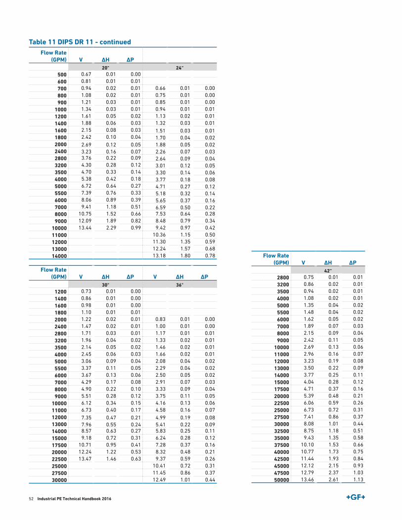
52 Industrial PE Technical Handbook 2016
Table 11 DIPS DR 11 - continued Flow Rate
(GPM) V ΔH ΔP20" 24“
500 0 .67 0 .01 0 .00 600 0 .81 0 .01 0 .01 700 0 .94 0 .02 0 .01 0 .66 0 .01 0 .00 800 1 .08 0 .02 0 .01 0 .75 0 .01 0 .00 900 1 .21 0 .03 0 .01 0 .85 0 .01 0 .00
1000 1 .34 0 .03 0 .01 0 .94 0 .01 0 .01 1200 1 .61 0 .05 0 .02 1 .13 0 .02 0 .01 1400 1 .88 0 .06 0 .03 1 .32 0 .03 0 .01 1600 2 .15 0 .08 0 .03 1 .51 0 .03 0 .01 1800 2 .42 0 .10 0 .04 1 .70 0 .04 0 .02 2000 2 .69 0 .12 0 .05 1 .88 0 .05 0 .02 2400 3 .23 0 .16 0 .07 2 .26 0 .07 0 .03 2800 3 .76 0 .22 0 .09 2 .64 0 .09 0 .04 3200 4 .30 0 .28 0 .12 3 .01 0 .12 0 .05 3500 4 .70 0 .33 0 .14 3 .30 0 .14 0 .06 4000 5 .38 0 .42 0 .18 3 .77 0 .18 0 .08 5000 6 .72 0 .64 0 .27 4 .71 0 .27 0 .12 5500 7 .39 0 .76 0 .33 5 .18 0 .32 0 .14 6000 8 .06 0 .89 0 .39 5 .65 0 .37 0 .16 7000 9 .41 1 .18 0 .51 6 .59 0 .50 0 .22 8000 10 .75 1 .52 0 .66 7 .53 0 .64 0 .28 9000 12 .09 1 .89 0 .82 8 .48 0 .79 0 .34
10000 13 .44 2 .29 0 .99 9 .42 0 .97 0 .42 11000 10 .36 1 .15 0 .50 12000 11 .30 1 .35 0 .59 13000 12 .24 1 .57 0 .68 14000 13 .18 1 .80 0 .78
Flow Rate (GPM) V ΔH ΔP V ΔH ΔP
30" 36"1200 0 .73 0 .01 0 .00 1400 0 .86 0 .01 0 .00 1600 0 .98 0 .01 0 .00 1800 1 .10 0 .01 0 .01 2000 1 .22 0 .02 0 .01 0 .83 0 .01 0 .00 2400 1 .47 0 .02 0 .01 1 .00 0 .01 0 .00 2800 1 .71 0 .03 0 .01 1 .17 0 .01 0 .01 3200 1 .96 0 .04 0 .02 1 .33 0 .02 0 .01 3500 2 .14 0 .05 0 .02 1 .46 0 .02 0 .01 4000 2 .45 0 .06 0 .03 1 .66 0 .02 0 .01 5000 3 .06 0 .09 0 .04 2 .08 0 .04 0 .02 5500 3 .37 0 .11 0 .05 2 .29 0 .04 0 .02 6000 3 .67 0 .13 0 .06 2 .50 0 .05 0 .02 7000 4 .29 0 .17 0 .08 2 .91 0 .07 0 .03 8000 4 .90 0 .22 0 .10 3 .33 0 .09 0 .04 9000 5 .51 0 .28 0 .12 3 .75 0 .11 0 .05
10000 6 .12 0 .34 0 .15 4 .16 0 .13 0 .06 11000 6 .73 0 .40 0 .17 4 .58 0 .16 0 .07 12000 7 .35 0 .47 0 .21 4 .99 0 .19 0 .08 13000 7 .96 0 .55 0 .24 5 .41 0 .22 0 .09 14000 8 .57 0 .63 0 .27 5 .83 0 .25 0 .11 15000 9 .18 0 .72 0 .31 6 .24 0 .28 0 .12 17500 10 .71 0 .95 0 .41 7 .28 0 .37 0 .16 20000 12 .24 1 .22 0 .53 8 .32 0 .48 0 .21 22500 13 .47 1 .46 0 .63 9 .37 0 .59 0 .26 25000 10 .41 0 .72 0 .31 27500 11 .45 0 .86 0 .37 30000 12 .49 1 .01 0 .44
Flow Rate (GPM) V ΔH ΔP
42“2800 0 .75 0 .01 0 .01 3200 0 .86 0 .02 0 .01 3500 0 .94 0 .02 0 .01 4000 1 .08 0 .02 0 .01 5000 1 .35 0 .04 0 .02 5500 1 .48 0 .04 0 .02 6000 1 .62 0 .05 0 .02 7000 1 .89 0 .07 0 .03 8000 2 .15 0 .09 0 .04 9000 2 .42 0 .11 0 .05
10000 2 .69 0 .13 0 .06 11000 2 .96 0 .16 0 .07 12000 3 .23 0 .19 0 .08 13000 3 .50 0 .22 0 .09 14000 3 .77 0 .25 0 .11 15000 4 .04 0 .28 0 .12 17500 4 .71 0 .37 0 .16 20000 5 .39 0 .48 0 .21 22500 6 .06 0 .59 0 .26 25000 6 .73 0 .72 0 .31 27500 7 .41 0 .86 0 .37 30000 8 .08 1 .01 0 .44 32500 8 .75 1 .18 0 .51 35000 9 .43 1 .35 0 .58 37500 10 .10 1 .53 0 .66 40000 10 .77 1 .73 0 .75 42500 11 .44 1 .93 0 .84 45000 12 .12 2 .15 0 .93 47500 12 .79 2 .37 1 .03 50000 13 .46 2 .61 1 .13
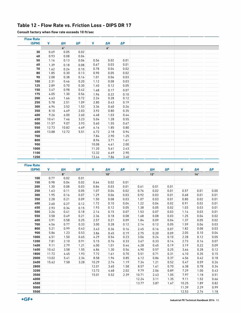
53Industrial PE Technical Handbook 2016
Table 12 - Flow Rate vs. Friction Loss - DIPS DR 17Consult factory when flow rate exceeds 10 ft/sec
Flow Rate (GPM) V ΔH ΔP V ΔH ΔP
4" 6"30 0 .69 0 .05 0 .02 40 0 .93 0 .08 0 .04 50 1 .16 0 .13 0 .06 0 .56 0 .02 0 .01 60 1 .39 0 .18 0 .08 0 .67 0 .03 0 .01 70 1 .62 0 .24 0 .10 0 .78 0 .04 0 .02 80 1 .85 0 .30 0 .13 0 .90 0 .05 0 .02 90 2 .08 0 .38 0 .16 1 .01 0 .06 0 .03
100 2 .31 0 .46 0 .20 1 .12 0 .08 0 .03 125 2 .89 0 .70 0 .30 1 .40 0 .12 0 .05 150 3 .47 0 .98 0 .42 1 .68 0 .17 0 .07 175 4 .05 1 .30 0 .56 1 .96 0 .22 0 .10 200 4 .63 1 .66 0 .72 2 .24 0 .28 0 .12 250 5 .78 2 .51 1 .09 2 .80 0 .43 0 .19 300 6 .94 3 .52 1 .53 3 .36 0 .60 0 .26 350 8 .10 4 .69 2 .03 3 .92 0 .80 0 .35 400 9 .26 6 .00 2 .60 4 .48 1 .03 0 .44 450 10 .41 7 .46 3 .23 5 .04 1 .28 0 .55 500 11 .57 9 .07 3 .93 5 .60 1 .55 0 .67 550 12 .73 10 .82 4 .69 6 .16 1 .85 0 .80 600 13 .88 12 .72 5 .51 6 .72 2 .18 0 .94 700 7 .84 2 .90 1 .25 800 8 .96 3 .71 1 .61 900 10 .08 4 .61 2 .00
1000 11 .20 5 .61 2 .43 1100 12 .32 6 .69 2 .90 1200 13 .44 7 .86 3 .40
Flow Rate (GPM) V ΔH ΔP V ΔH ΔP V ΔH ΔP V ΔH ΔP
8" 10" 12" 14"100 0 .77 0 .02 0 .01 150 0 .98 0 .04 0 .02 0 .64 0 .02 0 .01 200 1 .30 0 .08 0 .03 0 .86 0 .03 0 .01 0 .61 0 .01 0 .01 250 1 .63 0 .11 0 .05 1 .07 0 .04 0 .02 0 .76 0 .02 0 .01 0 .57 0 .01 0 .00 300 1 .95 0 .16 0 .07 1 .29 0 .06 0 .03 0 .92 0 .03 0 .01 0 .68 0 .01 0 .01 350 2 .28 0 .21 0 .09 1 .50 0 .08 0 .03 1 .07 0 .03 0 .01 0 .80 0 .02 0 .01 400 2 .60 0 .27 0 .12 1 .72 0 .10 0 .04 1 .22 0 .04 0 .02 0 .91 0 .02 0 .01 450 2 .93 0 .34 0 .15 1 .93 0 .12 0 .05 1 .38 0 .05 0 .02 1 .03 0 .03 0 .01 500 3 .26 0 .41 0 .18 2 .14 0 .15 0 .07 1 .53 0 .07 0 .03 1 .14 0 .03 0 .01 550 3 .58 0 .49 0 .21 2 .36 0 .18 0 .08 1 .68 0 .08 0 .03 1 .25 0 .04 0 .02 600 3 .91 0 .58 0 .25 2 .57 0 .21 0 .09 1 .84 0 .09 0 .04 1 .37 0 .05 0 .02 700 4 .56 0 .77 0 .33 3 .00 0 .28 0 .12 2 .14 0 .12 0 .05 1 .59 0 .06 0 .03 800 5 .21 0 .99 0 .43 3 .43 0 .36 0 .16 2 .45 0 .16 0 .07 1 .82 0 .08 0 .03 900 5 .86 1 .23 0 .53 3 .86 0 .45 0 .19 2 .75 0 .20 0 .09 2 .05 0 .10 0 .04
1000 6 .51 1 .50 0 .65 4 .29 0 .54 0 .23 3 .06 0 .24 0 .10 2 .28 0 .12 0 .05 1200 7 .81 2 .10 0 .91 5 .15 0 .76 0 .33 3 .67 0 .33 0 .14 2 .73 0 .16 0 .07 1400 9 .11 2 .79 1 .21 6 .00 1 .01 0 .44 4 .28 0 .45 0 .19 3 .19 0 .22 0 .09 1600 10 .42 3 .58 1 .55 6 .86 1 .30 0 .56 4 .90 0 .57 0 .25 3 .64 0 .28 0 .12 1800 11 .72 4 .45 1 .93 7 .72 1 .61 0 .70 5 .51 0 .71 0 .31 4 .10 0 .35 0 .15 2000 13 .02 5 .41 2 .34 8 .58 1 .96 0 .85 6 .12 0 .86 0 .37 4 .56 0 .42 0 .18 2400 15 .62 7 .58 3 .28 10 .29 2 .74 1 .19 7 .34 1 .21 0 .52 5 .47 0 .59 0 .26 2800 12 .01 3 .65 1 .58 8 .57 1 .61 0 .70 6 .38 0 .78 0 .34 3200 13 .72 4 .68 2 .02 9 .79 2 .06 0 .89 7 .29 1 .00 0 .43 3500 15 .01 5 .52 2 .39 10 .71 2 .43 1 .05 7 .97 1 .18 0 .51 4000 12 .24 3 .11 1 .35 9 .11 1 .52 0 .66 4500 13 .77 3 .87 1 .67 10 .25 1 .89 0 .82 5000 11 .39 2 .29 0 .99 5500 12 .53 2 .74 1 .18
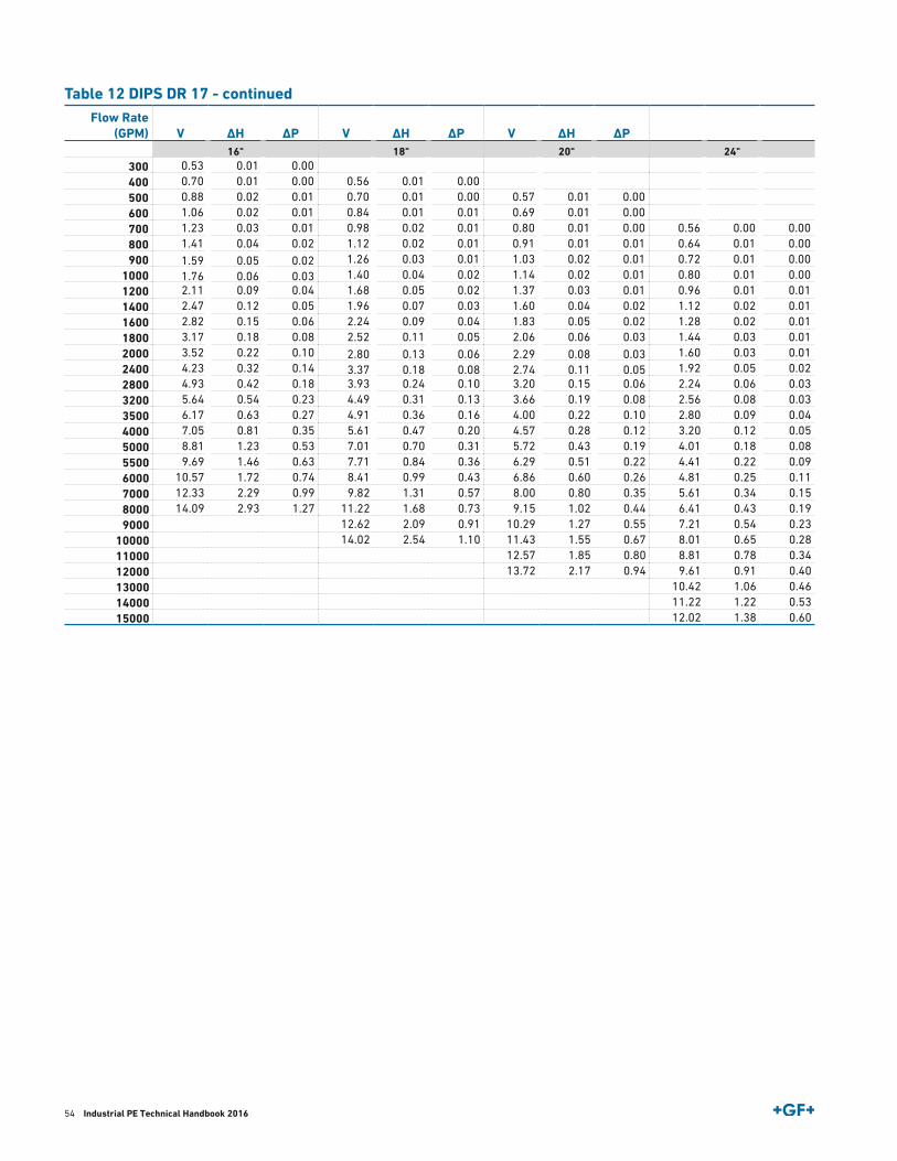
54 Industrial PE Technical Handbook 2016
Table 12 DIPS DR 17 - continued Flow Rate
(GPM) V ΔH ΔP V ΔH ΔP V ΔH ΔP16" 18" 20" 24"
300 0 .53 0 .01 0 .00 400 0 .70 0 .01 0 .00 0 .56 0 .01 0 .00 500 0 .88 0 .02 0 .01 0 .70 0 .01 0 .00 0 .57 0 .01 0 .00 600 1 .06 0 .02 0 .01 0 .84 0 .01 0 .01 0 .69 0 .01 0 .00 700 1 .23 0 .03 0 .01 0 .98 0 .02 0 .01 0 .80 0 .01 0 .00 0 .56 0 .00 0 .00 800 1 .41 0 .04 0 .02 1 .12 0 .02 0 .01 0 .91 0 .01 0 .01 0 .64 0 .01 0 .00 900 1 .59 0 .05 0 .02 1 .26 0 .03 0 .01 1 .03 0 .02 0 .01 0 .72 0 .01 0 .00
1000 1 .76 0 .06 0 .03 1 .40 0 .04 0 .02 1 .14 0 .02 0 .01 0 .80 0 .01 0 .00 1200 2 .11 0 .09 0 .04 1 .68 0 .05 0 .02 1 .37 0 .03 0 .01 0 .96 0 .01 0 .01 1400 2 .47 0 .12 0 .05 1 .96 0 .07 0 .03 1 .60 0 .04 0 .02 1 .12 0 .02 0 .01 1600 2 .82 0 .15 0 .06 2 .24 0 .09 0 .04 1 .83 0 .05 0 .02 1 .28 0 .02 0 .01 1800 3 .17 0 .18 0 .08 2 .52 0 .11 0 .05 2 .06 0 .06 0 .03 1 .44 0 .03 0 .01 2000 3 .52 0 .22 0 .10 2 .80 0 .13 0 .06 2 .29 0 .08 0 .03 1 .60 0 .03 0 .01 2400 4 .23 0 .32 0 .14 3 .37 0 .18 0 .08 2 .74 0 .11 0 .05 1 .92 0 .05 0 .02 2800 4 .93 0 .42 0 .18 3 .93 0 .24 0 .10 3 .20 0 .15 0 .06 2 .24 0 .06 0 .03 3200 5 .64 0 .54 0 .23 4 .49 0 .31 0 .13 3 .66 0 .19 0 .08 2 .56 0 .08 0 .03 3500 6 .17 0 .63 0 .27 4 .91 0 .36 0 .16 4 .00 0 .22 0 .10 2 .80 0 .09 0 .04 4000 7 .05 0 .81 0 .35 5 .61 0 .47 0 .20 4 .57 0 .28 0 .12 3 .20 0 .12 0 .05 5000 8 .81 1 .23 0 .53 7 .01 0 .70 0 .31 5 .72 0 .43 0 .19 4 .01 0 .18 0 .08 5500 9 .69 1 .46 0 .63 7 .71 0 .84 0 .36 6 .29 0 .51 0 .22 4 .41 0 .22 0 .09 6000 10 .57 1 .72 0 .74 8 .41 0 .99 0 .43 6 .86 0 .60 0 .26 4 .81 0 .25 0 .11 7000 12 .33 2 .29 0 .99 9 .82 1 .31 0 .57 8 .00 0 .80 0 .35 5 .61 0 .34 0 .15 8000 14 .09 2 .93 1 .27 11 .22 1 .68 0 .73 9 .15 1 .02 0 .44 6 .41 0 .43 0 .19 9000 12 .62 2 .09 0 .91 10 .29 1 .27 0 .55 7 .21 0 .54 0 .23
10000 14 .02 2 .54 1 .10 11 .43 1 .55 0 .67 8 .01 0 .65 0 .28 11000 12 .57 1 .85 0 .80 8 .81 0 .78 0 .34 12000 13 .72 2 .17 0 .94 9 .61 0 .91 0 .40 13000 10 .42 1 .06 0 .46 14000 11 .22 1 .22 0 .53 15000 12 .02 1 .38 0 .60
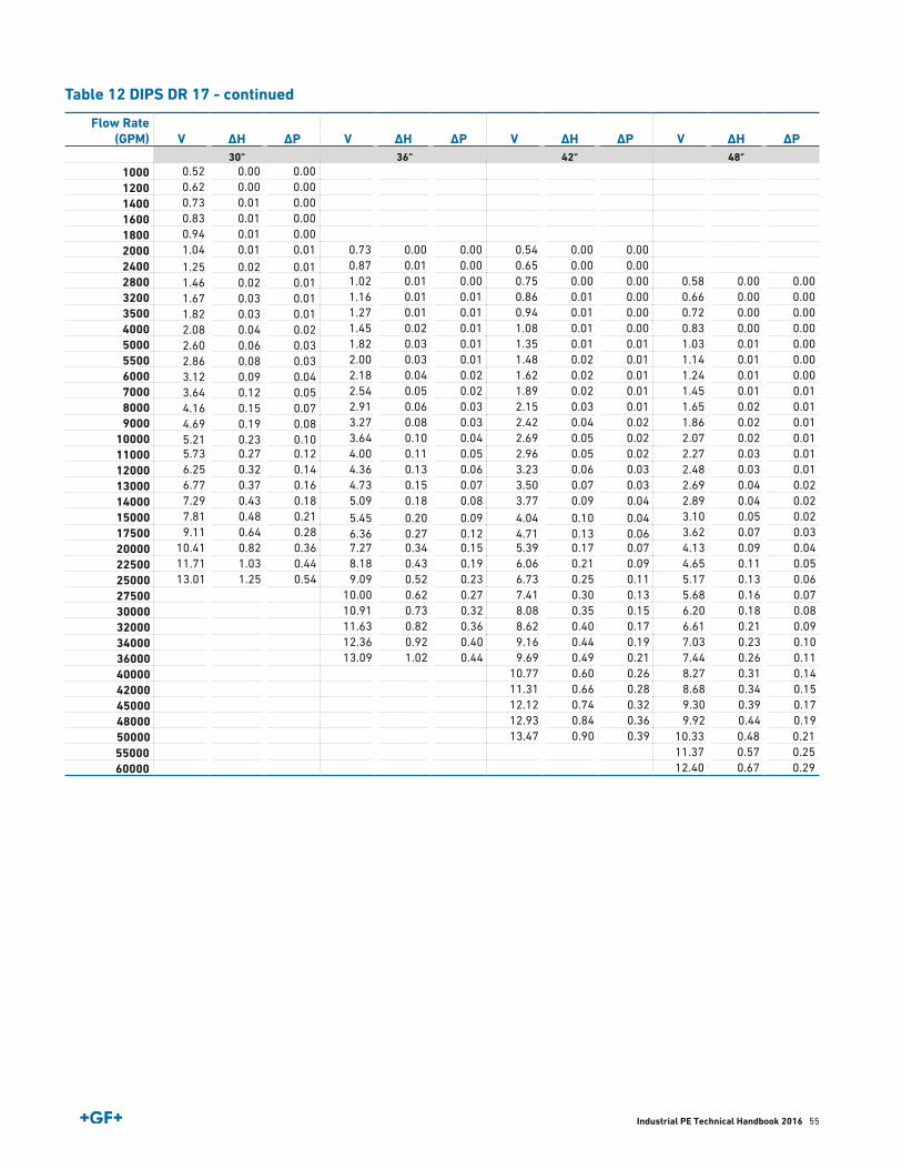
55Industrial PE Technical Handbook 2016
Table 12 DIPS DR 17 - continued
Flow Rate (GPM) V ΔH ΔP V ΔH ΔP V ΔH ΔP V ΔH ΔP
30" 36" 42" 48"1000 0 .52 0 .00 0 .00 1200 0 .62 0 .00 0 .00 1400 0 .73 0 .01 0 .00 1600 0 .83 0 .01 0 .00 1800 0 .94 0 .01 0 .00 2000 1 .04 0 .01 0 .01 0 .73 0 .00 0 .00 0 .54 0 .00 0 .00 2400 1 .25 0 .02 0 .01 0 .87 0 .01 0 .00 0 .65 0 .00 0 .00 2800 1 .46 0 .02 0 .01 1 .02 0 .01 0 .00 0 .75 0 .00 0 .00 0 .58 0 .00 0 .00 3200 1 .67 0 .03 0 .01 1 .16 0 .01 0 .01 0 .86 0 .01 0 .00 0 .66 0 .00 0 .00 3500 1 .82 0 .03 0 .01 1 .27 0 .01 0 .01 0 .94 0 .01 0 .00 0 .72 0 .00 0 .00 4000 2 .08 0 .04 0 .02 1 .45 0 .02 0 .01 1 .08 0 .01 0 .00 0 .83 0 .00 0 .00 5000 2 .60 0 .06 0 .03 1 .82 0 .03 0 .01 1 .35 0 .01 0 .01 1 .03 0 .01 0 .00 5500 2 .86 0 .08 0 .03 2 .00 0 .03 0 .01 1 .48 0 .02 0 .01 1 .14 0 .01 0 .00 6000 3 .12 0 .09 0 .04 2 .18 0 .04 0 .02 1 .62 0 .02 0 .01 1 .24 0 .01 0 .00 7000 3 .64 0 .12 0 .05 2 .54 0 .05 0 .02 1 .89 0 .02 0 .01 1 .45 0 .01 0 .01 8000 4 .16 0 .15 0 .07 2 .91 0 .06 0 .03 2 .15 0 .03 0 .01 1 .65 0 .02 0 .01 9000 4 .69 0 .19 0 .08 3 .27 0 .08 0 .03 2 .42 0 .04 0 .02 1 .86 0 .02 0 .01
10000 5 .21 0 .23 0 .10 3 .64 0 .10 0 .04 2 .69 0 .05 0 .02 2 .07 0 .02 0 .01 11000 5 .73 0 .27 0 .12 4 .00 0 .11 0 .05 2 .96 0 .05 0 .02 2 .27 0 .03 0 .01 12000 6 .25 0 .32 0 .14 4 .36 0 .13 0 .06 3 .23 0 .06 0 .03 2 .48 0 .03 0 .01 13000 6 .77 0 .37 0 .16 4 .73 0 .15 0 .07 3 .50 0 .07 0 .03 2 .69 0 .04 0 .02 14000 7 .29 0 .43 0 .18 5 .09 0 .18 0 .08 3 .77 0 .09 0 .04 2 .89 0 .04 0 .02 15000 7 .81 0 .48 0 .21 5 .45 0 .20 0 .09 4 .04 0 .10 0 .04 3 .10 0 .05 0 .02 17500 9 .11 0 .64 0 .28 6 .36 0 .27 0 .12 4 .71 0 .13 0 .06 3 .62 0 .07 0 .03 20000 10 .41 0 .82 0 .36 7 .27 0 .34 0 .15 5 .39 0 .17 0 .07 4 .13 0 .09 0 .04 22500 11 .71 1 .03 0 .44 8 .18 0 .43 0 .19 6 .06 0 .21 0 .09 4 .65 0 .11 0 .05 25000 13 .01 1 .25 0 .54 9 .09 0 .52 0 .23 6 .73 0 .25 0 .11 5 .17 0 .13 0 .06 27500 10 .00 0 .62 0 .27 7 .41 0 .30 0 .13 5 .68 0 .16 0 .07 30000 10 .91 0 .73 0 .32 8 .08 0 .35 0 .15 6 .20 0 .18 0 .08 32000 11 .63 0 .82 0 .36 8 .62 0 .40 0 .17 6 .61 0 .21 0 .09 34000 12 .36 0 .92 0 .40 9 .16 0 .44 0 .19 7 .03 0 .23 0 .10 36000 13 .09 1 .02 0 .44 9 .69 0 .49 0 .21 7 .44 0 .26 0 .11 40000 10 .77 0 .60 0 .26 8 .27 0 .31 0 .14 42000 11 .31 0 .66 0 .28 8 .68 0 .34 0 .15 45000 12 .12 0 .74 0 .32 9 .30 0 .39 0 .17 48000 12 .93 0 .84 0 .36 9 .92 0 .44 0 .19 50000 13 .47 0 .90 0 .39 10 .33 0 .48 0 .21 55000 11 .37 0 .57 0 .25 60000 12 .40 0 .67 0 .29
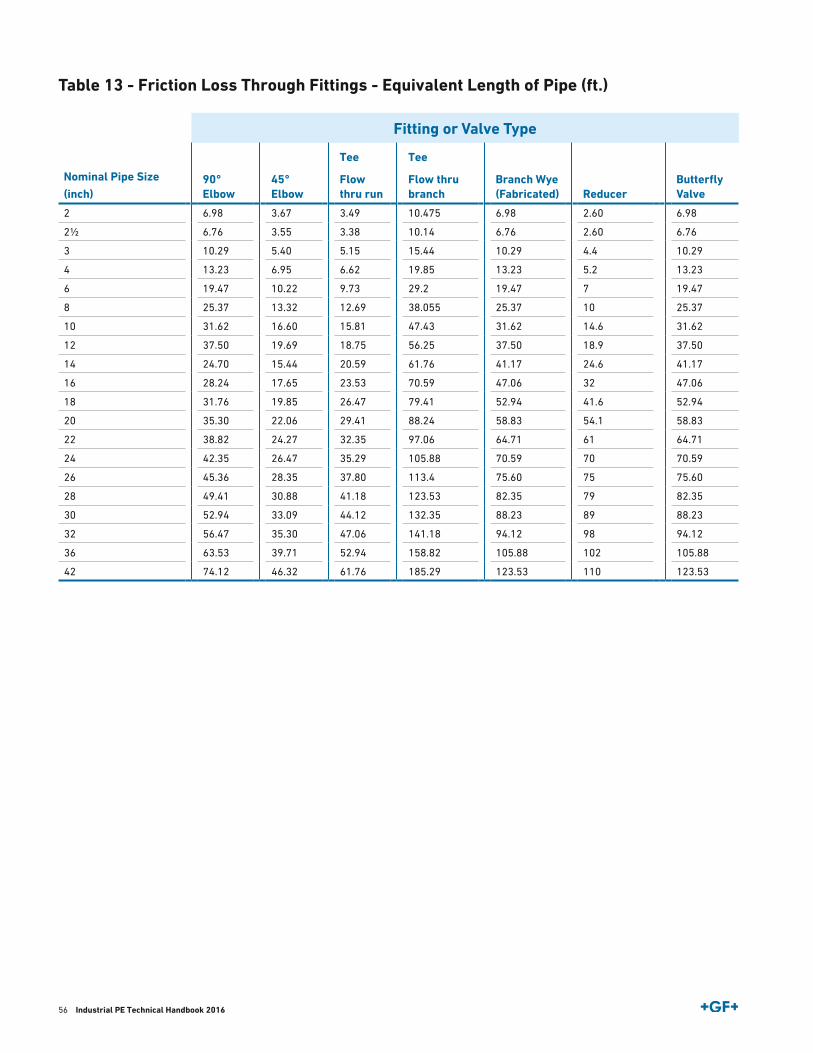
56 Industrial PE Technical Handbook 2016
Table 13 - Friction Loss Through Fittings - Equivalent Length of Pipe (ft.)
Fitting or Valve Type
Nominal Pipe Size (inch)
90° Elbow
45° Elbow
Tee
Flow thru run
Tee
Flow thru branch
Branch Wye (Fabricated) Reducer
Butterfly Valve
2 6 .98 3 .67 3 .49 10 .475 6 .98 2 .60 6 .98
2½ 6 .76 3 .55 3 .38 10 .14 6 .76 2 .60 6 .76
3 10 .29 5 .40 5 .15 15 .44 10 .29 4 .4 10 .29
4 13 .23 6 .95 6 .62 19 .85 13 .23 5 .2 13 .23
6 19 .47 10 .22 9 .73 29 .2 19 .47 7 19 .47
8 25 .37 13 .32 12 .69 38 .055 25 .37 10 25 .37
10 31 .62 16 .60 15 .81 47 .43 31 .62 14 .6 31 .62
12 37 .50 19 .69 18 .75 56 .25 37 .50 18 .9 37 .50
14 24 .70 15 .44 20 .59 61 .76 41 .17 24 .6 41 .17
16 28 .24 17 .65 23 .53 70 .59 47 .06 32 47 .06
18 31 .76 19 .85 26 .47 79 .41 52 .94 41 .6 52 .94
20 35 .30 22 .06 29 .41 88 .24 58 .83 54 .1 58 .83
22 38 .82 24 .27 32 .35 97 .06 64 .71 61 64 .71
24 42 .35 26 .47 35 .29 105 .88 70 .59 70 70 .59
26 45 .36 28 .35 37 .80 113 .4 75 .60 75 75 .60
28 49 .41 30 .88 41 .18 123 .53 82 .35 79 82 .35
30 52 .94 33 .09 44 .12 132 .35 88 .23 89 88 .23
32 56 .47 35 .30 47 .06 141 .18 94 .12 98 94 .12
36 63 .53 39 .71 52 .94 158 .82 105 .88 102 105 .88
42 74 .12 46 .32 61 .76 185 .29 123 .53 110 123 .53
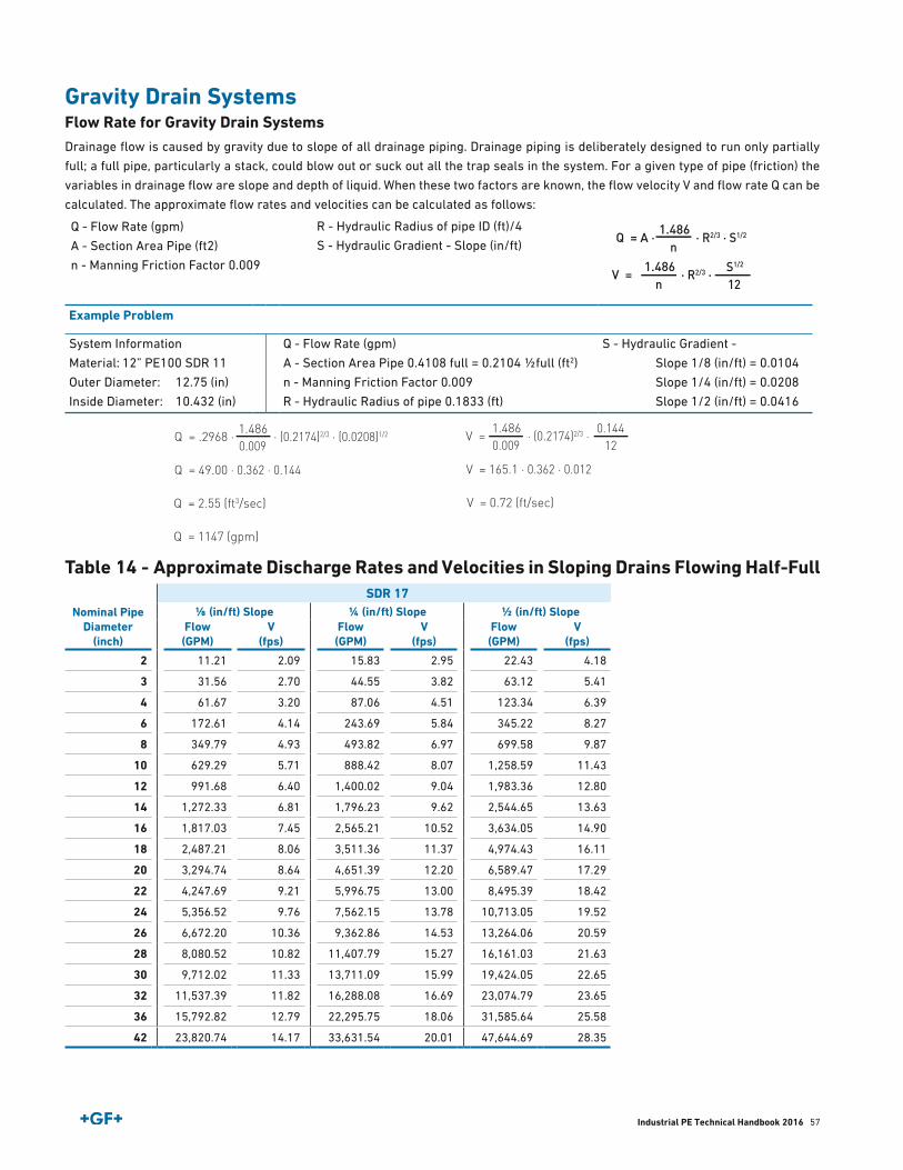
57Industrial PE Technical Handbook 2016
Gravity Drain SystemsFlow Rate for Gravity Drain SystemsDrainage flow is caused by gravity due to slope of all drainage piping . Drainage piping is deliberately designed to run only partially
full; a full pipe, particularly a stack, could blow out or suck out all the trap seals in the system . For a given type of pipe (friction) the
variables in drainage flow are slope and depth of liquid . When these two factors are known, the flow velocity V and flow rate Q can be
calculated . The approximate flow rates and velocities can be calculated as follows:
Q - Flow Rate (gpm)
A - Section Area Pipe (ft2)
n - Manning Friction Factor 0 .009
R - Hydraulic Radius of pipe ID (ft)/4
S - Hydraulic Gradient - Slope (in/ft)Q = A · · R2/3 · S1/21.486
n
FORMULA
Q = .2968 · · (0.2174)2/3 · (0.0208)1/21.4860.009
Q = 49.00 · 0.362 · 0.144 Q = 2.55 (ft3/sec) Q = 1147 (gpm)
V = · R2/3 ·
FORMULA
1.486n
V = · (0.2174)2/3 · 1.4860.009
V = 165.1 · 0.362 · 0.012 V = 0.72 (ft/sec)S1/2
120.144
12
Q = A · · R2/3 · S1/21.486n
FORMULA
Q = .2968 · · (0.2174)2/3 · (0.0208)1/21.4860.009
Q = 49.00 · 0.362 · 0.144 Q = 2.55 (ft3/sec) Q = 1147 (gpm)
V = · R2/3 ·
FORMULA
1.486n
V = · (0.2174)2/3 · 1.4860.009
V = 165.1 · 0.362 · 0.012 V = 0.72 (ft/sec)S1/2
120.144
12
Example Problem
System Information
Material: 12” PE100 SDR 11
Outer Diameter: 12 .75 (in)
Inside Diameter: 10 .432 (in)
Q - Flow Rate (gpm)
A - Section Area Pipe 0 .4108 full = 0 .2104 ½full (ft2)
n - Manning Friction Factor 0 .009
R - Hydraulic Radius of pipe 0 .1833 (ft)
S - Hydraulic Gradient -
Slope 1/8 (in/ft) = 0 .0104
Slope 1/4 (in/ft) = 0 .0208
Slope 1/2 (in/ft) = 0 .0416
Q = A · · R2/3 · S1/21.486n
FORMULA
Q = .2968 · · (0.2174)2/3 · (0.0208)1/21.4860.009
Q = 49.00 · 0.362 · 0.144 Q = 2.55 (ft3/sec) Q = 1147 (gpm)
V = · R2/3 ·
FORMULA
1.486n
V = · (0.2174)2/3 · 1.4860.009
V = 165.1 · 0.362 · 0.012 V = 0.72 (ft/sec)S1/2
120.144
12
Q = A · · R2/3 · S1/21.486n
FORMULA
Q = .2968 · · (0.2174)2/3 · (0.0208)1/21.4860.009
Q = 49.00 · 0.362 · 0.144 Q = 2.55 (ft3/sec) Q = 1147 (gpm)
V = · R2/3 ·
FORMULA
1.486n
V = · (0.2174)2/3 · 1.4860.009
V = 165.1 · 0.362 · 0.012 V = 0.72 (ft/sec)S1/2
120.144
12
Q = A · · R2/3 · S1/21.486n
FORMULA
Q = .2968 · · (0.2174)2/3 · (0.0208)1/21.4860.009
Q = 49.00 · 0.362 · 0.144 Q = 2.55 (ft3/sec) Q = 1147 (gpm)
V = · R2/3 ·
FORMULA
1.486n
V = · (0.2174)2/3 · 1.4860.009
V = 165.1 · 0.362 · 0.012 V = 0.72 (ft/sec)S1/2
120.144
12
Q = A · · R2/3 · S1/21.486n
FORMULA
Q = .2968 · · (0.2174)2/3 · (0.0208)1/21.4860.009
Q = 49.00 · 0.362 · 0.144 Q = 2.55 (ft3/sec) Q = 1147 (gpm)
V = · R2/3 ·
FORMULA
1.486n
V = · (0.2174)2/3 · 1.4860.009
V = 165.1 · 0.362 · 0.012 V = 0.72 (ft/sec)S1/2
120.144
12
Q = A · · R2/3 · S1/21.486n
FORMULA
Q = .2968 · · (0.2174)2/3 · (0.0208)1/21.4860.009
Q = 49.00 · 0.362 · 0.144 Q = 2.55 (ft3/sec) Q = 1147 (gpm)
V = · R2/3 ·
FORMULA
1.486n
V = · (0.2174)2/3 · 1.4860.009
V = 165.1 · 0.362 · 0.012 V = 0.72 (ft/sec)S1/2
120.144
12
Q = A · · R2/3 · S1/21.486n
FORMULA
Q = .2968 · · (0.2174)2/3 · (0.0208)1/21.4860.009
Q = 49.00 · 0.362 · 0.144 Q = 2.55 (ft3/sec) Q = 1147 (gpm)
V = · R2/3 ·
FORMULA
1.486n
V = · (0.2174)2/3 · 1.4860.009
V = 165.1 · 0.362 · 0.012 V = 0.72 (ft/sec)S1/2
120.144
12
Q = A · · R2/3 · S1/21.486n
FORMULA
Q = .2968 · · (0.2174)2/3 · (0.0208)1/21.4860.009
Q = 49.00 · 0.362 · 0.144 Q = 2.55 (ft3/sec) Q = 1147 (gpm)
V = · R2/3 ·
FORMULA
1.486n
V = · (0.2174)2/3 · 1.4860.009
V = 165.1 · 0.362 · 0.012 V = 0.72 (ft/sec)S1/2
120.144
12
Table 14 - Approximate Discharge Rates and Velocities in Sloping Drains Flowing Half-FullSDR 17
Nominal Pipe Diameter
(inch)
⅛ (in/ft) Slope ¼ (in/ft) Slope ½ (in/ft) SlopeFlow
(GPM)V
(fps)Flow
(GPM)V
(fps)Flow
(GPM)V
(fps)
2 11 .21 2 .09 15 .83 2 .95 22 .43 4 .18
3 31 .56 2 .70 44 .55 3 .82 63 .12 5 .41
4 61 .67 3 .20 87 .06 4 .51 123 .34 6 .39
6 172 .61 4 .14 243 .69 5 .84 345 .22 8 .27
8 349 .79 4 .93 493 .82 6 .97 699 .58 9 .87
10 629 .29 5 .71 888 .42 8 .07 1,258 .59 11 .43
12 991 .68 6 .40 1,400 .02 9 .04 1,983 .36 12 .80
14 1,272 .33 6 .81 1,796 .23 9 .62 2,544 .65 13 .63
16 1,817 .03 7 .45 2,565 .21 10 .52 3,634 .05 14 .90
18 2,487 .21 8 .06 3,511 .36 11 .37 4,974 .43 16 .11
20 3,294 .74 8 .64 4,651 .39 12 .20 6,589 .47 17 .29
22 4,247 .69 9 .21 5,996 .75 13 .00 8,495 .39 18 .42
24 5,356 .52 9 .76 7,562 .15 13 .78 10,713 .05 19 .52
26 6,672 .20 10 .36 9,362 .86 14 .53 13,264 .06 20 .59
28 8,080 .52 10 .82 11,407 .79 15 .27 16,161 .03 21 .63
30 9,712 .02 11 .33 13,711 .09 15 .99 19,424 .05 22 .65
32 11,537 .39 11 .82 16,288 .08 16 .69 23,074 .79 23 .65
36 15,792 .82 12 .79 22,295 .75 18 .06 31,585 .64 25 .58
42 23,820 .74 14 .17 33,631 .54 20 .01 47,644 .69 28 .35
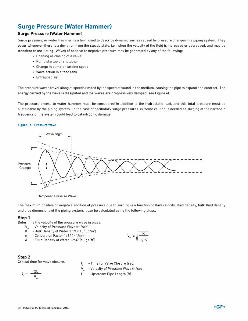
58 Industrial PE Technical Handbook 2016
Surge Pressure (Water Hammer)Surge Pressure (Water Hammer)Surge pressure, or water hammer, is a term used to describe dynamic surges caused by pressure changes in a piping system . They
occur whenever there is a deviation from the steady state, i .e .; when the velocity of the fluid is increased or decreased, and may be
transient or oscillating . Waves of positive or negative pressure may be generated by any of the following:
• Opening or closing of a valve
• Pump startup or shutdown
• Change in pump or turbine speed
• Wave action in a feed tank
• Entrapped air
The pressure waves travel along at speeds limited by the speed of sound in the medium, causing the pipe to expand and contract . The
energy carried by the wave is dissipated and the waves are progressively damped (see Figure 6) .
The pressure excess to water hammer must be considered in addition to the hydrostatic load, and this total pressure must be
sustainable by the piping system . In the case of oscillatory surge pressures, extreme caution is needed as surging at the harmonic
frequency of the system could lead to catastrophic damage .
Figure 16 - Pressure Wave
PressureChange
Wavelength
Dampened Pressure Wave
The maximum positive or negative addition of pressure due to surging is a function of fluid velocity, fluid density, bulk fluid density
and pipe dimensions of the piping system . It can be calculated using the following steps .
Step 1Determine the velocity of the pressure wave in pipes . V
w - Velocity of Pressure Wave (ft ./sec)
K - Bulk Density of Water 3 .19 x 105 (lb/in2) n
i - Conversion Factor 1/144 (ft2/in2)
δ - Fluid Density of Water 1 .937 (slugs/ft3)Vw =
K
ni · δ √ 3.19 x 105
· 1.937 √ 1144
Vw = Vw = 4870 (ft/sec)
STEP 1:
STEP 2:
STEP 3:
tc =2LVw
Pg =2 · δ · L · V · ni
tv
tc =2 · 5004870
tc = 0.2 (sec)
Pi = δ · V · Vw ni Pi =1.937 · 4 · 4870
144Pi = 262 (lb/in2)
STEP 4:
STEP 5:
Pmax = Pi + Ps Pmax = 262 + 50 Pmax = 312 (lb/in2)
Pg =2 · 1.937 · 500 · 4 ·
2Pg = 26.9 (lb/in2)
1144
Pmax = Pg + Ps Pmax = 26.9 + 50 = 76.9 (lb/in2)
Step 2Critical time for valve closure .
Vw =K
ni · δ √ 3.19 x 105
· 1.937 √ 1144
Vw = Vw = 4870 (ft/sec)
STEP 1:
STEP 2:
STEP 3:
tc =2LVw
Pg =2 · δ · L · V · ni
tv
tc =2 · 5004870
tc = 0.2 (sec)
Pi = δ · V · Vw ni Pi =1.937 · 4 · 4870
144Pi = 262 (lb/in2)
STEP 4:
STEP 5:
Pmax = Pi + Ps Pmax = 262 + 50 Pmax = 312 (lb/in2)
Pg =2 · 1.937 · 500 · 4 ·
2Pg = 26.9 (lb/in2)
1144
Pmax = Pg + Ps Pmax = 26.9 + 50 = 76.9 (lb/in2)
tc - Time for Valve Closure (sec)
Vw - Velocity of Pressure Wave (ft/sec)
L - Upstream Pipe Length (ft)
59Industrial PE Technical Handbook 2016
Step 3Maximum pressure increase; assume valve closure
time is less than the critical closure time and fluid
velocity goes to 0 .
Vw =K
ni · δ √ 3.19 x 105
· 1.937 √ 1144
Vw = Vw = 4870 (ft/sec)
STEP 1:
STEP 2:
STEP 3:
tc =2LVw
Pg =2 · δ · L · V · ni
tv
tc =2 · 5004870
tc = 0.2 (sec)
Pi = δ · V · Vw ni Pi =1.937 · 4 · 4870
144Pi = 262 (lb/in2)
STEP 4:
STEP 5:
Pmax = Pi + Ps Pmax = 262 + 50 Pmax = 312 (lb/in2)
Pg =2 · 1.937 · 500 · 4 ·
2Pg = 26.9 (lb/in2)
1144
Pmax = Pg + Ps Pmax = 26.9 + 50 = 76.9 (lb/in2)
Pi - Maximum Total Pressure (lb/in2)
δ - Fluid Density (slugs/ft3)
V - Fluid Velocity (ft/sec)
Vw - Velocity of Pressure Wave
ni - Conversion Factor 1/144 (ft2/in2)
Special Consideration
Calculate the Maximum Instantaneous System Pressure .
Vw =K
ni · δ √ 3.19 x 105
· 1.937 √ 1144
Vw = Vw = 4870 (ft/sec)
STEP 1:
STEP 2:
STEP 3:
tc =2LVw
Pg =2 · δ · L · V · ni
tv
tc =2 · 5004870
tc = 0.2 (sec)
Pi = δ · V · Vw ni Pi =1.937 · 4 · 4870
144Pi = 262 (lb/in2)
STEP 4:
STEP 5:
Pmax = Pi + Ps Pmax = 262 + 50 Pmax = 312 (lb/in2)
Pg =2 · 1.937 · 500 · 4 ·
2Pg = 26.9 (lb/in2)
1144
Pmax = Pg + Ps Pmax = 26.9 + 50 = 76.9 (lb/in2)
Pmax
- Maximum System Operating Pressure (lb/in2)
Pi - Maximum Pressure Increase (lb/in2)
Ps - Standard System Operating Pressure (lb/in2)
Cautionary Note
Caution is recommended if Pmax
is greater than the maximum
system design pressure multiplied by a design factor of 2x .
Example: Pipe is rated at 200 psi . If Pmax
exceeds 400psi
(200psi×2 safety factor), then precaution must be implemented
in case of maximum pressure wave (i .e . water hammer) to
prevent possible pipe failure .
Step 4Determine the Maximum System Pressure Increase with
Gradual Valve Closure
Pg - Gradual Pressure Increase with Valve Closure (lb/in2)
L - Upstream Pipe Length (ft .)
V - Fluid Velocity (ft ./sec)
ni - Conversion Factor 1/144 (ft2/in2)
tv - Time of Valve Closure (sec)
Vw =K
ni · δ √ 3.19 x 105
· 1.937 √ 1144
Vw = Vw = 4870 (ft/sec)
STEP 1:
STEP 2:
STEP 3:
tc =2LVw
Pg =2 · δ · L · V · ni
tv
tc =2 · 5004870
tc = 0.2 (sec)
Pi = δ · V · Vw ni Pi =1.937 · 4 · 4870
144Pi = 262 (lb/in2)
STEP 4:
STEP 5:
Pmax = Pi + Ps Pmax = 262 + 50 Pmax = 312 (lb/in2)
Pg =2 · 1.937 · 500 · 4 ·
2Pg = 26.9 (lb/in2)
1144
Pmax = Pg + Ps Pmax = 26.9 + 50 = 76.9 (lb/in2)
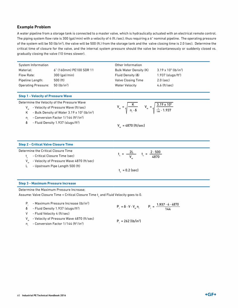
60 Industrial PE Technical Handbook 2016
Example ProblemA water pipeline from a storage tank is connected to a master valve, which is hydraulically actuated with an electrical remote control .
The piping system flow rate is 300 (gal/min) with a velocity of 4 (ft ./sec); thus requiring a 6“ nominal pipeline . The operating pressure
of the system will be 50 (lb/in2), the valve will be 500 (ft .) from the storage tank and the valve closing time is 2 .0 (sec) . Determine the
critical time of closure for the valve, and the internal system pressure should the valve be instantaneously or suddenly closed vs .
gradually closing the valve (10 times slower) .
System Information
Material: 6” (160mm) PE100 SDR 11
Flow Rate: 300 (gal/min)
Pipeline Length: 500 (ft)
Operating Pressure: 50 (lb/in2)
Other Information
Bulk Water Density (K) 3 .19 x 105 (lb/in2)
Fluid Density (δ) 1 .937 (slugs/ft3)
Valve Closing Time 2 .0 (sec)
Water Velocity 4 .6 (ft/sec)
Step 1 - Velocity of Pressure Wave
Determine the Velocity of the Pressure Wave
Vw - Velocity of Pressure Wave (ft/sec)
K - Bulk Density of Water 3 .19 x 105 (lb/in2)
ni - Conversion Factor 1/144 (ft2/in2)
δ - Fluid Density 1 .937 (slugs/ft3)
Vw =K
ni · δ √ 3.19 x 105
· 1.937 √ 1144
Vw = Vw = 4870 (ft/sec)
STEP 1:
STEP 2:
STEP 3:
tc =2LVw
Pg =2 · δ · L · V · ni
tv
tc =2 · 5004870
tc = 0.2 (sec)
Pi = δ · V · Vw ni Pi =1.937 · 4 · 4870
144Pi = 262 (lb/in2)
STEP 4:
STEP 5:
Pmax = Pi + Ps Pmax = 262 + 50 Pmax = 312 (lb/in2)
Pg =2 · 1.937 · 500 · 4 ·
2Pg = 26.9 (lb/in2)
1144
Pmax = Pg + Ps Pmax = 26.9 + 50 = 76.9 (lb/in2)
Step 2 - Critical Valve Closure Time
Determine the Critical Closure Time
tc - Critical Closure Time (sec)
Vw - Velocity of Pressure Wave 4870 (ft/sec)
L - Upstream Pipe Length 500 (ft)
Vw =K
ni · δ √ 3.19 x 105
· 1.937 √ 1144
Vw = Vw = 4870 (ft/sec)
STEP 1:
STEP 2:
STEP 3:
tc =2LVw
Pg =2 · δ · L · V · ni
tv
tc =2 · 5004870
tc = 0.2 (sec)
Pi = δ · V · Vw ni Pi =1.937 · 4 · 4870
144Pi = 262 (lb/in2)
STEP 4:
STEP 5:
Pmax = Pi + Ps Pmax = 262 + 50 Pmax = 312 (lb/in2)
Pg =2 · 1.937 · 500 · 4 ·
2Pg = 26.9 (lb/in2)
1144
Pmax = Pg + Ps Pmax = 26.9 + 50 = 76.9 (lb/in2)
Step 3 - Maximum Pressure Increase
Determine the Maximum Pressure Increase;
Assume: Valve Closure Time < Critical Closure Time tc and Fluid Velocity goes to 0 .
Pi - Maximum Pressure Increase (lb/in2)
δ - Fluid Density 1 .937 (slugs/ft3)
V - Fluid Velocity 4 (ft/sec)
Vw - Velocity of Pressure Wave 4870 (ft/sec)
ni - Conversion Factor 1/144 (ft2/in2)
Vw =K
ni · δ √ 3.19 x 105
· 1.937 √ 1144
Vw = Vw = 4870 (ft/sec)
STEP 1:
STEP 2:
STEP 3:
tc =2LVw
Pg =2 · δ · L · V · ni
tv
tc =2 · 5004870
tc = 0.2 (sec)
Pi = δ · V · Vw ni Pi =1.937 · 4 · 4870
144Pi = 262 (lb/in2)
STEP 4:
STEP 5:
Pmax = Pi + Ps Pmax = 262 + 50 Pmax = 312 (lb/in2)
Pg =2 · 1.937 · 500 · 4 ·
2Pg = 26.9 (lb/in2)
1144
Pmax = Pg + Ps Pmax = 26.9 + 50 = 76.9 (lb/in2)
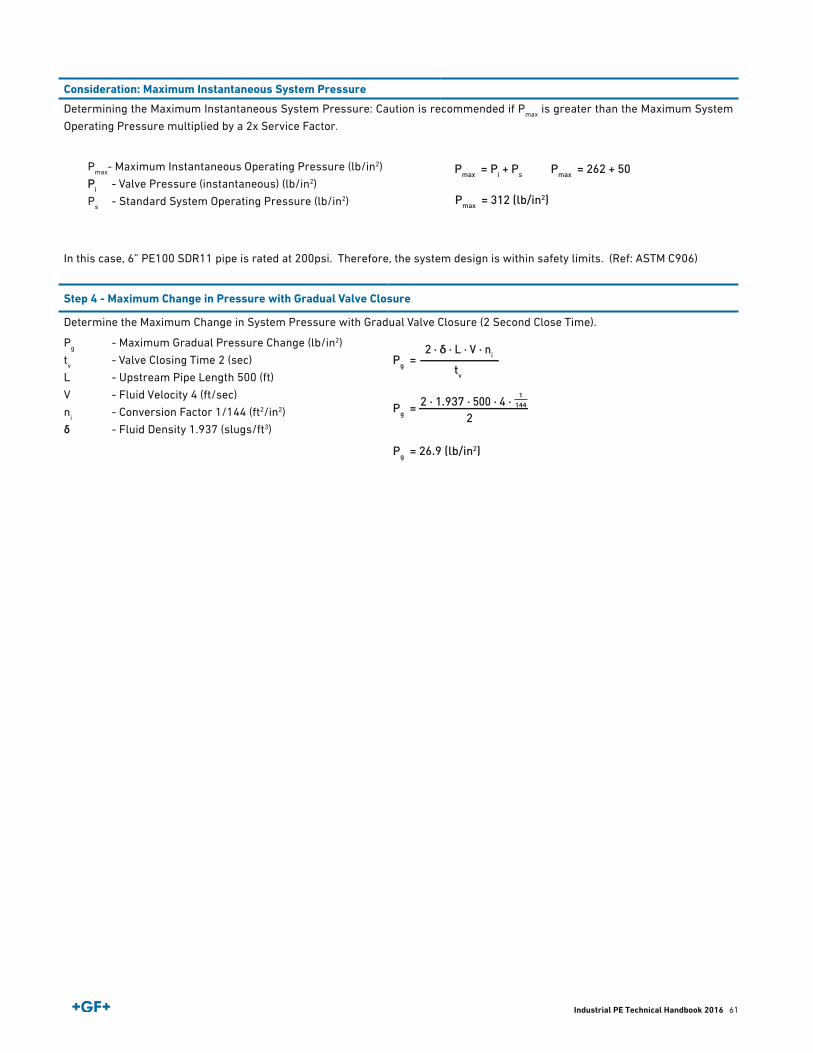
61Industrial PE Technical Handbook 2016
Consideration: Maximum Instantaneous System Pressure
Determining the Maximum Instantaneous System Pressure: Caution is recommended if Pmax
is greater than the Maximum System
Operating Pressure multiplied by a 2x Service Factor .
Pmax
- Maximum Instantaneous Operating Pressure (lb/in2)
Pi - Valve Pressure (instantaneous) (lb/in2)
Ps - Standard System Operating Pressure (lb/in2)
Vw =K
ni · δ √ 3.19 x 105
· 1.937 √ 1144
Vw = Vw = 4870 (ft/sec)
STEP 1:
STEP 2:
STEP 3:
tc =2LVw
Pg =2 · δ · L · V · ni
tv
tc =2 · 5004870
tc = 0.2 (sec)
Pi = δ · V · Vw ni Pi =1.937 · 4 · 4870
144Pi = 262 (lb/in2)
STEP 4:
STEP 5:
Pmax = Pi + Ps Pmax = 262 + 50 Pmax = 312 (lb/in2)
Pg =2 · 1.937 · 500 · 4 ·
2Pg = 26.9 (lb/in2)
1144
Pmax = Pg + Ps Pmax = 26.9 + 50 = 76.9 (lb/in2)
In this case, 6” PE100 SDR11 pipe is rated at 200psi . Therefore, the system design is within safety limits . (Ref: ASTM C906)
Step 4 - Maximum Change in Pressure with Gradual Valve Closure
Determine the Maximum Change in System Pressure with Gradual Valve Closure (2 Second Close Time) .
Pg - Maximum Gradual Pressure Change (lb/in2)
tv - Valve Closing Time 2 (sec)
L - Upstream Pipe Length 500 (ft)
V - Fluid Velocity 4 (ft/sec)
ni - Conversion Factor 1/144 (ft2/in2)
δ - Fluid Density 1 .937 (slugs/ft3)
Vw =K
ni · δ √ 3.19 x 105
· 1.937 √ 1144
Vw = Vw = 4870 (ft/sec)
STEP 1:
STEP 2:
STEP 3:
tc =2LVw
Pg =2 · δ · L · V · ni
tv
tc =2 · 5004870
tc = 0.2 (sec)
Pi = δ · V · Vw ni Pi =1.937 · 4 · 4870
144Pi = 262 (lb/in2)
STEP 4:
STEP 5:
Pmax = Pi + Ps Pmax = 262 + 50 Pmax = 312 (lb/in2)
Pg =2 · 1.937 · 500 · 4 ·
2Pg = 26.9 (lb/in2)
1144
Pmax = Pg + Ps Pmax = 26.9 + 50 = 76.9 (lb/in2)
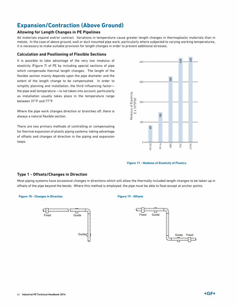
62 Industrial PE Technical Handbook 2016
Expansion/Contraction (Above Ground)Allowing for Length Changes in PE PipelinesAll materials expand and/or contract . Variations in temperature cause greater length changes in thermoplastic materials than in metals . In the case of above ground, wall or duct mounted pipe work, particularly where subjected to varying working temperatures, it is necessary to make suitable provision for length changes in order to prevent additional stresses .
Calculation and Positioning of Flexible SectionsIt is possible to take advantage of the very low modulus of
elasticity (Figure 7) of PE by including special sections of pipe
which compensate thermal length changes . The length of the
flexible section mainly depends upon the pipe diameter and the
extent of the length change to be compensated . In order to
simplify planning and installation, the third influencing factor—
the pipe wall temperature —is not taken into account, particularly
as installation usually takes place in the temperature range
between 37°F and 77°F .
Where the pipe work changes direction or branches off, there is
always a natural flexible section .
There are two primary methods of controlling or compensating
for thermal expansion of plastic piping systems: taking advantage
of offsets and changes of direction in the piping and expansion
loops . 0
100
200
300
400
87
330
150
420
423
PE1
00
AB
S
PP
-H
PVC
CP
VC
Mod
ulus
of E
last
icity
E x
10 (
PSI
)3
Figure 17 - Modulus of Elasticity of Plastics
Type 1 - Offsets/Changes in DirectionMost piping systems have occasional changes in directions which will allow the thermally included length changes to be taken up in
offsets of the pipe beyond the bends . Where this method is employed, the pipe must be able to float except at anchor points .
Figure 18 - Changes in Direction
a
6”min. 6”min.
L
Fixed Guide
FixedGuide
Fixed Guide
Guide
Fixed
Guide Guide
Fixed Guide
FixedGuide
Fixed Guide
Guide
Fixed
Guide Guide
1/5a
2/5a
1/4a
1/2a
1/4a
Figure 19 - Offsets
a
6”min. 6”min.
L
Fixed Guide
FixedGuide
Fixed Guide
Guide
Fixed
Guide Guide
Fixed Guide
FixedGuide
Fixed Guide
Guide
Fixed
Guide Guide
1/5a
2/5a
1/4a
1/2a
1/4a
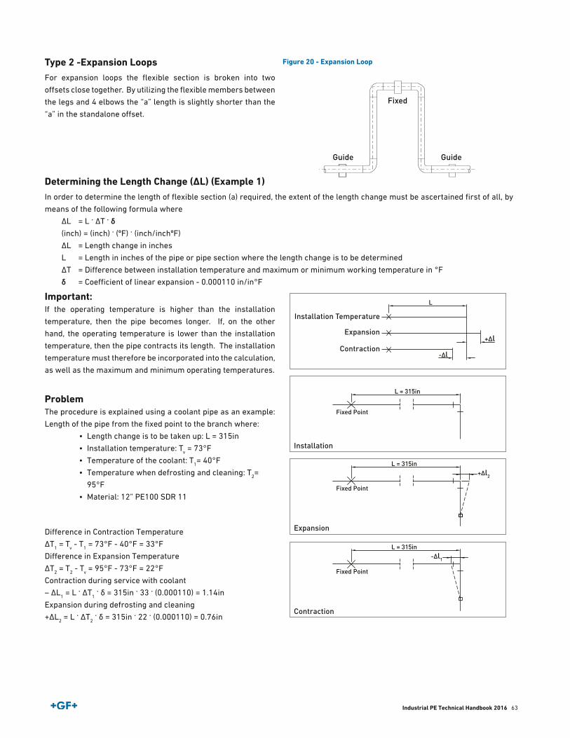
63Industrial PE Technical Handbook 2016
Type 2 -Expansion LoopsFor expansion loops the flexible section is broken into two
offsets close together . By utilizing the flexible members between
the legs and 4 elbows the “a” length is slightly shorter than the
“a” in the standalone offset .
Figure 20 - Expansion Loop
a
6”min. 6”min.
L
Fixed Guide
FixedGuide
Fixed Guide
Guide
Fixed
Guide Guide
Fixed Guide
FixedGuide
Fixed Guide
Guide
Fixed
Guide Guide
1/5a
2/5a
1/4a
1/2a
1/4a
Determining the Length Change (ΔL) (Example 1)In order to determine the length of flexible section (a) required, the extent of the length change must be ascertained first of all, by
means of the following formula where
∆L = L · ∆T · δ
(inch) = (inch) · (ºF) · (inch/inchºF)
ΔL = Length change in inches
L = Length in inches of the pipe or pipe section where the length change is to be determined
ΔT = Difference between installation temperature and maximum or minimum working temperature in °F
δ = Coefficient of linear expansion - 0 .000110 in/in°F
Important: If the operating temperature is higher than the installation
temperature, then the pipe becomes longer . If, on the other
hand, the operating temperature is lower than the installation
temperature, then the pipe contracts its length . The installation
temperature must therefore be incorporated into the calculation,
as well as the maximum and minimum operating temperatures .
ProblemThe procedure is explained using a coolant pipe as an example:
Length of the pipe from the fixed point to the branch where:
• Length change is to be taken up: L = 315in
• Installation temperature: Tv = 73°F
• Temperature of the coolant: T1= 40°F
• Temperature when defrosting and cleaning: T2=
95°F
• Material: 12” PE100 SDR 11
Difference in Contraction Temperature
ΔT1 = T
v - T
1 = 73°F - 40°F = 33°F
Difference in Expansion Temperature
ΔT2 = T
2 - T
v = 95°F - 73°F = 22°F
Contraction during service with coolant
– ΔL1 = L · ΔT
1 · δ = 315in · 33 · (0 .000110) = 1 .14in
Expansion during defrosting and cleaning
+ΔL2 = L · ΔT
2 · δ = 315in · 22 · (0 .000110) = 0 .76in
Installation Temperature
+Δl
-Δl
L
Expansion
Contraction
L = 315in
Fixed Point
L = 315in
Fixed Point
+Δl2
L = 315in
Fixed Point
-Δl1
Expansion
Contraction
Installation
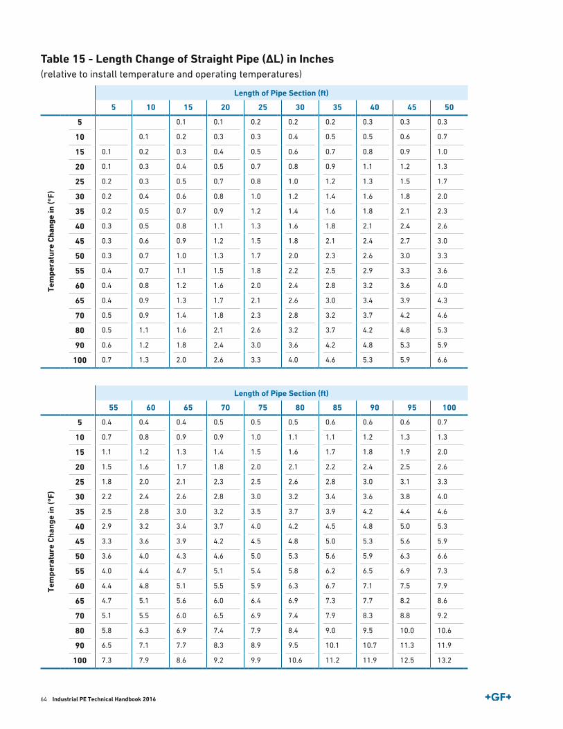
64 Industrial PE Technical Handbook 2016
Table 15 - Length Change of Straight Pipe (ΔL) in Inches(relative to install temperature and operating temperatures)
Length of Pipe Section (ft)
5 10 15 20 25 30 35 40 45 50
Tem
pera
ture
Cha
nge
in (°
F)
5 0 .1 0 .1 0 .2 0 .2 0 .2 0 .3 0 .3 0 .3
10 0 .1 0 .2 0 .3 0 .3 0 .4 0 .5 0 .5 0 .6 0 .7
15 0 .1 0 .2 0 .3 0 .4 0 .5 0 .6 0 .7 0 .8 0 .9 1 .0
20 0 .1 0 .3 0 .4 0 .5 0 .7 0 .8 0 .9 1 .1 1 .2 1 .3
25 0 .2 0 .3 0 .5 0 .7 0 .8 1 .0 1 .2 1 .3 1 .5 1 .7
30 0 .2 0 .4 0 .6 0 .8 1 .0 1 .2 1 .4 1 .6 1 .8 2 .0
35 0 .2 0 .5 0 .7 0 .9 1 .2 1 .4 1 .6 1 .8 2 .1 2 .3
40 0 .3 0 .5 0 .8 1 .1 1 .3 1 .6 1 .8 2 .1 2 .4 2 .6
45 0 .3 0 .6 0 .9 1 .2 1 .5 1 .8 2 .1 2 .4 2 .7 3 .0
50 0 .3 0 .7 1 .0 1 .3 1 .7 2 .0 2 .3 2 .6 3 .0 3 .3
55 0 .4 0 .7 1 .1 1 .5 1 .8 2 .2 2 .5 2 .9 3 .3 3 .6
60 0 .4 0 .8 1 .2 1 .6 2 .0 2 .4 2 .8 3 .2 3 .6 4 .0
65 0 .4 0 .9 1 .3 1 .7 2 .1 2 .6 3 .0 3 .4 3 .9 4 .3
70 0 .5 0 .9 1 .4 1 .8 2 .3 2 .8 3 .2 3 .7 4 .2 4 .6
80 0 .5 1 .1 1 .6 2 .1 2 .6 3 .2 3 .7 4 .2 4 .8 5 .3
90 0 .6 1 .2 1 .8 2 .4 3 .0 3 .6 4 .2 4 .8 5 .3 5 .9
100 0 .7 1 .3 2 .0 2 .6 3 .3 4 .0 4 .6 5 .3 5 .9 6 .6
Length of Pipe Section (ft)
55 60 65 70 75 80 85 90 95 100
Tem
pera
ture
Cha
nge
in (°
F)
5 0 .4 0 .4 0 .4 0 .5 0 .5 0 .5 0 .6 0 .6 0 .6 0 .7
10 0 .7 0 .8 0 .9 0 .9 1 .0 1 .1 1 .1 1 .2 1 .3 1 .3
15 1 .1 1 .2 1 .3 1 .4 1 .5 1 .6 1 .7 1 .8 1 .9 2 .0
20 1 .5 1 .6 1 .7 1 .8 2 .0 2 .1 2 .2 2 .4 2 .5 2 .6
25 1 .8 2 .0 2 .1 2 .3 2 .5 2 .6 2 .8 3 .0 3 .1 3 .3
30 2 .2 2 .4 2 .6 2 .8 3 .0 3 .2 3 .4 3 .6 3 .8 4 .0
35 2 .5 2 .8 3 .0 3 .2 3 .5 3 .7 3 .9 4 .2 4 .4 4 .6
40 2 .9 3 .2 3 .4 3 .7 4 .0 4 .2 4 .5 4 .8 5 .0 5 .3
45 3 .3 3 .6 3 .9 4 .2 4 .5 4 .8 5 .0 5 .3 5 .6 5 .9
50 3 .6 4 .0 4 .3 4 .6 5 .0 5 .3 5 .6 5 .9 6 .3 6 .6
55 4 .0 4 .4 4 .7 5 .1 5 .4 5 .8 6 .2 6 .5 6 .9 7 .3
60 4 .4 4 .8 5 .1 5 .5 5 .9 6 .3 6 .7 7 .1 7 .5 7 .9
65 4 .7 5 .1 5 .6 6 .0 6 .4 6 .9 7 .3 7 .7 8 .2 8 .6
70 5 .1 5 .5 6 .0 6 .5 6 .9 7 .4 7 .9 8 .3 8 .8 9 .2
80 5 .8 6 .3 6 .9 7 .4 7 .9 8 .4 9 .0 9 .5 10 .0 10 .6
90 6 .5 7 .1 7 .7 8 .3 8 .9 9 .5 10 .1 10 .7 11 .3 11 .9
100 7 .3 7 .9 8 .6 9 .2 9 .9 10 .6 11 .2 11 .9 12 .5 13 .2
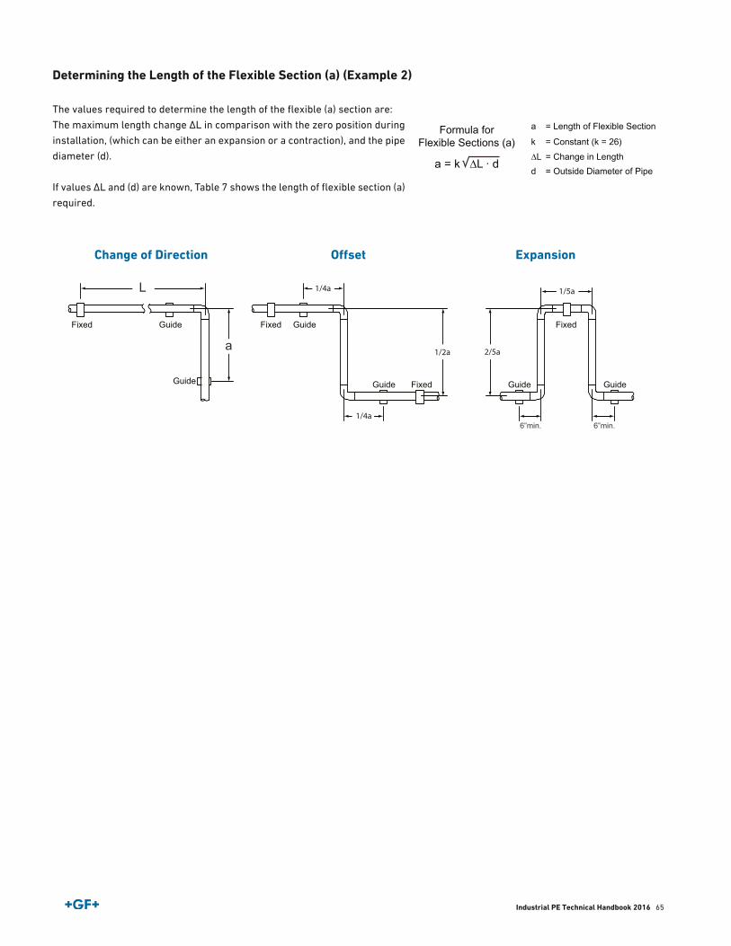
65Industrial PE Technical Handbook 2016
Determining the Length of the Flexible Section (a) (Example 2)
The values required to determine the length of the flexible (a) section are:
The maximum length change ΔL in comparison with the zero position during
installation, (which can be either an expansion or a contraction), and the pipe
diameter (d) .
If values ΔL and (d) are known, Table 7 shows the length of flexible section (a)
required .
1.0
0.1
2.0
3.0
5.0
7.0
8.0
9.0
10.0
6.0
4.0
0.5
146.0135.0120.090.0 105.075.045.0 60.030.015.0
a = k ∆L · d
a
∆L ∆L
FlexibleSection
Formula forFlexible Sections (a)
a = Length of Flexible Section
k = Constant (k = 26)
∆L = Change in Length
d = Outside Diameter of Pipe
Leng
th C
hang
e (∆
L) in
inch
es
Flexible Section Length (a) in inches
2”
3”
4”
6”
8”
10”
12”
14”
16”
20”
24”
28”
32”
18”
22 ”
26”
30”
36”
Nom
inal
Pip
e S
ize
(d =
Act
ual O
D)
0.6
0.9
0.7
0.8
1.6
1.1
1.2
1.5
1.3
1.4
1.9
1.7
1.8
Change of Direction
a
6”min. 6”min.
L
Fixed Guide
FixedGuide
Fixed Guide
Guide
Fixed
Guide Guide
Fixed Guide
FixedGuide
Fixed Guide
Guide
Fixed
Guide Guide
1/5a
2/5a
1/4a
1/2a
1/4a
Offset
a
6”min. 6”min.
L
Fixed Guide
FixedGuide
Fixed Guide
Guide
Fixed
Guide Guide
Fixed Guide
FixedGuide
Fixed Guide
Guide
Fixed
Guide Guide
1/5a
2/5a
1/4a
1/2a
1/4a
Expansion
a
6”min. 6”min.
L
Fixed Guide
FixedGuide
Fixed Guide
Guide
Fixed
Guide Guide
Fixed Guide
FixedGuide
Fixed Guide
Guide
Fixed
Guide Guide
1/5a
2/5a
1/4a
1/2a
1/4a
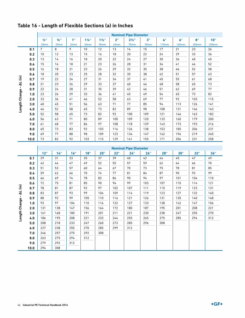
66 Industrial PE Technical Handbook 2016
Table 16 - Length of Flexible Sections (a) in Inches
Nominal Pipe Diameter½“ ¾“ 1“ 1¼“ 1½“ 2“ 2½“ 3“ 4“ 6“ 8“ 10“
20mm 25mm 32mm 40mm 50mm 63mm 75mm 90mm 110mm 160mm 200mm 250mm
Leng
th C
hang
e -
ΔL
(in)
0.1 7 8 9 10 12 13 14 15 17 21 23 26
0.2 10 12 13 15 16 18 20 22 24 29 33 36
0.3 13 14 16 18 20 22 24 27 30 36 40 45
0.4 15 16 18 21 23 26 28 31 34 41 46 52
0.5 16 18 21 23 26 29 32 35 38 46 52 58
0.6 18 20 23 25 28 32 35 38 42 51 57 63
0.7 19 22 24 27 31 34 37 41 45 55 61 68
0.8 21 23 26 29 33 37 40 44 48 58 65 73
0.9 22 24 28 31 35 39 42 46 51 62 69 77
1.0 23 26 29 33 36 41 45 49 54 65 73 82
2.0 33 36 41 46 52 58 63 69 77 92 103 115
3.0 40 45 51 56 63 71 77 85 94 113 126 141
4.0 46 52 58 65 73 82 89 98 108 131 146 163
5.0 52 58 65 73 82 92 100 109 121 146 163 182
6.0 56 63 71 80 89 100 109 120 133 160 179 200
7.0 61 68 77 86 97 108 118 129 143 173 193 216
8.0 65 73 83 92 103 116 126 138 153 185 206 231
9.0 69 77 88 98 109 123 134 147 162 196 219 245
10.0 73 82 92 103 115 129 141 155 171 206 231 258
Nominal Pipe Diameter12“ 14“ 16“ 18“ 20“ 22“ 24“ 26“ 28“ 30“ 32“ 36“
Leng
th C
hang
e -
ΔL
(in)
0.1 29 31 33 35 37 39 40 42 44 45 47 49
0.2 42 44 47 49 52 55 57 59 62 64 66 70
0.3 51 53 57 60 64 67 70 73 75 78 81 85
0.4 59 62 66 70 74 77 81 84 87 90 93 99
0.5 66 69 74 78 82 86 90 94 97 101 104 110
0.6 72 75 81 85 90 94 99 103 107 110 114 121
0.7 78 81 87 92 97 102 107 111 115 119 123 131
0.8 83 87 93 99 104 109 114 119 123 127 132 140
0.9 88 92 99 105 110 116 121 126 131 135 140 148
1.0 93 97 104 110 116 122 127 133 138 142 147 156
2.0 131 138 147 156 164 172 180 187 195 201 208 221
3.0 161 168 180 191 201 211 221 230 238 247 255 270
4.0 186 195 208 221 233 244 255 265 275 285 294 312
5.0 208 218 233 247 260 273 285 296 308
6.0 227 238 255 270 285 299 312
7.0 246 257 275 292 308
8.0 263 275 294 312
9.0 279 292 312
10.0 294 308
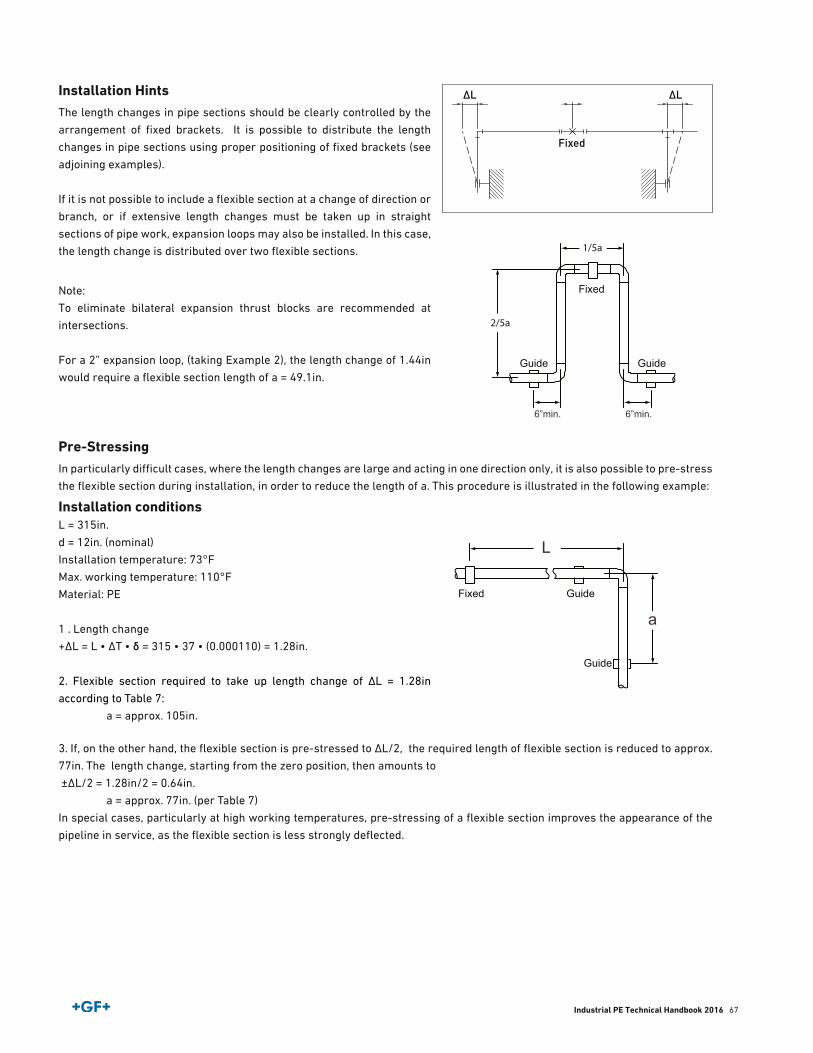
67Industrial PE Technical Handbook 2016
Installation HintsThe length changes in pipe sections should be clearly controlled by the
arrangement of fixed brackets . It is possible to distribute the length
changes in pipe sections using proper positioning of fixed brackets (see
adjoining examples) .
If it is not possible to include a flexible section at a change of direction or
branch, or if extensive length changes must be taken up in straight
sections of pipe work, expansion loops may also be installed . In this case,
the length change is distributed over two flexible sections .
Note:
To eliminate bilateral expansion thrust blocks are recommended at
intersections .
For a 2” expansion loop, (taking Example 2), the length change of 1 .44in
would require a flexible section length of a = 49 .1in .
ΔL ΔL
LL/2 L/2
L = 394in - ΔL/2
a = 3.84in
a = 1.92in
L = 394in
Not Recommended Recommended
Fixed
F F
ΔL ΔL/2 ΔL/2
ΔL/2 ΔL/2
F
F F
ΔL
ΔL/2
F
F
a
6”min. 6”min.
L
Fixed Guide
FixedGuide
Fixed Guide
Guide
Fixed
Guide Guide
Fixed Guide
FixedGuide
Fixed Guide
Guide
Fixed
Guide Guide
1/5a
2/5a
1/4a
1/2a
1/4a
Pre-StressingIn particularly difficult cases, where the length changes are large and acting in one direction only, it is also possible to pre-stress
the flexible section during installation, in order to reduce the length of a . This procedure is illustrated in the following example:
Installation conditionsL = 315in .
d = 12in . (nominal)
Installation temperature: 73°F
Max . working temperature: 110°F
Material: PE
1 . Length change
+ΔL = L • ΔT • δ = 315 • 37 • (0 .000110) = 1 .28in .
2 . Flexible section required to take up length change of ΔL = 1 .28in
according to Table 7:
a = approx . 105in .
a
6”min. 6”min.
L
Fixed Guide
FixedGuide
Fixed Guide
Guide
Fixed
Guide Guide
Fixed Guide
FixedGuide
Fixed Guide
Guide
Fixed
Guide Guide
1/5a
2/5a
1/4a
1/2a
1/4a
3 . If, on the other hand, the flexible section is pre-stressed to ΔL/2, the required length of flexible section is reduced to approx .
77in . The length change, starting from the zero position, then amounts to
±ΔL/2 = 1 .28in/2 = 0 .64in .
a = approx . 77in . (per Table 7)
In special cases, particularly at high working temperatures, pre-stressing of a flexible section improves the appearance of the
pipeline in service, as the flexible section is less strongly deflected .

68 Industrial PE Technical Handbook 2016
InstallationThe Incorporation of ValvesValves should be mounted as directly as possible; they should be formed as fixed points . The actuating force is thus transmitted
directly, and not through the pipeline . The length changes, starting from the valve, are to be controlled as described previously .
Note:
• All Plastic Valves that include additional accessories, actuators or items that will increase load or stress on the piping system
must be fully supported either independently or by mounting points located on the valve body .
• All metal valves must be supported . Should metal valves not be adequately supported, there is a significant risk of stress fatigue
and possible system failure .
• For safe mounting of plastic valves, Georg Fischer valves are equipped with metal threaded inserts for direct mounted
installation .
Vibration DampenersThere are two principal ways to control stress caused by vibration . You can usually observe the stability of the system during initial
operation and add restraints or supports as required to reduce effects of equipment vibration . Where necessary restraint fittings may
be used to effectively hold pipe from lifting or moving laterally .
In special cases where the source of vibration is excessive (such as that resulting from pumps running unbalanced), an elastomeric
expansion joint or other vibration absorber may be considered . This may be the case at pumps where restricting the source of
vibration is not recommended .
Pipe Bracket Support Centers and Fixation of Plastic PipelinesGeneral Pipe Supports and BracketsPE pipelines need to be supported at specific intervals, depending upon the material, the average pipe wall temperature, the specific
gravity of the medium, and the diameter and wall thickness of the pipe . The determination of the pipe support centers has been based
on the permissible amount of deflection of the pipe between two brackets . The pipe bracket centers given in Table 8 are calculated
on the basis of a permissible deflection of max . 0 .01 inch (0 .25 cm) between two brackets .
Pipe Bracket Spacing in the Case of Fluids with Specific Gravity ≤ 1 .0 (62 .4 Lb/Ft3)
Where fluids with a specific gravity exceeding 1g/cm3 are to be conveyed, the pipe bracket centers given in Table 8 must be divided by
the specific gravity of the solution .
Example: 20” pipe carrying media with a specific gravity of 1 .6 = 13ft divided by 1 .6 = approx . 8 .1ft centers .
Installation of Closely Spaced Pipe Brackets
A continuous support may be more advantageous and economical than pipe brackets for small diameter horizontal pipe work,
especially in a higher temperature range . Installation in a “V” or “U” shaped support made of metal or heat-resistant plastic material
has proven satisfactory .
Pipe Bracket Requirements
When mounted, the inside diameter of the bracket must be greater than the outside diameter of the pipe, in order to allow length
changes of the pipe at the specified points . The inside edges of the pipe bracket must be formed in such a way that no damage to the
pipe surface is possible . George Fischer pipe brackets meet these requirements . They are made of plastic and may be used under
rugged working conditions and also in areas where the pipe work is subjected to the external influence of aggressive atmospheres or
media . Georg Fischer pipe brackets are suitable for PE, PVC, CPVC, PP and PVDF pipes .
Arrangement of Fixed Brackets
If the pipe bracket is positioned directly beside a fitting, the length change of the pipeline is limited to one direction only (one-sided
fixed point) .
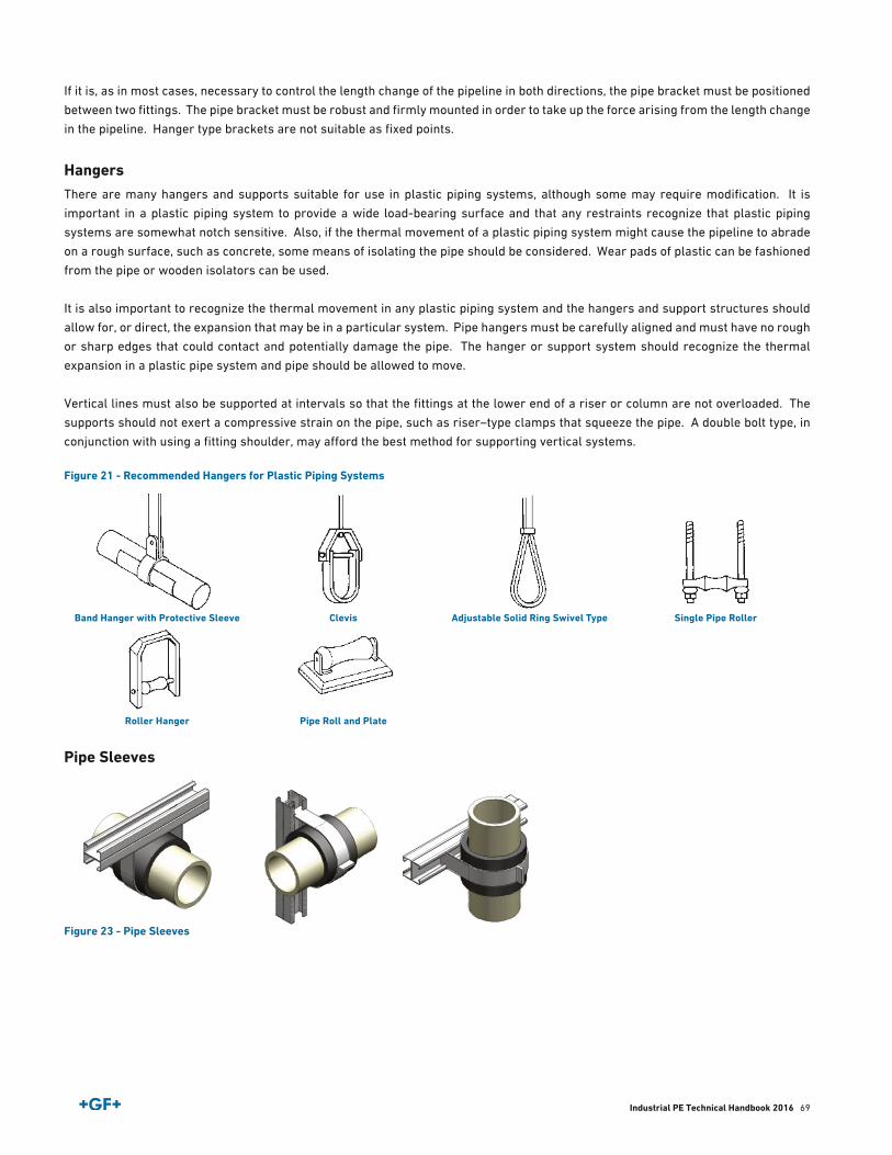
69Industrial PE Technical Handbook 2016
If it is, as in most cases, necessary to control the length change of the pipeline in both directions, the pipe bracket must be positioned
between two fittings . The pipe bracket must be robust and firmly mounted in order to take up the force arising from the length change
in the pipeline . Hanger type brackets are not suitable as fixed points .
HangersThere are many hangers and supports suitable for use in plastic piping systems, although some may require modification . It is
important in a plastic piping system to provide a wide load-bearing surface and that any restraints recognize that plastic piping
systems are somewhat notch sensitive . Also, if the thermal movement of a plastic piping system might cause the pipeline to abrade
on a rough surface, such as concrete, some means of isolating the pipe should be considered . Wear pads of plastic can be fashioned
from the pipe or wooden isolators can be used .
It is also important to recognize the thermal movement in any plastic piping system and the hangers and support structures should
allow for, or direct, the expansion that may be in a particular system . Pipe hangers must be carefully aligned and must have no rough
or sharp edges that could contact and potentially damage the pipe . The hanger or support system should recognize the thermal
expansion in a plastic pipe system and pipe should be allowed to move .
Vertical lines must also be supported at intervals so that the fittings at the lower end of a riser or column are not overloaded . The
supports should not exert a compressive strain on the pipe, such as riser–type clamps that squeeze the pipe . A double bolt type, in
conjunction with using a fitting shoulder, may afford the best method for supporting vertical systems .
Figure 21 - Recommended Hangers for Plastic Piping Systems
Band Hanger with Protective Sleeve Clevis Adjustable Solid Ring Swivel Type Single Pipe Roller
Roller Hanger Pipe Roll and Plate
Pipe Sleeves
Figure 23 - Pipe Sleeves
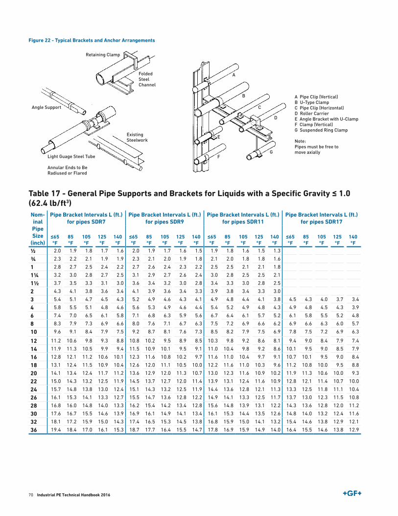
70 Industrial PE Technical Handbook 2016
Figure 22 - Typical Brackets and Anchor Arrangements
A Pipe Clip (Vertical)B U-Type ClampC Pipe Clip (Horizontal)D Roller CarrierE Angle Bracket with U-ClampF Clamp (Vertical)G Suspended Ring Clamp
Note:Pipes must be free tomove axially
Retaining Clamp
FoldedSteelChannel
Angle Support
Light Guage Steel Tube
Annular Ends to BeRadiused or Flared
ExistingSteelwork
A
B
C
D
E
FG
Table 17 - General Pipe Supports and Brackets for Liquids with a Specific Gravity ≤ 1.0 (62.4 lb/ft3)Nom-inal Pipe Size
(inch)
Pipe Bracket Intervals L (ft.) for pipes SDR7
Pipe Bracket Intervals L (ft.) for pipes SDR9
Pipe Bracket Intervals L (ft.) for pipes SDR11
Pipe Bracket Intervals L (ft.) for pipes SDR17
≤65°F
85°F
105°F
125°F
140°F
≤65 °F
85 °F
105 °F
125 °F
140 °F
≤65 °F
85 °F
105 °F
125 °F
140 °F
≤65 °F
85 °F
105 °F
125 °F
140 °F
½ 2 .0 1 .9 1 .8 1 .7 1 .6 2 .0 1 .9 1 .7 1 .6 1 .5 1 .9 1 .8 1 .6 1 .5 1 .3
¾ 2 .3 2 .2 2 .1 1 .9 1 .9 2 .3 2 .1 2 .0 1 .9 1 .8 2 .1 2 .0 1 .8 1 .8 1 .6
1 2 .8 2 .7 2 .5 2 .4 2 .2 2 .7 2 .6 2 .4 2 .3 2 .2 2 .5 2 .5 2 .1 2 .1 1 .8
1¼ 3 .2 3 .0 2 .8 2 .7 2 .5 3 .1 2 .9 2 .7 2 .6 2 .4 3 .0 2 .8 2 .5 2 .5 2 .1
1½ 3 .7 3 .5 3 .3 3 .1 3 .0 3 .6 3 .4 3 .2 3 .0 2 .8 3 .4 3 .3 3 .0 2 .8 2 .5
2 4 .3 4 .1 3 .8 3 .6 3 .4 4 .1 3 .9 3 .6 3 .4 3 .3 3 .9 3 .8 3 .4 3 .3 3 .0
3 5 .4 5 .1 4 .7 4 .5 4 .3 5 .2 4 .9 4 .6 4 .3 4 .1 4 .9 4 .8 4 .4 4 .1 3 .8 4 .5 4 .3 4 .0 3 .7 3 .4
4 5 .8 5 .5 5 .1 4 .8 4 .6 5 .6 5 .3 4 .9 4 .6 4 .4 5 .4 5 .2 4 .9 4 .8 4 .3 4 .9 4 .8 4 .5 4 .3 3 .9
6 7 .4 7 .0 6 .5 6 .1 5 .8 7 .1 6 .8 6 .3 5 .9 5 .6 6 .7 6 .4 6 .1 5 .7 5 .2 6 .1 5 .8 5 .5 5 .2 4 .8
8 8 .3 7 .9 7 .3 6 .9 6 .6 8 .0 7 .6 7 .1 6 .7 6 .3 7 .5 7 .2 6 .9 6 .6 6 .2 6 .9 6 .6 6 .3 6 .0 5 .7
10 9 .6 9 .1 8 .4 7 .9 7 .5 9 .2 8 .7 8 .1 7 .6 7 .3 8 .5 8 .2 7 .9 7 .5 6 .9 7 .8 7 .5 7 .2 6 .9 6 .3
12 11 .2 10 .6 9 .8 9 .3 8 .8 10 .8 10 .2 9 .5 8 .9 8 .5 10 .3 9 .8 9 .2 8 .6 8 .1 9 .4 9 .0 8 .4 7 .9 7 .4
14 11 .9 11 .3 10 .5 9 .9 9 .4 11 .5 10 .9 10 .1 9 .5 9 .1 11 .0 10 .4 9 .8 9 .2 8 .6 10 .1 9 .5 9 .0 8 .5 7 .9
16 12 .8 12 .1 11 .2 10 .6 10 .1 12 .3 11 .6 10 .8 10 .2 9 .7 11 .6 11 .0 10 .4 9 .7 9 .1 10 .7 10 .1 9 .5 9 .0 8 .4
18 13 .1 12 .4 11 .5 10 .9 10 .4 12 .6 12 .0 11 .1 10 .5 10 .0 12 .2 11 .6 11 .0 10 .3 9 .6 11 .2 10 .8 10 .0 9 .5 8 .8
20 14 .1 13 .4 12 .4 11 .7 11 .2 13 .6 12 .9 12 .0 11 .3 10 .7 13 .0 12 .3 11 .6 10 .9 10 .2 11 .9 11 .3 10 .6 10 .0 9 .3
22 15 .0 14 .3 13 .2 12 .5 11 .9 14 .5 13 .7 12 .7 12 .0 11 .4 13 .9 13 .1 12 .4 11 .6 10 .9 12 .8 12 .1 11 .4 10 .7 10 .0
24 15 .7 14 .8 13 .8 13 .0 12 .4 15 .1 14 .3 13 .2 12 .5 11 .9 14 .4 13 .6 12 .8 12 .1 11 .3 13 .3 12 .5 11 .8 11 .1 10 .4
26 16 .1 15 .3 14 .1 13 .3 12 .7 15 .5 14 .7 13 .6 12 .8 12 .2 14 .9 14 .1 13 .3 12 .5 11 .7 13 .7 13 .0 12 .3 11 .5 10 .8
28 16 .8 16 .0 14 .8 14 .0 13 .3 16 .2 15 .4 14 .2 13 .4 12 .8 15 .6 14 .8 13 .9 13 .1 12 .2 14 .3 13 .6 12 .8 12 .0 11 .2
30 17 .6 16 .7 15 .5 14 .6 13 .9 16 .9 16 .1 14 .9 14 .1 13 .4 16 .1 15 .3 14 .4 13 .5 12 .6 14 .8 14 .0 13 .2 12 .4 11 .6
32 18 .1 17 .2 15 .9 15 .0 14 .3 17 .4 16 .5 15 .3 14 .5 13 .8 16 .8 15 .9 15 .0 14 .1 13 .2 15 .4 14 .6 13 .8 12 .9 12 .1
36 19 .4 18 .4 17 .0 16 .1 15 .3 18 .7 17 .7 16 .4 15 .5 14 .7 17 .8 16 .9 15 .9 14 .9 14 .0 16 .4 15 .5 14 .6 13 .8 12 .9

71Industrial PE Technical Handbook 2016
RestraintRestraint is rigidly anchoring the pipe runs to the building structure at appropriate places so that thermally-induced dimension
changes will be replaced by thermally-induced stresses . This can be accomplished by use of adequately strong clamps or supports
along with a properly engineered pipe clamp interface to hold the pipe in place . For horizontal runs, braced clamp type hangers may
be used . For floor penetrations, extension riser clamps may be used .
Underground installation in properly backfilled trenches may be considered to be a restrained system and not subject to thermally-
induced dimensional changes . For more details, see the FM section .
It should be noted that two unique properties of PE4710 make for the success of these methods of handling thermal expansion .
PE4710 is not subject to mechanical stress cracking . It can be stressed for long periods of time in what might be considered unfriendly
environments without harm . In addition, PE4710 has an extremely high fatigue life . Its “self-hinge” characteristics are well known and
the piping materials will stand repeated drastic flexures without harm .
Cold Weather InstallationsIn general, it is good practice when possible, to maintain an ambient temperature above 40˚F (4˚C) . However, low temperature fusions
to -10˚F (-23˚C) are easily accomplished utilizing automatic temperature compensation capable fusion machines
(MSA 330/340) from GF .
Note: Material and fusion machines must be the same temperature prior to fusion . This can be achieved when components and
machines are in the same environment for 1 hour per ½” material wall thickness .For further information, please consult you local sales representative.
Flammability and Fire Rated ConstructionThe fire protection officials and code officials are becoming sensitive to the smoke generation and flammability of plastic materials
used in building construction, and plastic piping is naturally included in these concerns . To satisfy the fire safety requirements set
out by the authorities, the engineers and architects must have a better understanding of the plastics used in piping, appropriate test
methods and means of protection against fire dangers attributed to plastic piping .
To put this into the proper perspective, the architect, engineer and administrative authority must realize that, in the vast majority of
cases, fires commonly start and continue to develop in occupied areas of a building and not within the walls and chases where plastic
piping is more commonly installed .
Laboratory Fire TestsThe following are common laboratory tests conducted on small samples of plastic material and are useful in characterizing and
comparing different plastics . However, these tests are of only limited use in predicting the behavior of the materials in real fire
situations .
ASTM D635 - Rate of Burning and/or Extent and Time of Burning of Self Supporting Plastics in a Horizon-tal PositionOne half-inch wide by five-inch long horizontal specimens are exposed to a burner flame . The time of burning and distance burned
are recorded . The results are reported as measured, except in the case where the minimum values apply (time of burning is “less
than five seconds” and the minimum extent of burning is “less than one quarter-inch”) .
UL94 - Standard for Safety of Flammability of Plastic MaterialsOne half-inch wide by five-inch long vertical specimens are exposed repeatedly to a burner flame . Time of burning, possible dripping
of burning particles and afterglow are observed . Results are reported as V-0, V-1 or V-2, depending on test results .
72 Industrial PE Technical Handbook 2016
ASTM D2843 - Density of Smoke from the Burning or Decomposition of PlasticsA one-quarter inch by one inch by one inch sample is exposed to a propane burner flame and light transmission through the smoke
generated by the burning plastic is measured with a standard lamp and photocell for four minutes . Results are reported as light
absorption and smoke density .
ASTM D2863 - Minimum Oxygen Concentration to Support Candle-Like Combustion of Plastics (Oxygen Index)
A one-eighth inch by one-quarter inch by three to six inch long specimen is burned in a variable oxygen-nitrogen mixture to determine the percentage oxygen required to maintain combustion.
Large Scale Tests These tests are run on full-sized wall or floor (floor-ceiling) assemblies or on large material specimens . They are intended to
determine the response of varying construction methods and materials in actual fire conditions .
ASTM E119 - Fire Tests of Building Construction and Materials NFPA251 • UL263
• UBC43-1
Wall sections of at least 100 square feet in size are attached as the front wall of a furnace and exposed to a flaming environment . The
temperature rises according to a standard time temperature curve . The test specimen may or may not be exposed to vertical or
horizontal loads . The specimen, after exposure, may be subjected to a high pressure hose stream to determine its integrity after
exposure .
This test is universally accepted as the method of rating wall assemblies for fire resistance as related to time of exposure . Ratings
may be 1, 2, 3 or 4 hours, depending on the time for the temperature to rise to not more than 250°F (121°C) above its initial temperature
on the non-exposed face . Floor and floor-ceiling assemblies of at least 180 square feet in size are also tested per ASTM E119 as the
roofs of a floor-ceiling furnace, and rated on the basis of the time for the temperature to rise 250°F (121°C) above the initial temperature
on the unexposed face, as for walls .
ASTM E814 - Fire Tests of Through-Penetration Fire StopsThis test method (published Spring 1982) is essentially identical to the ASTM E119 test except that it is intended to determine the
ability of fire-stopping methods and devices to maintain the fire rating (integrity) of rated fire-resistive walls, floors or floor-ceiling
assemblies which are penetrated by pipe, conduits or cables .
ASTM E84 - Surface Burning Characteristics of Building Materials • NFPA255
• UL723
• UBC42-1
As stated, this test is intended for testing of surface finish materials which are capable of supporting themselves or of being supported
other than by support on the under-side of the test specimen . Samples are 20 inches (min .) wide by 24 feet long and are attached to
the roof of an 18 inch by 30 foot furnace .
Burning characteristics of the samples are stated as percentage of the rate of burning of red oak .
This test, being specifically aimed at testing surface finish materials, is recognized as not applying to plastic pipe by those who
understand the test method and application environment . The National Fire Protection Association has stated that the test is not to
be applied to plastic pipe and that the pipe should be tested as a component of a wall or floor assembly in the ASTM E119 test, where
the materials are most commonly used .
Fire Protection Methods for Wall Penetration and Return Air PlenumsFor fire resistance rated wall penetrations, penetrations through horizontal assemblies, etc . use listed and approved firestopping
with ratings determined by ASTM E814 or UL1479 for use with plastic piping .
73Industrial PE Technical Handbook 2016
Section 3: FM Factory Mutual
IntroductionFactory mutual (FM) approved piping systems – used for water supply in fire protection systems
Factory Mutual Global (FM) insures and protects the lives, property, and continuity of operation for its insureds, by mitigating fire risk .
One component of that risk minimization is the rigorous testing of fire protection system components, which includes underground
pipe and fittings . Factory Mutual Research Corp . is the FM Nationally Recognized Testing Laboratory (NRTL) which conducts pipe and
fittings testing for FM Global Insc . Fire protection system components are rigorously tested to ensure that all approved products pass
the aggressive level of FM performance, efficacy and quality requirements . Every GF product labeled with the Factory Mutual (FM)
symbol has met the strenuous requirements for fire protection systems . The GF manufacturing processes and the in-house testing
have been audited, approved, and biannually inspected by Factory Mutual Global, to assure product conformance and performance
for the Owner’s security and peace of mind, now, and into the future .
Benefits and features Many companies around the world design and build their
properties according to the FM standards . An essential part is
the selection, construction and installation of the buried fire-
protection piping system .
FM – Factory Mutual Global… is the world’s largest industrial property insurance and risk
management organization .
FM – Approval… .provides assurance that GF product design and
manufacturing, meets your fire system protection needs .
FM – Critical elements… Fire protection systems require moving water through pipes
from its source to its final point of use . Underground pipe and
fittings are considered the most critical components .
FM – Performance… fire prevention systems must be extremely reliable and
capable of safely withstanding both internal and external
stresses over long periods of time . Rigorous testing and
auditing by FM-approved personnel ensure reliability and
quality .
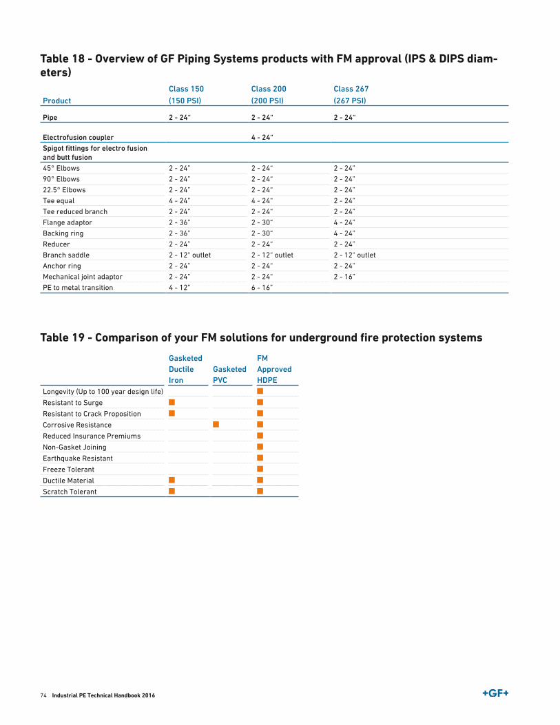
74 Industrial PE Technical Handbook 2016
Table 18 - Overview of GF Piping Systems products with FM approval (IPS & DIPS diam-eters)
Product
Class 150
(150 PSI)
Class 200
(200 PSI)
Class 267
(267 PSI)
Pipe 2 - 24“ 2 - 24“ 2 - 24“
Electrofusion coupler 4 - 24“
Spigot fittings for electro fusion and butt fusion
45° Elbows 2 - 24” 2 - 24“ 2 - 24”
90° Elbows 2 - 24” 2 - 24“ 2 - 24”
22 .5° Elbows 2 - 24” 2 - 24“ 2 - 24”
Tee equal 4 - 24” 4 - 24“ 2 - 24”
Tee reduced branch 2 - 24” 2 - 24“ 2 - 24”
Flange adaptor 2 - 36” 2 - 30“ 4 - 24”
Backing ring 2 - 36” 2 - 30“ 4 - 24”
Reducer 2 - 24” 2 - 24“ 2 - 24”
Branch saddle 2 - 12“ outlet 2 - 12“ outlet 2 - 12“ outlet
Anchor ring 2 - 24” 2 - 24“ 2 - 24”
Mechanical joint adaptor 2 - 24” 2 - 24“ 2 - 16”
PE to metal transition 4 - 12” 6 - 16”
Table 19 - Comparison of your FM solutions for underground fire protection systems
Gasketed Ductile Iron
Gasketed PVC
FM Approved HDPE
Longevity (Up to 100 year design life)
Resistant to Surge
Resistant to Crack Proposition
Corrosive Resistance
Reduced Insurance Premiums
Non-Gasket Joining
Earthquake Resistant
Freeze Tolerant
Ductile Material
Scratch Tolerant
75Industrial PE Technical Handbook 2016
System Specification: Factory Mutual Approved Pipe and Fittings Model
NOTICE: This document is intended as assistance and as a guide to support the design of fire protection piping systems . However, it
shall not be used as a substitute for the advice of a professional engineer to owners . GF has taken reasonable effort to ensure the
accuracy of this sample specification document, but it does not provide all necessary information, particularly with respect to custom
or unusual installations . No warranty or guarantee of piping installations is expressed nor implied . This sample specification is not
intended to provide nor act as a substitute for installation training nor instructions . This document may be changed from time to time
without notice .
1. General Terms and Conditions
1.1 ScopeThis specification covers Factory Mutual (FM) Approved and listed high-density polyethylene piping for underground fire main use,
made in accordance with the specification requirements of FM . All work shall be performed in accordance with these specifica-
tions . http://www .fmglobal .com/assets/pdf/fmapprovals/1613 .pdf
1.2 Engineered and Approved PlansUnderground fire main construction shall be performed in accordance with engineered construction plans for the work prepared
under the direction of a Professional Engineer . Guidance for polyethylene pipe design and construction is provided in the Plastic
Pipe Institute’s “Handbook of Polyethylene Pipe”, available at : http://www .plasticpipe .org/publications/pe-handbook .html
1.3 Referenced StandardsWhere all or part of a NSF, AWWA, ASTM, FM, NFPA, etc ., standard specification is incorporated by reference in this document, the
reference standard shall be the latest edition and revision .
1.4 Licenses and PermitsA licensed and bonded contractor shall perform all underground fire main construction work . The contractor shall secure all nec-
essary permits before commencing construction .
1.5 InspectionsAll work shall be inspected by an authorized representative of the owner who shall have the authority to halt construction if, in his
opinion, these specifications or standard construction practices are not being followed . Whenever any portion of these specifica-
tions is violated, the project engineer or his authorized representative shall, by written notice, order further construction to cease
until all deficiencies are corrected . A copy of the order shall be filed with the contractor’s license application for future review . If
the deficiencies are not corrected, performance shall be required of the contractor’s surety .
2. Polyethylene Pipe and Fittings
2.1 Qualification of ManufacturersThe manufacturer shall have manufacturing facilities and a quality assurance program that are FM Approved as being capable of
producing and assuring the quality of the pipe and fittings required by these specifications . The manufacturer’s production facili-
ties shall be open for inspection by the customer or his authorized representative . The project engineer shall approve qualified
manufacturers .
2.2 Approved ManufacturersManufacturers qualified and approved by the project engineer are listed below . Products from unapproved manufacturers are
prohibited .
Georg Fischer Central Plastics LLC
www .gfcp .com
GF Piping Systems (Global)
2.3 MaterialsMaterials used for the manufacture of polyethylene pipe and fittings shall be USA PE 4710 high density polyethylene meeting
ASTM D3350 cell classification 445574C for black or 445574E for color stripes, and shall be listed in PPI (Plastics Pipe Institute)
TR-4 with a standard grade HDB rating of 1600 psi at 73°F . This pipe grade HDPE material meets and exceeds the minimum
76 Industrial PE Technical Handbook 2016
performance requirements of PE3608 material, and is accepted and approved by FM for use in Class 150, Class 200, and Class
267 pipe and fittings .
2.3.1 Potable WaterWhen the main provides firewater and potable water service, the material shall also be listed and approved for potable water in
accordance with AWWA C901 and AWWA C906 .
2.4 Interchangeability of Pipe and FittingsThe FM Approved manufacturer who is qualified and approved by the project engineer shall supply both polyethylene pipe and
fittings . Products from non-approved manufacturers are prohibited . In the event of an emergency, pipe and fittings from different
manufacturers may be used if authorized by the engineer of record, if both are FM Approved and listed, and if both have the same
FM Approved ASTM material designation and material cell classification .
2.5 Polyethylene PipeFire main pipe shall be FM Approved Class 150, Class 200, or Class 267 IPS and/or DIPS OD- size polyethylene pipe, and shall be
marked with the authorized FM Approved logo . Each production lot of material or pipe shall be tested for melt index, density, and
percent carbon-black concentration . Each production lot of pipe shall be tested for dimensions and ring tensile strength . The Pipe
shall be produced, inspected, and tested IAW AWWA C901 and AWWA C906 .
2.5.1 Service Identification StripesFM Approved pipe surface may be provided as all black, or black with red stripes . Permanent identification of the striping shall
be provided by co-extruding at least 4 color stripes into the pipe outside surface . The striping material shall be the same material
as the pipe material except for color . IPS & DIPS sized pipes shall have four equally spaced, longitudinal color stripes . Except as
provided in 2 .5 .2, the optional stripe color shall be red .
2.5.2 Potable Water and Fire Main PipeDual-certified potable water and fire main pipe shall be FM Approved and AWWA approved, with an all-black surface or as black
with 4 blue stripes .
2.6 Polyethylene FittingsPolyethylene fittings can be molded or fabricated . The fittings manufacturer shall be FM Approved . Each fittings shall be marked
with the authorized FM Approval logo . Molded Fittings shall be provided by Georg Fischer-Central Plastics,LLC . Fabricated fittings
shall be provided by Georg Fischer Central Plastics LLC, an FM Approved fabrication manufacturer .
2.6.1 Polyethylene Flange AdaptersFlange adapters shall be FM Approved and shall be marked with the authorized FM Approval logo . Flange adapters shall have
sufficient through-bore length to be clamped in the butt fusion joining machine without the use of a stub-end holder . Flange
Adapters shall be joined in accordance with the guidance of the Plastic Pipe Institute Technical Note #38: http://www .plasticpipe .
org/pdf/tn-38_bolt_torque_flanged_joints .pdf
2.6.2 Back-up Rings & Flange BoltsClass 150, Class 200 and Class 267 flange adapters shall be fitted with FM Approved Bolt Rings . Flange bolts and nuts shall be
grade 3 or higher . Anodic corrosion protection of bolts should be considered for buried flange installations . http://marswater .
com/PDFs/SpecSheets/ZincCaps .pdf
2.6.3 MJ AdaptersMJ Adapters of each pressure class shall be FM Approved and shall be marked with the authorized FM Approval logo . MJ Gland
Rings shall be the C110 heavy Duty style, with all bolts evenly torqued to a range of 60-90 ft-lbs, per AWWA C600 .
2.7 Compliance TestsIn case of conflict with manufacturer’s certifications, the contractor, project engineer or customer may request retesting by the
manufacturer or have retests performed by an outside testing service . All retesting shall be at the requestor’s expense and shall
be performed in accordance with these specifications .
77Industrial PE Technical Handbook 2016
3. Joining
3.1 Heat Fusion JoiningJoints between plain end pipes and fittings shall be made by butt fusion using only procedures that are recommended by the pipe
and fitting manufacturer . The contractor shall ensure that persons making heat fusion joints have received training in the manu-
facturer’s recommended procedure . The contractor shall maintain records of trained personnel and shall certify that training was
received not more than 12 months prior to construction . External and internal beads do not need to be removed .
3.2 Heat Fusion Training AssistanceUpon request and at the requestor’s expense, training personnel from the manufacturer or his representative shall be made
available .
3.2.1 Butt Fusion of Unlike Wall ThicknessButt fusion shall be performed between pipe ends, or, between pipe ends and fitting spigots having the same outside diameter
and pressure class . Butt fusion joining between ends differing by one SDR is permitted, however, the system pressure rating
retains the lowest rated component’s pressure class . Transitions between Class 150, Class 200 and Class 267 shall be made with
approved flange connections, transition fittings, or MJs .
3.3 Mechanical JoiningPolyethylene pipe and fittings may be joined together or to other materials by means of FM Approved flange adapters and back-up
rings or FM Approved MJ adapters, or listed Transition Fittings . Where FM Approved pipe or fittings are connected to the socket
of Di mechanical joint pipe, fittings or appurtenances, an FM Approved MJ adapter shall be used . Plain end pipe with or without an
ID stiffener shall not be installed into the hub of a mechanical joint component . Unlisted Mechanical couplings and external joint
restraints shall not be used to connect FM Approved polyethylene pipe nor fittings .
3.4 Flange InstallationMechanical joint and flange connections shall be installed in accordance with the manufacturer’s recommended procedure . MJ
adapters and flanges shall be centered and aligned to the mating components before assembling and tightening bolts . In no case
shall MJ gland or flange bolts be used to draw the connection into alignment . Bolt threads shall be lubricated and flat washers
should be used under the nuts . Bolts shall be evenly tightened according to the tightening pattern and torque step recommenda-
tions of the manufacturer . At least 1 hour after initial assembly, flange connections shall be re-tightened following the tightening
pattern and torque step recommendations of PPI TN-38 . The final seating torque shall be as recommended by the specifying
engineer IAW Tn-38 guidance .
4. Installation
4.1 GeneralWhen delivered, a receiving inspection shall be performed and any shipping damage shall be reported to the manufacturer
within 7 days . Installation shall be in accordance with ASTM D 2774, manufacturer’s recommendations, the PPI Polyethylene Pipe
Handbook, and this specification . All precautions shall be taken to ensure a safe working environment in accordance with all
applicable safety codes and standards .
4.2 ExcavationTrench and trenchless installations shall conform to the plans and drawings, as otherwise authorized in writing by the project
engineer or his approved representative, and in accordance with all applicable codes . Where necessary, trench walls shall be
shored or reinforced and all precautions shall be taken to ensure a safe working environment .
4.3 Large Diameter Fabricated FittingsA maximum of one leg of a fabricated directional fitting of 16” IPS & DIPS or larger diameter shall be butt fused to the end of a
pipe string . The remaining fitting connections shall be made in the trench using butt fusion, flange, MJ, or Electrofusion couplers .
Flange and MJ adapter connections shall be assembled and tightened in accordance with the TN-38 and AWWA C600 . Handling,
lifting, moving or lowering a 16” IPS & DIPS or larger diameter fabricated fitting that is connected to more than one pipe length
is prohibited . If multiple legs of large diameter fittings are fused to long pipe strings and then moved without proper support or

78 Industrial PE Technical Handbook 2016
design consideration, damage to the fitting may occur . The contractor, at his expense, shall correct fitting damage caused by such
improper handling .
4.4 Foundation & BeddingPipe shall be laid on grade and on a stable foundation . Unstable trench bottom soils shall be removed and a 6” foundation or
bedding of compacted Cass I material shall be installed to pipe bottom grade . Excess groundwater shall be removed from the
trench before laying the foundation or bedding for the pipe . A trench cut in rock or stony soil shall be excavated to 6” below pipe
bottom grade and brought back to grade with compacted Class I bedding . All ledge rock, boulders and large stones shall be
removed . (ASTM D2774 & D2321)
4.5 Pipe HandlingWhen lifting with slings, only wide fabric choker slings capable of safely carrying the load shall be used to lift, move or lower pipe
and fittings . Lifting or moving polyethylene pipe or components using wire rope and chain is prohibited .
4.6 BackfillingEmbedment material soil type and particle size shall be in accordance with ASTM D 2774 . Embedment shall be placed and com-
pacted to at least 90% Standard Proctor Density in 6” lifts to at least 6” above the pipe crown . During embedment placement and
compaction, care shall be taken to ensure that the haunch areas below the pipe spring-line are completely filled and free of voids .
Properly formulated and poured quick setting flowable-fill is allowed .
4.7 Protection against shear and bending loadsIn accordance with ASTM D 2774, connections shall be protected where an underground polyethylene branch or service pipe is
joined to a branch fitting such as a service saddle, branch saddle or tapping tee on a main pipe and where pipes enter or exit
casings or walls . The area surrounding the connection shall be embedded in properly placed, compacted backfill, preferably in
combination with a protective sleeve or other mechanical structural support to protect the polyethylene pipe against shear and
bending loads . Properly formulated and poured quick setting flowable-fill is allowed .
4.8 Final BackfillingFinal backfill shall be placed and compacted to finished grade . Native soils may be used provided they are free from debris, stones,
boulders, clumps, frozen clods or the like larger than 8” in their largest dimension .
5. Testing
5.1 Fusion QualityThe contractor shall ensure the field set-up and operation of the fusion equipment and the fusion procedure used by the contrac-
tor’s fusion operator while on site . Upon request by the owner, the contractor shall verify field fusion quality by making and testing
a trial fusion . The trial fusion shall be allowed to cool completely, then test straps shall be cut out and bent strap tested in accor-
dance with ASTM F2620 . If the bent strap test of the trial fusion fails at the joint, the field fusions represented by the trial fusion
shall be rejected . The contractor at his expense shall make all necessary corrections to equipment, set-up, operation and fusion
procedure, and shall re-make the rejected fusions .
5.2 Acceptance Leak TestingHydrostatic leak testing shall be conducted in accordance with the guidance of the Plastic Pipe Institute Technical Note #46:
http://www .plasticpipe .org/pdf/tn-46-guidance-field-hydro-test-hdpe-pressure-considerations .pdf and ASTM F2164 . Pneumatic
pressure testing is prohibited .t
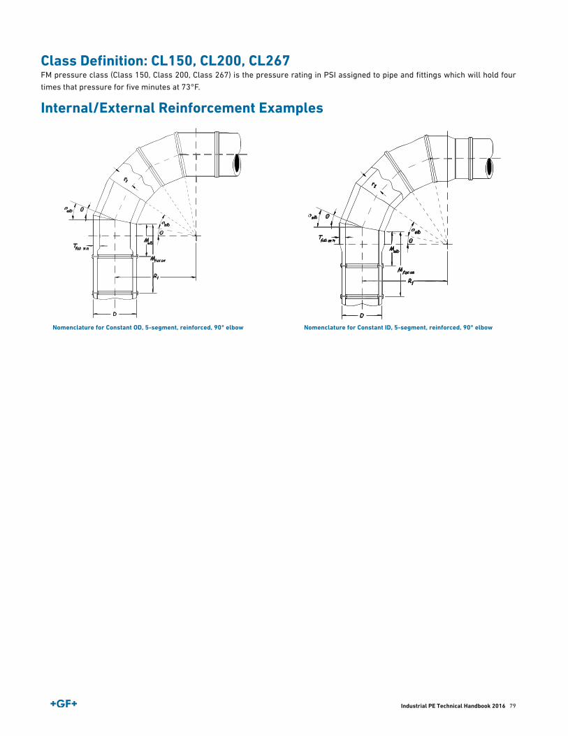
79Industrial PE Technical Handbook 2016
Class Definition: CL150, CL200, CL267FM pressure class (Class 150, Class 200, Class 267) is the pressure rating in PSI assigned to pipe and fittings which will hold four
times that pressure for five minutes at 73°F .
Internal/External Reinforcement Examples
Nomenclature for Constant ID, 5-segment, reinforced, 90° elbowNomenclature for Constant OD, 5-segment, reinforced, 90° elbow
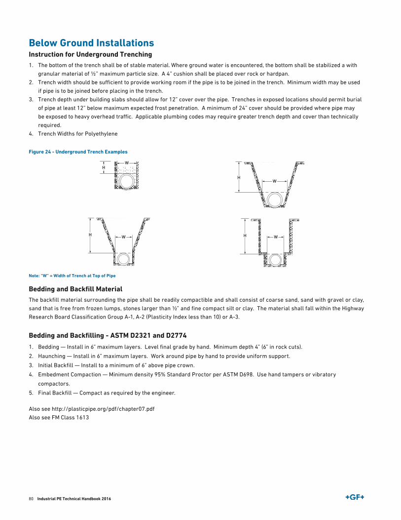
80 Industrial PE Technical Handbook 2016
Below Ground InstallationsInstruction for Underground Trenching 1 . The bottom of the trench shall be of stable material . Where ground water is encountered, the bottom shall be stabilized a with
granular material of ½” maximum particle size . A 4” cushion shall be placed over rock or hardpan .
2 . Trench width should be sufficient to provide working room if the pipe is to be joined in the trench . Minimum width may be used
if pipe is to be joined before placing in the trench .
3 . Trench depth under building slabs should allow for 12” cover over the pipe . Trenches in exposed locations should permit burial
of pipe at least 12” below maximum expected frost penetration . A minimum of 24” cover should be provided where pipe may
be exposed to heavy overhead traffic . Applicable plumbing codes may require greater trench depth and cover than technically
required .
4 . Trench Widths for Polyethylene
Figure 24 - Underground Trench Examples
HW
HW
H W WH
Note: “W” = Width of Trench at Top of Pipe
Bedding and Backfill MaterialThe backfill material surrounding the pipe shall be readily compactible and shall consist of coarse sand, sand with gravel or clay,
sand that is free from frozen lumps, stones larger than ½” and fine compact silt or clay . The material shall fall within the Highway
Research Board Classification Group A-1, A-2 (Plasticity Index less than 10) or A-3 .
Bedding and Backfilling - ASTM D2321 and D2774
1 . Bedding — Install in 6” maximum layers . Level final grade by hand . Minimum depth 4” (6” in rock cuts) .
2 . Haunching — Install in 6” maximum layers . Work around pipe by hand to provide uniform support .
3 . Initial Backfill — Install to a minimum of 6” above pipe crown .
4 . Embedment Compaction — Minimum density 95% Standard Proctor per ASTM D698 . Use hand tampers or vibratory
compactors .
5 . Final Backfill — Compact as required by the engineer .
Also see http://plasticpipe .org/pdf/chapter07 .pdf
Also see FM Class 1613
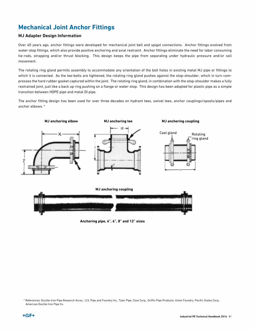
81Industrial PE Technical Handbook 2016
Mechanical Joint Anchor FittingsMJ Adapter Design Information
Over 40 years ago, anchor fittings were developed for mechanical joint bell and spigot connections . Anchor fittings evolved from
water-stop fittings, which also provide positive anchoring and axial restraint . Anchor fittings eliminate the need for labor consuming
tie-rods, strapping and/or thrust blocking . This design keeps the pipe from separating under hydraulic pressure and/or soil
movement .
The rotating ring gland permits assembly to accommodate any orientation of the bolt holes in existing metal MJ pipe or fittings to
which it is connected . As the tee-bolts are tightened, the rotating ring gland pushes against the stop-shoulder, which in turn com-
presses the hard rubber gasket captured within the joint . The rotating ring gland, in combination with the stop-shoulder makes a fully
restrained joint, just like a back up ring pushing on a flange or water-stop . This design has been adopted for plastic pipe as a simple
transition between HDPE pipe and metal DI pipe .
The anchor fitting design has been used for over three decades on hydrant tees, swivel tees, anchor couplings/spools/pipes and
anchor elbows . *
* References: Ductile-Iron Pipe Research Accoc ., U .S . Pipe and Foundry Inc ., Tyler Pipe, Clow Corp ., Griffin Pipe Products, Union Foundry, Pacific States Corp ., American Ductile Iron Pipe Co .
Cast gland Rotating ring gland
MJ anchoring elbow MJ anchoring tee MJ anchoring coupling
MJ anchoring coupling
Anchoring pipe, 4”, 6”, 8” and 12” sizes
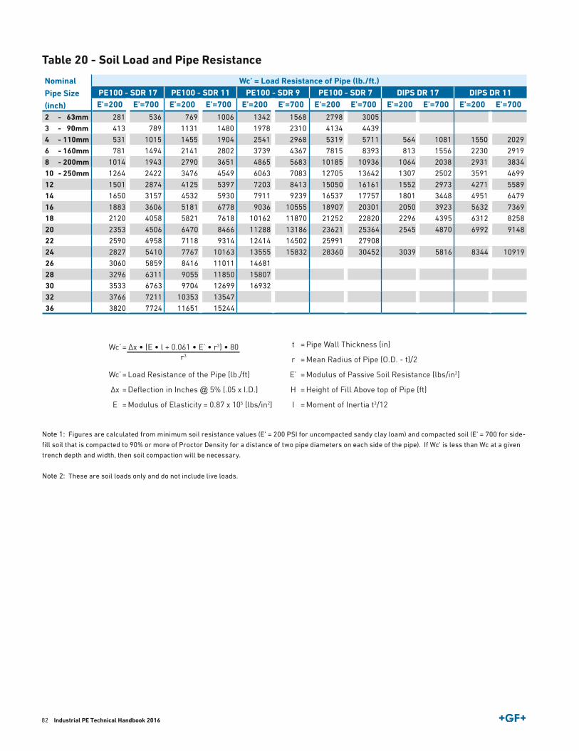
82 Industrial PE Technical Handbook 2016
Table 20 - Soil Load and Pipe Resistance
Nominal Pipe Size (inch)
Wc’ = Load Resistance of Pipe (lb./ft.)PE100 - SDR 17 PE100 - SDR 11 PE100 - SDR 9 PE100 - SDR 7 DIPS DR 17 DIPS DR 11E’=200 E’=700 E’=200 E’=700 E’=200 E’=700 E’=200 E’=700 E’=200 E’=700 E’=200 E’=700
2 - 63mm 281 536 769 1006 1342 1568 2798 3005
3 - 90mm 413 789 1131 1480 1978 2310 4134 4439
4 - 110mm 531 1015 1455 1904 2541 2968 5319 5711 564 1081 1550 2029
6 - 160mm 781 1494 2141 2802 3739 4367 7815 8393 813 1556 2230 2919
8 - 200mm 1014 1943 2790 3651 4865 5683 10185 10936 1064 2038 2931 3834
10 - 250mm 1264 2422 3476 4549 6063 7083 12705 13642 1307 2502 3591 4699
12 1501 2874 4125 5397 7203 8413 15050 16161 1552 2973 4271 5589
14 1650 3157 4532 5930 7911 9239 16537 17757 1801 3448 4951 6479
16 1883 3606 5181 6778 9036 10555 18907 20301 2050 3923 5632 7369
18 2120 4058 5821 7618 10162 11870 21252 22820 2296 4395 6312 8258
20 2353 4506 6470 8466 11288 13186 23621 25364 2545 4870 6992 9148
22 2590 4958 7118 9314 12414 14502 25991 27908
24 2827 5410 7767 10163 13555 15832 28360 30452 3039 5816 8344 10919
26 3060 5859 8416 11011 14681
28 3296 6311 9055 11850 15807
30 3533 6763 9704 12699 16932
32 3766 7211 10353 13547
36 3820 7724 11651 15244
Wc’
Δx
E
=
=
=
Load Resistance of the Pipe (lb./ft)
Deflection in Inches @ 5% (.05 x I.D.)
Modulus of Elasticity = 0.87 x 10⁵ (lbs/in2)
t
r
E’
H
I
=
=
=
=
=
Pipe Wall Thickness (in)
Mean Radius of Pipe (O.D. - t)/2
Modulus of Passive Soil Resistance (lbs/in2)
Height of Fill Above top of Pipe (ft)
Moment of Inertia t3/12
=Wc’ Δx • (E • l + 0.061 • E’ • r3) • 80r3
Note 1: Figures are calculated from minimum soil resistance values (E’ = 200 PSI for uncompacted sandy clay loam) and compacted soil (E’ = 700 for side-
fill soil that is compacted to 90% or more of Proctor Density for a distance of two pipe diameters on each side of the pipe) . If Wc’ is less than Wc at a given
trench depth and width, then soil compaction will be necessary .
Note 2: These are soil loads only and do not include live loads .
83Industrial PE Technical Handbook 2016
System Specification - ecoFIT Piping Systems Metric Polyethylene (PE)
1.0 ScopeThis specification covers the requirements for the Georg Fischer ecoFIT (PE) Metric and IPS Piping Systems intended for a wide range
of industrial applications including water, wastewater and effluent treatment as well as a wide range of chemical applications . The
components of the ecoFIT Metric and IPS (PE) piping system are in accordance with the following standards .
2.0 Basic System Data
2.1 Material Specification for ecoFIT (PE) Metric Pipe & FittingsA . All ecoFIT (PE) metric pipe shall be manufactured from PE100 and comply with a MRS class of 10 . Pipe manufactured
according to EN ISO 15494, DIN 8074 (dimensions) and DIN 8075 (quality specifications) as well as ASTM D3350 . The pipes
are NSF 61 approved . Pipe shall be manufactured to SDR 11 or SDR 17 dimensions with a pressure rating of 200 psi or
130 psi respectively when measured at 68°F . Pipe shall be supplied capped off at the extruder and supplied in 5 Meter
lengths .
B . All ecoFIT (PE) metric fittings and valves from Georg Fischer Piping Systems are manufactured according to ASTM D3350
from PE100 with a value of MRS 10 MPa, designed for 25 years operational life with water at 20°C . Fittings shall be
manufactured to SDR 11 or SDR 17 dimensions with a pressure rating of 200 psi or 130 psi respectively when measured
at 68°F . The material is designed for use with pressure bearing piping systems with long-term hydrostatic properties in
accordance with EN ISO 15494, as supplied by Georg Fischer Piping Systems .
3.0 Material Specification for ecoFIT (PE) Metric Ball Valves All valves shall be metric sizes manufactured by Georg Fischer Piping Systems or equal in accordance with EN ISO 16135, 16136,
16137, 16138, tested according to the same standard .
3.1 Ball Valves A . Ball valves consist of a valve body out of PP, ABS, or PVC combined with connection parts in PE .
3.1.1 Manual operated Ball Valves A . All ecoFIT (PE) ball valves with metric sizes d20mm – d110mm, shall be Georg Fischer Piping Systems Type 546, 543,
523 with true double union design manufactured by Georg Fischer Piping Systems in accordance with EN ISO 16135 .
Incorporated into its design shall be a safety stem with a predetermined breaking point above the bottom O-ring, preventing
any media leaking in the event of damage . The valve nut threads shall be buttress type to allow fast and safe radial mounting
and dismounting of the valve during installation or maintenance work . Seats shall be PTFE with backing rings creating self-
adjusting seals and constant operating torque . Backing rings and seals shall be EPDM or FPM . The handle shall include in
its design an integrated tool for removal of the union bush . Union bushes shall have left-hand threads to prevent possible
unscrewing when threaded end connectors are removed from pipe .
3.1.2 Ball Valve Accessories
A . A Multi-Functional Model (MFM) in PPGF equipped with internal limit switches for reliable electrical position feedback, is
mounted directly between the valve body and the valve handle . This MFM is also the necessary interface for later mounting
of actuators .
B . Mounting plate in PPGF with integrated inserts for mounting on any support
C . Lockable multi-functional handle
Section 4: Metric
84 Industrial PE Technical Handbook 2016
3.1.3 Electrically Actuated Ball Valves A . Electric actuators shall be Types EA11 (sizes DN10-50), EA21 (sizes DN10-50), EA31 (sizes DN65-100) shall be available
manufactured by Georg Fischer Piping Systems in accordance with EN 61010-1, EC directives 2004/108/EC (EMC) and
2006/95/EC, LVD and needs to be CE marked . Actuator housing shall be made of PPGF (polypropylene glass fiber reinforced),
flame retardant with external stainless steel screws . All electric actuators shall have an integrated emergency manual
override and integrated optical position indication . All electric actuator types (with the exception of EA11) shall have the
following accessories available:
• Fail-safe unit
• Heating element
• Cycle extension, cycle time monitoring, and cycle counting
• Motor current monitoring
• Position signalization
• Positioner Type PE25
• Limit switch kits Ag-Ni, Au, NPN, PNP, NAMUR
• AS Interface Plug Module
3.1.4 Pneumatically Actuated Ball Valves
A . Pneumatic actuators shall be Georg Fischer Piping Systems Types PA11 (for valve sizes d20-32mm) and PA21 (for valve
sizes d40-63mm) . They shall be manufactured by Georg Fischer Piping Systems . Pneumatic actuators shall be available as
fail safe close, fail safe open and double acting and have an integrated optical position indication . Actuator housing shall
be made of Polypropylene fiber glass reinforced (PPGF) and flame retardant . Actuators shall contain a pre-loaded spring
assembly to ensure safe actuator operation and maintenance . Actuators shall contain integrated Namur interface for the
easy mounting of positioners, limit switches and accessories . The valve shall be equipped optionally with a Multi-functional-
module for reliable electric feedback, mounted directly between the valve body and the actuator as manufactured by Georg
Fischer Piping Systems .
• For valve size d75mm pneumatic actuators shall be Type PA 30 (fail safe to close or open function), Type PA35 (double
acting function) .
• For valve size d90mm pneumatic actuators shall be Type PA 35 (fail safe to close or open function), Type PA40 (double
acting function) .
• For valve size d110 mm pneumatic actuators shall be Type PA 45 (fail safe to close or open function), Type PA45 (double
acting function)
B . Pneumatic actuators shall have an integrated optical position indicator . Actuator housing shall be made of hardened
anodized aluminum . Actuators shall contain integrated Namur interface for the easy mounting of positioners, limit switches
and accessories .
C . All pneumatically actuated ball valves shall have the following accessories available:
• Pilot valve remote or direct mounted in voltages 24VDC/AC, 110VAC, 230VAC
• Positioner Type DSR 500-3
• Limit switch kits Ag-Ni, Au, NPN, PNP
• Stroke limiter
• Manual override for all sizes up to d110
• AS Interface control module with incorporated position feedback and a solenoid pilot valve
3.2 Material Specification for ecoFIT (PE) Metric Diaphragm ValvesDiaphragm valves consist of valve body out of PP-H, ABS, or PVC combined with connection parts in PE .
3.2.1 Manual Diaphragm Valves
3.2.1.1 Diaphragm Valves d20mm to d63mm
A . All ecoFIT (PE) diaphragm valves, metric sized from d20mm to d63mm, shall be either:
• Type 514 (true double union design)
• Type 517 (flange design)
85Industrial PE Technical Handbook 2016
B . All diaphragm Valves shall be manufactured by Georg Fischer Piping Systems in accordance with EN ISO 16138 . The upper
body shall be PPGF (polypropylene glass fiber reinforced) connected to the lower body with a central union avoiding exposed
screws .
C . A two colored position indicator integrated into the hand wheel must be present to determine diaphragm position . The
hand wheel shall have an integrated locking mechanism . Diaphragms are to be EPDM, FPM, NBR, PTFE with EPDM or FPM
supporting diaphragm . Following options shall be available:
• Electrical feedback unit with either Ag-Ni or AU contacts
• Pressure proof housing
3.2.1.2 Diaphragm Valves d75mm to d160mm
A . All ecoFIT (PE) diaphragm valves, metric sized, shall be Type 317 (flanged design) consisting of valve body out of PP-H
or PVC-U with integrated fixed flange . All diaphragm valves shall be manufactured by Georg Fischer Piping Systems in
accordance with EN ISO 16138 . The upper body shall be PPGF (polypropylene glass fiber reinforced) connected to the lower
body with exposed stainless steel bolts . A position indicator integrated into the hand wheel must be present to determine
diaphragm position . Diaphragms are to be EPDM, FPM, NBR, or PTFE with EPDM or FPM supporting diaphragm .
3.2.2 Pneumatic Diaphragm Valves
3.2.2.1 Pneumatic Diaphragm Valves d20mm to d63mm
A . All ecoFIT (PE) diaphragm Valves, metric sized from d20mm to d63mm, shall be either:
• Type 514: true double union design
• Type 517: flange design
B . All diaphragm Valves shall be manufactured by Georg Fischer Piping Systems in accordance with EN ISO 16138 . The upper
body shall be connected to the lower body with a central union avoiding exposed screws .
C . Diaphragms have to be EPDM, FPM, NBR, PTFE with EPDM or FOM supporting diaphragm .
D . The mode of operation shall be fail safe close (FC), fail safe open (FO) and double acting (DA) . The valves shall have an
integrated optical position indicator . Actuator housing shall be made of PPGF (polypropylene glass fiber reinforced) .
Actuators with FC mode shall contain a pre-loaded galvanized steel spring assembly to ensure safe actuator operation and
maintenance . The actuator DIASTAR Ten, DIASTAR Ten Plus and DIASTAR Sixteen shall have following accessories available:
• Solenoid pilot valve remote or direct mounted in voltages 24VDC/AC, 110VAC, 230VAC
• Positioner Type DSR 500-1
• Feedback with following limit switches Ag-Ni, Au, NPN, PNP, NAMUR
• Stroke limiter & emergency manual override
• ASI controller
3.2.2.2 Pneumatic Diaphragm Valves d75mm to d160mm
A . All ecoFIT (PE) diaphragm valves, metric sized, shall be flanged design consisting of valve body out of PP-H, ABS or PVC
with integrated fixed flange .
B . All diaphragm valves shall be manufactured by Georg Fischer Piping Systems in accordance with EN ISO 16138 . The upper
body shall be connected to the lower body with exposed stainless steel bolts . Diaphragms are to be EPDM, FPM, NBR, or
PTFE with EPDM or FPM supporting diaphragm .
C . Pneumatic diaphragm actuators shall be Georg Fischer Piping Systems Type DIASTAR Type 025 . The mode of operation
shall be fail safe close (FC), fail safe open (FO) and double acting (DA) . The valves shall have an integrated optical position
indicator . Actuator housing shall be made of PPGF (polypropylene glass fiber reinforced
D . Actuators with FC mode shall contain a pre-loaded galvanized steel spring assembly to ensure safe actuator operation and
maintenance . The actuator DIASTAR 025 shall have following accessories available:
• Solenoid pilot valve remote or direct mounted in voltages 24VDC/AC, 110VAC, 230VAC
• Positioner Type DSR 500-2
• Feedback with following limit switches Ag-Ni, Au, NPN, PNP, NAMUR
• Stroke limiter & emergency manual override
• ASI Controller
86 Industrial PE Technical Handbook 2016
3.3 Butterfly Valves
3.3.1 Plastic Butterfly ValvesA . Butterfly valves suitable for the ecoFIT (PE) System of Georg Fischer Piping Systems are made from PP-H or PVC Material .
B . All butterfly valves, metric sizes 2” (d63mm) – 10” (d250mm), shall be Georg Fischer Piping Systems Type 567/568/563
wafer/lug type with a double eccentric disc design manufactured by Georg Fischer Piping Systems in accordance with EN ISO
16136 . Seals shall be available in EPDM, FPM and PTFE/FPM . The lever handle shall be lockable in increments of 5 degrees .
There shall always be six teeth engaged between the ratchet and the index plate to ensure accurate and safe positioning
of the lever . There shall be the option of fine adjustment by use of a specific hand lever, allowing the disc to be exposed
at any angle between 0° and 90° . As an option, the hand lever shall be lockable . The hand lever shall be manufactured of
high strength PPGF (polypropylene glass fiber reinforced) . The option of an integrated electric position indicator shall be
available . As an option the valves can be actuated by gear box with hand wheel . The electric position indicator shall be
integrated into the mounting flange . Butterfly valves shall have low actuation torque to enable easy operation . All butterfly
valves Type 567/568 manufactured by Georg Fischer Piping Systems are designed for a nominal pressure rate of 10 bar . All
butterfly valves Type 563 are designed for a nominal pressure rate of 4 bar .
3.3.1.1 Electrically Actuated Butterfly ValvesA . Electric actuators shall be Georg Fischer Piping Systems Types EA31 or EA42 dependent on valve size . They shall be
manufactured by Georg Fischer Piping Systems in accordance with EN 61010-1, as per the above specifications . Actuator
housing shall be made of PPGF (polypropylene glass fiber reinforced), flame retardant and feature external stainless steel
screws . All electric actuators shall have an integrated emergency manual override and integrated optical position indication .
B . All electric actuator types shall have the following accessories available:
• Fail-safe unit
• Heating element
• Cycle extension, monitoring, and counting
• Motor current monitoring
• Position signalization
• Positioner Type PE25
• Limit switch kits Ag-Ni, Au, NPN, PNP
• Manual override
• AS-Interface Plug Module
3.3.1.2 Pneumatically Actuated Butterfly Valves
A . Pneumatic actuators shall be Georg Fischer Piping Systems Types PA 35 (metric sizes d63-75mm), PA40 (metric size
d90mm only), PA45 (metric size d110mm), PA55 (metric size d160mm), PA60 (metric sizes d225mm FC), PA65 . They shall
be supplied by Georg Fischer Piping Systems . Pneumatic actuators shall be available as fail safe close, fail safe open and
double acting and have an integrated optical position indication . Actuator housing shall be made of hardened anodized
aluminum . Actuators shall contain integrated Namur interfaces for the easy mounting of positioners, limit switches and
accessories . All pneumatically actuated butterfly valves shall have the following accessories available:
• Solenoid pilot valve remote or direct mounted in voltages 24VDC/AC, 110VAC, 230VAC
• Positioner Type DSR 500-3
• Feedback with following limit switches Ag-Ni, Au, NPN, PNP, NAMUR
• Stroke limiter & emergency manual override
• ASI-controller
3.4 Material Specification for ecoFIT (PE) Metric Check Valves
A . Check valves consist of valve body out of PP-H, ABS, or PVC combined with connection parts in PE or flanged .
B . All cone check valves, according to EN ISO 16137, metric sizes d20-d110mm metric, shall be Type 561/562 true double
union design . Seals shall be EPDM or FPM . Union bushes shall have a left hand thread to prevent possible unscrewing
when threaded end connectors are removed from pipe . This valve shall be suitable for mounting in a vertical and
horizontal position . Type 562 shall be equipped with a spring made of stainless steel (V2A, Nimonic, halar coated) to allow
position independent installation . The valves are designed for a nominal pressure of 16 bar .
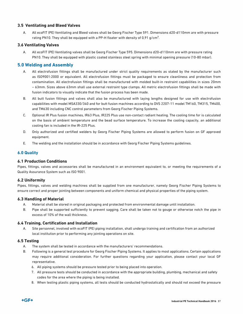
87Industrial PE Technical Handbook 2016
3.5 Ventilating and Bleed Valves
A . All ecoFIT (PE) Ventilating and Bleed valves shall be Georg Fischer Type 591 . Dimensions d20-d110mm are with pressure
rating PN10 . They shall be equipped with a PP-H floater with density of 0,91 g/cm³ .
3.6 Ventilating Valves
A . All ecoFIT (PE) Ventilating valves shall be Georg Fischer Type 595 . Dimensions d20-d110mm are with pressure rating
PN10 . They shall be equipped with plastic coated stainless steel spring with minimal opening pressure (10-80 mbar) .
5.0 Welding and Assembly A . All electrofusion fittings shall be manufactured under strict quality requirements as stated by the manufacturer such
as ISO9001:2000 or equivalent . All electrofusion fittings must be packaged to ensure cleanliness and protection from
contamination . All electrofusion fittings shall be manufactured with molded built-in restraint capabilities in sizes 20mm
– 63mm . Sizes above 63mm shall use external restraint type clamps . All metric electrofusion fittings shall be made with
fusion indicators to visually indicate that the fusion process has been made .
B . All butt fusion fittings and valves shall also be manufactured with laying lengths designed for use with electrofusion
capabilities with model MSA330/340 and for butt fusion machines according to DVS 2207-11 model TM160, TM315, TM400,
and TM630 including CNC control parameters from Georg Fischer Piping Systems .
C . Optional IR Plus fusion machines, IR63 Plus, IR225 Plus use non-contact radiant heating . The cooling time for is calculated
on the basis of ambient temperature and the bead surface temperature . To increase the cooling capacity, an additional
cooling fan is included in the IR-225 Plus .
D . Only authorized and certified welders by Georg Fischer Piping Systems are allowed to perform fusion on GF approved
equipment .
E . The welding and the installation should be in accordance with Georg Fischer Piping Systems guidelines .
6.0 Quality
6.1 Production Conditions Pipes, fittings, valves and accessories shall be manufactured in an environment equivalent to, or meeting the requirements of a
Quality Assurance System such as ISO 9001 .
6.2 UniformityPipes, fittings, valves and welding machines shall be supplied from one manufacturer, namely Georg Fischer Piping Systems to
ensure correct and proper jointing between components and uniform chemical and physical properties of the piping system .
6.3 Handling of MaterialA . Material shall be stored in original packaging and protected from environmental damage until installation .
B . Pipe shall be supported sufficiently to prevent sagging . Care shall be taken not to gouge or otherwise notch the pipe in
excess of 10% of the wall thickness .
6.4 Training, Certification and Installation A . Site personnel, involved with ecoFIT (PE) piping installation, shall undergo training and certification from an authorized
local institution prior to performing any jointing operations on site .
6.5 TestingA . The system shall be tested in accordance with the manufacturers’ recommendations .
B . Following is a general test procedure for Georg Fischer Piping Systems . It applies to most applications . Certain applications
may require additional consideration . For further questions regarding your application, please contact your local GF
representative .
6 . All piping systems should be pressure tested prior to being placed into operation .
7 . All pressure tests should be conducted in accordance with the appropriate building, plumbing, mechanical and safety
codes for the area where the piping is being installed .
8 . When testing plastic piping systems, all tests should be conducted hydrostatically and should not exceed the pressure
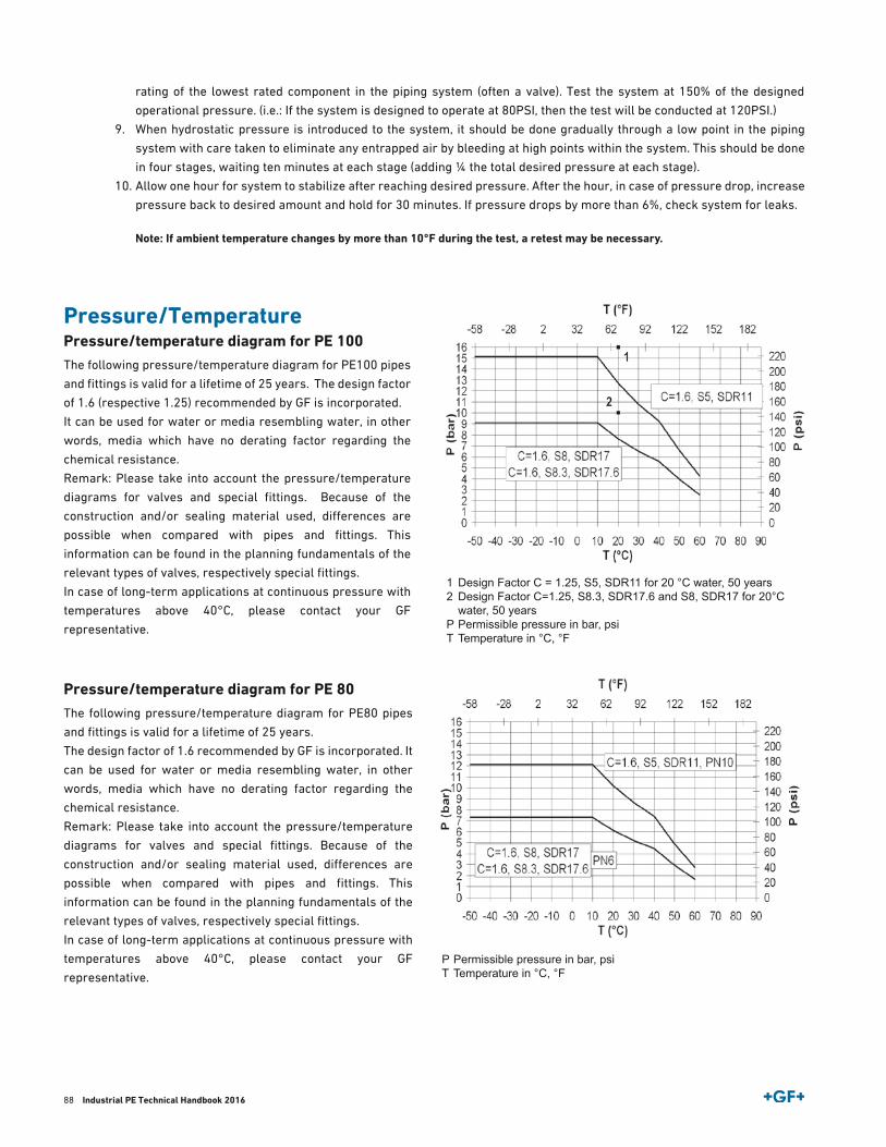
88 Industrial PE Technical Handbook 2016
rating of the lowest rated component in the piping system (often a valve) . Test the system at 150% of the designed
operational pressure . (i .e .: If the system is designed to operate at 80PSI, then the test will be conducted at 120PSI .)
9 . When hydrostatic pressure is introduced to the system, it should be done gradually through a low point in the piping
system with care taken to eliminate any entrapped air by bleeding at high points within the system . This should be done
in four stages, waiting ten minutes at each stage (adding ¼ the total desired pressure at each stage) .
10 . Allow one hour for system to stabilize after reaching desired pressure . After the hour, in case of pressure drop, increase
pressure back to desired amount and hold for 30 minutes . If pressure drops by more than 6%, check system for leaks .
Note: If ambient temperature changes by more than 10°F during the test, a retest may be necessary.
Pressure/TemperaturePressure/temperature diagram for PE 100The following pressure/temperature diagram for PE100 pipes
and fittings is valid for a lifetime of 25 years . The design factor
of 1 .6 (respective 1 .25) recommended by GF is incorporated .
It can be used for water or media resembling water, in other
words, media which have no derating factor regarding the
chemical resistance .
Remark: Please take into account the pressure/temperature
diagrams for valves and special fittings . Because of the
construction and/or sealing material used, differences are
possible when compared with pipes and fittings . This
information can be found in the planning fundamentals of the
relevant types of valves, respectively special fittings .
In case of long-term applications at continuous pressure with
temperatures above 40°C, please contact your GF
representative .
Pressure/temperature diagram for PE 80The following pressure/temperature diagram for PE80 pipes
and fittings is valid for a lifetime of 25 years .
The design factor of 1 .6 recommended by GF is incorporated . It
can be used for water or media resembling water, in other
words, media which have no derating factor regarding the
chemical resistance .
Remark: Please take into account the pressure/temperature
diagrams for valves and special fittings . Because of the
construction and/or sealing material used, differences are
possible when compared with pipes and fittings . This
information can be found in the planning fundamentals of the
relevant types of valves, respectively special fittings .
In case of long-term applications at continuous pressure with
temperatures above 40°C, please contact your GF
representative .
Pressure/temperature diagram for PEPE 100The following pressure/temperature diagram for PE100 pipes and fittings is valid for a lifetime of 25 years.
The design factor of 1.6 (respective 1.25) recommen-ded by GF is incorporated.
It can be used for water or media resembling water, inother words, media which have no derating factor regarding the chemical resistance.
Remark: Please take into account the pressure/temperature diagrams for valves and special fittings. Because of the construction and/or sealing material used, differences are possible when compared with pipes and fittings. This information can be found in the planning fundamentals of the relevant types of valves, respectivelyspecial fittings.
In case of long-term applications at continuous pressure with temperatures above 40 °C, please contact your GF representative.
Polyethylene PE 100 – the third Generation of polyethylene
1 Design Factor C = 1.25, S5, SDR11 for 20 °C water, 50 years2 Design Factor C=1.25, S8.3, SDR17.6 and S8, SDR17 for 20°C water, 50 yearsP Permissible pressure in bar, psiT Temperature in °C, °F
Pressure/temperature diagram for PEPE 80The following pressure/temperature diagram for PE80 pipes and fittings is valid for a lifetime of 25 years.
The design factor of 1.6 recommended by GF is incorporated.
It can be used for water or media resembling water, inother words, media which have no derating factor re-garding the chemical resistance.
Remark: Please take into account the pressure/temperature diagrams for valves and special fittings. Becauseof the construction and/or sealing material used, differences are possible when compared with pipes and fittings. This information can be found in the planning fundamentals of the relevant types of valves, respectively special fittings.
In case of long-term applications at continuous pressure with temperatures above 40 °C please contact your GF representative.
P Permissible pressure in bar, psiT Temperature in °C, °F
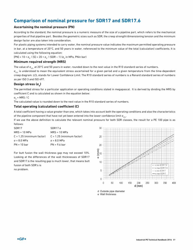
89Industrial PE Technical Handbook 2016
Ascertaining the nominal pressure (PN)According to the standard, the nominal pressure is a numeric measure of the size of a pipeline part, which refers to the mechanical properties of that pipeline part. Besides the geometric sizes such as SDR, the creep strength/dimensioning tension and the minimum design factor are also taken into consideration.
For plastic piping systems intended to carry water, the nominal pressure value indicates the maximum permit-ted operating pressure in bar, at a temperature of 20°C, and 50 years in water, referenced to the minimum value of the total (calculation) coefficients. It is calculated using the following equation:
[PN] = 10 • σS / [S] = 20 • σS / (SDR – 1) (σs in MPa, PNin bar)
Minimum required strength (MRS):The value of σLCL at 20°C and 50 years in water, roun-ded down to the next value in the R10 standard series of numbers.
σLCL is understood to mean the equivalent stress ascertained for a given period and a given temperature fromthe time-dependent creep diagram. LCL stands for Lower Confidence Limit. The R10 standard series of numbers is a Renard standard series of numbers as per ISO 3 and ISO 497.
Design stress (σ S):The permitted stress for a particular application or operating conditions stated in megapascal. It is derived by dividing the MRS by coefficient C and is calculated as shown in the equation below:
σS = MRS / C
The calculated value is rounded down to the next value in the R10 standard series of numbers.
Total operating (calculation) coefficient (C):A total coefficient having a value greater than one, which takes into account both the operating condtions and also the characteristics of the pipeline component that have not yet been entered into the lower confi-dence limit σLCL.
If we use the above definition to calculate the relevant nominal pressure for both SDR classes, the result for a PE 100 pipe is as follows:
SDR17 SDR17.6 MRS = 10 MPa MRS = 10 MPaC = 1.25 (minimum factor) C = 1.25 (minimum factor)σ = 8.0 MPa σ = 8.0 MPaPN = 10 bar PN = 9.6 bar
Comparison of nominal pressure for SDR17and SDR17.6
d Outside pipe diametere Wall thickness
The above definitions thus produce a difference of 0.4 bar in PN, but in actual practice this does not matter, as shown below:
1.) Industrial pipelines are normally designed for a ser-vice life of 25 years. If from the time-dependent creep diagrams we ascertain for ELTEX TUB 121 or CRP 100 an equivalent stress of σLCL for the operating point of 25 years and 20°C, we obtain a tension of 10.6 MPa (minimum value of both PE100 materials as per manufacturer‘s data).
2.) If we use this tension to ascertain the dimensioning tension σS, and do not round it down, we obtain the value of 8.48 MPa.
3.) Thus the actual nominal pressure in practice is:
for SDR 17 => PN = 10.6 bar and forSDR 17.6 => PN = 10.2 bar.
To summarise: Both SDR classes comply with requirements for industrial applications mentioning a PN10 system.Comparison of geometric dimensionsThe two SDR classes differ only slightly in wall thick-ness, as can be seen from the diagram below. This shows that there is an area where the wall thickness complies with both requirements of both SDR classes.
For butt fusion the wall thickness gap may notex-ceed 10 %. Looking at the differences of the wallthick-nesses of SDR17 and SDR17.6 the resulting gap ismuch lower, that means butt fusion of both SDR‘s is noproblem.
Comparison of nominal pressure for SDR17 and SDR17.6Ascertaining the nominal pressure (PN)According to the standard, the nominal pressure is a numeric measure of the size of a pipeline part, which refers to the mechanical
properties of that pipeline part . Besides the geometric sizes such as SDR, the creep strength/dimensioning tension and the minimum
design factor are also taken into consideration .
For plastic piping systems intended to carry water, the nominal pressure value indicates the maximum permitted operating pressure
in bar, at a temperature of 20°C, and 50 years in water, referenced to the minimum value of the total (calculation) coefficients . It is
calculated using the following equation:
[PN] = 10 • σS / [S] = 20 • σ
S / (SDR – 1) (σ
S in MPa, PNin bar)
Minimum required strength (MRS)The value of σ
LCL at 20°C and 50 years in water, rounded down to the next value in the R10 standard series of numbers .
σLCL
is understood to mean the equivalent stress ascertained for a given period and a given temperature from the time-dependent
creep diagram . LCL stands for Lower Confidence Limit . The R10 standard series of numbers is a Renard standard series of numbers
as per ISO 3 and ISO 497 .
Design stress (σS)The permitted stress for a particular application or operating conditions stated in megapascal . It is derived by dividing the MRS by
coefficient C and is calculated as shown in the equation below:
σS = MRS / C
The calculated value is rounded down to the next value in the R10 standard series of numbers .
Total operating (calculation) coefficient (C)A total coefficient having a value greater than one, which takes into account both the operating conditions and also the characteristics
of the pipeline component that have not yet been entered into the lower confidence limit σLCL
.
If we use the above definition to calculate the relevant nominal pressure for both SDR classes, the result for a PE 100 pipe is as
follows:
SDR17 SDR17 .6
MRS = 10 MPa MRS = 10 MPa
C = 1 .25 (minimum factor) C = 1 .25 (minimum factor)
σ = 8 .0 MPa σ = 8 .0 MPa
PN = 10 bar PN = 9 .6 bar
For butt fusion the wall thickness gap may not exceed 10% .
Looking at the differences of the wall thicknesses of SDR17
and SDR17 .6 the resulting gap is much lower, that means butt
fusion of both SDR‘s is
no problem .
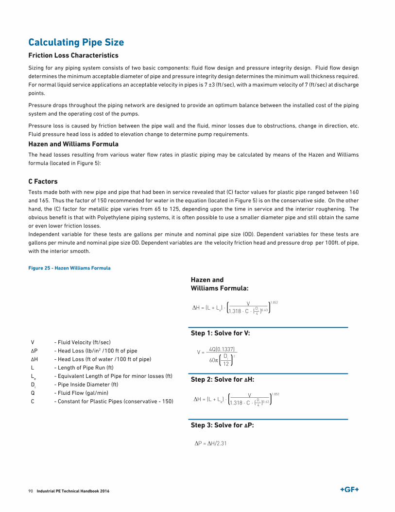
90 Industrial PE Technical Handbook 2016
Calculating Pipe SizeFriction Loss Characteristics
Sizing for any piping system consists of two basic components: fluid flow design and pressure integrity design . Fluid flow design
determines the minimum acceptable diameter of pipe and pressure integrity design determines the minimum wall thickness required .
For normal liquid service applications an acceptable velocity in pipes is 7 ±3 (ft/sec), with a maximum velocity of 7 (ft/sec) at discharge
points .
Pressure drops throughout the piping network are designed to provide an optimum balance between the installed cost of the piping
system and the operating cost of the pumps .
Pressure loss is caused by friction between the pipe wall and the fluid, minor losses due to obstructions, change in direction, etc .
Fluid pressure head loss is added to elevation change to determine pump requirements .
Hazen and Williams FormulaThe head losses resulting from various water flow rates in plastic piping may be calculated by means of the Hazen and Williams
formula (located in Figure 5):
C FactorsTests made both with new pipe and pipe that had been in service revealed that (C) factor values for plastic pipe ranged between 160
and 165 . Thus the factor of 150 recommended for water in the equation (located in Figure 5) is on the conservative side . On the other
hand, the (C) factor for metallic pipe varies from 65 to 125, depending upon the time in service and the interior roughening . The
obvious benefit is that with Polyethylene piping systems, it is often possible to use a smaller diameter pipe and still obtain the same
or even lower friction losses .
Independent variable for these tests are gallons per minute and nominal pipe size (OD) . Dependent variables for these tests are
gallons per minute and nominal pipe size OD . Dependent variables are the velocity friction head and pressure drop per 100ft . of pipe,
with the interior smooth .
Figure 25 - Hazen Williams Formula
V - Fluid Velocity (ft/sec)
∆P - Head Loss (lb/in2 /100 ft of pipe
∆H - Head Loss (ft of water /100 ft of pipe)
L - Length of Pipe Run (ft)
Le - Equivalent Length of Pipe for minor losses (ft)
Di - Pipe Inside Diameter (ft)
Q - Fluid Flow (gal/min)
C - Constant for Plastic Pipes (conservative - 150)
Hazen and Williams Formula:
V = 4Q(0.1337)
( Di
12
2)60
ΔP = ΔH/2.31
ΔH = (L + Le) · V
1.318 · C · ( )0.63Di
4
1.852
( )
Step 1: Solve for V:
V = 4Q(0.1337)
( Di
12
2)60
ΔP = ΔH/2.31
ΔH = (L + Le) · V
1.318 · C · ( )0.63Di
4
1.852
( )Step 2: Solve for ∆H:
V = 4Q(0.1337)
( Di
12
2)60
ΔP = ΔH/2.31
ΔH = (L + Le) · V
1.318 · C · ( )0.63Di
4
1.852
( )
Step 3: Solve for ∆P:
V = 4Q(0.1337)
( Di
12
2)60
ΔP = ΔH/2.31
ΔH = (L + Le) · V
1.318 · C · ( )0.63Di
4
1.852
( )
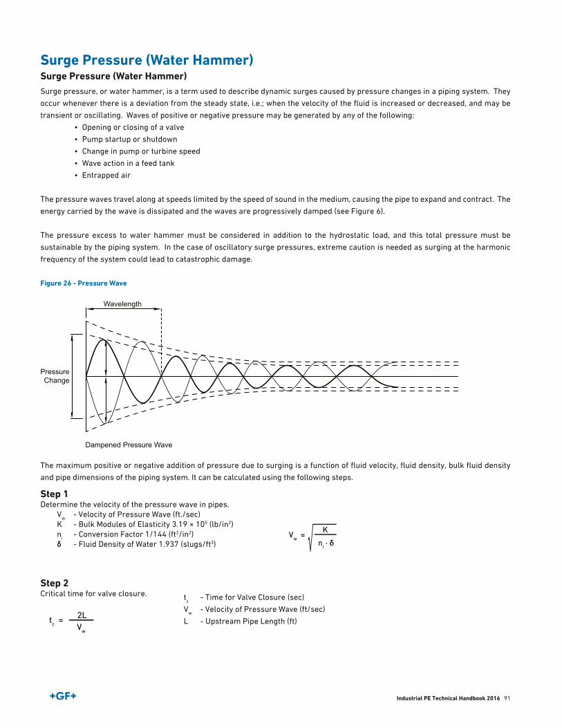
91Industrial PE Technical Handbook 2016
Surge Pressure (Water Hammer)Surge Pressure (Water Hammer)Surge pressure, or water hammer, is a term used to describe dynamic surges caused by pressure changes in a piping system . They
occur whenever there is a deviation from the steady state, i .e .; when the velocity of the fluid is increased or decreased, and may be
transient or oscillating . Waves of positive or negative pressure may be generated by any of the following:
• Opening or closing of a valve
• Pump startup or shutdown
• Change in pump or turbine speed
• Wave action in a feed tank
• Entrapped air
The pressure waves travel along at speeds limited by the speed of sound in the medium, causing the pipe to expand and contract . The
energy carried by the wave is dissipated and the waves are progressively damped (see Figure 6) .
The pressure excess to water hammer must be considered in addition to the hydrostatic load, and this total pressure must be
sustainable by the piping system . In the case of oscillatory surge pressures, extreme caution is needed as surging at the harmonic
frequency of the system could lead to catastrophic damage .
Figure 26 - Pressure Wave
PressureChange
Wavelength
Dampened Pressure Wave
The maximum positive or negative addition of pressure due to surging is a function of fluid velocity, fluid density, bulk fluid density
and pipe dimensions of the piping system . It can be calculated using the following steps .
Step 1Determine the velocity of the pressure wave in pipes . V
w - Velocity of Pressure Wave (ft ./sec)
K - Bulk Modules of Elasticity 3 .19 × 105 (lb/in2) n
i - Conversion Factor 1/144 (ft2/in2)
δ - Fluid Density of Water 1 .937 (slugs/ft3)Vw =
K
ni · δ √ 3.19 x 105
· 1.937 √ 1144
Vw = Vw = 4870 (ft/sec)
STEP 1:
STEP 2:
STEP 3:
tc =2LVw
Pg =2 · δ · L · V · ni
tv
tc =2 · 5004870
tc = 0.2 (sec)
Pi = δ · V · Vw ni Pi =1.937 · 4 · 4870
144Pi = 262 (lb/in2)
STEP 4:
STEP 5:
Pmax = Pi + Ps Pmax = 262 + 50 Pmax = 312 (lb/in2)
Pg =2 · 1.937 · 500 · 4 ·
2Pg = 26.9 (lb/in2)
1144
Pmax = Pg + Ps Pmax = 26.9 + 50 = 76.9 (lb/in2)
Step 2Critical time for valve closure .
Vw =K
ni · δ √ 3.19 x 105
· 1.937 √ 1144
Vw = Vw = 4870 (ft/sec)
STEP 1:
STEP 2:
STEP 3:
tc =2LVw
Pg =2 · δ · L · V · ni
tv
tc =2 · 5004870
tc = 0.2 (sec)
Pi = δ · V · Vw ni Pi =1.937 · 4 · 4870
144Pi = 262 (lb/in2)
STEP 4:
STEP 5:
Pmax = Pi + Ps Pmax = 262 + 50 Pmax = 312 (lb/in2)
Pg =2 · 1.937 · 500 · 4 ·
2Pg = 26.9 (lb/in2)
1144
Pmax = Pg + Ps Pmax = 26.9 + 50 = 76.9 (lb/in2)
tc - Time for Valve Closure (sec)
Vw - Velocity of Pressure Wave (ft/sec)
L - Upstream Pipe Length (ft)
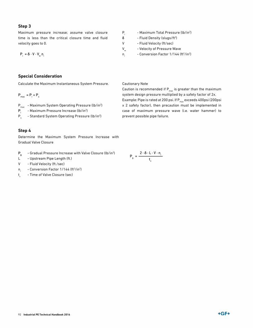
92 Industrial PE Technical Handbook 2016
Step 3Maximum pressure increase; assume valve closure
time is less than the critical closure time and fluid
velocity goes to 0 .
Vw =K
ni · δ √ 3.19 x 105
· 1.937 √ 1144
Vw = Vw = 4870 (ft/sec)
STEP 1:
STEP 2:
STEP 3:
tc =2LVw
Pg =2 · δ · L · V · ni
tv
tc =2 · 5004870
tc = 0.2 (sec)
Pi = δ · V · Vw ni Pi =1.937 · 4 · 4870
144Pi = 262 (lb/in2)
STEP 4:
STEP 5:
Pmax = Pi + Ps Pmax = 262 + 50 Pmax = 312 (lb/in2)
Pg =2 · 1.937 · 500 · 4 ·
2Pg = 26.9 (lb/in2)
1144
Pmax = Pg + Ps Pmax = 26.9 + 50 = 76.9 (lb/in2)
Pi - Maximum Total Pressure (lb/in2)
δ - Fluid Density (slugs/ft3)
V - Fluid Velocity (ft/sec)
Vw - Velocity of Pressure Wave
ni - Conversion Factor 1/144 (ft2/in2)
Special Consideration
Calculate the Maximum Instantaneous System Pressure .
Vw =K
ni · δ √ 3.19 x 105
· 1.937 √ 1144
Vw = Vw = 4870 (ft/sec)
STEP 1:
STEP 2:
STEP 3:
tc =2LVw
Pg =2 · δ · L · V · ni
tv
tc =2 · 5004870
tc = 0.2 (sec)
Pi = δ · V · Vw ni Pi =1.937 · 4 · 4870
144Pi = 262 (lb/in2)
STEP 4:
STEP 5:
Pmax = Pi + Ps Pmax = 262 + 50 Pmax = 312 (lb/in2)
Pg =2 · 1.937 · 500 · 4 ·
2Pg = 26.9 (lb/in2)
1144
Pmax = Pg + Ps Pmax = 26.9 + 50 = 76.9 (lb/in2)
Pmax
- Maximum System Operating Pressure (lb/in2)
Pi - Maximum Pressure Increase (lb/in2)
Ps - Standard System Operating Pressure (lb/in2)
Cautionary Note
Caution is recommended if Pmax
is greater than the maximum
system design pressure multiplied by a safety factor of 2x .
Example: Pipe is rated at 200 psi . If Pmax
exceeds 400psi (200psi
x 2 safety factor), then precaution must be implemented in
case of maximum pressure wave (i .e . water hammer) to
prevent possible pipe failure .
Step 4Determine the Maximum System Pressure Increase with
Gradual Valve Closure
Pg - Gradual Pressure Increase with Valve Closure (lb/in2)
L - Upstream Pipe Length (ft .)
V - Fluid Velocity (ft ./sec)
ni - Conversion Factor 1/144 (ft2/in2)
tv - Time of Valve Closure (sec)
Vw =K
ni · δ √ 3.19 x 105
· 1.937 √ 1144
Vw = Vw = 4870 (ft/sec)
STEP 1:
STEP 2:
STEP 3:
tc =2LVw
Pg =2 · δ · L · V · ni
tv
tc =2 · 5004870
tc = 0.2 (sec)
Pi = δ · V · Vw ni Pi =1.937 · 4 · 4870
144Pi = 262 (lb/in2)
STEP 4:
STEP 5:
Pmax = Pi + Ps Pmax = 262 + 50 Pmax = 312 (lb/in2)
Pg =2 · 1.937 · 500 · 4 ·
2Pg = 26.9 (lb/in2)
1144
Pmax = Pg + Ps Pmax = 26.9 + 50 = 76.9 (lb/in2)
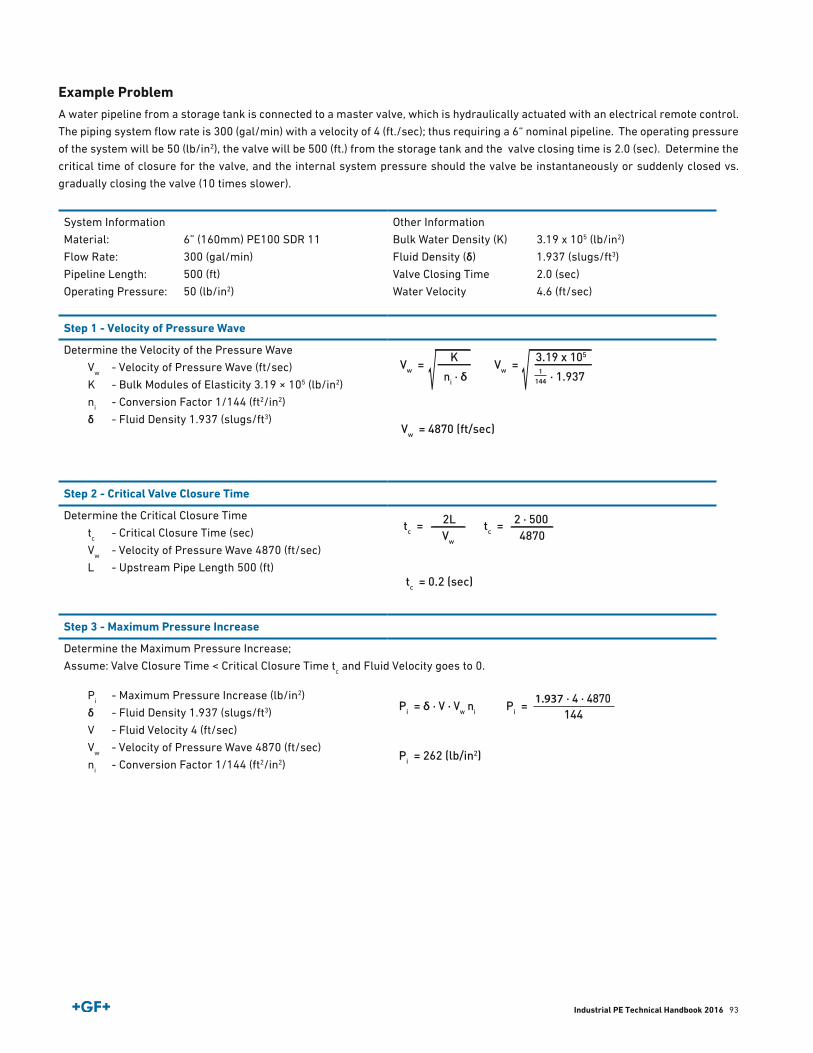
93Industrial PE Technical Handbook 2016
Example ProblemA water pipeline from a storage tank is connected to a master valve, which is hydraulically actuated with an electrical remote control .
The piping system flow rate is 300 (gal/min) with a velocity of 4 (ft ./sec); thus requiring a 6“ nominal pipeline . The operating pressure
of the system will be 50 (lb/in2), the valve will be 500 (ft .) from the storage tank and the valve closing time is 2 .0 (sec) . Determine the
critical time of closure for the valve, and the internal system pressure should the valve be instantaneously or suddenly closed vs .
gradually closing the valve (10 times slower) .
System Information
Material: 6” (160mm) PE100 SDR 11
Flow Rate: 300 (gal/min)
Pipeline Length: 500 (ft)
Operating Pressure: 50 (lb/in2)
Other Information
Bulk Water Density (K) 3 .19 x 105 (lb/in2)
Fluid Density (δ) 1 .937 (slugs/ft3)
Valve Closing Time 2 .0 (sec)
Water Velocity 4 .6 (ft/sec)
Step 1 - Velocity of Pressure Wave
Determine the Velocity of the Pressure Wave
Vw - Velocity of Pressure Wave (ft/sec)
K - Bulk Modules of Elasticity 3 .19 × 105 (lb/in2)
ni - Conversion Factor 1/144 (ft2/in2)
δ - Fluid Density 1 .937 (slugs/ft3)
Vw =K
ni · δ √ 3.19 x 105
· 1.937 √ 1144
Vw = Vw = 4870 (ft/sec)
STEP 1:
STEP 2:
STEP 3:
tc =2LVw
Pg =2 · δ · L · V · ni
tv
tc =2 · 5004870
tc = 0.2 (sec)
Pi = δ · V · Vw ni Pi =1.937 · 4 · 4870
144Pi = 262 (lb/in2)
STEP 4:
STEP 5:
Pmax = Pi + Ps Pmax = 262 + 50 Pmax = 312 (lb/in2)
Pg =2 · 1.937 · 500 · 4 ·
2Pg = 26.9 (lb/in2)
1144
Pmax = Pg + Ps Pmax = 26.9 + 50 = 76.9 (lb/in2)
Vw =K
ni · δ √ 3.19 x 105
· 1.937 √ 1144
Vw = Vw = 4870 (ft/sec)
STEP 1:
STEP 2:
STEP 3:
tc =2LVw
Pg =2 · δ · L · V · ni
tv
tc =2 · 5004870
tc = 0.2 (sec)
Pi = δ · V · Vw ni Pi =1.937 · 4 · 4870
144Pi = 262 (lb/in2)
STEP 4:
STEP 5:
Pmax = Pi + Ps Pmax = 262 + 50 Pmax = 312 (lb/in2)
Pg =2 · 1.937 · 500 · 4 ·
2Pg = 26.9 (lb/in2)
1144
Pmax = Pg + Ps Pmax = 26.9 + 50 = 76.9 (lb/in2)
Step 2 - Critical Valve Closure Time
Determine the Critical Closure Time
tc - Critical Closure Time (sec)
Vw - Velocity of Pressure Wave 4870 (ft/sec)
L - Upstream Pipe Length 500 (ft)
Vw =K
ni · δ √ 3.19 x 105
· 1.937 √ 1144
Vw = Vw = 4870 (ft/sec)
STEP 1:
STEP 2:
STEP 3:
tc =2LVw
Pg =2 · δ · L · V · ni
tv
tc =2 · 5004870
tc = 0.2 (sec)
Pi = δ · V · Vw ni Pi =1.937 · 4 · 4870
144Pi = 262 (lb/in2)
STEP 4:
STEP 5:
Pmax = Pi + Ps Pmax = 262 + 50 Pmax = 312 (lb/in2)
Pg =2 · 1.937 · 500 · 4 ·
2Pg = 26.9 (lb/in2)
1144
Pmax = Pg + Ps Pmax = 26.9 + 50 = 76.9 (lb/in2)
Vw =K
ni · δ √ 3.19 x 105
· 1.937 √ 1144
Vw = Vw = 4870 (ft/sec)
STEP 1:
STEP 2:
STEP 3:
tc =2LVw
Pg =2 · δ · L · V · ni
tv
tc =2 · 5004870
tc = 0.2 (sec)
Pi = δ · V · Vw ni Pi =1.937 · 4 · 4870
144Pi = 262 (lb/in2)
STEP 4:
STEP 5:
Pmax = Pi + Ps Pmax = 262 + 50 Pmax = 312 (lb/in2)
Pg =2 · 1.937 · 500 · 4 ·
2Pg = 26.9 (lb/in2)
1144
Pmax = Pg + Ps Pmax = 26.9 + 50 = 76.9 (lb/in2)
Step 3 - Maximum Pressure Increase
Determine the Maximum Pressure Increase;
Assume: Valve Closure Time < Critical Closure Time tc and Fluid Velocity goes to 0 .
Pi - Maximum Pressure Increase (lb/in2)
δ - Fluid Density 1 .937 (slugs/ft3)
V - Fluid Velocity 4 (ft/sec)
Vw - Velocity of Pressure Wave 4870 (ft/sec)
ni - Conversion Factor 1/144 (ft2/in2)
Vw =K
ni · δ √ 3.19 x 105
· 1.937 √ 1144
Vw = Vw = 4870 (ft/sec)
STEP 1:
STEP 2:
STEP 3:
tc =2LVw
Pg =2 · δ · L · V · ni
tv
tc =2 · 5004870
tc = 0.2 (sec)
Pi = δ · V · Vw ni Pi =1.937 · 4 · 4870
144Pi = 262 (lb/in2)
STEP 4:
STEP 5:
Pmax = Pi + Ps Pmax = 262 + 50 Pmax = 312 (lb/in2)
Pg =2 · 1.937 · 500 · 4 ·
2Pg = 26.9 (lb/in2)
1144
Pmax = Pg + Ps Pmax = 26.9 + 50 = 76.9 (lb/in2)
Vw =K
ni · δ √ 3.19 x 105
· 1.937 √ 1144
Vw = Vw = 4870 (ft/sec)
STEP 1:
STEP 2:
STEP 3:
tc =2LVw
Pg =2 · δ · L · V · ni
tv
tc =2 · 5004870
tc = 0.2 (sec)
Pi = δ · V · Vw ni Pi =1.937 · 4 · 4870
144Pi = 262 (lb/in2)
STEP 4:
STEP 5:
Pmax = Pi + Ps Pmax = 262 + 50 Pmax = 312 (lb/in2)
Pg =2 · 1.937 · 500 · 4 ·
2Pg = 26.9 (lb/in2)
1144
Pmax = Pg + Ps Pmax = 26.9 + 50 = 76.9 (lb/in2)
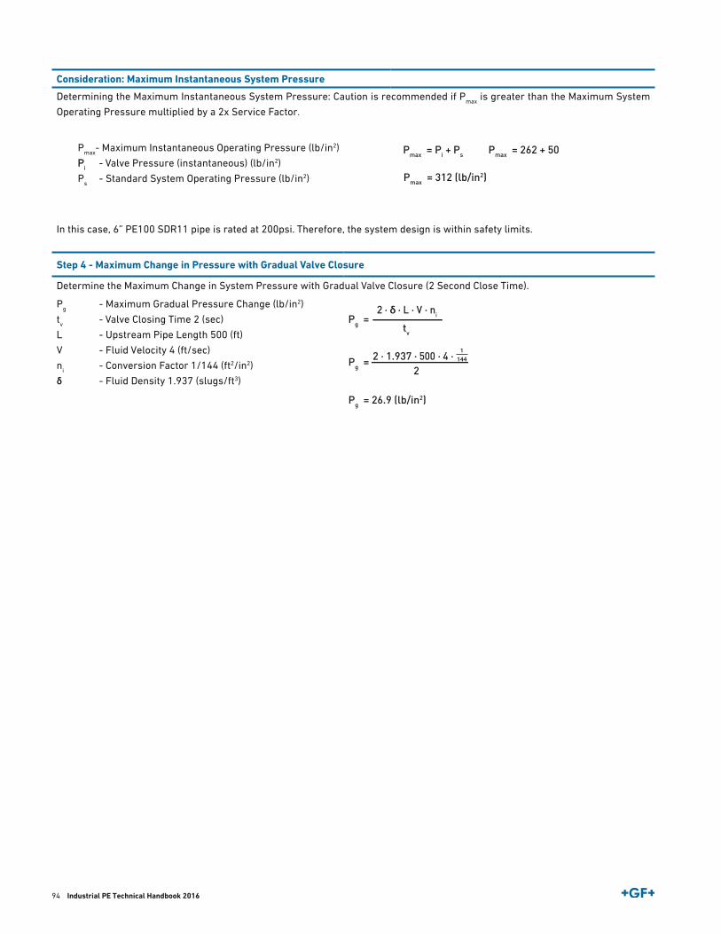
94 Industrial PE Technical Handbook 2016
Consideration: Maximum Instantaneous System Pressure
Determining the Maximum Instantaneous System Pressure: Caution is recommended if Pmax
is greater than the Maximum System
Operating Pressure multiplied by a 2x Service Factor .
Pmax
- Maximum Instantaneous Operating Pressure (lb/in2)
Pi - Valve Pressure (instantaneous) (lb/in2)
Ps - Standard System Operating Pressure (lb/in2)
Vw =K
ni · δ √ 3.19 x 105
· 1.937 √ 1144
Vw = Vw = 4870 (ft/sec)
STEP 1:
STEP 2:
STEP 3:
tc =2LVw
Pg =2 · δ · L · V · ni
tv
tc =2 · 5004870
tc = 0.2 (sec)
Pi = δ · V · Vw ni Pi =1.937 · 4 · 4870
144Pi = 262 (lb/in2)
STEP 4:
STEP 5:
Pmax = Pi + Ps Pmax = 262 + 50 Pmax = 312 (lb/in2)
Pg =2 · 1.937 · 500 · 4 ·
2Pg = 26.9 (lb/in2)
1144
Pmax = Pg + Ps Pmax = 26.9 + 50 = 76.9 (lb/in2)
Vw =K
ni · δ √ 3.19 x 105
· 1.937 √ 1144
Vw = Vw = 4870 (ft/sec)
STEP 1:
STEP 2:
STEP 3:
tc =2LVw
Pg =2 · δ · L · V · ni
tv
tc =2 · 5004870
tc = 0.2 (sec)
Pi = δ · V · Vw ni Pi =1.937 · 4 · 4870
144Pi = 262 (lb/in2)
STEP 4:
STEP 5:
Pmax = Pi + Ps Pmax = 262 + 50 Pmax = 312 (lb/in2)
Pg =2 · 1.937 · 500 · 4 ·
2Pg = 26.9 (lb/in2)
1144
Pmax = Pg + Ps Pmax = 26.9 + 50 = 76.9 (lb/in2)
In this case, 6” PE100 SDR11 pipe is rated at 200psi . Therefore, the system design is within safety limits .
Step 4 - Maximum Change in Pressure with Gradual Valve Closure
Determine the Maximum Change in System Pressure with Gradual Valve Closure (2 Second Close Time) .
Pg - Maximum Gradual Pressure Change (lb/in2)
tv - Valve Closing Time 2 (sec)
L - Upstream Pipe Length 500 (ft)
V - Fluid Velocity 4 (ft/sec)
ni - Conversion Factor 1/144 (ft2/in2)
δ - Fluid Density 1 .937 (slugs/ft3)
Vw =K
ni · δ √ 3.19 x 105
· 1.937 √ 1144
Vw = Vw = 4870 (ft/sec)
STEP 1:
STEP 2:
STEP 3:
tc =2LVw
Pg =2 · δ · L · V · ni
tv
tc =2 · 5004870
tc = 0.2 (sec)
Pi = δ · V · Vw ni Pi =1.937 · 4 · 4870
144Pi = 262 (lb/in2)
STEP 4:
STEP 5:
Pmax = Pi + Ps Pmax = 262 + 50 Pmax = 312 (lb/in2)
Pg =2 · 1.937 · 500 · 4 ·
2Pg = 26.9 (lb/in2)
1144
Pmax = Pg + Ps Pmax = 26.9 + 50 = 76.9 (lb/in2)
Vw =K
ni · δ √ 3.19 x 105
· 1.937 √ 1144
Vw = Vw = 4870 (ft/sec)
STEP 1:
STEP 2:
STEP 3:
tc =2LVw
Pg =2 · δ · L · V · ni
tv
tc =2 · 5004870
tc = 0.2 (sec)
Pi = δ · V · Vw ni Pi =1.937 · 4 · 4870
144Pi = 262 (lb/in2)
STEP 4:
STEP 5:
Pmax = Pi + Ps Pmax = 262 + 50 Pmax = 312 (lb/in2)
Pg =2 · 1.937 · 500 · 4 ·
2Pg = 26.9 (lb/in2)
1144
Pmax = Pg + Ps Pmax = 26.9 + 50 = 76.9 (lb/in2)
Vw =K
ni · δ √ 3.19 x 105
· 1.937 √ 1144
Vw = Vw = 4870 (ft/sec)
STEP 1:
STEP 2:
STEP 3:
tc =2LVw
Pg =2 · δ · L · V · ni
tv
tc =2 · 5004870
tc = 0.2 (sec)
Pi = δ · V · Vw ni Pi =1.937 · 4 · 4870
144Pi = 262 (lb/in2)
STEP 4:
STEP 5:
Pmax = Pi + Ps Pmax = 262 + 50 Pmax = 312 (lb/in2)
Pg =2 · 1.937 · 500 · 4 ·
2Pg = 26.9 (lb/in2)
1144
Pmax = Pg + Ps Pmax = 26.9 + 50 = 76.9 (lb/in2)
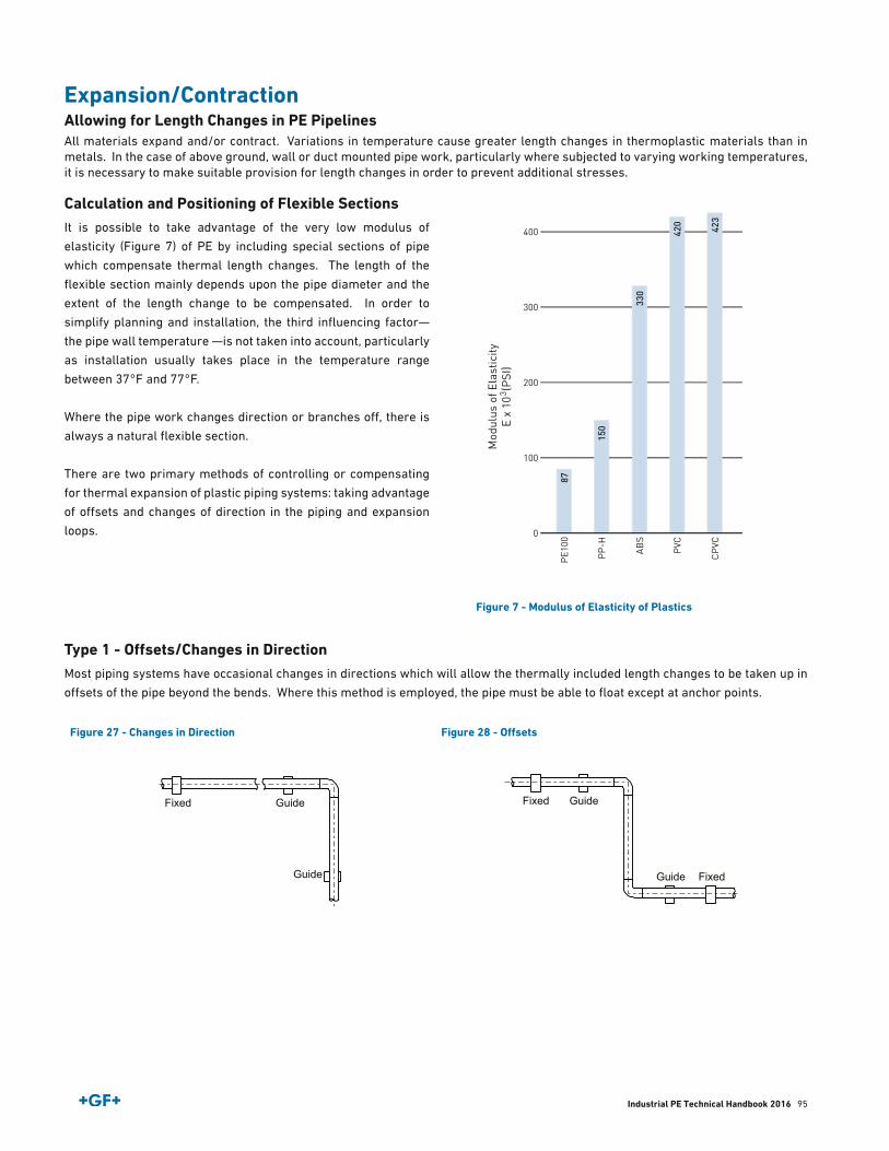
95Industrial PE Technical Handbook 2016
Expansion/ContractionAllowing for Length Changes in PE PipelinesAll materials expand and/or contract . Variations in temperature cause greater length changes in thermoplastic materials than in metals . In the case of above ground, wall or duct mounted pipe work, particularly where subjected to varying working temperatures, it is necessary to make suitable provision for length changes in order to prevent additional stresses .
Calculation and Positioning of Flexible SectionsIt is possible to take advantage of the very low modulus of
elasticity (Figure 7) of PE by including special sections of pipe
which compensate thermal length changes . The length of the
flexible section mainly depends upon the pipe diameter and the
extent of the length change to be compensated . In order to
simplify planning and installation, the third influencing factor—
the pipe wall temperature —is not taken into account, particularly
as installation usually takes place in the temperature range
between 37°F and 77°F .
Where the pipe work changes direction or branches off, there is
always a natural flexible section .
There are two primary methods of controlling or compensating
for thermal expansion of plastic piping systems: taking advantage
of offsets and changes of direction in the piping and expansion
loops . 0
100
200
300
400
87
330
150
420
423
PE1
00
AB
S
PP
-H
PVC
CP
VC
Mod
ulus
of E
last
icity
E x
10 (
PSI
)3
Figure 7 - Modulus of Elasticity of Plastics
Type 1 - Offsets/Changes in DirectionMost piping systems have occasional changes in directions which will allow the thermally included length changes to be taken up in
offsets of the pipe beyond the bends . Where this method is employed, the pipe must be able to float except at anchor points .
Figure 27 - Changes in Direction
a
6”min. 6”min.
L
Fixed Guide
FixedGuide
Fixed Guide
Guide
Fixed
Guide Guide
Fixed Guide
FixedGuide
Fixed Guide
Guide
Fixed
Guide Guide
1/5a
2/5a
1/4a
1/2a
1/4a
Figure 28 - Offsets
a
6”min. 6”min.
L
Fixed Guide
FixedGuide
Fixed Guide
Guide
Fixed
Guide Guide
Fixed Guide
FixedGuide
Fixed Guide
Guide
Fixed
Guide Guide
1/5a
2/5a
1/4a
1/2a
1/4a
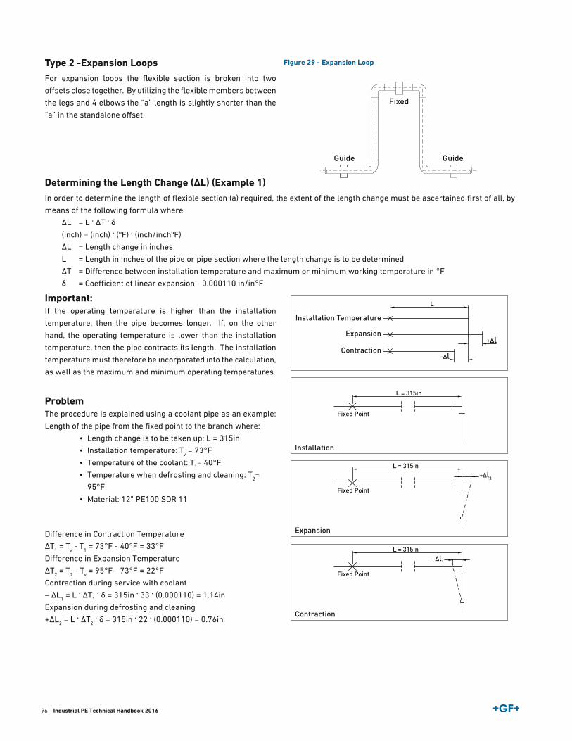
96 Industrial PE Technical Handbook 2016
Type 2 -Expansion LoopsFor expansion loops the flexible section is broken into two
offsets close together . By utilizing the flexible members between
the legs and 4 elbows the “a” length is slightly shorter than the
“a” in the standalone offset .
Figure 29 - Expansion Loop
a
6”min. 6”min.
L
Fixed Guide
FixedGuide
Fixed Guide
Guide
Fixed
Guide Guide
Fixed Guide
FixedGuide
Fixed Guide
Guide
Fixed
Guide Guide
1/5a
2/5a
1/4a
1/2a
1/4a
Determining the Length Change (ΔL) (Example 1)In order to determine the length of flexible section (a) required, the extent of the length change must be ascertained first of all, by
means of the following formula where
∆L = L · ∆T · δ
(inch) = (inch) · (ºF) · (inch/inchºF)
ΔL = Length change in inches
L = Length in inches of the pipe or pipe section where the length change is to be determined
ΔT = Difference between installation temperature and maximum or minimum working temperature in °F
δ = Coefficient of linear expansion - 0 .000110 in/in°F
Important: If the operating temperature is higher than the installation
temperature, then the pipe becomes longer . If, on the other
hand, the operating temperature is lower than the installation
temperature, then the pipe contracts its length . The installation
temperature must therefore be incorporated into the calculation,
as well as the maximum and minimum operating temperatures .
ProblemThe procedure is explained using a coolant pipe as an example:
Length of the pipe from the fixed point to the branch where:
• Length change is to be taken up: L = 315in
• Installation temperature: Tv = 73°F
• Temperature of the coolant: T1= 40°F
• Temperature when defrosting and cleaning: T2=
95°F
• Material: 12” PE100 SDR 11
Difference in Contraction Temperature
ΔT1 = T
v - T
1 = 73°F - 40°F = 33°F
Difference in Expansion Temperature
ΔT2 = T
2 - T
v = 95°F - 73°F = 22°F
Contraction during service with coolant
– ΔL1 = L · ΔT
1 · δ = 315in · 33 · (0 .000110) = 1 .14in
Expansion during defrosting and cleaning
+ΔL2 = L · ΔT
2 · δ = 315in · 22 · (0 .000110) = 0 .76in
Installation Temperature
+Δl
-Δl
L
Expansion
Contraction
L = 315in
Fixed Point
L = 315in
Fixed Point
+Δl2
L = 315in
Fixed Point
-Δl1
Expansion
Contraction
Installation
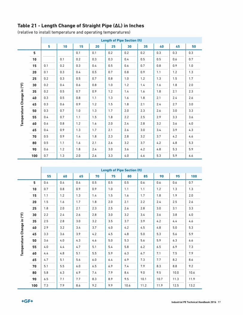
97Industrial PE Technical Handbook 2016
Table 21 - Length Change of Straight Pipe (ΔL) in Inches(relative to install temperature and operating temperatures)
Length of Pipe Section (ft)
5 10 15 20 25 30 35 40 45 50
Tem
pera
ture
Cha
nge
in (°
F)
5 0 .1 0 .1 0 .2 0 .2 0 .2 0 .3 0 .3 0 .3
10 0 .1 0 .2 0 .3 0 .3 0 .4 0 .5 0 .5 0 .6 0 .7
15 0 .1 0 .2 0 .3 0 .4 0 .5 0 .6 0 .7 0 .8 0 .9 1 .0
20 0 .1 0 .3 0 .4 0 .5 0 .7 0 .8 0 .9 1 .1 1 .2 1 .3
25 0 .2 0 .3 0 .5 0 .7 0 .8 1 .0 1 .2 1 .3 1 .5 1 .7
30 0 .2 0 .4 0 .6 0 .8 1 .0 1 .2 1 .4 1 .6 1 .8 2 .0
35 0 .2 0 .5 0 .7 0 .9 1 .2 1 .4 1 .6 1 .8 2 .1 2 .3
40 0 .3 0 .5 0 .8 1 .1 1 .3 1 .6 1 .8 2 .1 2 .4 2 .6
45 0 .3 0 .6 0 .9 1 .2 1 .5 1 .8 2 .1 2 .4 2 .7 3 .0
50 0 .3 0 .7 1 .0 1 .3 1 .7 2 .0 2 .3 2 .6 3 .0 3 .3
55 0 .4 0 .7 1 .1 1 .5 1 .8 2 .2 2 .5 2 .9 3 .3 3 .6
60 0 .4 0 .8 1 .2 1 .6 2 .0 2 .4 2 .8 3 .2 3 .6 4 .0
65 0 .4 0 .9 1 .3 1 .7 2 .1 2 .6 3 .0 3 .4 3 .9 4 .3
70 0 .5 0 .9 1 .4 1 .8 2 .3 2 .8 3 .2 3 .7 4 .2 4 .6
80 0 .5 1 .1 1 .6 2 .1 2 .6 3 .2 3 .7 4 .2 4 .8 5 .3
90 0 .6 1 .2 1 .8 2 .4 3 .0 3 .6 4 .2 4 .8 5 .3 5 .9
100 0 .7 1 .3 2 .0 2 .6 3 .3 4 .0 4 .6 5 .3 5 .9 6 .6
Length of Pipe Section (ft)
55 60 65 70 75 80 85 90 95 100
Tem
pera
ture
Cha
nge
in (°
F)
5 0 .4 0 .4 0 .4 0 .5 0 .5 0 .5 0 .6 0 .6 0 .6 0 .7
10 0 .7 0 .8 0 .9 0 .9 1 .0 1 .1 1 .1 1 .2 1 .3 1 .3
15 1 .1 1 .2 1 .3 1 .4 1 .5 1 .6 1 .7 1 .8 1 .9 2 .0
20 1 .5 1 .6 1 .7 1 .8 2 .0 2 .1 2 .2 2 .4 2 .5 2 .6
25 1 .8 2 .0 2 .1 2 .3 2 .5 2 .6 2 .8 3 .0 3 .1 3 .3
30 2 .2 2 .4 2 .6 2 .8 3 .0 3 .2 3 .4 3 .6 3 .8 4 .0
35 2 .5 2 .8 3 .0 3 .2 3 .5 3 .7 3 .9 4 .2 4 .4 4 .6
40 2 .9 3 .2 3 .4 3 .7 4 .0 4 .2 4 .5 4 .8 5 .0 5 .3
45 3 .3 3 .6 3 .9 4 .2 4 .5 4 .8 5 .0 5 .3 5 .6 5 .9
50 3 .6 4 .0 4 .3 4 .6 5 .0 5 .3 5 .6 5 .9 6 .3 6 .6
55 4 .0 4 .4 4 .7 5 .1 5 .4 5 .8 6 .2 6 .5 6 .9 7 .3
60 4 .4 4 .8 5 .1 5 .5 5 .9 6 .3 6 .7 7 .1 7 .5 7 .9
65 4 .7 5 .1 5 .6 6 .0 6 .4 6 .9 7 .3 7 .7 8 .2 8 .6
70 5 .1 5 .5 6 .0 6 .5 6 .9 7 .4 7 .9 8 .3 8 .8 9 .2
80 5 .8 6 .3 6 .9 7 .4 7 .9 8 .4 9 .0 9 .5 10 .0 10 .6
90 6 .5 7 .1 7 .7 8 .3 8 .9 9 .5 10 .1 10 .7 11 .3 11 .9
100 7 .3 7 .9 8 .6 9 .2 9 .9 10 .6 11 .2 11 .9 12 .5 13 .2
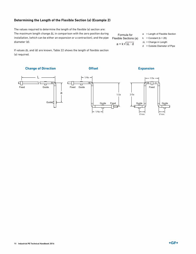
98 Industrial PE Technical Handbook 2016
Determining the Length of the Flexible Section (a) (Example 2)
The values required to determine the length of the flexible (a) section are:
The maximum length change ΔL in comparison with the zero position during
installation, (which can be either an expansion or a contraction), and the pipe
diameter (d) .
If values ΔL and (d) are known, Table 22 shows the length of flexible section
(a) required .
1.0
0.1
2.0
3.0
5.0
7.0
8.0
9.0
10.0
6.0
4.0
0.5
146.0135.0120.090.0 105.075.045.0 60.030.015.0
a = k ∆L · d
a
∆L ∆L
FlexibleSection
Formula forFlexible Sections (a)
a = Length of Flexible Section
k = Constant (k = 26)
∆L = Change in Length
d = Outside Diameter of Pipe
Leng
th C
hang
e (∆
L) in
inch
es
Flexible Section Length (a) in inches
2”
3”
4”
6”
8”
10”
12”
14”
16”
20”
24”
28”
32”
18”
22 ”
26”
30”
36”
Nom
inal
Pip
e S
ize
(d =
Act
ual O
D)
0.6
0.9
0.7
0.8
1.6
1.1
1.2
1.5
1.3
1.4
1.9
1.7
1.8
Change of Direction
a
6”min. 6”min.
L
Fixed Guide
FixedGuide
Fixed Guide
Guide
Fixed
Guide Guide
Fixed Guide
FixedGuide
Fixed Guide
Guide
Fixed
Guide Guide
1/5a
2/5a
1/4a
1/2a
1/4a
Offset
a
6”min. 6”min.
L
Fixed Guide
FixedGuide
Fixed Guide
Guide
Fixed
Guide Guide
Fixed Guide
FixedGuide
Fixed Guide
Guide
Fixed
Guide Guide
1/5a
2/5a
1/4a
1/2a
1/4a
Expansion
a
6”min. 6”min.
L
Fixed Guide
FixedGuide
Fixed Guide
Guide
Fixed
Guide Guide
Fixed Guide
FixedGuide
Fixed Guide
Guide
Fixed
Guide Guide
1/5a
2/5a
1/4a
1/2a
1/4a
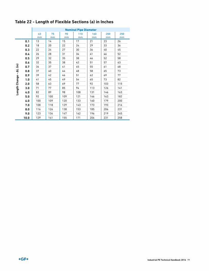
99Industrial PE Technical Handbook 2016
Table 22 - Length of Flexible Sections (a) in Inches
Nominal Pipe Diameter63
mm75
mm90
mm110 mm
160 mm
200 mm
250 mm
Leng
th C
hang
e -
ΔL
(in)
0.1 13 14 15 17 21 23 26
0.2 18 20 22 24 29 33 36
0.3 22 24 27 30 36 40 45
0.4 26 28 31 34 41 46 52
0.5 29 32 35 38 46 52 58
0.6 32 35 38 42 51 57 63
0.7 34 37 41 45 55 61 68
0.8 37 40 44 48 58 65 73
0.9 39 42 46 51 62 69 77
1.0 41 45 49 54 65 73 82
2.0 58 63 69 77 92 103 115
3.0 71 77 85 94 113 126 141
4.0 82 89 98 108 131 146 163
5.0 92 100 109 121 146 163 182
6.0 100 109 120 133 160 179 200
7.0 108 118 129 143 173 193 216
8.0 116 126 138 153 185 206 231
9.0 123 134 147 162 196 219 245
10.0 129 141 155 171 206 231 258
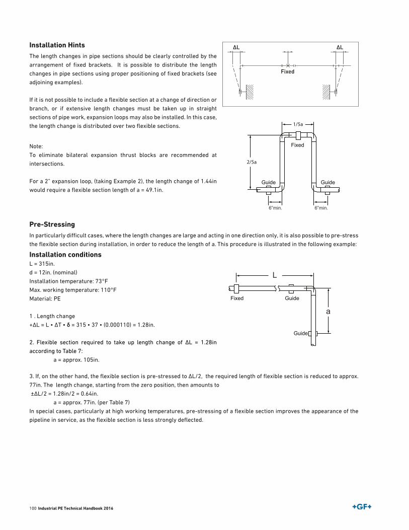
100 Industrial PE Technical Handbook 2016
Installation HintsThe length changes in pipe sections should be clearly controlled by the
arrangement of fixed brackets . It is possible to distribute the length
changes in pipe sections using proper positioning of fixed brackets (see
adjoining examples) .
If it is not possible to include a flexible section at a change of direction or
branch, or if extensive length changes must be taken up in straight
sections of pipe work, expansion loops may also be installed . In this case,
the length change is distributed over two flexible sections .
Note:
To eliminate bilateral expansion thrust blocks are recommended at
intersections .
For a 2” expansion loop, (taking Example 2), the length change of 1 .44in
would require a flexible section length of a = 49 .1in .
ΔL ΔL
LL/2 L/2
L = 394in - ΔL/2
a = 3.84in
a = 1.92in
L = 394in
Not Recommended Recommended
Fixed
F F
ΔL ΔL/2 ΔL/2
ΔL/2 ΔL/2
F
F F
ΔL
ΔL/2
F
F
a
6”min. 6”min.
L
Fixed Guide
FixedGuide
Fixed Guide
Guide
Fixed
Guide Guide
Fixed Guide
FixedGuide
Fixed Guide
Guide
Fixed
Guide Guide
1/5a
2/5a
1/4a
1/2a
1/4a
Pre-StressingIn particularly difficult cases, where the length changes are large and acting in one direction only, it is also possible to pre-stress
the flexible section during installation, in order to reduce the length of a . This procedure is illustrated in the following example:
Installation conditionsL = 315in .
d = 12in . (nominal)
Installation temperature: 73°F
Max . working temperature: 110°F
Material: PE
1 . Length change
+ΔL = L • ΔT • δ = 315 • 37 • (0 .000110) = 1 .28in .
2 . Flexible section required to take up length change of ΔL = 1 .28in
according to Table 7:
a = approx . 105in .
a
6”min. 6”min.
L
Fixed Guide
FixedGuide
Fixed Guide
Guide
Fixed
Guide Guide
Fixed Guide
FixedGuide
Fixed Guide
Guide
Fixed
Guide Guide
1/5a
2/5a
1/4a
1/2a
1/4a
3 . If, on the other hand, the flexible section is pre-stressed to ΔL/2, the required length of flexible section is reduced to approx .
77in . The length change, starting from the zero position, then amounts to
±ΔL/2 = 1 .28in/2 = 0 .64in .
a = approx . 77in . (per Table 7)
In special cases, particularly at high working temperatures, pre-stressing of a flexible section improves the appearance of the
pipeline in service, as the flexible section is less strongly deflected .

101Industrial PE Technical Handbook 2016
InstallationThe Incorporation of ValvesValves should be mounted as directly as possible; they should be formed as fixed points . The actuating force is thus transmitted
directly, and not through the pipeline . The length changes, starting from the valve, are to be controlled as described previously .
Note:
• All Plastic Valves that include additional accessories, actuators or items that will increase load or stress on the piping system
must be fully supported either independently or by mounting points located on the valve body .
• All metal valves must be supported . Should metal valves not be adequately supported, there is a significant risk of stress fatigue
and possible system failure .
• For safe mounting of plastic valves, Georg Fischer valves are equipped with metal threaded inserts for direct mounted
installation .
Vibration DampenersThere are two principal ways to control stress caused by vibration . You can usually observe the stability of the system during initial
operation and add restraints or supports as required to reduce effects of equipment vibration . Where necessary restraint fittings may
be used to effectively hold pipe from lifting or moving laterally .
In special cases where the source of vibration is excessive (such as that resulting from pumps running unbalanced), an elastomeric
expansion joint or other vibration absorber may be considered . This may be the case at pumps where restricting the source of
vibration is not recommended .
Pipe Bracket Support Centers and Fixation of Plastic PipelinesGeneral Pipe Supports and BracketsPE pipelines need to be supported at specific intervals, depending upon the material, the average pipe wall temperature, the specific
gravity of the medium, and the diameter and wall thickness of the pipe . The determination of the pipe support centers has been based
on the permissible amount of deflection of the pipe between two brackets . The pipe bracket centers given in Table 8 are calculated
on the basis of a permissible deflection of max . 0 .01 inch (0 .25 cm) between two brackets .
Pipe Bracket Spacing in the Case of Fluids with Specific Gravity ≤ 1 .0 (62 .4 Lb/Ft3)
Where fluids with a specific gravity exceeding 1g/cm3 are to be conveyed, the pipe bracket centers given in Table 8 must be divided by
the specific gravity of the solution .
Example: 20” pipe carrying media with a specific gravity of 1 .6 = 13ft divided by 1 .6 = approx . 8 .1ft centers .
Installation of Closely Spaced Pipe Brackets
A continuous support may be more advantageous and economical than pipe brackets for small diameter horizontal pipe work,
especially in a higher temperature range . Installation in a “V” or “U” shaped support made of metal or heat-resistant plastic material
has proven satisfactory .
Pipe Bracket Requirements
When mounted, the inside diameter of the bracket must be greater than the outside diameter of the pipe, in order to allow length
changes of the pipe at the specified points . The inside edges of the pipe bracket must be formed in such a way that no damage to the
pipe surface is possible . George Fischer pipe brackets meet these requirements . They are made of plastic and may be used under
rugged working conditions and also in areas where the pipe work is subjected to the external influence of aggressive atmospheres or
media . Georg Fischer pipe brackets are suitable for PE, PVC, CPVC, PP and PVDF pipes .
Arrangement of Fixed Brackets
If the pipe bracket is positioned directly beside a fitting, the length change of the pipeline is limited to one direction only (one-sided
fixed point) .
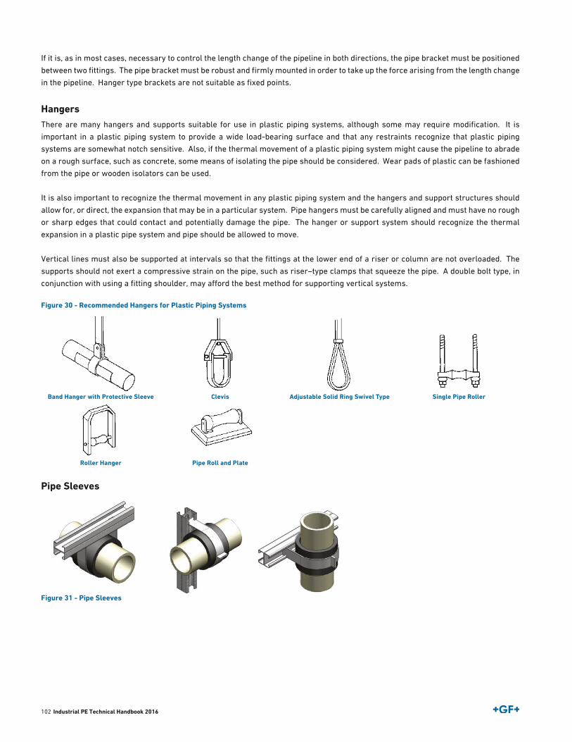
102 Industrial PE Technical Handbook 2016
If it is, as in most cases, necessary to control the length change of the pipeline in both directions, the pipe bracket must be positioned
between two fittings . The pipe bracket must be robust and firmly mounted in order to take up the force arising from the length change
in the pipeline . Hanger type brackets are not suitable as fixed points .
HangersThere are many hangers and supports suitable for use in plastic piping systems, although some may require modification . It is
important in a plastic piping system to provide a wide load-bearing surface and that any restraints recognize that plastic piping
systems are somewhat notch sensitive . Also, if the thermal movement of a plastic piping system might cause the pipeline to abrade
on a rough surface, such as concrete, some means of isolating the pipe should be considered . Wear pads of plastic can be fashioned
from the pipe or wooden isolators can be used .
It is also important to recognize the thermal movement in any plastic piping system and the hangers and support structures should
allow for, or direct, the expansion that may be in a particular system . Pipe hangers must be carefully aligned and must have no rough
or sharp edges that could contact and potentially damage the pipe . The hanger or support system should recognize the thermal
expansion in a plastic pipe system and pipe should be allowed to move .
Vertical lines must also be supported at intervals so that the fittings at the lower end of a riser or column are not overloaded . The
supports should not exert a compressive strain on the pipe, such as riser–type clamps that squeeze the pipe . A double bolt type, in
conjunction with using a fitting shoulder, may afford the best method for supporting vertical systems .
Figure 30 - Recommended Hangers for Plastic Piping Systems
Band Hanger with Protective Sleeve Clevis Adjustable Solid Ring Swivel Type Single Pipe Roller
Roller Hanger Pipe Roll and Plate
Pipe Sleeves
Figure 31 - Pipe Sleeves
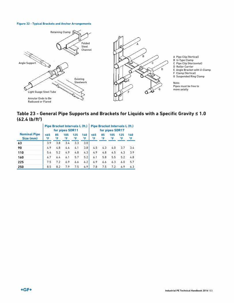
103Industrial PE Technical Handbook 2016
Figure 32 - Typical Brackets and Anchor Arrangements
A Pipe Clip (Vertical)B U-Type ClampC Pipe Clip (Horizontal)D Roller CarrierE Angle Bracket with U-ClampF Clamp (Vertical)G Suspended Ring Clamp
Note:Pipes must be free tomove axially
Retaining Clamp
FoldedSteelChannel
Angle Support
Light Guage Steel Tube
Annular Ends to BeRadiused or Flared
ExistingSteelwork
A
B
C
D
E
FG
Table 23 - General Pipe Supports and Brackets for Liquids with a Specific Gravity ≤ 1.0 (62.4 lb/ft3)
Nominal Pipe Size (mm)
Pipe Bracket Intervals L (ft.) for pipes SDR11
Pipe Bracket Intervals L (ft.) for pipes SDR17
≤65 °F
85 °F
105 °F
125 °F
140 °F
≤65 °F
85 °F
105 °F
125 °F
140 °F
63 3 .9 3 .8 3 .4 3 .3 3 .0
90 4 .9 4 .8 4 .4 4 .1 3 .8 4 .5 4 .3 4 .0 3 .7 3 .4
110 5 .4 5 .2 4 .9 4 .8 4 .3 4 .9 4 .8 4 .5 4 .3 3 .9
160 6 .7 6 .4 6 .1 5 .7 5 .2 6 .1 5 .8 5 .5 5 .2 4 .8
225 7 .5 7 .2 6 .9 6 .6 6 .2 6 .9 6 .6 6 .3 6 .0 5 .7
250 8 .5 8 .2 7 .9 7 .5 6 .9 7 .8 7 .5 7 .2 6 .9 6 .3

104 Industrial PE Technical Handbook 2016
RestraintRestraint is rigidly anchoring the pipe runs to the building structure at appropriate places so that thermally-induced dimension
changes will be replaced by thermally-induced stresses . This can be accomplished by use of adequately strong clamps or supports
along with a properly engineered pipe clamp interface to hold the pipe in place . For horizontal runs, braced clamp type hangers may
be used . For floor penetrations, extension riser clamps may be used .
Underground installation in properly backfilled trenches may be considered to be a restrained system and not subject to thermally-
induced dimensional changes . For more details, see the FM section .
It should be noted that two unique properties of PE4710 make for the success of these methods of handling thermal expansion .
PE4710 is not subject to mechanical stress cracking . It can be stressed for long periods of time in what might be considered unfriendly
environments without harm . In addition, PE4710 has an extremely high fatigue life . Its “self-hinge” characteristics are well known and
the piping materials will stand repeated drastic flexures without harm .
Cold Weather InstallationsIn general, it is good practice when possible, to maintain an ambient temperature above 40˚F (4˚C) . However, low temperature fusions
to -10˚F (-23˚C) are easily accomplished utilizing automatic temperature compensation capable fusion machines
(MSA 330/340) from GF .
Note: Material and fusion machines must be the same temperature prior to fusion . This can be achieved when components and
machines are in the same environment for 1 hour per ½” material wall thickness .For further information, please consult you local sales representative.
Flammability and Fire Rated ConstructionThe fire protection officials and code officials are becoming sensitive to the smoke generation and flammability of plastic materials
used in building construction, and plastic piping is naturally included in these concerns . To satisfy the fire safety requirements set
out by the authorities, the engineers and architects must have a better understanding of the plastics used in piping, appropriate test
methods and means of protection against fire dangers attributed to plastic piping .
To put this into the proper perspective, the architect, engineer and administrative authority must realize that, in the vast majority of
cases, fires commonly start and continue to develop in occupied areas of a building and not within the walls and chases where plastic
piping is more commonly installed .
Laboratory Fire TestsThe following are common laboratory tests conducted on small samples of plastic material and are useful in characterizing and
comparing different plastics . However, these tests are of only limited use in predicting the behavior of the materials in real fire
situations .
ASTM D635 - Rate of Burning and/or Extent and Time of Burning of Self Supporting Plastics in a Horizon-tal PositionOne half-inch wide by five-inch long horizontal specimens are exposed to a burner flame . The time of burning and distance burned
are recorded . The results are reported as measured, except in the case where the minimum values apply (time of burning is “less
than five seconds” and the minimum extent of burning is “less than one quarter-inch”) .
UL94 - Standard for Safety of Flammability of Plastic MaterialsOne half-inch wide by five-inch long vertical specimens are exposed repeatedly to a burner flame . Time of burning, possible dripping
of burning particles and afterglow are observed . Results are reported as V-0, V-1 or V-2, depending on test results .
105Industrial PE Technical Handbook 2016
ASTM D2843 - Density of Smoke from the Burning or Decomposition of PlasticsA one-quarter inch by one inch by one inch sample is exposed to a propane burner flame and light transmission through the smoke
generated by the burning plastic is measured with a standard lamp and photocell for four minutes . Results are reported as light
absorption and smoke density .
ASTM D2863 - Minimum Oxygen Concentration to Support Candle-Like Combustion of Plastics (Oxygen Index)
A one-eighth inch by one-quarter inch by three to six inch long specimen is burned in a variable oxygen-nitrogen mixture to determine the percentage oxygen required to maintain combustion.
Large Scale Tests These tests are run on full-sized wall or floor (floor-ceiling) assemblies or on large material specimens . They are intended to
determine the response of varying construction methods and materials in actual fire conditions .
ASTM E119 - Fire Tests of Building Construction and Materials NFPA251 • UL263
• UBC43-1
Wall sections of at least 100 square feet in size are attached as the front wall of a furnace and exposed to a flaming environment . The
temperature rises according to a standard time temperature curve . The test specimen may or may not be exposed to vertical or
horizontal loads . The specimen, after exposure, may be subjected to a high pressure hose stream to determine its integrity after
exposure .
This test is universally accepted as the method of rating wall assemblies for fire resistance as related to time of exposure . Ratings
may be 1, 2, 3 or 4 hours, depending on the time for the temperature to rise to not more than 250°F (121°C) above its initial temperature
on the non-exposed face . Floor and floor-ceiling assemblies of at least 180 square feet in size are also tested per ASTM E119 as the
roofs of a floor-ceiling furnace, and rated on the basis of the time for the temperature to rise 250°F (121°C) above the initial temperature
on the unexposed face, as for walls .
ASTM E814 - Fire Tests of Through-Penetration Fire StopsThis test method (published Spring 1982) is essentially identical to the ASTM E119 test except that it is intended to determine the
ability of fire-stopping methods and devices to maintain the fire rating (integrity) of rated fire-resistive walls, floors or floor-ceiling
assemblies which are penetrated by pipe, conduits or cables .
ASTM E84 - Surface Burning Characteristics of Building Materials • NFPA255
• UL723
• UBC42-1
As stated, this test is intended for testing of surface finish materials which are capable of supporting themselves or of being supported
other than by support on the under-side of the test specimen . Samples are 20 inches (min .) wide by 24 feet long and are attached to
the roof of an 18 inch by 30 foot furnace .
Burning characteristics of the samples are stated as percentage of the rate of burning of red oak .
This test, being specifically aimed at testing surface finish materials, is recognized as not applying to plastic pipe by those who
understand the test method and application environment . The National Fire Protection Association has stated that the test is not to
be applied to plastic pipe and that the pipe should be tested as a component of a wall or floor assembly in the ASTM E119 test, where
the materials are most commonly used .
Fire Protection Methods for Wall Penetration and Return Air PlenumsFor fire resistance rated wall penetrations, penetrations through horizontal assemblies, etc . use listed and approved firestopping
with ratings determined by ASTM E814 or UL1479 for use with plastic piping .

106 Industrial PE Technical Handbook 2016

GF Piping Systems
Item #1337 (5/16)© Georg Fischer LLC
The technical data are not binding . They neither constitute expressly warranted characteristics nor guaranteed properties nor a guaranteed durability . They are subject to modification . Our General Terms of Sale apply .
GF Piping SystemsTel . (714) 731-8800, Toll Free (800) 854-4090Fax (800) 426-7188 us .ps@georgfischer .com www .gfpiping .com
Argentina / Southern South AmericaGeorg Fischer Central Plastics Sudamérica S .R .L .Buenos Aires, ArgentinaPhone +54 11 4512 02 90gfcentral .ps .ar@georgfischer .comwww .gfps .com/ar
AustraliaGeorge Fischer Pty LtdRiverwood NSW 2210 AustraliaPhone +61 (0) 2 9502 8000 australia .ps@georgfischer .comwww .gfps .com/au
AustriaGeorg Fischer Rohrleitungssysteme GmbH3130 HerzogenburgPhone +43 (0) 2782 856 43-0austria .ps@georgfischer .comwww .gfps .com/at
Belgium / LuxembourgGeorg Fischer NV/SA1070 Bruxelles/BrüsselPhone +32 (0) 2 556 40 20be .ps@georgfischer .comwww .gfps .com/be
BrazilGeorg Fischer Sist . de Tub . Ltda .04795-100 São PauloPhone +55 (0) 11 5525 1311br .ps@georgfischer .comwww .gfps .com/br
CanadaGeorg Fischer Piping Systems LtdMississauga, ON L5T 2B2Phone +1 (905) 670 8005Fax +1 (905) 670 8513ca .ps@georgfischer .comwww .gfps .com/ca
ChinaGeorg Fischer Piping Systems Ltd Shanghai 201319Phone +86 21 3899 3899 china .ps@georgfischer .comwww .gfps .com/cn
Denmark / IcelandGeorg Fischer A/S2630 TaastrupPhone +45 (0) 70 22 19 75info .dk .ps@georgfischer .comwww .gfps .com/dk
FinlandGeorg Fischer AB01510 VANTAAPhone +358 (0) 9 586 58 25 Fax +358 (0) 9 586 58 29info .fi .ps@georgfischer .comwww .gfps .com/fi
FranceGeorg Fischer SAS95932 Roissy Charles de Gaulle CedexPhone +33 (0) 1 41 84 68 84fr .ps@georgfischer .comwww .gfps .com/fr
GermanyGeorg Fischer GmbH73095 Albershausen Phone +49 (0) 7161 302-0info .de .ps@georgfischer .comwww .gfps .com/de
IndiaGeorg Fischer Piping Systems Ltd400 076 MumbaiPhone +91 224007 2001branchoffice@georgfischer .comwww .gfps .com/in
ItalyGeorg Fischer S .p .A .20063 Cernusco S/N (MI)Phone +39 02 921 861it .ps@georgfischer .comwww .gfps .com/it
JapanGeorg Fischer Ltd556-0011 Osaka, Phone +81 (0) 6 6635 2691jp .ps@georgfischer .comwww .gfps .com/jp
KoreaGeorg Fischer Piping Systems271-3 Seohyeon-dong Bundang-guSeongnam-si, Gyeonggi-doSeoul 463-824Phone +82 31 8017 1450Fax +82 31 8017 1454kor .ps@georgfischer .comwww .gfps .com/kr
MalaysiaGeorge Fischer (M) Sdn . Bhd .40460 Shah Alam, Selangor Darul EhsanPhone +60 (0) 3 5122 5585my .ps@georgfischer .comwww .gfps .com/my
Mexico / Northern Latin AmericaGeorg Fischer S .A . de C .V .Apodaca, Nuevo LeonCP66636 MexicoPhone +52 (81) 1340 8586Fax +52 (81) 1522 8906mx .ps@georgfischer .comwww .gfps .com/mx
Middle EastGeorg Fischer Piping Systems (Switzerland) LtdDubai, United Arab EmiratesPhone +971 4 289 49 60gcc .ps@georgfischer .comwww .gfps .com/int
NetherlandsGeorg Fischer N .V .8161 PA EpePhone +31 (0) 578 678 222 nl .ps@georgfischer .comwww .gfps .com/nl
New ZealandGeorg Fischer Ltd13 Jupiter Grove, Upper Hutt 5018PO Box 40399, Upper Hutt 5140Phone +64 (0) 4 527 9813nz .ps@georgfischer .comwww .gfps .com/nz
NorwayGeorg Fischer AS1351 Rud Phone +47 67 18 29 00no .ps@georgfischer .comwww .gfps .com/no
PolandGeorg Fischer Sp . z o .o .05-090 Sekocin Nowy Phone +48 (0) 22 31 31 0 50 poland .ps@georgfischer .comwww .gfps .com/pl
RomaniaGeorg Fischer Piping Systems (Switzerland) Ltd020257 Bucharest - Sector 2Phone +40 (0) 21 230 53 80ro .ps@georgfischer .comwww .gfps .com/int
RussiaGeorg Fischer Piping Systems (Switzerland) LtdMoscow 125047Phone +7 495 258 60 80ru .ps@georgfischer .comwww .gfps .com/ru
SingaporeGeorge Fischer Pte Ltd11 Tampines Street 92, #04-01/07528 872 SingaporePhone +65 6747 0611sgp .ps@georgfischer .comwww .gfps .com/sg
Spain / PortugalGeorg Fischer S .A .28046 MadridPhone +34 (0) 91 781 98 90es .ps@georgfischer .comwww .gfps .com/es
SwedenGeorg Fischer AB117 43 StockholmPhone +46 (0) 8 506 775 00info .se .ps@georgfischer .comwww .gfps .com/se
SwitzerlandGeorg Fischer Rohrleitungssysteme (Schweiz) AG8201 SchaffhausenPhone +41 (0) 52 631 30 26ch .ps@georgfischer .comwww .gfps .com/ch
TaiwanGeorg Fischer Co ., LtdSan Chung Dist ., New Taipei CityPhone +886 2 8512 2822Fax +886 2 8512 2823www .gfps .com/tw
United Kingdom / IrelandGeorge Fischer Sales LimitedCoventry, CV2 2STPhone +44 (0) 2476 535 535uk .ps@georgfischer .comwww .gfps .com/uk
USA / CaribbeanGeorg Fischer LLCIrvine, CA 92618Phone +1 (714) 731-8800 Toll Free +1 (800) 854-4090us .ps@georgfischer .comwww .gfpiping .com
VietnamGeorge Fischer Pte Ltd136E Tran Vu, Ba Dinh District, HanoiPhone +84 4 3715 3290 Fax +84 4 3715 3285
International Georg Fischer Piping Systems (Switzerland) Ltd8201 Schaffhausen/SwitzerlandPhone +41 (0) 52 631 30 03Fax +41 (0) 52 631 28 93info .export@georgfischer .comwww .gfps .com/int


