INDUSTRIAL SAFETY AND RISK MANAGEMENT Compiled by B Nedumaran Assistant Professor Department of Chemical Engineering Sri Venkateswara College of Engineering Sriperumbudur India October 8, 2004
Transcript
INDUSTRIAL SAFETY
AND RISK MANAGEMENT
Compiled byB Nedumaran
Assistant ProfessorDepartment of Chemical Engineering
Sri Venkateswara College of EngineeringSriperumbudur
Survival and prosperity decide the success of any business activity. Risk isinherent in all the tasks we undertake. So also, with the business activity, noone likes to meet adverse effects while taking some risks, particularly the non-speculative or pure risks. Such risks, which involve only loss, include:
• Physical harm to employees
• Property damage to the organization
• Physical harm or property damage to public
• Capital income loss
• Security loss etc
In order to reduce the risk, the potential hazards that are likely to result inloss are to be eliminated or controlled to the possible extent. To decide on theloss control approaches, the hazards are to be identified.
1.2 What is Hazard?
Hazard as relates to ’Accident’ is defined as the potential for causing harm topersons, damage to property or environmental degradation. It will particularly
1D98A, Sowbhagya Colony, K K Nagar, Chennai - 600078
3
4 CHAPTER 1. MODERN CONCEPT OF ACCIDENT PREVENTION
cause unwanted transfer of energy and can occur in random variations of normaloperations or from changes in physical or human factors
The ’Change’ mentioned in the ’Anatomy of Hazard’ given below, can bechanged in the process, personnel, material, methods, environment, tools andequipment, or control system etc. In many industrial units, safety managementsystem revolves around minimizing the occupational injuries. In a few unitsthe system extends to controlling the near misses. These are reactive approach.The best safety management system will be adopting a proactive approach thatis hazards are controlled by minimizing the errors since it will be difficult toeliminate the ’changes’ in the industrial scenario.
1.3 What causes the hazards?
As per the definition, hazards are due to transfer of energy in one form or other.If the energy transferred os more than the withstanding capacity at the receivingend, hazard is created. Haddon, a researcher, has enumerated a few forms ofenergy in the industrial situation. They are:
Energy ExamplesKinetic Rotating, Revolving, Vibratory,
Reciprocating, Falling objectsetc
Potential Solid objects, physical strength,materials, stored pressure, coiledspring etc.
Ionizing radiation Radio active substancesNon ionizing radiation Electro magnetic wavesBiological Micro organisms
Table 1.1: Forms of Energy Transfer
The human system or any other object or species has tolerance levels orthresholds for each form of energy. The quantity of such energy, particularlynear the threshold limit must be determined in order to decide on the controlmethod to eliminate or reduce the impact of hazard.
Mc Farland, another researcher in this field, has said ” all accidental injuriesand damages result (1) from application of specific forms of energy in amounts
1.4. NEED FOR HAZARD IDENTIFICATION: 5
exceeding the resistance of the tissues or structures upon which the impinge,or (2) when there is interference in the normal exchange of energy between theorganism and the environment (eg. As in suffocation by drowning) Thus, thevarious forms of energy Constitute the direct causes of injuries in accidents.Therefore, prevention of injuries can often be achieved by controlling the sourceof energy, or the vehicles or carriers through which the energy reaches the body”.This theory paves the way to controlling the hazards.
1.4 Need for Hazard Identification:
A good professional manager is the one who adopts the most advantage methodto manage or solve a problem. Best medical or surgical management on a pa-tient is possible only through correct diagnosis, which is dependent on gooddiagnostic tools. The hazard control/ management also needs good identifi-cation techniques. It is a requirement under Factories Act, 1948 that everyoccupier shall ensure, so far as is reasonably practicable, the health, safety andwelfare of all workers while they are at work in the factory which implies thathe should take measures to establish that hazards are eliminated or reasonablycontrolled. Section 41A of the ibid act, which deals with site appraisal commit-tee, and rule made there under, requires risk analysis report for which hazardsare to be identified. A number of other enactments also require risk analysisreport. Therefore, hazard identification is essential for:
1. Statutory compliance
2. Minimize loss exposure and risk
3. Better safety management
1.5 Hazard Identification Techniques:
Many techniques are available for identifying the hazards. There are reactive(post hazard scenario) or procative (predictive) tools for hazard identification.Some of the proven tools are mentioned below. These are not exhaustive.
1.6 Reactive approach
• Accident Investigation
• Plant Inspection
• Critical Incidence Technique (CIT)
• Incident Recall Technique
1.7 Proactive approach
• Job Safety Analysi (JSA)
• Failure Mode and Effect Analysis (FTA)
6 CHAPTER 1. MODERN CONCEPT OF ACCIDENT PREVENTION
• Hazard and Operability Study (HAZOP)
• Fault Tree and Event Tree Analysis (FTA & ETA)
• Management Oversight Risk Tree (MORT) Analysis
• Fire Explosion and Toxicity Index (FETI)
• Material / Chemical Reactive Analysis
• Consequence analysis etc
Each of the above technique has its own merits and demerits. Depending onthe individual problem, the type of the technique should be applied to identifythe hazard. Some guidelines are given here to choose the right technique.
HAZOP study gives optimalresults when conducted at the design stage andwhenever a major redesign is planned. It can also be used for the existingplants. The success of the HAZOP study depends on the technical knowledgeand cooperation of the HAZOP team members and the accuracy of the P& Idiagram used in the study.
Safety audit is best suited for the running plant. It is very useful in iden-tifying the sources of loss in every area of the industrial activity. In order toget best out of safety audit, the author should be knowledgeable both in theprocess and safety.
Both, the FTA and MORT are predictive techniques and done on the desk.They are suited to workout the probability of an event by feeding the failurerate data to each of the logical occurrences in the analysis. FMEA and FETIcan give the risk score, subjectively.
JAS is one of the old and useful hazard identification techniques. It requiresindustrial engineering knowledge in addition to safety, to split the job into var-ious components and analyze the unsafe condition or unsafe act likely to occurand the remedial measures to avoid accidents.
When a system can not tolerate any error on the part of the operator, (eg.Control room) it will be prudent to place a person with least error potential.THERP analysis will certainly contribute to reduction of risk due to humanerror in highly sensitive and vulnerable areas
In order to monitor the hazards at work place on a continual basis, CIT willbe very useful since trained analysts will be available in the work area, who canidentify the hazards and communicate to the management, in advance, and thehazard can be removed.
After identifying the hazard, the probability of risk and tolerance matrix isdeveloped and a decision is taken to control the hazard or otherwise. Such amatrix is given below:
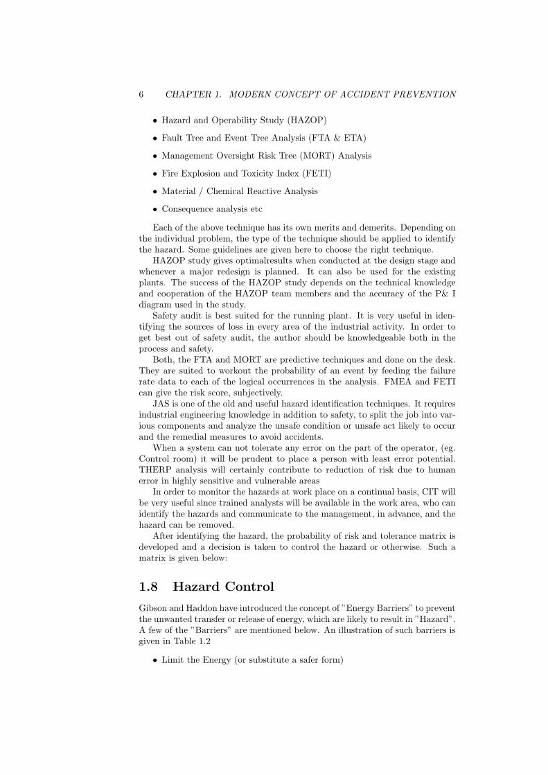
1.8 Hazard Control
Gibson and Haddon have introduced the concept of ”Energy Barriers” to preventthe unwanted transfer or release of energy, which are likely to result in ”Hazard”.A few of the ”Barriers” are mentioned below. An illustration of such barriers isgiven in Table 1.2
• Limit the Energy (or substitute a safer form)
1.9. CONCLUSION 7
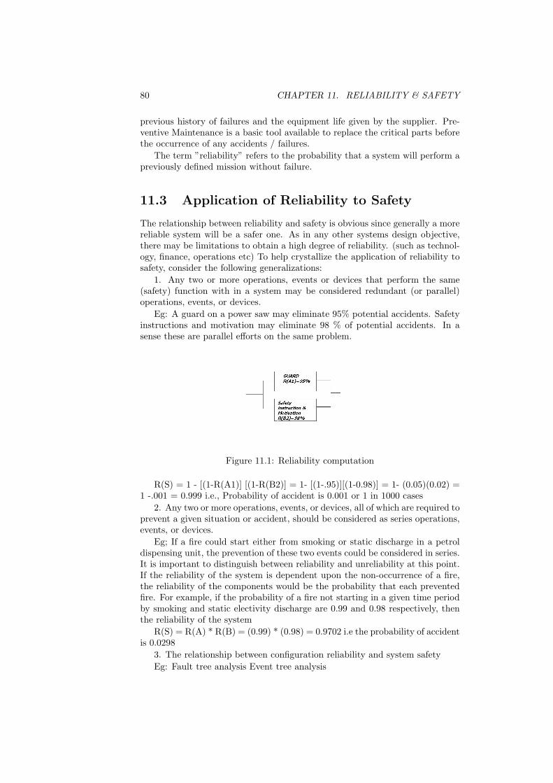
Figure 1.1: Risk Tolerance Matrix
Figure 1.2: Accident Process
• Prevent the build up of Energy
• Prevent the release
• Provide gadget for slow release
• Channel the release away - separate in time or space
• Put a barrier on the energy source
• Put a barrier between the energy source and the men or objects
• Block or attenuate the energy by putting a barrier on men or object
• Raise the injury or damage threshold
• Treat or repair
• Rehabilitate
1.9 Conclusion
There are at least 25 proven techniques for hazard identification. Only the mod-ern and practical techniques are mentioned in this paper. New techniques like”sequence of time of Event Plotting” (STEP), Bio-Rhythm etc are introducedin the developed countries as hazard identification tools. With the changingeconomic scenario, in India, the shop floor managers should equip themselvesin the risk management for which hazard identification and control are essentialelements.
8 CHAPTER 1. MODERN CONCEPT OF ACCIDENT PREVENTION
TYPE GRINDERS OTHERS1. Limit En-ergy
Speed Size Low voltage instruments, usesafet solvents, limit quantities
2. Preventbuild-up
Limit controls, fuses, use sharptools, Gas detectors, Floor load-ing
Exhaust Rope off area, Aisle marking,Electrical grounding, Lock outs,inter locks
6. On source Guard Sprinklers, Filters, Acoustictreatment
7. Between Glass shield Rail on aisle, Fire doors, WeldingShields
8. On manor object
Goggles Shoes, Hard hats, Gloves, Respi-rators, heavy protectors
9. RaiseThreshold
Selection, Calluses, Acclimatizeto heat or cold, Damage resistantmaterial
10. Amelio-rate
Emergency showers, transfer tolow radiation job, Rescue, Emer-gency medical care
Table 1.2: Illustration for Barriers
1.10 References
1. Management Oversight Risk Tree by W G Johnson et al.
2. Management Guide to Loss Control by Frank E Bird Jr
3. Professional Executive Programme by George L Germain
4. Human engineering Guide to Equipment Design by Van Cott and Kinkade
5. Various publications of National Safety Council, USA
Chapter 2
Factories Act - SafetyProvisions
D. VasudevanChief Inspector of Factories (Retd.)Chennai
2.1 Introduction
In India, the first Factories Act was passed in 1881. The present Factories Act1948 is the sixth Act. The salient features of these acts are as follows:
1. First Factories Act - 1881
• Applicability –100 or more workers
• To protect Children - Few Health and Safety Measures
2. Second Factories Act - 1891
• Applicability- 50 or more workers
• Children below 9 years - prohibited
• Children below 9 to 14 years - Working hours: 7 hrs / day
• Children and Women - Prohibited in Night Shifts
3. Third Factories Act - 1911
• Applicability -50 or more workers
• Children working hours: 6 hours / day
• Adult working hours: 12 hours / day - 1 hour rest interval
• Children and Women - Prohibited in Night Shifts
• Inspection made stringent.
4. Fourth Factories Act - 1922
9
10 CHAPTER 2. FACTORIES ACT - SAFETY PROVISIONS
• Applicability -20 or more workers with power
• 100 or more workers - Provincial Government can enforce.
• Adult working hours: 11 hours / day - 60 hours / week
• 1 hour rest interval after 6 hours
• 1 day weekly off.
• OT Hours - Double wages
5. Fifth Factories Act - 1934 [Enacted after the report of Royal Commissionon Labour - Whitely commission 1929 - 31]
• Seasonal Factories working hours: 11 hours / day & 60 hours / week
• Perennial Factories working hours: 10 hours / day & 54 hours / week
• Children: 12 to 15 years working hours: 5 hours / day
• Women working hours: 10 hours / day - Night Prohibited.
• Overtime: 1.5 times wages
• Provisions for Health, Security, Rest House, Cradles, First Aid, etc.
• 1946 Amendment
• Working hours: 9 hours / day and 48 hours / week
• Seasonal 10 hours / day and 54 hours /week
• Overtime: Double wages
• 1947 Amendment
• Canteen more than 200 workers
6. Sixth Factories Act -1948 (Present Act)
• ILO Conventions on Industrial Hygiene incorporated.
• Comprehensive Act to protect the Labour in Industries
• Detailed Health Safety and Welfare Provisions
Important Salient Features
• Distinction between seasonal and perennial factories removed.
• Act extended to all factories With power and 10 or more workers Withoutpower and 20 or more workers
• State Government powers to notify factories - 85(i)
• Detailed Provisions regarding health, safety and welfare of the workersImproved working conditions
• Detailed Provisions for working hours / holidays / leave / leave with wages/ overtime wages, etc.
• Separate provisions for employment of young persons (Children and Ado-lescents)
• Children below 14 years prohibited.
2.2. FACTORIES ACT IS A PENAL STATUTE / WELFARE LEGISLATION11
• Exclusive Provisions regarding employment of women.
• Provisions for appointment of Inspectors and enforcement.
• Definition of occupier and his obligations
• Additional Provisions for Penalties
– Came into force on 1.4.1949– Amended by Act 94 of 1976– Amended by Act 20 of 1987
Preamble
Regulation of Labour in FactoriesEnsuring of good working conditions
Statement of Object and Reasons
• Existing Act 1934 - Number of defects and weaknesses,
• Provisions for Health Safety and Welfare inadequate and unsatisfactory
• Inadequate coverage
• Large and growing Industrial Activities.
• Radical overhauling of the Act is needed.
• Distinction between seasonal and perennial factories to go
• Raising the minimum age of Children from 12 to 13 years.
• Reducing the working hours of the Children from 5 to 4 hours.
• Providing for Licensing and approval of plans.
• Regulations and rule making powers for state governments
• Discretion and heavy responsibility on Inspection to be reduced by detailedprovisions.
• Penal clauses simplified
• Embodying provisions more beneficent to the employees irrespective ofharassment afforded to the employer.
2.2 Factories Act Is a Penal Statute / WelfareLegislation
Enacted for the benefit of the employees”Factories Act is a social legislation and shall be construed to promote and
achieve this object while interpreting its various provisions. The aim and objectof the Act is to safeguard interests of workers and stop their exploitation. Provi-sions of the Act are made with an intention to improve their working conditions.Welfare of the workmen is safeguarded by the provisions of this Act”.
12 CHAPTER 2. FACTORIES ACT - SAFETY PROVISIONS
2.3 The Factories Act 1948 and Tamil Nadu Fac-tories Rules 1950 CHAPTER I - Prelimi-nary
It is applicable to all premises in which manufacturing process is carried onemploying 10 or more workers with the aid of power, 20 or more workers withoutpower.
The person who has ultimate control of the affairs of the Factory is theoccupier. Director of the company / Partner of a partnership form is deemedto be the occupier of the company.
The occupier of the company is responsible for applying for Registration,Licensing and approval of plans.
He has a general duty to ensure so far as is reasonably practicable the health,safety and welfare of all workers in the Factory.
The manufacturer of articles and substances for use in factories has a generalduty that the article with design and constructed so as to be safe without riskto the health of the workers when properly used.
2.4 CHAPTER II - The Inspecting Staff
The Tamil Nadu Inspectorate of Factories enforces the Factories Act in our state.The State Government appoints the Chief Inspector of Factories. AdditionalChief Inspector of Factories, Joint Chief Inspector of Factories, Deputy ChiefInspector of Factories, Inspector of Factories and Asst. Inspector of Factoriessupport him.
They exercise the powers of Inspectors as per Section 9 of the Act in makinginspections, Investigation of Accidents, Enforcement of various provisions of Actand Rules and taking Penal actions on erring management.
Tamil Nadu Government has appointed certifying surgeons attached to theInspectorate of Factories, who exercise the powers of certifying surgeons asper Section 10 of the Act. Their functions include medical examination andcertification as per the various Schedules prescribed under Rule 95 and issue ofcertificates for employment of young persons as per Section 69 of the Act.
2.5 CHAPTER IV - SAFETY PROVISIONS
Section 21 prescribes secured fencing of substantial construction
1. Every dangerous moving part (Point of operation)
2. Transmission machinery
3. Every dangerous part of any machinery
Special schedules have been prescribed for safety provisions for machineryused in
Schedule I - Textile Machinery except machinery used in Jute Mills
Schedule II - Cotton Ginning
2.5. CHAPTER IV - SAFETY PROVISIONS 13
Schedule III - Wood-working machinery
Schedule IV - Rubber Mills
Schedule V
1. Printing Presses
2. Jute Mills
3. Tea Factories
4. Brick and Tile works
5. Decorticating Factories
6. Polishing and Grinding Machines
Schedule VI
1. Overhead Shafts
2. Bearing, Clutches, Shift Levers,
3. Ladders used for overhead machinery and replacing belts
4. Cleaning of Transmission machinery
5. Examination of belts
6. Water gauge glass of boiler g) Condenser pipe of Steam engines,Exhaust pipes and oil engines.
Schedule VII - Safety of Centrifugal Machines
Schedule VIII - Power Presses
Schedule IX - Shears, Slitters and Guillotine Machines
Section 22 prescribes the Safety Measures to be adopted for working onor near machinery in motion. a) Lubrication or other adjusting operation b)Mounting or shipping of belts or lubrication or other adjusting operations Spe-cially trained adult male workers to be engaged for this purpose.
Section 23-Prohibition of Employment of young persons on dangerous ma-chines. Guillotine machines; Circular saws; Platen printing machines; Decorti-cator, Oil expeller.
Section 28- Prescribes the safety provisions for the installation, maintenanceand examination to be observed in respect of Hoists and Lifts. Examinationonce in six months by competent person
Rule 55 prescribes the Register to be maintained (Form 36) Section 29 pre-scribes the safety provisions for the installation, maintenance and examinationto be observed in respect of Lifting Machines, Chains, Ropes and Lifting Tackles.Examination once in twelve months by competent person
Rule 55A prescribes the Register to be maintained Section 30 prescribes theSafety provisions for revolving machinery Grind stone, Abrasive Wheel.
Section 31 prescribes the Safety provisions for Pressure Plants. Rule 56 givesthe various details of construction, maintenance and examination of pressurevessels.
The testing and safety division of the Inspectorate of the Factory examinesthe pressure vessels. a) Externally, once in every six months. b) Internally, once
14 CHAPTER 2. FACTORIES ACT - SAFETY PROVISIONS
in every twelve months. c) Hydro-statically tested once in every four years d)1.25 times of the design pressure or 1.5 times the maximum permissible workingpressure whichever is less
If hydrostatic test is not possible, ultrasonic test to be carried out once infour years. Tests and examinations prescribed are in addition to and withoutprejudice to the requirements of other laws in force (SMPV Rules, Gas CylindersRules etc.)
Section 34 prescribes the maximum weight that can be lifted (Rule 57) a)Adult male - 50 kg b) Adult female - 30 kg c) Adolescent male - 30 kg d)Adolescent female - 20 kg e) Male child - 20 kg f) Female child - 15 kg
Section 35 prescribes the provision for protection of eyes (Rule 58) a) Riskof injury from particles / fragments thrown off b) Risk of eyes due to exposureto excessive light
Section 36 prescribes the precautions against dangerous fumes, gases etc.Section 36A prescribes the precautions in the use of portable electric lights 24Volts - Tank, Vat Pit, Pipe, Confined space Section 38 - Rules 61 prescribesdetailed safety precautions for fire protection. Section 39, 40 and 40-A providespowers to Inspectors to issue orders 1) Requiring specifications of defective partsor tests of stability 2) Specifying measures to be adopted for the safety of build-ings and machinery when they are dangerous to human life safety. 3) Specifyingmeasures to be taken when the conditions of the building can lead to conditionsdetrimental to the health and welfare of the workers.
Section 40, 40A empowers the Inspector for serving an order in writing tothe occupier or manager for the safety of buildings and machinery and main-tenance of building. Section 40B prescribes the appointment of Safety Officeri) Factories employing 1000 or more workers ii) Notified factories by the StateGovernment Duties, qualifications and conditions of service of Safety Officersprescribed under Rule 61-AA
Section 41 empowers the State Government to make Rules for further devicesand measures for securing the safety of persons employed in Factories.
Rule 61A - Safety BeltsRule 61B - Ovens and DryersRule 61C - Fragile RoofsRule 61D - Buildings and StructuresRule 61E - Machinery and PlantRule 61F - Methods of workRule 61G - Stacking and storing of Materials, etc.Rule 61H - Special Provision regarding electricity - DeletedRule 61I - Ship Building and Ship Repairing.Rule 61K - Examination of Eyesight of certain workersRule 61L - Railways in FactoriesRule 61M - Safety CommitteeRule 61N - Quality of personal protective equipmentRule 61O - Protective EquipmentRule 61P - Thermic Fluid HeatersRule 61Q - Site Appraisal Committee
2.6. CHAPTER IVA - PROVISIONS RELATING TO HAZARDOUS PROCESSES15
2.6 CHAPTER IVA - PROVISIONS RELAT-ING TO HAZARDOUS PROCESSES
A list of 29 hazardous process industries has been identified in Schedule-I of theamended Act and it has been well defined under Section 2(cb). It is also signif-icant that the toxicity of 120 chemical substances commonly used in industriesand their safe limits have been prescribed under section 41-F and Schedule-II.A new Chapter IV-A has been added for the hazardous process industries. Thishas 8 sections- 41-A to 41-H prescribing various measures to be taken in respectof hazardous process industries. They are
1) Constitution of Site Appraisal Committee - Section 41-requiring the grantof permission from the State Government for the initial location of the hazardousprocess industries;
2) Compulsory disclosure of information by the occupier - Section 41-B Mak-ing it obligatory on the occupier to disclose to the workers, the Chief Inspector,the local authority and the general public in the vicinity all information regard-ing dangers, health hazards and the measures to overcome such hazards;
Draw up on-site emergency plan and detailed disaster control measures withthe approval of Chief Inspector of Factories.
3) Specific responsibility of the occupier in relation to hazardous processes.Section 41-C. a) Maintenance of health records of the workers. b) Providingcompetent supervisors and facilities for protecting the workers. c) Providing formedical examination.
4) Power of Central Government to appoint Inquiry Committee - Section41-D. In the event of occurrence of extra-ordinary situation involving a factoryengaged in a hazardous process the Central Government may appoint a Com-mittee to inquire into the standards of health and safety observed in the factoryand to suggest suitable measures to be adopted.
5) Emergency Standards - Section 41-E. Central Government to direct theLabour Institute or any specialized institutions to lay down emergency safetystandards in respect of a hazardous process or class of hazardous processes.
6) Permissible limits of exposure of chemical and toxic substances - Section41-F. Threshold limit values have been prescribed in respect of toxic chemicalsubstances in Schedule II of the Act.
7) Workers participation in safety management Section 41-G. To form safetycommittees comprising equal number of workers and management representa-tions
8) Right of workers to warn about imminent dangers Section 41-H. Work-ers have a right to bring to the notice of the occupier and the Inspector anyimminent dangers. It is the duty of the ’0’ to take immediate remedial measures.
2.7 Conclusion
The Factories Act is the oldest act enacted for ensuring the Health, Safetyand Welfare of the workmen working in Factories. It has gone through manyamendments particularly in 1976 and 1987 after the Bhopal tragedy and severalimportant safety provisions have been incorporated in the Act. It is a com-prehensive legislation, which has put the responsibility on the occupier of thefactory to take care of the safety of the workmen working in his factory. 1987
16 CHAPTER 2. FACTORIES ACT - SAFETY PROVISIONS
amendment has also enlarged the safety provisions to the workmen and the peo-ple living in the neighbourhood of the factory. Environmental aspects also havebeen taken care of.
By implementing the provisions of the Factories Act and Rules, the accidentsin factories are kept under control. There is a general awareness among theindustrial workmen and management to take care of their safety. This is reflectedin reduction of accidents, though the number of factories has increased in the last30 years. We can confidently say that the Factories Act has laid the foundationfor this welcome situation.
Chapter 3
Hazard Evaluation
S.RangarajanProfessor of chemical Engineering (retired)
3.1 Introduction
Hazard identification evaluation, assessment, are all of fundamental importanceto risk management. At every stage of a project, hazard identification followedby evaluation is of great necessity.
Project stage consists of 1)research and development, 2) pre-design, 3)design,4)commissioning and 5)operation.
Identification requires resources like physical, chemical and other character-istics of materials, inventory and their areas, process details, flowcharts, plantprocedures for start-up, shut down, normal operation, maintenance, mainte-nance records, hazardous incidents possible, and personnel data like experience,knowledge on the equipments and processes, their feed back information, in-spection reports from plant staff and outside agencies etc
3.2 Hazard definition
:Hazard can be defined as a physical or chemical characteristic that has the
potential to cause harm to people, property and to the environment. Certainunplanned events give rise to hazardous situation, resulting in accidents. Anaccident itself is due to the unplanned event or consequence of events resultingin undesirable losses.
Hazard can be classified as 1) Acute hazard 2) Chronic hazardAcute hazard is defined as the potential for injury or damage to occur due
to instantaneous or short duration exposure.Chronic hazard is defined as the potential for injury or damage to occur due
to prolonged exposure to the undesirable events or conditions.Hazard evaluation and assessment are the analysis of a hazardous situation
or process safety concerns and help identification of the unexpected events inprocesses or in operations.
17
18 CHAPTER 3. HAZARD EVALUATION
3.3 Hazard evaluation approach
A number of methods are nowadays practiced to analyse both qualitatively andquantitatively about the plant safety, its operating and maintenance practicesand to match the design intent and construction standards. The ultimate aim isto have complete control on the possibility of hazards and assure a good practiceof risk management.
Hazard evaluation can be approached by the following techniques:
1. Safety review and safety considerations,
2. Checklist analysis and ranking of events,
3. Hazard analysis,
4. Hazard and operability analysis (HAZOP)
5. Fault Tree Analysis, (FTA)
6. Event Tree Analysis, (ETA)
7. Cause - Consequence Analysis (CCA)
8. Human Reliability Analysis (HRA)
3.4 Purpose
The purpose is to keep (a) both operating personnel and the management alertalways, (b) to identify equipments or process changes that could introduce newhazards, (c) to analyse the designs that control the safety systems and (d) toreview the adequacy of safety inspection and maintenance, (e) to identify thebasic causes and consequences of potential human errors and their effects or toidentify the underlying causes of human errors.
3.5 Sources for information requirement on haz-ard evaluation
(a) Knowledge and experience factors of operating personnel, (b) Materials used,intermediates and products, their physical, chemical and other pertinent data,(c) Process chemistry and operations sequence, (d) Materials inventories, (e)Operating procedures, (f) Codes and standards, (g) Flow charts, procedures forstart-up, normal drawings of equipments. (h) Maintenance, emergency proce-dures, (i) Personal injury reports, hazardous incident reports, (j) Pressure vesselinspection reports, (k) Inspection reports by internal staff and by external agen-cies, (l) Previous safety study reports.
Now, let us analyse the hazard evaluation techniques that are developed inproper sequence.
3.6. SAFETY REVIEW 19
3.6 Safety Review
It is also known as loss prevention review. It can be applied at any stage ofthe life of the process. The evaluation helps to identify plant conditions andoperation details that might lead to unexpected accidents resulting in injuries,loss of materials and equipments, etc
The team members individually and collectively interview with plant op-erating personnel, engineers and management and every staff concerned withoperations. They focus on the risky situations, risky operations and failureprone equipments and failure prone equipments and accessories. House keep-ing, morale of staff, etc are considered. Based on the facts, the team makerecommendations on the responsibilities and justify their recommendations.
A follow-up evaluation and a reinspection is planned to verify the correctiveactions whether carried out currently.
3.7 Advantages
This method results in qualitative description of potential safety problems andcorrective actions. The plant management is made responsible to carry outcorrective actions.
3.8 Method of checklist analysis
This method evaluated whether standards and practices as laid out by the de-signers are complied with from safety point of view. It provides a basis for astandard evaluation of process hazards.
The checklist preparation itself depend on the evaluator’s experience in theprocess. The checklist should be developed by people well experienced and ofvaried backgrounds and who have extensive experience with the systems thatare analysed. During the preparation, they go into details of how a possibleevent could occur and what remedial measures to be adopted. Checklist is donefor every item, equipment, accessories, process materials and their interrelation-ship details. After preparation, it primarily ensures that they are most currentdocuments, safety audited as per requirements and upgraded regularly.
A completed checklist contains answers ’yes’, ’no’, or needs information.A knowledge of deficiency leads to improve on the alternatives that requireconsideration.
This is a versatile method of safety assurance. The performance of hazardevaluation is sometime easier and less time involving. It is considered a
Cost-effective method to identify customarily recognized hazards.
3.9 Relative ranking method of analysis
It is an hazard analysis strategy that helps to compare several processes oractivities to determine whether they possess hazardous characteristics that aresignificant enough to warrant further study. It is done in the early stages ofprocess design, lay-out options and to consider which option is best and is leasthazardous.
20 CHAPTER 3. HAZARD EVALUATION
Numerical values are attributed for options. The method can also be ap-plied for existing process to pinpoint the hazards of various aspects of processoperation.
AIChE has published a booklet on Dow Fine and Explosion Index adoptingrelative ranking method for fire and explosion hazards in many large areas of aprocess facility. The analyst divides a processor activity into separate processunits and assigns indexes based on material, physical, chemical characteristics,process conditions, plant arrangement, equipment layout considerations. TheDow fine and explosion index is used to gain insights on when a general safetysystem may be needed.
Dow chemical company has developed chemical exposure index (CEI) thatranks the relative acute health hazards associated with potential chemical re-leases. Here, the ranking is based on, (a) a measure of toxicity, (b) quantityof volatile material released, (c) distance to reach area of concern, (d)molecularweight of chemicals evaluated and (e) process variables that can affect conditionsof release such as temperature, pressure, volatility, reactivity etc.,
ICI Mond Index evaluates the chemical and toxicity hazards, as well as fireand explosion hazards associated with process area or operations.
US Environmental Protection Agency has developed a ranking method Thresh-old Planning quantity (TPQ) to help determine which material should be con-sidered extremely hazardous when used in emergency response planning activity.
Occupational Safety and Health Administration (OSHA) and American PetroleumInstitute have brought out Substance Hazard Index (SHI) to help whether spe-cial process safety management efforts are needed in particular processes.
The ranking answers, there are three important questions in risk analysis:They are (i) What can go wrong (ii) How likely is it (iii) What would the effectsbe
Advantages:
This method result in an ordered list of materials, equipments, operationsand activities from hazard point of view. Indexed, scores, factor scales, graphsare adopted for relative ranking. Safety improvement is the chief concern of thismethod in process industries, especially chemical related industries.
3.10 Preliminary Hazard Analysis (PHA)
This method id based on U S Military Standard System safety requirements.Hazardous material and Hazardous processes are identified in the early stages ofa process or operation commencement. It concerns areas where energy releasetake place in an uncontrolled manner. Consideration is based on (i) raw materi-als, intermediates and final products and their activity, (ii)plant equipment, (iii)layout facility, (iv) operating environment, (v) operating activities like testing,maintenance, (vi) interfaces among system components. This techniques helpsin ranking hazardous situations that is used to prioritize recommendations forreduction and elimination of hazardous in subsequent phases of life cycle of theprocess.
3.11. BRAIN STORMING APPROACH: WHAT - IF - ANALYSIS 21
3.11 Brain Storming approach: What - if - anal-ysis
Here, well experienced analysts who are well familiar with the processes, mate-rials handled, operation details and their problems discuss, raise questions andvoice concerns on undesired events possible, even if it is a remote chance.
This method is widely adopted by experts within the industry and associatedexperts from outside. Operation of wrong valves, unexpected switching off ofmotors, electricity failure, personnel failures, natural calamities are all discussedby what-if-questioning method and thus taking precautions to avoid such events.
Possible accident situations from the design, construction, erection, oper-ation, modification, operation procedures and deviations are analysed whichwould result in an accident. Only experience analysts take part in what-if ques-tion session. Otherwise the result may be incomplete.
The term may have a two level or three level groups and recommendationsevolve from lower level group in complex processes. The team generates a Tableof potential accident situations, effects, safeguards and action items.
3.12 Hazard and Opearbility Analysis (HAZOP)
This technique helps to identify hazards in a process plant and the operabilityproblems that hinder the production of designed capacity. It is performed oncethe engineering line diagrams of the plant is made available. It is carried outduring or immediately after the design stage.
The team consists of interdisciplinary personnel who use a creative, system-atic approach to identify hazardous and operability problems that may resultdue to deviation from the process design intent and that could lead to undesir-able consequences.
Guide words like ’No’, ’Yes’ are made use of in determining the causes onits consequences. Wells describes as follows HAZOP Process
Prepare for a studySelect a drawing for reviewSelect node on vessel or lineSelect ParameterApply Guide word with parameterIdentify Causes for deviationIdentify consequence and safeguardsIs there a problem requiring attentionYesTake action to control of the hazard or inconvenienceNoContinue study as appropriateHAZOP study can be adopted for continuous or batch operations. It can be
used to evaluate even written procedures.Advantages:The Hazop team quickly identify hazard and operability problems and rec-
ommend changes in design procedures to improve the system. The team discus-sions will be on causes, effects and safeguards for any deviation in each node or
22 CHAPTER 3. HAZARD EVALUATION
section of the process and all observations and recommendations are recordedin a column format table.
All the reasons like drawings, operation procedures and process informationhelp the team for perfecting the study. Although it is a tool designed for theplanning stage of an installation, HAZOP may be used for the system start-upand on existing installations for improvement of safety.
3.13 Failure Mode and Effects Analysis (FMEA)
A failure mode and effects analysis concerns failure mode of equipment and theireffects on the plant or system. It describes how an equipment will have failurepossibilities. Taking an example of a valve in a process line, the failure occursdue to open, closed, on, off, jammed, leak etc., The effect of the failure mode isdetermined by the system’s response to the equipment’s failure.
Here human operator errors are not directly examined. But a misoperationwill lead to an effect and that is analysed. Study is made on a single equipment’sfailure and its effects on the whole system. Thus the entire equipments inthe system are covered. Finally recommendations are given for increasing theequipment reliability and hence the process safety.
FMEA can be easily updated for design changes or plant modifications.A typical study for a pressure relief valve is given below:Component : Pressure relief value (Case 1)
a) Failure or errormode
Jammed
b) Effect on othercomponent
Increasing the temperature ofprocess temperature, sensingcontroller due to increased gasflow and increased hot water loss
c) Effect on wholesystem
Loss of hot water, greater coldwater input and greater gas con-sumption
d) Hazard Class 1e) Failure frequency Reasonably probablef) Detectionmethod
Observe at the pressure reliefvalve
g) Compensatingprovisions andrecommendation
Shut off water supply, reset or re-place the relief valve
Table 3.1: Pressure relief valve-Case 1
Case 2Component : Pressure relief value (Case 1)Note: Hazard Class 1. Negligible effect 2. Marginal effect 3. Critical effect
4. Catastrophic effectGuide lines on FMEA is available in BS 5760: Reliability of Systems, equip-
ment and components, Part V, 1991
3.14. FAULT TREE ANALYSIS (FTA) 23
a) Failure or errormode
Jammed Closed
b) Effect on othercomponent
None
c) Effect on wholesystem
None
d) Hazard Class 1e) Failure frequency Probablef) Detectionmethod
Manual Testing
g) Compensatingprovisions andrecommendation
Unless combined with other com-ponent failure, this failure has noconsequence
Table 3.2: Pressure relief valve - Case 2
FMEA study requires complete plant equipment list, their functions, failuremodes, knowledge of the system or plant function and responses to equipmentfailures.
Each equipment and its failure is approached by relevant study of its basicinherent characteristics, detectability, diagonasibility, testability, item replaca-bility, compensating and operating provisions and finally an assessment of thecriticality of the failure mode. FMEA is considered as inductive method of anal-ysis. It is an efficient method of analyzing elements which can cause failure ofthe whole system.
FMECA is an enhancement of FMEA, in which a criticality analysis is in-cluded. Criticality is a function of the severity of the effect and the frequencywith which it is expected to occur. The criticality analysis involves assigning toeach failure mode a frequency and to each failure effect a severity.
FMEA can be applied for either a single component or for the whole systemconsisting of large number of parts in series structure.
FMEA can be done by a single analyst and verified by another expert tohelp ensure completeness.
3.14 Fault Tree Analysis (FTA)
This is a deductive technique that focuses on one particular event (accident,incident) or a main system failure and provides a method for finding the causesfor that event.
It is a graphical model that displays the various combinations of equipmentfailures and human errors that can result in the main system failure called thetop event. It allows the hazard analyst to concentrate on preventive or mitigativemeasures on basic causes to reduce the likelihood of an accident. FTA is wellsuited for analysis of highly redundant systems.
In designing a FTA, a set of symbols is used. The set has a number ofvariants. Symbols are of two kinds: gates and events
FTA for a Lamp CircuitThe top event is that the lamp does not light
24 CHAPTER 3. HAZARD EVALUATION
Basic event Basic event or failureUndeveloped event Causes are not establishedEvent Event resulting from more basic
eventsConditional event Events that can occur normallyAnd Gate Output event occurs only if all
input occur simultaneouslyOR Gate Output event occurs if any one of
the input events occursTransfer Symbol Represents an event which comes
from another lower order faultTree or which is to be transferredto a higher order tree
Table 3.3: Fault tree symbols
Figure 3.1: Lamp Circuit
Cause: Lamp may be faulty or no power supply to the lamp. The power feedwill fail if both the power unit and battery fails to operate. Fault tree model isto be developed.
The causes will be individual events and will be linked by OR Gates or ANDGates where simultaneous input are required. The procedure is continued untilsufficient details are obtained or the system boundary is reached.
FTA Advantages:a) It is an aid for identifying risks in complex systems b) It helps to focus on
one fault at a time without losing the overall perspective c) It provides insighton how faults can lead to serious consequences d) The analyst can understandthe risk factors quickly e) Probability estimates can be made
Limitations: a) A detailed and time consuming method b) Requires expertiseand training to construct FTA c) It provides an illusion of high accuracy. Theremay be some incorporation of errors possible d) Not all faults detectable e)Different analysts will cast a variety of different FTA f) Complex systems andlarge problems with many potential accident events could require many weekseven with experienced analysis team
3.15 Event Tree Analysis ( ETA )
This is also a graphical procedure to show the possible outcome of an accidentthat result from an initiating event. The accident sequence is analyses. ETAconsiders the response of safety systems and operators to the initiating eventwhile determining the accident’s potential outcomes. It is suited for large com-plex processes that have several layers of safety systems or emergency proceduresin place to respond to specific initiating events.
3.16. CAUSE-CONSEQUENCE ANALYSIS (CCA) 25
Event tree analysis identifies the various accidents that are possible in com-plex processes. After identifying individual accident sequences the specific com-bination of failures that lead to accidents are analysed using Fault Tree Analysis
Design and procedural weaknesses are identified by this model. Recom-mendations are made for reducing the likelihood and/or consequences of theanalysed potential accidents.
3.16 Cause-Consequence Analysis (CCA)
This is a blend of Fault Tree and Event Tree analysis. The cause-consequencediagram displays the relationship between accident outcomes and their basiccauses. Due remedies are suggested based on the cause-consequence analysis.CCA techniques depends on the number, complexity and level of resolution ofevents included in the analysis
3.17 Human Reliability Analysis (HRA)
This is a systematic evaluation of operating personnel, technicians, maintenancestaff, auxiliary staff etc., involved in plant operations. The physical and environ-mental characteristics of the job requirements, skill, knowledge and capabilitiesof the individual are analysed
The method analyses the error-likely situations of the human activity in themachine atmosphere, identies and pinpoints the human errors leading to acci-dents. It is done along with other hazard evaluation techniques. The results arequalitative, but can be quantified. Severity of consequences are also analysed.The results can be updated for design changes in the system, plant or trainingmodifications.
The analyst should be conversant with interviewing skills of the plant person-nel. Procedures, drawings etc are all needed during the analysis. The analyst’sfamiliarity with plant response or consequences caused by various human errorsis essential.
Job Hazard Analysis (Sample Report)Title: Location: Names of persons conducting JHA: Names of persons assist-
ing in JHA: Date of completion: Date of Revision Date of Review RecommendedPPE
Basic Job Steps Hazard present ineach Job step
Correct and safeprocedure for com-pleting the Job
1)2)3)4)...
X - Commonly used Blank - Rarely applied or inappropriate
26 CHAPTER 3. HAZARD EVALUATION
3.18 References
1. Periodical: ”Professional Safety”, American Society of safety Engineers,1800E, Oakton Street, Illinois, 60018-2187 USA
2. Lees, F P, : Loss Prevention in the process industries, II ed, Butterworth-Heinemann, Oxford(1996)
3. Wells, G: Hazard identification and risk assessment, Institute of ChemicalEngineers, Rugby (1996)
4. Hazard Evaluation Procedures, II ed, Center for Chemical Process Safety,American Institute of Chemical Engineers, New York, USA
3.18. REFERENCES 27
SafetyRe-view
CheckList
RelativeRank-ing
PHA What-if
HAZOP FMEA FTA CCA HRA
ResearchandDe-velop-ment
X X X
ConceptualDe-sign
X X X X
PilotplantOper-ation
X X X X X X X X
DetailedEngi-neer-ing
X X X X X X X X
Construction/Startup
X X X X
RoutineOper-ation
X X X X X X X X
Expansion/Mod-ifica-tion
X X X X X X X X X X
Incidentinves-tiga-tion
X X X X X X
DecommissioningX X X
Table 3.4: Typical Uses for Hazard Evaluation Techniques
28 CHAPTER 3. HAZARD EVALUATION
Chapter 4
Accident Prevention Techniques
S Ganapahy
4.1 Introduction
Industrialisation is the key factor for the growth of a country. However, thereis a tendency to neglect the environment and accident in the process of rapidindustrialization. For protection of a community and the works in hazardousenvironment, attempts should be always made to provide the best hygienicconditions during manufacturing process. I would like to share with you someof the accident prevention techniques followed in industries. Safety cannot beensured merely by legislation, administrative action, penalties or governmentalaction. Every work place and every work man needs safety.
4.2 safety precautions
• Always wear safety helmet and safety shoes while working in the plant
• Keep your work place clean before and after work
• Keep your objects away from walk ways/ doors/Emergency exits
• Use personal protective equipments for all hazardous jobs
• Get electrical connections only from authorized electrician
• Always use the right type of tool which is in good condition
• Provide proper ventilation and lighting in work area
• All manholes and opening should be cordoned off with caution boards andred lamp fixed
• Before commencing any new work make a check list
• Before entering in any confined space get the entry permit
29
30 CHAPTER 4. ACCIDENT PREVENTION TECHNIQUES
• Know the location of safety and fire fighting appliances in your work area
• Familiarise yourself with methods of use of all safety and fire fightingappliances
• Clean the spillage of grease, oil, acid or alkaline materials immediately
• Do not run in pipeline or power cable across pathways
• Cordon off area in case of major maintenance operation. Keep the areaclean after completion of job
• The maximum safe working load should be marked clearly in hoists andcranes
• Keep the gas cylinders away from heat source and sun light
• Use safety belt and lifeline with sufficient length while working at higherelevations
• Machine guard should be in its position while the machine in movingcondition.
• Refer MSDS when you are handling any chemicals
• Know the place of emergency equipment available
• Every employee should maintain good house-keeping at his job location
• Hand should be free for climbing or descending ladders
• Short-cuts through operating area should be avoided.
• Switch off the electrical equipment while fueling
• Never stand underneath a lifted or hanging load, stay well away.
• Sample bottles must not be used for any other purpose other than sam-pling
• Ground all the electrical equipment
• Ensure fuse is removed before working on electrical lines
• Use ear plugs where the sound level is exceeding 90 dB
• Use tight garments while on duty
• Use drip trays while removing hose connections
• Vehicles should enter into the factory with spark arrester fitted in exhaustpipe.
• Ensure what colour code to be used for pipe and structure
• Keep the solvent in closed containers and sealed
• Familiarise yourself with methods and use of all safety and fire fightingappliances
4.3. CONCLUSION 31
• Valves should not be depened upon for effective isolation. Pipe lines shouldbe blanked
• Checking the interlock system at regular intervals
• Safety education and training to all employee
• Reduce the storage of hazardous chemicals inside the plant
• Periodically carry put safety audit
• Investigate all the near miss accident and preventive action.
• Follow the standard operating procedure
• Conduct mock drill at regular intervals
• Segregation of chemicals as per their chemical properties
• Nitrogen blanketing system for flammable reactions
• Locating bulk storage away from plant
• Nevwr use defective ladder
• Compressed air should be used for body cleaning
• Know your job thoroughly well
• Be thoroughly conversant with the first aid procedure
• Remember locations of all safety facilities (Eye wash, Shower, fire hose,fire extinguisher) provided in the plant
• Never stand directly facing any safety valve, rupture disc, sampling valve,sight glass ect.,
• Fight the fire in the opposite direction of the wind
• Discuss the accidents and incidents in the safety committee meeting
4.3 Conclusion
Accidents are preventable one, if we follow the above safe procedures and thinksafety is every body’s responsibility
32 CHAPTER 4. ACCIDENT PREVENTION TECHNIQUES
Chapter 5
Industrial Accidents
Prof. RAJASEKARAN.RHead , Department of Chemical Engineering.Adhiparasakthi Engineering college, Melmaruvathur.
5.1 What is an Accident
An accident is an event which was unexpected or the cause of which was unfore-seen. An accident is an occurrence that interrupts or interferes with the orderlyprogress of the activity in question.
Accidents have three main types of causes
• Unsafe acts, about 88%
• Unsafe conditions, about 10% (preventable)
• Natural calamities, about 2%
Accidents are always caused. They do not happen.
5.2 Methods of Lessening Accidents
Engineers should make efforts to improve schemes of safety and device newmethods to protect the workers against injury. The various methods of lesseningaccidents are
• Promote worker safety committees in which Workers, Management andSafety officers are all represented.
• Evolve code of practice of industrial buildings, engines and machines, elec-trical equipments, use of dangerous material, fire protection, etc.
33
34 CHAPTER 5. INDUSTRIAL ACCIDENTS
5.3 Prevention of Accident
To prevent an accident, there are certain obligations involving the employer,employees and manufactures.
Obligations/Duty of the employer
• To provide, maintain and periodically inspect buildings, plants and equip-ments and to organize the work so as to protect workers against accidentsand injury to the health.
• To ensure that machines, appliances, vehicles or other equipments areconformed to the relevant safety regulations.
• To take responsible and reasonable care for the safety of his workmen andother employees in the converse of their employment.
• To ensure that workers are properly instructed in the hazards of theiroccupations and the precautions necessary to avoid accidents.
• To see that all places of work are properly lighted so long as any workersare present and that the lighting should not endanger workers health orsafety.
Obligations /Duty of the Workers
• To make proper use of all safe guards, safety devices and other appliancesfurnished of their protection or the protection of others.
• To examine his work place and the plant and equipment that he is usebefore beginning work.
• To make themselves acquainted with and observe all safety and healthinstructions pertaining to their work.
5.4 Safety Committee
To avoid accidents a full- fledged safety department may be created with a seniorman as its chief executive and a number of persons under him at different levels.It has been observed that whenever safety committees are available a lower rateof accidents been reported. It develops the safety consciousness to the Grossroots.
5.5 Industrial Accidents
When oil is spilt on the floor and a worker places his leg unknowingly over thespilt oil, it is likely that he may fall down due to the slipperiness and break hisleg hand or head or any other part of body depending on the nature of fall.
A fall of bolt and nut, a plate, a pipe bit or a tool from overhead on a personmay cause injury to his head or body ranging from a mere scratch to a deepwound depending on the height of fall and weight of the object.
Some persons carrying a pipeline may hit other person at some other job.
5.6. CLASSIFICATION OF ACCIDENTS 35
In the first circumstance, good housekeeping is the requirement to preventaccidents. In the third instance, good maintenance and safer manual handlingare the needs to prevent the accident.
In the second and third instances the need for proper manual handling isneeded to prevent the accident.
The causes of industrial accidents may be any one of the following. Impropermechanical handling and electric systems without adequate protection, movingmachinery without guarding, explosion, toxicity, corrosion or radioactivity etc.
• The leakage of methyl isocyanate from giant storage vessels at union car-bide factory, which caused death of thousand’s of given proper considera-tion.
• At Nypro works, England, in 1974 , a massive amount of Cyclohexanevapors escaped and ignited giving rise to a major explosion and killed 28men and injured 36 men at site and another 53 men off the site.
5.6 Classification of Accidents
Accident can be classified generally due to
1. Failure of equipments or machines
2. Unsafe operation/ unsafe act/ unsafe conditions of machines.
3. Employee behaviorist cause,
4. Environmental cause
5. Calamity due to natural causes.
6. Due to fire -electrical failure.
7. Due to chemicals/explosive nature.
1. Equipments are usually designed for safe operations. At times due tocontinuous working or overworking, it may suddenly fail and cause an accident.Preventive and periodical maintenance of the equipment will avert this type ofaccident.
2. Operating a machine without authority, entering dangerous zones withoutauthority, operating at more than rated speed, unsafe mixing, loading, workingon moving equipments and failure to use safety and protective devices.
3. Improper attitude of the worker, deliberate disobedience of safety rules,lack of knowledge and skill, physical or mental defect.
5. Floods, storms, earthquakes, lightning and external military bomb oper-ations.
6. Due to improper housekeeping, negligence, storing of unwanted materials,smoking, improper storage of fuels, sparks due to friction.
7. Chemicals are in general poisonous and corrosive, They cause extremedamage if safety precautions are not obeyed properly. They give rise to fumes
36 CHAPTER 5. INDUSTRIAL ACCIDENTS
and vapors which may cause fires and explosion on mixing with air or oxygen.Also they leak in pipelines and corrode entire equipments and areas causingdeep wounds and slippage on coming into contact with them. So they requirecareful storage and handling.
5.7 Accident Costs
It can be divided into two types(1). Direct costs (2). Indirect costs.Direct costs will involve compensation payment to the workers and medical
expenses.Indirect costs involve the lose happened due to the accidents. Usually it is
found that indirect costs are nearly 4 times the direct costs. The indirect costscan be
(1). The cost of time lost by the injured employee.(2). Cost of time lost by other employees who stop their work out of curiosity,
sympathy or to assist the injured employee.(3). Cost of time lost by supervisors, engineers and other executives dur-
ing the time of assisting the injured employee or investigating the accident orarranging a new person for the job.
(4).The cost of time spent by first aid attendants and hospital persons whenthe amount is not paid by the insurance. (5). Cost due to damage to machines,tools, equipments or other properties. (6). Incidental cost due to interferencewith production failure to fill orders in time and payment of forfeits.
(7). Cost to employee under welfare and benefit systems.(8). Cost of employer to the injured employee, even after his return he may
not be fully fit for particular time.(9). Cost due to the loss on idle machines.
5.8 Steps of Investigation
1. On the spot enquiry immediately after the accidents.
2. Careful and impartial analysis.
3. Enquiring proper personnel who had witnessed the accident.
4. Nothing is dismissed saying that the worker was careless.
5. Avoid looking for excuse and find the real cause.
6. Avoid trying to convict someone for negligence and it should be remem-bered that the company, the supervisor and the worker are at fault tosome degree.
7. Thorough knowledge of all the circumstances surrounding accident is gath-ered.
8. A summation of all information usually indicate definite need for moreinformation education and training of the worker as well as close follow-up systems by supervisor and management.
5.9. ACCIDENT REPORTS 37
5.9 Accident Reports
It’s a common practice to prepare a standard report on every accident or injuryto the worker, whether light or heavy. Reports will be written in the tabulationform. The accident reports should include number of department, nature orwork involved, cause of injury and the action to be followed to prevent theoccurrence of such accidents in future.
5.10 Need for the analysis of accidents
Analysis of the causes of the accidents include
1. Chief person’s report regarding accidents to be secured, the supervisor’sreport and supervisor’s recommendations.
2. Injured worker’s report.
3. Reports of the eye witness.
4. To record all the facts.
5. Tabulate the facts of the present accident together with a similar accident.
6. To determine what action should be taken.
7. To assign responsibility to persons to carry out the plan of action
5.11 Remedial Measures
1. Discovering all the causes of the accidents.
2. Analysing the records.
3. Inspect all the equipments,
4. Check plans, purchase orders and contract for safety.
5. Provide guards for existing hazards.
6. Initiating proper maintenance.
7. Inspection of defects in equipments and machines.
8. Correction of these defects.
9. Formation of safe procedures.
38 CHAPTER 5. INDUSTRIAL ACCIDENTS
5.12 Methods adopted for accident prevention
1. Regulation : Mandatory prescriptions concerning matters such as gen-eral working conditions, the design, construction, maintenance, inspec-tion, testing and operation of industrial equipments, duties of workers,training, medical supervision, first aid and medical examination.
2. Standardisation: Laying down standards concerning safe construction ofcertain types of industrial equipments, safe and hygienic practices of per-sonal protective devices.
3. Inspection: Enforcement of mandatory regulations.
4. Technical Research: Investigation of matters such as characteristics ofharmful materials, study of machine guards, testing of respiratory masks,investigation of methods of prevention of gas and dust explosions, searchfor more suitable materials and design for hoisting ropes and other equip-ments etc,
5. Medical Research: Investigation of physiological and pathological effects ofenvironmental and technological factors and physical circumstances con-ductive to accidents.
6. Psychological Research: Investigation of the Psychological patterns con-ductive to accidents.
7. Statistical Research: To ascertain what kinds of accidents occur.
8. Education: Teaching safety as one of the subjects in engineering colleges,trade schools and apprenticeship courses.
9. Training: Practical instructions to workers and especially new entrants insafety methods.
10. Persuation: By employment of various methods of publicity and appealto develop safety mindedness or consciousness.
11. Insurance: By way of reduction of premiums payable by companies wheresafety measures of high standards are adopted.
12. Safety measures within the individual undertaking.
5.13 Methods of reducing accidents
1. Depending upon job conditions, select only those persons who posses theappropriate standards of physical and mental ability.
2. Transfer accident prone employees to comparatively low hazard areas.
3. Impart adequate training to a recruit before putting him on the job.
4. Encourage employees working you and see that they are not unnecessarilyperturbed, frustrated or emotionally disturbed.
5.14. SAFETY SLOGANS 39
5.14 Safety Slogans
• A little care makes accident rare.
• Enter safety; Delete accident; Run the process.
• Alert today, Alive tomorrow.
• A safety rule breaker is an accident maker.
• Accident creeps when safety fails.
• No safety know pain, Know safety no pain.
• Don’t think it is safe, Make sure it is safe.
• Don’t be fast in earning cost, your life may be lost.
40 CHAPTER 5. INDUSTRIAL ACCIDENTS
Chapter 6
Losses of the past and Lessonsfor the future
R.R.Balakrishnan
6.1 Thirty years of Indian Chemical IndustryMajor loss profile
Past three decades we had witnessed a significant increase in cost per incident(due to fire and explosion) in Indian Chemical industries
• In 1970 the largest property damage and business interruption (BI) puttogether in a petrochemical unit was nearly 4crores (1970 figure).
• In 1976 a Fertilizer loss was estimated (both property damage and BusinessInterruption (BI) both together) at 12crores (1976 figure)
• In 1990 Petrochemical vapour cloud loss was in the vicinity of Rs.50crores(1990 figure).
• In 1997 a similar vapour cloud loss in a refinery (for both property damageand Business Interruption) reached a figure of Rs.200crores (1997 figure).
While these indicate the trend of the largest losses in India these are signif-icantly lower when compared to international scenario. In the same 30 yearsperiod elsewhere petrochemical, refinery losses have crossed more than 4000cr-roes per single event. The top 10 losses in the past 30 years (across the globe), inthe Chemical, petrochemical, refinery sector are listed below to give an insight,into the magnitude of the problem
6.2 Top 10 losses in last 30 yaers
(Ref: ”Loss Lessons” at 51st Annual Canadian Chemical Engineering Confer-ence)
• Phillips - Pasadena, Texas Oct 23, 1989 - $812 million (physical damageonly)
41
42CHAPTER 6. LOSSES OF THE PAST AND LESSONS FOR THE FUTURE
• Shell - Norco, Louisiana May 5, 1988 - $314 million
• Total -La Meda France November 9,1992 - $297 million
• Shell - Bintulu, Indonesia December 25, 1997 - $275 million
• Unocal - Lemont, Illinois July 23, 1984 - $167 million
• Pemex - Cactus Gas Plant July 26, 1996 - $139 million
In line with our growth from developing country to developed country, thesize of our units has reached that of international scale. This is reflected inmajor losses experienced in the recent years. In a recent presentation on ”losslessons” at 51st Annual Canadian Chemical Engineering Conference, the toplargest 10 losses were discussed. Out of these 10 losses 2 Indian losses werereported.
Apart from these there are numerous fires/ explosions in Bulk drug units,Pesticide insecticide units and Paint Industries which not only caused severalcrores of property damage and business interruption loss but also death andbodily injury to personnel working in these units. Significant third party lifeand property damage have also been reported due to fires/ toxic releases thatoccurred in Bhopal, Shriram Fertilizer and Chemicals LTD and few of the trans-portation accident. These are the grim remainders of safety related problemsin a fast developing country like India. This paper briefly touches some of themajor disasters in Chemical and related industry and the lessons to be learntout of it. It is divided into two sections, one relating to Mega risk losses, andthe other relating to medium scale unit such as bulk drug units.
6.3 Petrochemical plant explosion
During winter of 1990, at about 6pm, a major explosion ripped through a petro-chemical unit. The leaked material was liquefied hydrocarbon. When the liquidhydrocarbon leaked out of its confinement from 60bar pressure. It immediatelyflashed into a vapour cloud. The size of the vapour cloud was such that the en-tire visibility of the plant was affected. The vapour cloud so formed was ignitedby an unknown source which resulted in an unconfined vapour cloud explosion.
Vapour cloud explosion has two typical fallouts
1. The damage caused by the shock over pressure generated by the explosion
2. The scorching effect of outwardly moving flame front, which ignited manysurrounding properties as it, propagated from the explosion center.
The plant had in the near vicinity the compressor house, the control room,and the tank farm. The control room being blast proof it survived the shockwaves. However the plant had severe damages to other facilities also.
6.4. REFINERY FIRE 43
• The compressor house was located at 15m from cloud center. All thestructural got bent, the EoT crane fell on compressor bay (estimated overpressure 3-4psi)
• The control room at 30m had been externally scorched and wherever panelbrick wall is there it was broken. The control panels have fallen with falseceiling collapsing on the instruments (estimated over pressure 3psi).
• Double walled atmosheric low temperature hydrocarbon tank at 120mhad its magnetic hatch thrown out igniting vapours. The tank lifted offits foundation with inner wall internally showing collapse (estimated overpressure 3psi).
• Substation located at 400m had all window glass broken, ventilation ductdamaged. (estimated over pressure 1-2psi)
• Laboratory located at 720m had false ceiling damage and also instruments(estimated over pressure 1-2psi)
• Main substation at 1100m had window glass broken and developed cracksin panel brick wall (estimated over pressure 1psi)
Based on the above damage scenario, the inventory that is thrown as avapour cloud is estimated at about 30MT. This reasonably agrees with inventoryin the circuit that suppose to have released ethylene.
6.4 Refinery fire
During startup refinery that uses liquid propane for dewaxing purposes had amajor fire. This propane-dewaxing unit had a turn around. After the turnaround the plant was started systematically. Suddenly the gasket gave away inthe liquid propane system ejecting liquid propane. Fortunately it caught fireimmediately instead of forming vapour cloud. This fire was burnt out till thisfuel in the system was burnt out. It took nearly 30hours for the fire to comeunder control. It burnt out substantial part of the unit. Fortunately there wasno loss of life.
6.5 UCVCE at Refinery
A major hydrocarbon leak occurred in a refinery in the storage area duringhydrocarbon filling in the sphere from the port area. The leak estimate consid-ering the damage scenario was over 50MT. The vapour cloud explosion had twosignificant damages. One due to pressure wave and the other due to scorching ofmoving flame front. The explosion forces were felt nearly 400m from the centerof explosion. Road tanker standing at about 300-400m away from the explosionwas thrown upside down. The severity of the explosion is such that most ofthe structures with in the radius of 100-150m were totally destroyed. Manyof the cone roof tanks containing flammables were ignited as the flame frontswept across the refinery. The nearby power plant was totally destroyed. Theexplosion lifted even the spheres on its foundation. The fire was extinguishedover a week. Considerable quantity of foam needed for fire fighting was liftedfrom all over India.
44CHAPTER 6. LOSSES OF THE PAST AND LESSONS FOR THE FUTURE
6.6 Heater damage in petrochemical unit
Major fire brokeout in a 32million Kcal/hour Thermic fluid heater in a petro-chemical plant. This heater had four passes through which the thermic fluidwas flowing and heated by both radiant heat and convection heat from group ofburners. Accident analysis points out to a situation in which one of the passeswas clogged and did not have a flow through the pass. Lack of thermic fluid flowresulted in lack of heat transfer to thermic fluid. The heat input therefore heatedthe tubes that on over heating failed catastrophically allowing all inventory inthe circuit to flow back into the heater. This created a towering inferno. Theheat load was so severe that the stack got softened and then collapsed topplingthe heater. The heater fell on few more equipment causing further damage.
6.7 Crude distillation column fire
Refinery experienced a power failure. The power resumed after a short inter-ruption, which caused the starting of stand by crude pump, which was on autostart. This sudden startup was not in line with the startup procedure. Thissudden startup created an over pressure in the Desalter. This lifted the safetyrelief of the desalter. The safety relief venting was into atmosphereic distillationunit. Unfortunately this vent pipe line was partly closed. This restricted outletcreated the vibration. This resulted in crude oil spill around atmospheric dis-tillation unit. This immediately got ignited with flame leaping more than 10m.The column got heated at 12m level, which resulted in column bending at 12mheight. Such a tilt can be detrimental for operations and wind load. Refineryrectified the tilt by cutting the column across lifting it and then straighteningand welding the piece.
6.8 Losses in small and medium scale sectors
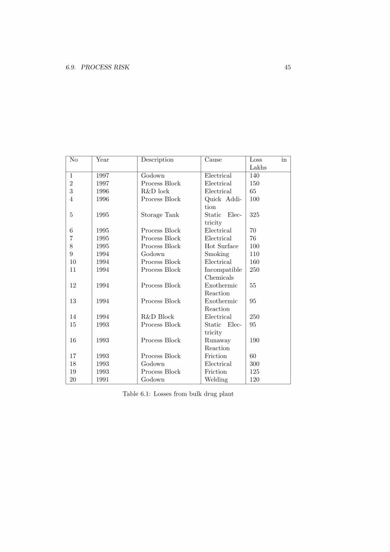
Following is the list of some of the major bulk drug losses(source LPA)Quick reviews of these incidences indicate that there are three significant
causes that triggered these accidents.
1. Inadequate process risk evaluation.
2. Inadequate engineering to cope up with likely deviations and the processdemands.
3. The human factor.
6.9 Process risk
When chemical substances undergo chemical reaction to yield products, a changeof potential energy is to be expected. When the sum of potential energies of theproduct is less than those reactants there is a net gain in the potential energy.This energy is invariably released to the surrounding environment in the formof heat. When the heat is not removed effectively the system temperatureraises and the reaction rate increases evolving more heat. At one particular
6.9. PROCESS RISK 45
No Year Description Cause Loss inLakhs
1 1997 Godown Electrical 1402 1997 Process Block Electrical 1503 1996 R&D lock Electrical 654 1996 Process Block Quick Addi-
tion100
5 1995 Storage Tank Static Elec-tricity
325
6 1995 Process Block Electrical 707 1995 Process Block Electrical 768 1995 Process Block Hot Surface 1009 1994 Godown Smoking 11010 1994 Process Block Electrical 16011 1994 Process Block Incompatible
17 1993 Process Block Friction 6018 1993 Godown Electrical 30019 1993 Process Block Friction 12520 1991 Godown Welding 120
Table 6.1: Losses from bulk drug plant
46CHAPTER 6. LOSSES OF THE PAST AND LESSONS FOR THE FUTURE
temperature (on set temperature of a runaway reaction) the reaction goes outof hand resulting in explosion and fire. A situation similar to this also occurswhenever the system uses highly reactive molecules, which decomposes violentlyresulting in fires and explosion at its decomposition temperature.
It is therefore necessary for the R&D chemist to identify the process risk atan early stage of process development to eliminate these areas. In assessment ofreaction chemical hazard, the rate of release of thermal energy is an importantparameters to be measured for a reacting system. If such an approach is notadopted, this area will be a blind spot for the entire operating period of theprocess. Today all over the world the thinking in process safety revolves arounddeveloping processes that are inherently safe to operate.
6.10 Design and engineering control
The chemical engineers are at a distinct disadvantage while designing batchprocesses which are extensively used in Pharma industry as against continuosprocess plant. Unlike the continuos process plant where the process parame-ters are fixed, the flow of chemicals are more are less known, the physical andchemical properties are well known, incase of pharma industry most of theseparameters are not known to the designers. The quantum of heat evolved dur-ing reactions, the quantum of gases that will get evolved are all unknown tothe design engineer. Apart from this the batch reactors are often used for sev-eral products and several operations, which makes it difficult to achieve properdesign. It is also necessary to discuss in detail with the process chemist. thefacilities that are required to be implemented for hazardous reactions, for termi-nation of reactions and isolation of reactors before the plant is laid out. Productrisk profile, engineering validations for safe operations should be well understoodand implemented.
6.11 Human factor
According to US environmental protection agency ”Action of operators reflectthe performance of organization and its management. Viewed from this per-spective, operator error, excluding willful negligence or malfeasance, are oftensymptoms and not really root causes. If an incident investigation program fre-quently assigns operator error and inadequate training as root causes, or if therecommendations frequently include disciplining operators or conducting moretraining, this may be a sign that the program isn’t identifying or addressing thetrue root causes. Like wise, if a safety management system relies on properlytrained operators to take correct action as the only line of defense against amajor disaster, then a facility that employs such as system is asking for troublein the long run because human make mistakes”. More often safety in processindustry is discussed inside meeting rooms with very little being taken to shopfloor. Safety should not the only an intellectual exercise but by understandingand training should be converted it into an instinct.
6.12. LESSONS FOR FUTURE 47
6.12 Lessons for future
The cause of loss / damage fall under two specific area
1. Those pertaining to Natural cause (Act of god perils) such as earthquakecyclones flood etc. It is necessary that design take that worst case scenariointo consideration when the units are located in the severe earthquake orcyclone zones. When units are located in stable zone or where inversionare possible it is to be realised that dispersion of any leak is likely to bemore hazardous than the other places.
2. Those pertaining to man made systems such as insufficiency in processrisk evaluation, layout, material selection design, and maintenance safetymanagement including training.
3. Large continuos process plants are less prone to accidents as they operateproven process with adequate instrumentation and process control. How-ever the severity of any accident is high since they unleash considerablequantity of flammable and toxic material.
4. Many of the loses in continuous process units have occurred due to loss ofcontainment resulting from unscheduled plant modification, lack of main-tenance and by passing instruments. Therefore the key area of concernfor these units are
• Proper layout (inter plant, intra plant, storage to plant, plant toutility and plant to control room)
• Material evaluation and corrosion monitoring
• Predictive and preventive maintenance including consequence of con-tainment failure estimates
• Up to date process control
• Fixed fire fighting system and early warning system
• Management of change protocol (process equipment modification)
• Emergency planning - Scenario based one
• Training - understanding of vapour cloud explosion, flash fire, BLEVEetc.
5. In case of medium sized batch process the scenario is different. The lossesrevolve around
• Shortcoming in process safety (Lack of RSST studies)
• Limited understanding of process hazard (”what if” situation withreference to process deviation)
• Inadequate design / layout/ maintenance (with reference to processundertaken)
• Lack of safety systems (relief systems, electrical area clarification, firealarms and fire fighting systems)
• Lack of safety management (Permit system , accident investigation,hazop studies, risk based audits)
48CHAPTER 6. LOSSES OF THE PAST AND LESSONS FOR THE FUTURE
• Lack of emergency preparedness (scenario based)• Lack of management of change• Lack of trained and qualified man power
6.13 Liability impacts of major disaster outsideits premises
After Bhopal disaster it is felt essential, therefore to provide for Mandatory Pub-lic Insurance for installations handling hazardous substances to provide mini-mum relief to the victims. Public liability insurance is limited to only relief on alimited scale of immediate relief would not prevent the victims to go to Courtsfor claiming larger compensation. Every owner shall take out, before he startshandling any hazardous substance, one or more insurance policies providing forcontracts of insurance whereby he is insured against liability to give relief as peract.
Any award for relief which exceeds the amount payable under the insurancepolicy as a relief measure, shall be met from the Relief Fund. In case the awardexceeds the total of the amount of insurance and the Relief Fund, the amount,which falls short of such sum payable shall be met by the owner.
Therefore it becomes essential to understand what are the views Courts haveon such incidences which would affect third party life, property and profit.
6.14 Court view
In a judgement, which affected the nearby population, the Supreme Court ruledthat An enterprises which is engaged in a hazardous or inherently dangerousindustry which poses a potential threat to the health and safety of the personsworking in the factory and residing in the surrounding areas owes an absoluteand non delegable duty to the community to ensure that no harms results toany one on account of hazardous or inherently dangerous nature of the activityin which it has undertaken.
The enterprise must be held to be under an obligation to provide that thehazardous or inherently dangerous activity in which it is engaged must be con-ducted with the highest standards of safety and if any harm results on accountof such activity, the enterprise must be absolutely liable to compensate for suchharm and it should be no answer to the enterprise to say that it had taken allreasonable care and that the harm occurred without any negligence on its part.
If the enterprise is permitted to carry on a hazardous or inherently dangerousactivity for its profit, the law must presume that such permission is conditionalon the enterprise absorbing the cost of any accident arising on account of suchhazardous or inherently dangerous activity as an appropriate item of its over-heads. Such hazardous or inherently dangerous activity for private profit canbe tolerated only on condition that the enterprises engaged in such hazardousor inherently dangerous activity indemnifies all those who suffer on account ofthe carrying on of such hazardous or inherently dangerous activity regardless ofwhether it is carried on carefully or not
This principle is also sustainable on the ground that the enterprise along hasthe resource to discover and guard against hazards or dangers and to provide
6.14. COURT VIEW 49
warning against potential hazards. Where an enterprise is engaged in a haz-ardous or inherently dangerous activity and harm results to anyone on accountof an accident in the operation of such hazardous or inherently dangerous ac-tivity resulting for example, in escape of toxic gas the enterprise is strictly andabsolutely liable to compensate all those who are affected by the accident
The measure of compensation in such cases must be correlated to the mag-nitude and capacity of the enterprise because such compensation must havedeterrent effect. The larger and more prosperous the enterprise, greater mustbe the amount of compensation payable by it for the harm caused on account ofan accident in the carrying on of the hazardous or inherently dangerous activityby the enterprise
50CHAPTER 6. LOSSES OF THE PAST AND LESSONS FOR THE FUTURE
Chapter 7
E-Waste Management - Suitablefor Indian condition
J.R.Mudakavi, P. ParthasarathyDepartment of Chemical EnggIndian Institute of Science,Bangalore
This presentation deals with the proposed pilot plant project on e-wastemanagement adoptable for Indian conditions to be located near Bangalore, Kar-nataka. Our country needs simpler, cost effective technology keeping in viewof maximum resource recovery in environmental friendly way. Awareness onE-waste is required among individuals, corporate houses, government officesand in particular children in schools on hazards and long term effects if landfilled. Take back policy on the equipments containing hazardous materials, themanufacturer’s responsibility and reverse logistics and immediate legislation arerequired for speedy implementation. The business model is based on good mate-rial management and decision making to optimize resource recovery of not onlythe entire systems, subassemblies and components but also recycling of met-als, plastics and glass. Various modules for the recovery are discussed with theequipments, test facilities, a laboratory and Effluent Treatment Plant. Cleanwork environment and safety of man, machine and material are the most im-portant in e-waste recycling.
7.1 Background
Electronic waste or e-waste is one of the most rapidly growing environmentalproblems of the world. In India, the electronic waste management assumesgreater significance not only due to the generation of our own waste but alsodumping of e-waste particularly computer waste from the developed countries,as they find it convenient and economical to export rather than recycle on theirown homeland. It is unfortunate to realize that the government, industries andconsumers as well, have taken very little steps to deal with this problem. E-waste contains thousands of different substances, some of which are toxic (Ref.Table 1) and creates serious environmental and hence health problem whendisposed or land filled indiscriminately. It is our responsibility to provide a
51
52CHAPTER 7. E-WASTE MANAGEMENT - SUITABLE FOR INDIAN CONDITION
clean environment and quality life for the present and future generations.We are trying to find an enterprise solution to the e-waste recycling technol-
ogy by developing state of art models, using simple and cost effective methods,suitable for Indian conditions. It is important to consider e-waste not as a wastebut as a resource for recovery and recycling. Initially the project will work onpilot plant scale of 1ton / day and scale up to 10 tons / day. Our primary con-cern is to develop indigenous technology by continues research & development,dissipate the technology among the entire country and at the same time abideby the environmental and social responsibilities.
7.2 Definition of e-waste
Electronic waste can be broadly defined as electronic equipments/ products,which have become obsolete due to: advancement in technology changes infashion, style and status nearing the end of their useful life. E-waste gener-ally consists of obsolete electronic devices such as computers, servers, mainframes, monitors, TVs & display devices, telecommunication devices such ascellular phones, calculators, audio and video devices, printers, scanners, copiersand fax machines besides refrigerators, air conditioners, washing machines, andmicrowave ovens. E-waste also covers recording devices such as DVDs, CDs,floppies, tapes, printing cartridges electronic components such as chips, pro-cessors, mother boards, printed circuit boards, industrial electronics such assensors, alarms, sirens, security devices, automobile electronic devices etc.,
7.3 Indian Scenario
There is an estimate that the total obsolete computer emanating from gov-ernment offices, business houses, industries and household is of the order of 2million. Manufacturers and assemblers in a single calendar year, produce around1200 tons of electronic scrap. It should be noted that obsolence rate of personalcomputers (PC) is one in every two years. The consumers find it convenientto buy a new computer rather than upgrade the old one due to the changingconfiguration, technology and the attractive offers of the manufacturers. Due tothe lack of governmental legislations on e-waste, standards for disposal, propermechanism for handling these toxic hi-tech products, mostly end up in land-fills or partly recycled in a unhygienic conditions and partly thrown into wastestream.
7.4 Take Back
Manufacturers and distributors of electronic equipment must take financial /physical responsibility for their products not only throughout the product life-cycle, but also take it back at the end of the life. The manufacturer respon-sibility must include: Reduced use of hazardous materials in manufacturing;Collection, disassembly, reuse and recycling of discarded electronic equipmentto the highest degree practicable; and Requirements that recycling is done inan environmentally sound manner. The electronics industry should graduallyreduce the use of toxic components that are dangerous to human health or the
7.5. BUSINESS MODEL 53
environment (including lead, mercury, cadmium, brominated flame retardants,chlorinated solvents, and other hazardous materials).
7.5 Business Model
A typical business model (Fig.1) envisaged for E-Parisaraa, consists of variousmodules which includes test area, disassembly section, metal area, plastic area,glass area, effluent treatment plant and a well equipped laboratory. The entireoperations will be controlled with efficient management systems and are to becovered under ISO 9000 quality management system. E-Parisaraa also envis-ages ISO 14000 implementation for both internal and external environmentalmanagement system. Demanufacturing technology The main objective of E-Parisaraa demanufacturing technology is to encourage electronics equipmentsreuse and refurbish. Fig. 2 shows schematic representation of demanufacturingtechnology. The equipments that are not serviceable shall be disassembled andthe subassembly components such as hard disc drives, floppy disc drives etcshall be tested for its reuse. The equipments and subassemblies that are notserviceable shall be recycled to obtain useful metals such as copper, aluminum,Iron, silver, gold, plastics such as Acrylonitrille Butadiene Styrene(ABS), HighImpact Polystyrene(HIP), Poly Vinyl Chloride(PVC), Poly Ethylene(PE), PolyPropylene(PP) and glass. The hazardous components shall be suitably pro-cessed and disposed in secure landfill area. The systems and equipments thathave a useful life shall be donated for socially under privileged, needy schoolsand voluntary organizations.
7.6 Test Area
The system level testing provides the capability, necessary to test bulk of com-ponents such as PC, audio, video equipments, telecom equipments etc. Fig. 3shows schematic representation of Test Area. Testing is the primary tool, whichdetermines whether the equipment/ item has salable value in current testedstate or whether the item must be further reduced to its basic elements, whichincludes component disassembly. If the system is in working condition it iscleared for reuse for the needy. If the system test fails, the unit is cleared fordisassembly of its subassembly such as hard disc, floppy disk drive, CD drive,keyboard, cathode ray tube (CRT) etc. Such of those subassemblies that arein working condition shall be stored separately with appropriate labels, codingetc, for refurbishment and reuse. If the subassembly test fails it may be clearedfor components recovery if required depending on the salable value. If not theentire subassembly may cleared for recycle by destruction. The system leveltesting consists of visual product inspection, cathode ray tube device testing,computer power up testing, printer testing and miscellaneous electronic test-ing. Wherever necessary the data erasure to protect the intellectual propertycontained in the system shall be implemented.
54CHAPTER 7. E-WASTE MANAGEMENT - SUITABLE FOR INDIAN CONDITION
7.7 Metals Area
The materials from the test area shall be sorted into two streams. 1. PrintedCircuit Board (PCB) & Printed Wire Board (PWB) scrap 2. Complex scrapwhich includes hard disc, floppy disc etc. with the PCB and salable componentsremoved.
The PCB & PWB stream mainly consists of 70The solder, which invariably found in the bottom side of the PCBs shall
be recovered using mechanical means. Then PCB and PWB shall be cut intopieces by first stage shredding (Fig. 4a) to yield pieces of 1 sq inch size. Thisin turn further crushed by hammer mills to yield fine particles of size less than1mm. The powdered material shall be fluidized to separate the metals and non-metals part. Vibratory screen separators shall be used to separate the particlesof required size and the oversized shall be recycled back. Bag filters shall beused effectively wherever necessary to control the air pollution. Since the metalsare heat sensitive the necessary equipment shall be water cooled to control thetemperature rise.
The complex scrap shall be shredded initially followed by hammer mill topulverize to a size less than 1mm. The pulverized material undergoes magneticseparation for the removal of ferrous materials followed by eddy current separa-tors, which can separate non-ferrous etc. The non-metal part, which invariablycontains some percentage of metals shall be leached suitably to dissolve themetal components, filtered and neutralized. It is envisaged to have two shopfloor areas, one for mechanical processing and the other for chemical processing(Fig. 4b). The heavy metallic part separated after fluidisation shall be leachedappropriately in order to remove the respective metals and finally processedin electrowinning cells to plate out copper along with other trace metals. Acounter flow solution movement enables recycling of the leach solution with pe-riodic makeup by demineralised water the spent solution is taken into effluenttreatment plant. The metal leaching area shall be provided with appropriatefume exhaust facility followed with mild alkali scrubbing to facilitate clean workenvironment.
7.8 Plastic Area
The plastic processing area mainly handles some of the following types like Acry-lonitrile Butadiene Styrene(ABS), High impact polystyrene(HIP), Poly VinylChloride(PVC), Poly ethylene(PE), Poly Propylene(PP) which are separatedfrom the metal parts by air fluidisation or by any other separation techniques.The separated plastics will then go for identification and separation sectionwhere the conventional methods are used to check the type of plastic and it willbe sent for suitable recycler.
7.9 Glass Area
The glass area, which mainly handles CRT glass, will use specially designedequipment in such a way to defuse and release the vacuum. Fig. 6 shows theschematic representation of glass processing. The CRT glass shall be cut eitherby Oxy Acetylene flame torch or specially designed diamond saws in order to
7.10. LABORATORY 55
separate the front glass, frit glass, funnel glass, neck glass. The electron gun,which mainly consists of Stainless steel anode cathode plates and tungsten ele-ments, shall be separated manually using protective safety gears. The phosphorcoating on the inside of the front glass shall be removed in a closed chambersand-blasting machine. The phosphor shall be separated by suitable methodof filtration and collected in a container with hazard labels. This being a haz-ardous material, efforts are under way for recycle and reuse or safe disposalof this material. The cut glass component shall be sorted under visual/ ultraviolet light to detect the monochrome, color and other glass depending on thetint. The sorted glass shall be broken further cleaned, washed and screened toglass culets for recycle into glass industry. The hazardous components in entireprocess shall be continuously monitored and eliminated.
7.10 Laboratory
Sample preparation area where the materials from the customer shall be crushed,analysed on a small scale. The analysis of conventional volumetric and gravimet-ric procedure shall be adopted. For accurate metal analysis Atomic AbsorptionSpectrophotometer has been planned for procurement, which will also help inanalyzing trace elements in effluents.
7.11 Effluent Treatment Plant
The effluent from the process plant is sent to the effluent treatment plant. Theeffluent treatment plant mainly consists of three stages Neutralization Clari-fication Purification and Recycling The process is shown schematically in Fig.7.
7.12 Risk factors
The greatest risk factor anticipated in the Indian Scenario is the lack of aware-ness among the general public, lack of proper collection procedure, reverse lo-gistics, lack of guide lines for handling, transportation and storage of e-wasteto the recycle premises, since these factor can affect the quantity requirementsfor recovery. This project has to compete with those of the unorganized sectorsand scrap dealers, who have been processing the e-waste in unscrupulous man-ner and polluting the environment. It is imperative that the government shallbring in suitable guidelines and legislations to prevent unauthorized recyclingand disposal of e-waste in the country.
7.13 Environmental, Health and Safety
• Every effort will be made for resource recovery and use of end productsand landfill of hazardous components.
• Process developed shall be environmentally safe from the point of view ofair and water pollution.
56CHAPTER 7. E-WASTE MANAGEMENT - SUITABLE FOR INDIAN CONDITION
• Every effort will be made for continuous monitoring of air pollution andground water pollution to evaluate long-term impacts.
• To ensure continuous protection of human health and environment.
• Implement sustainable development, consideration of EHS will have over-riding priority.
• Leadership in environmental management by minimizing impact on em-ployees, general public and customers.
Table 7.1: Hazardous Materials in E Waste
Substance Occurrence in e-waste
Environmental andHealth relevance
Polychlorinatedbiphenyls
condensers, trans-formers
Cause cancer, effects onthe immune system, re-productive system, ner-vous system, endocrinesystem and other healtheffects.
fire retardants forplastics (thermo-plastic components,cable insulation)TBBA is presentlythe most widelyused flame retar-dant in printedwiring boardsand covers forcomponents
can cause long-term pe-riod injuries to healthacutely poisonous whenburned
Chlorofluorocarbon(CFC)
cooling unit. combustion of halo-genated substances maycause toxic emissions.
PVC (polyvinylchloride)
cable insulation Burning of cables may re-lease chlorine, which isconverted to dioxins andfurans.
Arsenic small quantities inthe form of galliumarsenide withinlight emittingdiodes
acutely poisonous and ona long-term perspectiveinjurious to health
Barium getters in CRT May develop explosivegases (hydrogen) if wetted
Beryllium power supply boxeswhich containsilicon controlledrectifiers, beamlinecomponents
P.ManoharanHealth, Safety and Environment ManagerIndian Additives LimitedManali, Chennai - 600 068
8.1 Introduction
Rapid industrialization has brought in many changes. Positive changes areincrease in gross domestic Products, overall improvement in quality of life etc.It has also brought in some negative effects such as the serious consequencesdue to industrial accidents.
From factories to offices, construction sites to local authorities, health andsafety is more than just a legal requirement. It is a good business sense. A safer,healthier workforce leads to higher morale and can lead to improved productivityand reduces risk.
The field of industrial health and safety has undergone significant changeover the past two decades. There are many reasons for this. Some of theprominent include the following:
• Technological changes that have introduced new hazards in the work place
• Proliferation of health and safety legislations
• Increased pressure from assertive regulatory agencies
• Realization by industrial executives that a safe and healthy work place istypically a more productive work place
• Skyrocketing health care and workers compensation costs
• Increased pressure from environmental groups and the public
• A growing interest in ethics and corporate responsibility
• Professionalisation of health and safety occupations
• Increased pressure from the labour organizations and employees in general
59
60 CHAPTER 8. SAFETY MANAGEMENT
• Rapidly mounting costs associated with product safety and other types oflitigation
All of these factors, when taken together, have made the safety managementas more challenging and more important than it has ever been for the industries.Safety management in industry consists of the following key elements:
Visible management commitment to safety: The management of safety hasbeen seen as an essential part of management’s daily responsibilities, alongwith others such as quality, production, cost control, profitability and morale.Management can show commitment to safety by:
• Applying a high priority to safety in the planning and evaluation of allprojects and operations.
• Taking a personal interest in accidents, their investigation and follow upand in the welfare of the people concerned.
• Staffing safety department with experienced and competent personnel.
• Setting a good example
• Management participation in safety inspections and safety meetings
• Promoting safety in public, during company meetings and in publications
• Always including safety instructions when issuing day to day instructions
• Including safety as a priority item on the agenda at staff and managementmeetings
• Safety should feature prominently in business plans and performance re-ports
• It is management’s responsibility to ensure that all employees are properlyequipped and trained and to motivate them so that all employees want towork safely.
8.2 Safety policy
An effective safety policy will be concise, easily understood and available to everyone. Each company has to develop its own policy to meet its own particularrequirements and should be based on the following philosophy:
• Acceptance of the principle that all injuries can and should be prevented
• Management at all levels is responsible for preventing accidents
• Safety should have equal status along with other primary business objec-tives
• The need to provide properly engineered facilities and safe procedures
• All operational exposures which may result in injury should be safe guarded
• It is necessary to train all personnel to work safely
8.3. SAFETY TO BE A LINE MANAGEMENT RESPONSIBILITY 61
• A safe operation is usually an efficient operation
The policy should be distributed to all personnel as well as displayed onnotice boards, and published in house journals.
8.3 Safety to be a Line Management Responsi-bility
In some companies the belief may still exist that the responsibility for safety liesmainly with the safety department, or the safety officer. This is quite wrong.The safety department has a vital role to play as a specialist adviser but it canbe neither responsible, nor accountable for safety policy or performance. Thisresponsibility lies with the line management from chief executive to every levelof supervisor.
• All responsibilities and accountabilities for safety in the line must beclearly defined in job descriptions.
• The organisation must encourage a two way flow of information and ideas.So that all personnel understand that their input is necessary.
• Each manager and supervisor must demonstrate personal commitmentto the safety program by good example and by reacting promptly andeffectively to:
– Poor safety performance
– Excellent safety performance.
– Lack of standards of safety practices
– Lack of adequate safety programme, plans and objectives
– Safety reports and their recommendations
– Unsafe working conditions and practices
– Inadequate training or instruction
– Accident and incident reports and the action needed to prevent re-currence.
– Ideas and suggestion for improving safety.
It follows that staff appraisal procedures should include, in a meaningful andincisive manner, consideration of each manager’s and supervisor’s safety atti-tudes and performance. All personnel should be involved in the safety effortand must be made aware of their role in the safety organisation and what theirown responsibilities are.
8.4 Safety officers
Too often, managers have left safety matters to the safety department. However,no safety department can in any way be responsible or accountable for whathappens under someone else’s management. Its role can only be to advise,coordinate and monitor. To do so effectively, it must contain adequate expertise
62 CHAPTER 8. SAFETY MANAGEMENT
and be freely available to management at all levels. It has to be kept sufficientlyaware of the company’s commercial and technical objectives to allow it to:
• Guide management on safety policy, audits and accidents reporting andinvestigation.
• Provide technical safety information and experience.
• Give guidance on, and participate in preparation of instructions, trainingand exercises.
• Coordinate the monitoring and appraisal of safety performance
• Guide management on contractor safety management
The credibility of safety staff is of extreme importance and is a key factor inthe Safety Management Programme.
8.5 Safety standards
Safety can be separated into two components: firstly in design, equipment andprocedures and secondly, people’s attitude and their behaviour towards safety.Key factors in establishing these standards, which can be operating procedures,safety rules and regulations and standards of house keeping are:
• They should be written so that they can be easily understood.
• They must be accessible to all personnel
• Standards and procedures must be practicable and reasonable.
• Standards will be more acceptable to people
• Standards should be adequate to cover changing circumstances taking intoaccount relevant safety experiences both of the company itself and of othercompanies.
The success of standards depends upon the extent to which people abideby them. If standards are breached without correction, the credibility of thatstandard is in doubt.
8.6 Techniques to measure safety performance
The lost time accident (LTA) frequency rate is one measure of safety perfor-mance. The method is similar to that used by many other industries, andenables direct comparisons to be made. However, the relevance and usefulnessof LTA frequency rate is reduced as the total number of LTAs becomes verysmall, or if the operation is small and the number of LTAs are close to or zero.In such situations it cannot be relied upon as an indicator of safety performanceand a more sensitive tool is needed. Many companies already record non- LTAsand plan to move towards recording near misses and unsafe practices. This willindicate the relationship between the seriousness of the injury and the unsafepractices that caused the incident. By aiming our efforts at unsafe practices,
8.7. SAFETY TARGETS AND OBJECTIVES 63
one is working directly on preventing accidents ever happening. This is a pow-erful tool for every one to use, bearing in mind that the main purpose of anymeasurement technique is to improve performance by eliminating accidents.
8.7 Safety targets and objectives
A steady annual reduction should be achievable proving the established policiesare kept alive, and people remain committed to safety. The setting of targetsthat are seen to be both reasonable and achievable is essential. Typically acertain percentage annual reduction in frequency rate can be a target, while thelong term objective is to achieve an accident free performance.
Management should develop plans to achieve the long term safety objectives.Each department should develop its own safety plans and targets with a writtenschedule. The details of these programmes can form a useful basis for discussionat safety meetings.
Targets should be quantified wherever possible and could include the follow-ing:
• Instructions, rules, procedures or documents to be written or received witha completion schedule.
• Frequency and number of safety committee meetings and other safetymeetings
• Frequency and number of inspection and audits of the different types
• Frequency of contingency plan rehearsals involving company and externalresources
Staff reports include safety related targets or tasks against which perfor-mance can be measured. Performance improvements should not be demandedwithout giving individuals the tools to do the job, such as training and properequipment.
8.8 Audits of safety standards and practices
Most companies already have safety inspection and audit programmes, usuallyconcentrating on equipment and procedures, where supervisors, managers, rep-resentatives from the safety department and sometimes outsiders audit to afixed schedule, often with months, if not years, between audits. Efforts shouldbe made to increase the effectiveness of auditing by structuring the content,coverage and participation of each audit and by the adoption of procedures tomonitor timely implementation of audit recommendations.
In addition, there should be auditing for unsafe acts and conditions. Thiscan be undertaken whenever a manager or supervisor enters a work area. Itinvolves looking at people, what they do, how they do it, what they wear; andat tools, equipment and the general work area. It is potentially a very powerfultool because correction of unsafe acts and conditions at frequent intervals willprevent accidents and recording them will be a sensitive yardstick of safetyperformance.
64 CHAPTER 8. SAFETY MANAGEMENT
8.9 Safety training
A safety programme requires a concentrated effort to ensure staff is made fullyaware of the programme and of the philosophy behind it. Achieving acceptanceof the philosophy down the line is the biggest challenge for management and amajor programme of presentations, work shops and discussions will be needed.Dissemination throughout the company can be achieved rapidly by these means,but informal discussion and briefing between the supervisor and subordinate isequally necessary. Consistency of approach is essential so that everybody getsthe same message. Senior management should participate in these presentationsthus demonstrating their commitment. The emphasis must be on changing peo-ple’s attitudes to safety and demonstrating how personnel behaviour is the mostimportant factor in preventing accidents. Existing technical training should ofcourse be continued and specific safety aspects incorporate into the programme.Management should plan and monitor progress through the established trainingprogrammes for each individual thus ensuring the person is fully equipped todo his job.
8.10 Investigation and follow up of injuries andincidents
Incident investigation procedures are already well established in many compa-nies but too often the main objective of the investigation, to prevent it happen-ing again, is sacrificed in the search for the person responsible for the accident.Thus people become defensive and it becomes difficult to establish the facts.
The responsibility for incident investigation lies with line management.One should be aware that the questions ’what caused the accident?’ and
’who is responsible?’ should not be confused. Even though it may be estab-lished as a matter of fact that a certain accident was directly caused by anindividual, it is often too easy to simply put the blame on the individual con-cerned. The matter should rather be viewed in the context of the wider sphereof management’s own responsibilities. For instance, the individual concernedmay have been inadequately placed, instructed, supervised or trained; he mayhave been unfamiliar with the procedures, or the procedures may have beenunsuited to the job in hand.
There are a number of guidelines for accident investigation:
• Investigate promptly
• Involve those who have a real knowledge of the work situation
• Collect and record facts, including organisational relationship, similar oc-currences and other relevant background information.
• Have as the objective ’to prevent a similar incident happening again’
• Identify all causes
• Recommend corrective actions
All recommendations should be followed up and any lessons learned shouldbe communicated as widely as possible.
8.11. MOTIVATION AND COMMUNICATION 65
8.11 Motivation and communication
The success of a safety programme depends on people - how they are motivatedand how they communicate with each other. One of the major keys to successlies in establishing communication with people at all levels. Methods may in-clude written circulars, reports, news sheets, promotional activities, incentiveand / or reward schemes, personal contact and, most successful of all, structuredsafety meetings at the work place level where every one can become involved .Safety meetings will be more productive and motivating if a member of a groupunder the guidance of management is asked to lead the meeting, having firstbeen given the framework of the subjects for discussion and what the discussionhopes to achieve. Where contractors are part of the work group they shouldalso be included. Conclusions and concerns should be written down and actedupon. The active participation of all staff in safety meetings should be regardedas a long term objective. The main objectives of safety meetings are to:
• Seek ways to eliminate unsafe practices
• Convey safety information to all employees
• Obtain contributions from employees
• Get participation in and commitment to the safety programme
• Encourage communication and debate
• Resolve any concerns or problems that emerge.
Feedback should be given as soon as possible so that open action items donot accumulate. In addition to structured safety meetings, supervisors, whenconsidering forthcoming jobs with their subordinates, need to discuss all therelevant safety aspects by means of a toolbox talk or pre job meeting.
A major management objective at both safety committees and safety meet-ings should be to find out how people at all levels perceive the safety effort andwhether safety information and messages are understood in the way they aremeant. Feed back must be encouraged if people are to remain motivated.
What is a Safety and Health Management Program and where does it fitinto management system?
Management leadership and employee involvement are complementary. Man-agement leadership provides the motivating force and the resources for organiz-ing and controlling activities within the organization. In an effective program,management regards worker safety and health as a fundamental value. Em-ployer involvement provides the means through which workers express theirown commitment to safety and health, for themselves and their fellow workers.
If one want to reduce incidents and their related costs, everyone must place asmuch emphasis on safety and health issues as they place on other core manage-ment issues, such as production, sales, and quality control. To be most effective,safety and health must be balanced with, and incorporated into, the other corebusiness processes. There is a certain amount safety ”culture” and componentsof an effective safety and health program that must exist to accomplish thistask.
66 CHAPTER 8. SAFETY MANAGEMENT
”Safety is # 1”, or ”Safety First” may sound good, but in reality, safetycan not be considered separately from other aspects of the business. Rather, itmust become a basic value and not a priority for your company. One shouldconsider changing ”Safety is #1”, and ”Safety First” to ”Safe production is ouronly standard.” Or something similar. The point is that we are trying to createa safety culture that will be valued by all employees. This emphasizes the ideathat it’s fine to produce as hard and as fast as possible, which in most instancesis the case, as long as it can be done safely without taking short cuts.
To get an idea of where safety and health system fits into the workplace,answer the questions below:
Safety and health are an integral part of our operations. Yes, No, Don’tknow
Teamwork is apparent in all parts of the organization. Yes, No, Don’t knowManagers and supervisors are out on the floor frequently and always observe
the company safety and health rules. Yes, No, Don’t knowEmployees are encouraged to identify safety and health hazards and correct
them on their own. Yes, No, Don’t knowEmployees have full and open access to all the tools and equipment they
need to do their job safely. Yes, No, Don’t knowIf you were able to answer YES to each question, you may be on your way to
developing a safety. If you answered any question with No or Don’t know, youneed research and understand the opportunity for improvements in your safetymanagement system.
Chapter 9
Hazard and Operability Study
K S S RaghavanDirector- Safety & EnvironmentShasun Chemicals And Drugs LtdChennai - 600042
9.1 Introduction
Safety in designing the chemical plants relies on the application of various codesof practice and / or design codes which are the result of long years of experienceand knowledge of professional experts. It has become increasingly clear in therecent years that although the codes of practice are valuable it is necessary tosupplement them with an imaginative anticipation of hazards.
The need to check the design for errors and omissions has been recognised fora long time and this has been done individually for their own field of expertise.This approach was also found to be inadequate at times when some hazards arelikely to result from the unexpected interaction of a seemingly safe componentsor operation under exceptional conditions. If such interactions in new designsare tobe studied then combined skills of experts are required. Such combinedknowledge and informed imaginations can be used to anticipate whether theplant will operate as intended under all circumstances.
The HAZOP (or) hazard and operability study is a formal procedure devel-oped by ICI at UK nearly four decades ago to identify hazards in a chemicalprocess facility. This procedure has been proved to be effective in identifyingthe hazards and is well accepted by the industry.
9.2 Principle
The fundamental idea is to let the mind go free in a controlled fashion in orderto consider all the possible ways in which process and operational failures canoccur.
On most of the occasions after an accident or when operational difficultiesare encountered investigation are carried out to find out the cause or causes.
67
68 CHAPTER 9. HAZARD AND OPERABILITY STUDY
During such investigations certain faults in the design operation or equipmentare identified which were not obvious during the design and erection phase.
While imagination is necessary in the study the team members must beguided and stimulated in a systematic and creative manner to cover all parts ofthe plant and all possible malfunctions and mal operations are foreseen.
This is achieved by taking full description of the process and systematicallyquestioning every part to find out how deviations from the design intention canoccur and how such deviations can lead to hazards.
The questioning is done on every part of the design. The questions are basedon the guidewords which are derived from method study techniques. These guidewords ensure that the integrity of each part of the design is tested and explorethe deviations. These deviations are considered to decide how it could be causedand if caused what would be the consequences.
Certain causes may be un realistic and hence it is rejected. Similarly some ofthem may be trivial and not considered further. However such of those deviationwith causes that are conceivable and consequences that are hazardous are notedfor remedial measures
After listing such relevant deviations and consequences, it is examined withthe set of controls that have been built into the system and its adequacy isevaluated.
Based on the findings further recommendations are formulated to improvethe system.
After completing one part then the next part is taken for study and thisprocess is repeated till the whole plant has been studied.
Although the approach may appear to be systematic the success or failureof the study depends on:
1. the accuracy of drawings and other data used as the basis for the study
2. the technical skills and insights of the team
3. the ability of the team to use the approach as an aid to their imaginationin visualising the deviations, caused and consequences.
4. The ability of the team to maintain a sense of proportion, particularlywhen assessing the seriousness of the hazards.
It is necessary that the participating team uses certain terms in a preciseand disciplined manner. The important terms are
Intention : It defines how the part is expected to operate. This can be eitherdescriptive or diagrammatic. It can be a flow sheet or line diagram.
Deviation : Denotes the departure from the intention which are discoveredby the application of guide words.
Causes : The reasons why deviations might occur. When the deviation isshown to have a realistic cause it can be treated as meaningful.
Consequences : These are the results of the deviations should they occurHazards : These are the consequences which can cause damage, injury or
loss.Guide words : Simple words which are used to qualify the intention in order
to stimulate the thinking and discover deviations.
9.3. PROCEDURE 69
9.3 Procedure
The procedure for hazop will contain the following
1. Define the objectives and scope
2. Select a team
3. Prepare for the study
4. Carry out the examination
5. Record and follow up
The objectives and scope of the study must be clearly defined some of thereasons for a study are
1. to check and verify a design
2. to check up the adequacy of parameters prior to start up
3. to improve the safety of existing facilities
4. to ensure integrity of safety of operations during changes of equipment,operational procedures etc.
The HAZOP is generally carried out with members from multi disciplinaryskills . There are two types of team members I) those who will make a technicalcontribution and ii) those who extend supporting role.
The technical members should possess detailed knowledge and experience ofthe way the plant is intended to work. It is essential that the team consistsof people capable of answering majority of the questions with out reference tofurther expertise.
The team is generally composed of experienced plant, mechanical, R&D,technical, instrumentation and safety professionals. One person must be namedas the leader who will be able to lead the discussion and must be experiencedwith the HAZOP procedure as well as the chemical process under review. Oneperson must be assigned the responsibility of recording the results. Number ofsoftwares are available for this.
The meeting duration can be from few hours to few weeks depending uponthe size, magnitude of the plant and the scope of the study. A complete hazopstudy requires a large investment in time and effort but the value of the resultis well worth the effort.
Before commencement of the hazop study the following must be available:
1. detailed process information
2. process flow diagrams (PFD’s)
3. process and instrumentation diagram (P&ID’s)
4. equipment specifications including material of construction
5. mass and energy balance
6. typical properties of chemicals used.
70 CHAPTER 9. HAZARD AND OPERABILITY STUDY
7. Known hazards / critical parameters of the process
The hazop procedure uses the following steps:
1. Begin with a detailed flow sheet. Break it into number of process units (ex : reactor, storage tank, centrifuge etc.)
2. Choose a study node ( vessel, line)
3. Describe the design intent of the study node ( ex. Vessel - 1 is designedto store alcohol and provide it on demand to reactor )
4. Choose a process parameter ( flow, level, temperature, pressure, concen-tration)
5. Apply guide word to the process parameter to suggest possible deviations.A list of guide words is shown in Table 1). Some of the guide words andprocess parameter combination are meaningless as shown in table 2.
6. If the deviation is applicable determine possible causes and note any pro-tective systems available.
7. Evaluate the consequences of the deviation
8. Recommendations ( what, by whom? When?)
9. Record all information
10. Repeat steps 5 to 9 until all applicable guide words have been applied tothe chosen process parameter
11. Repeat steps 4 to 10 until all applicable process parameters have beenconsidered for the given node.
12. Repeat steps 2 to 11 until all the study nodes have been considered for agiven section and then proceed to next section and follow the procedure.
It is imperative that the whole team should have a positive and constructiveattitude to the study since the success depends on the imaginative thinking ofthe members.
The preparatory work depends on the size and complexity of the plant. Withcontinuous plants the preparatory work may be somewhat less since the existingflow sheets, P&I’s contain adequate information. With batch process plants thework may be more extensive. In addition to drawings it is necessary to knowthe sequence of plant operations, batch instructions, logic diagrams etc.
With complicated or proprietary type of equipments, the work may be moreelaborate since availability of information may be limited.
The examination sessions are highly structured and the team leader willbe controlling and guiding the discussion following a pre-determined work plan.The team leader must initiate the discussion and guide the process with probingquestions. The team should not only provide the technical answers but must beencouraged to be creative and think of all deviations and possible hazards
As hazards are detected, it must be understood by the team and the solutionhas to be found out. This may be immediate or it can also take time allowingthe members to think.
9.3. PROCEDURE 71
Actions to contain hazards generally can be classified into the following fourtypes.
a. change in the process ( receipe, raw materials, etc.) b. change in processconditions ( pressure, temperature etc.) c. alteration to the physical design d.change in the operating method
It is important to consider all the aspects and decide on the best actionWhen choosing between a number of possible actions it may be useful to put
them in the following categories.Those actions which remove the cause of the hazard Those actions which
reduce the consequencesIt is generally better to remove the hazard and this may be possible if the
study is undertaken at the design stage when these can be incorporated withoutmuch additional expenditure.
In the event that there are no reasonable prospect of removing the hazardthen the team has to consider actions to be taken to protect people and plant.
The advantage to this approach is that it provides a more complete identifi-cation of hazards including information on how hazards can develop as a resultof operating procedures and operational upsets in the process. When a detailedHazop is performed it is felt that process operate better with less down time,less waste and employees are more confident in the safety of the process. This ismainly due to the fact that most of the conceivable hazards have been thoughtof and protection has been built into the system.
Hazop is tedious to apply, requires considerable time. But when it is per-formed well, it ensures the safety of process.
72 CHAPTER 9. HAZARD AND OPERABILITY STUDY
Guide words Meaning CommentsNo, not, none Complete negation
of intentionNo part of the design in-tention is achieved butnothing else happen
More, higher,greater
Quantitative in-crease
Applies to flow rate andtemperature and to activ-ities such as heating andreaction
Less,lower Quantitative de-crease
Applies to flow rate andtemperature and to activ-ities such as heating andreaction
As well as Qualitative de-crease
All the design and operat-ing intentions are achievedalong with some addi-tional activity such ascontamination of processstreams
Part of Qualitative de-crease
Only some of the designintentions are achieved.some are not
reverse Logical opposite of Applicable to activatessuch as flow or chemicalreaction
Other than Complete substitu-tion
The original intention isreplaced by something else
Sooner than Too early or inwrong order
Applies to process steps oractions
Later than Too late or inwrong order
Applies to process steps oractions
Where else In additional loca-tions
Applies to process loca-tions or locations in oper-ating procedures
Table 9.1: Guide words used for the hazop procedure
Process pa-rameter
NoNotNone
More/Higher/Greater
Less/Lower
Aswellas
Partof
reverse Otherthan
Sooner/faster
Later/slower
Whereelse
Flow x x x x x x x x xTempe-rature
x x x x
Pressure x x x x xConcentration x x x x x x x xPH x x x xViscosity x x xstate x x x
Table 9.2: Valid guide words and process parameter combination for processlines ( x’s represent valid combinations)
9.3. PROCEDURE 73
Process pa-rameter
NoNotnone
MoreHigherGreater
LessLower
Aswellas
Partof
reverse Otherthan
Soonerfaster
Laterslower
Whereelse
Level x x x x x x x x xTempe-rature
x x x x
Pressure x x x x xConcentration x x x x x x x xpH x x x xViscosity x x x xAgitation x x x x x x xVolume x x x x x x x xReaction x x x x x xState x x x xSample x x x x x x
Table 9.3: Valid guide words and process parameter combination for processvessels ( x’s represent valid combination )
74 CHAPTER 9. HAZARD AND OPERABILITY STUDY
Chapter 10
Safety in Automobile Industry
J.YuvarajAssistant Manager - SAFETYAshok Leyland, Unit -1Hosur - 635 126 Tamil Nadu
10.1 introduction
Workplace Safety management has come a long way in the history of Indianautomobile industry. Safety as a value added function; is a dynamic functionin the day to day administration in continuously improving the systems andprocedures to ensure a risk free work environment. A work place is said to besafe only when the worker feels that he enjoys a total freedom from injury atworkplace.
The development of the workplace safety and health to workmen and to thosewho may be affected by the operations of a plant has taken place in differentstages:
1. Enforcement of factory legislations. 2. Compliance to factory and otherlegislations. 3. Reaction management to evolving risks. 4. Proactive man-agement through risk assessment and mitigation techniques. 5. Total safetymanagement (or) total loss control techniques (which encompasses all the aboveaspects)
Any management initiative unless it is top driven and lacks total commit-ment and involvement of all the functions of an organization does not yield thedesired results.
This applies to occupational health and safety management also.The automobile industry is both technology and people intensive. Over a
period of time the technology has limited the skill requirement of a worker inthe manufacturing process and this de-skilling mainly aimed at enhancing thequality standards demanded by the rapidly changing market. Correspondingwork place risks are not considerably reduced in the process. Unsafe acts stillcontinue to contribute to more than 90
Occupational Health related issues still exist (in some cases become a com-plex issue) as newer chemicals and processes get introduced in the manufacturing
75
76 CHAPTER 10. SAFETY IN AUTOMOBILE INDUSTRY
chain or process.Customers want products that are produced through processes that has min-
imum or no environmental impacts or from those that do not employ childlabour, or any resource that has been exploited in the manufacturing process.In short to day industry has to demonstrate that it is a socially responsibleentity to the world at large.
10.2 Industry specific risks
Major Sources of occupation health and safety risks common to an auto industrycan be from:
Material Handling Machining Assembly Hazardous process, handling of chem-icals etc. Services (like out of turn maintenance, contract work etc.)
Material handling alone contributes to around 50For e.g. - handling a small component that has sharp edge resulting in a cut
injury (and) an overhead equipment failure resulting in s head injury leading tofatal injury.
Machining activities contribute the next higher rate say around 20 to 25For e.g.: holding a rotating component with gloved hands, by passing of
two hand safety switches, removing the guards and exposing to moving parts,short cuts in clamping and machining, not using the full compliments of safetyfeatures provided in the machine etc.
Other health risks can be:Noise Heat Dust and fumes Toxic Vapours Toxic liquids Gases Cryogenic
material ElectricityThese health risks pose a threat to the workers health after prolonged expo-
sure and many a time the worker does not know the impacts of such exposures.Assembly activity contributes to around 10 to 16For e.g.: improper lifting methods, wrong/worn-out tools and equipment,
working at uneven phase etc.Hazardous process, handling of chemicals etc contribute rarely to an accident
record, but in the event of an occurrence of one the resultant severity is boundto be very high.
For e.g. ingestion of chemicals, burn injuries, scalding, exposure to extremetemperatures etc.
Heat treatment, metal finishing, painting, are some of the activities wherethe potential for risk to health and bodily injury is very high.
Apart from the above another major area where accidents occur is the outof routine activities which is mostly done by contract workers or outsiders mostof the time.
For e.g. roof cleaning and repair, white washing, premises maintenance etc.The Total loss control or total safety management initiative plays an essential
part in the overall management system of an organization to keep the occurrenceof accidents and incidents under control.
The TLC involves many stages with management objectives drawn from:Legislations Standards Industry guidelines and best practices. Company’s
own bench marks.Legislative requirements lay down the basic foundation for the installation
and running of a factory.
10.2. INDUSTRY SPECIFIC RISKS 77
For e.g. Indian Factories Act, 1948 and the TamilNadu Factories Rules, 1950Standards like ISO 9000, QS 9000, and ISO 14001, OHSAS 18001 etc are
international standards which help in establishing systems and procedures.(Ashok Leyland has been certified for all the above except OHSAS 18001
which is under implementation)Implementation of TLC is further taken up by:Establishing systems and procedures to identify the base risks and residual
risks in the operations of the plant.Analysis of past and present accident and incidents and to find out the root
causes and taking corrective and preventive action.Training and development to enhance the knowledge and skill of workmen,
contractors and make them competent in managing the risks associated in theirnature of work.
Keep the workmen involved with the management team in accident preven-tion through effective and continual campaigning.
Periodic auditing of the systems and procedures to track down the weaknessof the system and continual improvement.
Continuously monitor and measure performance against the set standardsand report to top management for review and take corrective actions and pre-ventive actions.
The success of a TLC programme largely depends on the top managementscommitment and continued support for the cause, and the roles and responsibil-ities down the line in the organization well understood and executed to reach thedesired goals, and last but not the least the TLC programme must be clearlyunderstood by each workmen in the organization that it is his life that is atstake which the programme aims to protect.
78 CHAPTER 10. SAFETY IN AUTOMOBILE INDUSTRY
Chapter 11
Reliability & Safety
A.Pio FernandezSenior Safety OfficerAshok Leyland
11.1 Reliability
The probability of an item operating for a given amount of time without failure.More generally, reliability is the capability of parts, components, equipments,products and systems to perform their required functions for desired periods oftime without failure, in specified environment and with a desired confidence.
Products failure ranges from failures that cause minor nuisance such as dam-age of bearing that creates noise to catastrophic failures like explosion in LPGbullet and Leakage of Ammonia etc.,
It is not surprising that Boeing was one of the first commercial companiesto embrace and implement reliability engineering, the success of which can beseen in the safety of today’s commercial air travel.
For a company to succeed in today’s highly competitive and technologicallycomplex environment, it is essential that it should predict the failures and haz-ards, the company is having and taking corrective action and preventive actionto control the hazard before anything happens.
11.2 Coverage
Reliability engineering covers all aspects of a product’ safe life, from itsIn manufacturing industries, to safe guard people and property reliability
engineering in maintenance support plays a vital role.Reliability Engineering in Ashok Leyland .. Equipment / component This
system is basically followed in our Maintenance activity to predict the failuresand replace the equipment / component in critical areas to prevent any ma-jor breakdowns / accidents which ultimately result in different types of losses.Safety critical parts where the system is followed: a. Overhead equipments b.Pressure vessels c. Hazardous material storage and use. d. High energy instal-lations. Detailed matrix was prepared for all critical equipments based on the
79
80 CHAPTER 11. RELIABILITY & SAFETY
previous history of failures and the equipment life given by the supplier. Pre-ventive Maintenance is a basic tool available to replace the critical parts beforethe occurrence of any accidents / failures.
The term ”reliability” refers to the probability that a system will perform apreviously defined mission without failure.
11.3 Application of Reliability to Safety
The relationship between reliability and safety is obvious since generally a morereliable system will be a safer one. As in any other systems design objective,there may be limitations to obtain a high degree of reliability. (such as technol-ogy, finance, operations etc) To help crystallize the application of reliability tosafety, consider the following generalizations:
1. Any two or more operations, events or devices that perform the same(safety) function with in a system may be considered redundant (or parallel)operations, events, or devices.
Eg: A guard on a power saw may eliminate 95% potential accidents. Safetyinstructions and motivation may eliminate 98 % of potential accidents. In asense these are parallel efforts on the same problem.
Figure 11.1: Reliability computation
R(S) = 1 - [(1-R(A1)] [(1-R(B2)] = 1- [(1-.95)][(1-0.98)] = 1- (0.05)(0.02) =1 -.001 = 0.999 i.e., Probability of accident is 0.001 or 1 in 1000 cases
2. Any two or more operations, events, or devices, all of which are required toprevent a given situation or accident, should be considered as series operations,events, or devices.
Eg; If a fire could start either from smoking or static discharge in a petroldispensing unit, the prevention of these two events could be considered in series.It is important to distinguish between reliability and unreliability at this point.If the reliability of the system is dependent upon the non-occurrence of a fire,the reliability of the components would be the probability that each preventedfire. For example, if the probability of a fire not starting in a given time periodby smoking and static electivity discharge are 0.99 and 0.98 respectively, thenthe reliability of the system
R(S) = R(A) * R(B) = (0.99) * (0.98) = 0.9702 i.e the probability of accidentis 0.0298
3. The relationship between configuration reliability and system safetyEg: Fault tree analysis Event tree analysis
11.4. CONCLUSION 81
Advantages: 1. Optimum preventive replacement. 2. Better informationabout the types of failures experienced by the parts and systems that aid design,research and development efforts to minimize these failures. 3. Establishment ofwhich failures occur at what time in the life of a product and better preparationto cope with them.
Reliability Engineering in Ashok Leyland .. EmployeesThe analysis of the time, location, age, nature of injury were made by taking
into account the past two years accident details and the results found in theanalysis was detailed below.
Time of Accident: Inference: High probability in 10 - 11 AM & 7 - 8 PMAccident Agencies: Inference: Agents ”Material” & ”Tools / cutters” are
having high accident probabilitiesAccident Cause: Inference: Causes ”Fall of Object”, ”Hit against stationary
object”, ”Caught between object” and ”Hit by a moving object” are havinghighest probabilities
Body Part Injured: Inference: Left eye, left thumb & Right middle fingerare displaying higher injury probability
11.4 Conclusion
Reliability engineering techniques can be used for study of human behaviorunder controlled conditions and machinery / equipment to predict the failuresfrom past data (history of events). Prediction provides for adequate and rightamount of redundancy planning in building a ”system safety” rather than a”safety system.”
11.5 Source
Systems Analysis and Design for Safety, David B. Brownwww:weibull.comMaintenance hand book, Mc Grawhill publicationsAshok Leylands accident trend chart.
82 CHAPTER 11. RELIABILITY & SAFETY
Chapter 12
Safety in Electrical Installations
Dr S ThiruvengadamProf & HeadDepartment of Electrical and Electronics EngineeringSri Venkateswara College of EngineeringSriperumbudur 602 105 Tamil Nadu
12.1 Introduction
Electricity is very useful and has become essential in modern life. Electric poweris used in houses, farms, factories, public places, and commercial establishmentand practically in every working place for lighting, operating appliances andmachines, heating, cooling, chemical process and transport etc
Electricity is a very good servant but a very dangerous master. Properprecautions will render its use a safe.
Dangers from electricity are due to:
1. Electric shocks resulting in burns, injury, death
2. Electric flashovers resulting I deaths, fires and damages
3. Electric faults resulting in arcing, explosives and fires,
4. Explosive in electrical equipment resulting in damages to installations anddeaths
5. Fire hazards resulting in destruction, loss of life, release of smoke, dustgases which spread over large areas quickly.
Since electricity is popular and familiarly used. People tend to be carelesswhile handling Electrical equipments and installations. But careless uses ofelectricity will cause irreparable loss. Safety precautions must be taken at everystage of electrical work. Safety measures are necessary and essential in design,manufacturing, testing, transport, installation and operation and maintenanceof electrical equipments and installations.
Safety precautions to be taken at every stage should be documented in theform of Dos and Don’ts. Warning signs must be displayed. Entry should be
83
84 CHAPTER 12. SAFETY IN ELECTRICAL INSTALLATIONS
regulated. Personnel involved must be trained in electrical safety. Safety inspec-tion must be carried out periodically. Indian electricity rules and Acts (1945)have clauses formulated and enforced to ensure safety of every user of electricalequipment. This act and relevant rules impose several safety requirements aselectricity supply undertakings/ manufacturers/ contractors/ and users. Theyare mandatory for every manufacturers, contractors, and users of electrical in-stallation equipments and electricity supply undertakings.
Investigation of electrical accidents reveal that at least every accident fromsmall shock to a major fire disaster is caused by ignorance/ inexperience orcarelessness at one or more stages and failure of safety management.
12.2 Who is exposed?
1 Electric field is invisible and silent. Persons who approach high voltage con-ductor encroach into high electric field. Are exposed to danger of shocks orelectrocution
2. Persons touching non-effectively earthed, faulted metal parts in electricalinstallations are exposed.
3. Persons working in substation, power stations, transmission lines, cablesetc are exposed.
4. Persons who are unaware of presence of electrical power and are carryingout the work in the vicinity of live parts are exposed.
In general the following categories of people are normally exposed to hazardsof electricity.
1. General construction worker not related with electrical work but workingnear/ in electrical installation or moving in electrical field
2. Electrical machine operators - Any person handling electrical equipments,appliances or devices
3. Persons in substations, commercial buildings, residential building etc arealso exposed to electrical hazards.
Besides all the above the following persons are also exposed to electricalhazards. They need fool proof methods of protection.
1. Innocent persons who work in the danger zone2. Persons who work regularly in electrical installation and hence tend to
be over confident and negligent.3. Persons who are exposed to danger due to ” mistake of others”or faulty
equipment. Eg. Supply switched inadvertently while work is in progress.The sequential effect of an electrical accident isElectrical spark fire smoke,poisonous gases, flames destructions, deaths,
injuries.Many innocent personnel are victims of injury due to fire and smoke.
12.3 Basic principles of electrical safety
Each electrical accident is caused by unsafe act/s by person/ persons and/ unsafeconditions. The accidents can be prevented by effective safety management. . 1.Each accident should be followed by inspection and investigation to identify and
12.4. A SAMPLE CASE STUDY 85
pinpoint the unsafe acts and condition responsible and to recommend correctiveaction to eliminate future occurrence of such accidents.
2. Studies indicate the ratio of causes for accidents as follows Unsafe acts -88% Unsafe condition – 10% Other unsafe causes - 2%
3. Multiple causes: Behind every electrical accident, there are causes andsub causes. Investigation should bring out all these.
12.4 A sample case study
Accident caused by placing a ladder near a line pointInspection and investigation indicated:Unsafe act: Leaning the ladder near line bus in H.V switch yardUnsafe condition: Entry in H.V switch yard with ladderCorrective action: Switchyard should be accessible by pursuit cards onlyMultiple causes:Placing ladder near line bus bars - 400kV switchyard during repair of lighting
circuit Following causes and sub causes were identified during investigations:
• Switchyard has no fence - The person carrying ladder can easily walk intothe yard.
• The person carrying ladder was untrained and uneducated.
• Supervisor’s instruction to place it near structure. However the personplaced it near the line bus bar. Unsafe instruction by supervisor.
• Safety procedures ignored by the supervisor.
• Work permit system was not in place.
Managements responsibility
• Correction actions
• Fencing and locking switchyard with gate
• Establish work pursuit system - ensure operation of gate
• Safety training to supervisors and workers.
Unsafe conditions can be identified in advance and their harmful effects canbe controlled
• high voltage installation and equipment
• erection at high levels
• storage of inflammable materials
• high pressure gas filled equipments
• Equipment filled with oil.
4. Questioning attitude:
• What can cause accidents?
86 CHAPTER 12. SAFETY IN ELECTRICAL INSTALLATIONS
• What is the possible root cause and what are the proximate causes thatmay lead to accidents
• How the situation be regulated to accidents?
• How can root causes be eradicated?
Approaches to prevent accidents:Accidents occur suddenly and unexpectedly. We can adopt different ap-
proaches to ensure safety:
1. Enforcement of safety rules and acts. Rules are to be made mandatory.Persons are to be made accountable for acts. Punishments and rewardsare to be used appropriately.
2. Human resource development approach: Training persons to follow safetyprinciples. Special periodical courses are to be arranged.
3. Psychological approach Awareness of safety is created in the workplaceby placing large signboards, displaying drawings, DO’S and DON’TS con-ducting drills, distributing
4. Safety management approach Management is committed to safety and ac-cident prevention. A safety manager is to be appointed and safety systemsare installed. Persons are made accountable foe safety
5. Engineering - analytic approach This approach lays emphasis on causeand effect relationship and determination of various methods to eliminatepossible causes at the root.
E.g. Short circuits can be handled by automatic protection system.
6. Total quality management approach to safety. Safety is ensured by qualityassurance and quality control at various stages including:
Including specification, design of system and product, manufacture, test-ing, dispatch, receipt, storage, civil works, installation, testing, commis-sioning and operation, maintenance and HRD and safety maintenance.
12.5 Fire prevention and fire fighting:
Electrical power plants and installation have many risk zones of fires and ex-plosives. Fires occur in flammable materials, flammable gases and liquids andgeneral flammable materials. Risks of fires are particularly high during stor-age, handling and commissioning of equipment with flammable materials duringoverloads. These fire cause extensive and explosive damage to life and property.
Risk zones are:
• transformer oil storage and handling system
• hydrogen gas cooling system
• butane gas fired burners
• ammonia gas used for flue neutralizing
12.6. ELECTRICAL SHOCKS AND THEIR PREVENTION 87
Sl.no Type For1. Hose reels Offices, stores, workshops,
kitchen2 Hydrant system General uses throughout
plant3. Sprinkler system Office stores, turbine gen-
5 Halon systems Computer room, cabletunnels, relay room, otherlow current and low volt-age systems
6. foam installations For fuel oil storage
Table 12.1: Fire fighting systems
• chemicals used for flue gases
• coal storage
• stored fuel oils, paints, acids
• power cables
• switch board
• installation with insulating sheets/ oil
• garbage
12.6 Electrical shocks and their prevention
Primary and secondary electrical shocksElectric shock is a sudden stimulation of the nervous system by flow of
electric current through a part of the body. It is a threat to life. Shocks arecaused by direct contact or flashover.
Primary shock is a shock of such a magnitude as to produce direct physi-ological harm. The results of primary shocks are: Fibrillation- irregular heartbeat, respiratory - continuous contraction of muscles
Secondary shock is a shock of such magnitude that it will not produce directphysiological harm, but it is annoying and cause involuntary muscle reaction.Results of secondary shock are annoyance, alarm and loss of balance due toinvoluntary muscle spasm.
88 CHAPTER 12. SAFETY IN ELECTRICAL INSTALLATIONS
12.7 Occurrence of shock
Human body gets electric shock when electric current flows through any partof the body due to applied voltage difference across that part. The severity ofshock depends on how much current is flowing through which part of the bodyand for how long. The result of shock can range from simple annoying sensation;serious burn injuries to sudden death within a few seconds.
Shock may occur in one or more of the following situations:
• When part of human body bridges 2 phase wires by direct contact
• When part of human body bridges 1 phase and earth by direct contact
• When part of human body bridges 2 points of same phase at differentpotentials by direct contact
• When part of a human body touches 2 points having potential differenceacross them due to supply voltage or induced voltage or charge voltage.
• Flashover involving part of human body
Vb = voltage across part of human body undergoing shockIb = current through that part ¿10 mARb = resistance of that segmentBy Ohm’s law, Vb/Ib = Rb.Higher the value of Vb, more severe is the shock; lower is the resistance,
more severe is the shock.11kV and above 220KV are very dangerous. Resistance of body segmentsSegment Resistance ohms Dry skin 10 - 50 mega ohm Wet skin 1000 ohm
Hand to foot internal excluding skin 500 - 600 ohm Ear to ear excluding skin100 ohm
Dry skin and dry surroundings are safer than wet portions.skin with perspiration - dangerousear to ear shock - most dangeroushand to hand - very dangeroushand to foot - very dangerousshock not involving brain and involving remote skin area is less dangerousskin with cuts and wounds has lower resistanceTypes of supply systems:three phase AC with neutral earthed - 3 wire or 4 wire systembipolar DC with neutral earthed - 3 wire or 4 wire systemone pole positive and the other negative with respect to earthConditions when shock as possible:A. Earth is a good conductor and provides return path for current flowing
through bodyB. Phase conductors have inherent capacitance to earth and provides path
for currentPossibilities of shock are there when1. 1. a person standing on earth or in contact with earthed metal touches
base / charged conductor directly or through metallic tool/ rod/ ladder/ struc-tural part
12.8. SHOCKS FROM AC 89
2. a person touches metallic part in the path of leakage current/ fault cur-rent/ induced currents
3. a person touches poorly insulated high voltage conductor4. a person comes in direct contact with 2 conductors at different voltage5. there is a flashover/ lightning stroke involving human body
12.8 Shocks from AC
3 phase 50 Hz AC is used for generation, transmission, distribution and useof electrical energy. Modern 3 phase supply systems are with earthed neutralpoint of generator / transformer. Hence earth forms a return path for shockcurrent flowing through body. There is invisible capacitance coupling betweenphase conductors and earth and return conducting path through earth.
Figure represents a 3 phase, 4 wire AC with earthed neutral. Neutral wireN provides return path for unbalanced current. Earth is a good conductor.The phase to earth voltages charge the respective phase to ground capacitance.Earth is at the same potential as N. even if N is not earthed, the invisible phaseto ground capacitance provides path for return currents during shock to humanbody involving earth.
a. Standing on earth (N) and touching are phase conductor R get a voltageVph across the point of touch and earth.
b. Standing on ground and touching 2 phase conductors by hands getsvoltage Vph across the hand to ground and Vph-ph between 2
A person insulated from earth and touching one point of a phase conductordoes not get any voltage across any part of his body.
A person insulated from ground and touching two points of the same phaseat different voltages gets shock due to Vpg.
Any person touching a charged conductor (even disconnected from supply)gets a shock due to capacitance discharge currents through the body. Shockfrom Bipolar DC system:
Figure shows a bipolar DC system. A person (F) touching pole conductorgets a shock by voltage V. Person (H) touching two points gets a shock due tovoltage V1-2. (Fig 2.3)
Extent of severity of shockSeverity depends on the following factors:
• Magnitude of current (mA) flowing through human body. Magnitudevaries with time during transient stage.
• Waveform of current through the body (DC or 50 Hz AC or impulse athigh frequency)
• Rate of rise of current
• Path of current through human body (heart/ brain involvement)
• Time duration (milliseconds to few seconds)
• Capability of a person to withstand shock, of his heart, brain and generalprevious experience
• Phase of heart cycle at the instant of shock
90 CHAPTER 12. SAFETY IN ELECTRICAL INSTALLATIONS
• Whether the body throws off by muscle reaction or gets attached to livepart due to muscle contraction / paralysis.
• Efforts are summarized in table 1-5.
• Resistance of human body (between tips of left hand finger and right handfinger with dry skin) is of the order 10 Mega ohm.
• Shock is most serious when the current density at touch surface is highand current flows through the heart or brain. Serious accidents occurparticularly in wet surroundings like bathrooms.
Medical analysis of electric shock and its effectsFlow of electric current through a part of human body disturbs the human
nervous system, which coordinates various function of body. The central ner-vous system conducts minute electric signals between brain and various musclesand parts in the body including the heart and lungs. These internal signalsget disturbed due to flow of externally caused, electric currents. The interfacebetween biological and external electric current manifests in the form of elec-tric shock. The effects listed in table 5 have a wide variation with regard toindividual human tolerance.
Following effects are observed at shock currents above 15 mA ACRespiratory titany: Sharp flexing - twitching - muscular cramps in respi-
ratory system - localized inspiration / expiration for longer time than usual.Fibrillation - A small local involuntary contraction due spontaneous activationof muscle cells or fibers
- Rapid regulatory in trio - ventricular heart muscles- Human life is sustained by 2 important physiological functions1. Respiration (Breathing)2. Heart beat (Blood circulation)Failure of any one of them leads to death.In the human body minute bio chemical electronic signals travel continu-
ously through central nervous system (CNS) and ensure continuous breathingand heart beat. When a person sustains electrical shock, electric current flowsthrough part of human body. The internal bio-chemical electronic signaling inthe CNS gets disrupted. The first reaction is loss of signals between muscles andbrain. Hence the person gets attached to the live conductor useless removed byexternal help. The next serious effect is heart and lungs. The signals control-ling heart beat are also disturbed and heart goes into a state of irregular beatscalled ”Ventricular fibrillation”. The rhythm of electronic impulses controllingheart beat gets disturbed. The various muscles controlling heart beat get outof rhythm and sets in .
The various muscles controlling heart beat fall out of synchronism, the flowof blood becomes irregular and reduced. Blood supply to brain goes down andthe victim may become unconscious and brain may not get fresh blood. Themuscles controlling lungs gets contracted due to shock currents and impairsbreathing. (table 5)
If heart is beating feebly and flow of shock current is stopped, the processmay be reversed and regular heart beat can be restarted by ”ARTIFICIALRESPIRATION”.
12.9. AC SHOCK VERSUS DC SHOCK 91
12.9 AC Shock versus DC shock
AC - the shock current is sinusoidal- Frequency 50 Hz or 300 cycles / minute.- The frequency of heart beat is in the range of only 70 cycles per minute.The normal electric signals produce pumping of heart and breathing of lungs
at the rate of 10 - 12 cycles / minute. They are in the range of two micro amps.Larger external signals due to shock result in cramp or freeze of the musclesin contraction without giving no time for relaxation. Hence a person touchingthe line conductor cannot let go the conduction. Secondly the muscles of lung-diaphragm get contracted and functioning of lungs gets adversely affected re-sulting in hard breathing or even stoppage. Thirdly, the heart muscles goes outof synchronism, behave erratically and heart may stop breathing. In the case ofDC, the frequency disturbances is only once, higher voltage can be sustained.
12.10 Effect of impulse discharge through body
When voltage surge(impulse) of short duration of a few tens to a few hundredmicro seconds causes flashover or spark discharge involving human body, thebody gets shock. The severity depends upon the magnitude of discharge currentand the discharge energy. Table: Effect of impulse discharge on human body.
12.11 Shocks due to flashover
Flashover or spark over is a sudden disruptive discharge of electrical energythrough air or oil or gas, caused by ionization of path between conductors atdifferent potentials. When the voltage withstands strength of air gap reducesbelow the applied voltage, gap breakdown and flashover of an air gap can occurduring power frequency over voltages or switching surges or lightning surge.Flashover of an air gap can also occur during humid atmospheric conditionswhere dielectric strength is lower than fair weather dielectric strength. Flashovercan also occur when objects/ persons encroach upon a high field zone. Thereare instances when persons who are in their place experience momentary electricshock through not in contact with live line. The investigation of such incidentsreveals:
1. The shock originates in sparking between live part and neighboring metalparts such as cabinets, structures, piping work etc due to poor insulation orreduced clearance. The sparking may be momentary. The metal parts are con-tinuously connected through structural frame work, water piping earthing matfoundation plates. During spark over, persons in contact with metal structuresget a shock.
2. High voltage conductors are capacitively coupled with earth. Each con-ductor and intermediate metallic parts are at certain potentials with respect toground. Under certain conditions the person may touch intermediate which isat a higher potential with respect to ground.
3. The capacitance of apparatus (like bushings, capacitors, windings) getscharged and remain charged even after disconnecting from supply. A persontouching such an apparatus gets a shock.
Precaution: H.V parts should be earthed and discharged.
92 CHAPTER 12. SAFETY IN ELECTRICAL INSTALLATIONS
Dangers from sparkover:Persons coming in contact with flashover gets severe burn injuries and elec-
tric shockThe clothes of person may catch fireFlashover ignites inflammable materialsFlashover a maintenance track results in electrocution in personnelFlashover may develop into power arcInternal and External Flashover:1. Internal to equipment.2. External to equipment.Internal flashover within equipment occurs due to moisture or insulation
failure. Persons and equipment in the vicinity are exposed.External flashover - hazardous possibility of shock and burn injuries.Flash burns:Flash path is a discharge of electrical energy through ionized gas. The flash
path has a high temperature of the order of several thousand degrees Celsius.Contact of the flash with human skin or flow of flash current through humanbody causes serious burn injuries. Flash burns a larger skin area than contactburns.
12.12 Lightning and its effects
Operators and maintenance personnel should not touch the outdoor metallicstructures and avoid movement under exposed overhead conductors during thun-der storms.
Prevention of shocks:Bodies / structures must be earthedConductors should be insulated / enclosed ( made of non accessible)Keep clear of HV conductorsConductor should be touched only after making dead and dischargedPrecautions against shocks:Safety precautions can be classified asprecautions in the design of plants and installationsprecautions in the design of electrical machinesprecautions in erectionprecautions in testing/ commissioning of plants and equipmentsprecautions in operationprecautions in maintenanceIn general safety precautions can be classified asthose for low voltage installation/ equipment ¡1000Vthose for medium and HV installations ¡33KVthose for extra high voltage installation ¿220KV
12.13 Safety precautions for small L-V installa-tions, residential and commercial centers
• Switch off the main - ensure that nobody switches inadvertently while youare working.
12.13. SAFETY PRECAUTIONS FOR SMALL L-V INSTALLATIONS, RESIDENTIAL AND COMMERCIAL CENTERS93
• Use shock proof appliances
• Use correct fuses.
• MCB’s are preferred
• Use good quality wires while working
• Replace worn out wiring
• Do not allow water leakage, seepage in walls/ over switch boards etc
• Replace defective switches
Safety procedures in plants:Procedures and paper work should be enforced:
1. permit to work
2. access to work
3. entry
4. Materials etc..
Safety :The following steps are to be implemented to ensure safety
1. danger notices should be exhibited
2. neighbouring switches should be ” locked open ” to avoid switching by athird person
3. EARTHING the equipments and conductors should be isolated and thenearthed from all ends
4. Proper tools, safety devices should be used by work man
5. Electricians should be well trained.
6. first aid should be available
7. switching allowed only cancellation of work permit by competent authority
8. use safety belt, shoes, gloves while working
9. Don’t use wet materials, metal tapes.
10. Keep barriers around section under maintenance
11. Be familiar with circuits and auxiliary supply circuits. Switch off both
94 CHAPTER 12. SAFETY IN ELECTRICAL INSTALLATIONS
12.14 Precautions to be taken before workingon HV apparatus (¿ 600 V)
No repairs shall be undertaken on any part of HV apparatus unless such partsof the apparatus are
1. Dead, isolated and earthed2. Part ”leaked off” from other live mains.3. Effectively connected to earth at all points of disconnection of supply to
such apparatus4. Prevent unauthorized entryreleased for the repair by the use of ”permit to work”Live line working:This should be carried out only shut down is not permissible and if trained
personnel live - line equipment are available.Aim of safety procedure:Not even a single person should be injured. Electric shocks should totally
be eliminated. Death should be avoided by every possible precaution and byfollowing every safety rule.
12.15 Earthing and grounding
The term grounding is used in USA / Canada / Japan and is defined in IEEEstandard dictionary as ”conducting connection to earth”. The word Earthingis used in India and continent.
Connection of neutral point of 3 phase AC system to earth is called Neutralgrounding or system grounding.
Connection of non-current carrying metallic parts associated with electricalinstallations, apparatus, and machines is called equipment earthing, body earth-ing or safety earthing. Earth is a good conductor and can absorb infinite chargewithout rise in voltage. Hence earthed point is always at a very low potential.
System grounding:International connection of neutral point to ground is called ”SYSTEM
GROUNDING”. If neutral point is earthed, the phase to ground voltages underearth fault condition rise to high value. Earth fault protection becomes easy.Hence neutral earthing is done at every voltage level.
12.16 Equipment grounding
It is connecting to earth the non current carrying metal parts. They includebody of motors, switch gear structures , transformer core and tank, sheaths ofcables, body of portable equipment.
Safety features of equipment grounding:The potential of earthed body does not reach dangerously high values since
it is connected to earth. Secondly the earth current flow the earthing andthey may cause operation of protective device and faulty part is disconnectedautomatically. In the absence of equipment earthing, fault current would flowvia contact through human body to earth and cause more serious shock.
12.17. SAFETY SYSTEMS IN ELECTRICAL INSTALLATIONS 95
12.17 Safety systems in electrical installations
Any electrical system wire has several associated systems for ensuring:safety against electrical shockssafety against flashoveroverhead shielding system against lightningprevention and protection against firesdrainage of transformer oil safelyraw water system for fire fighting and coolingsecurity system
12.18 Functions of associated systems in electri-cal plants and substations
1. Substation earthing - Earth mat, Earthing spikes, earthing - to provide forconnecting neutral points, equipment body, support structure to earth
2. Overhead earth wire shielding or lightning - to protect outdoor substationequipment from lightning strokes
3. Illumination system (lightning) for switchyard, buildings, roads etc- To provide illumination for vigilance operator and maintenance, security,
safety against accidents4. Protection system for switchyard, buildings, roads - to provide alarm or
automatic tripping of faulty parts and to minimize damage to equipments5. Fire fighting system - sensors, water spray system, fire protection control
panels, alarm system water system and spray system.6. Cooling water system- coolers, water tank, pumps, piping - this system
is required foe cooling water and fire fighting7. Security system - man power, fencing gates, security rooms, communi-
cation systems, alarm wire - to prevent unauthorized entry of person, theft,sabotages.
12.19 References
1. H Landis Floyd and et al, Safe guarding electric work place, 2001 IEEE/IASPetroleum and Chemical Industry Technical Conference.
2. D G Duum and et al, Switch Racks in Hazardous locations, 2002, IEEE/Petroleum and Chemical Industry conference.
3. Kim easturd and et al, The PCIC and electrical safety, 2001 IEEE/IASPetroleum and chemical industry conference.
4. S Rao and H L Sabja, Electrical safety, The safety engineering and safetymanagement, Khanna Publishers