A BestPractices SteamTechnical Brief Industrial Heat Pumps for Steam and Fuel Savings U.S. Department of Energy Energy Efficiency and Renewable Energy Bringing you a prosperous future where energy is clean, abundant, reliable, and affordable Industrial Technologies Program Boosting the productivity and competitiveness of U.S. industry through improvements in energy and environmental performance
Transcript
A BestPracticesSteamTechnicalBrief
IndustrialHeat Pumpsfor Steamand FuelSavings
U.S. Department of EnergyEnergy Efficiency and Renewable EnergyBringing you a prosperous future where energy is clean, abundant, reliable, and affordable
Energy efficiency and clean, renewable energy will mean a stronger economy, a cleaner environment, and greater energyindependence for America. By investing in technology breakthroughs today, our nation can look forward to a more resilient economy and secure future.
Far-reaching technology changes will be essential to America’senergy future. Working with a wide array of state, community,industry, and university partners, the U.S. Department of Energy’sOffice of Energy Efficiency and Renewable Energy invests in adiverse portfolio of energy technologies that will:
• Conserve energy in the residential, commercial, industrial, government, and transportation sectors
• Increase and diversify energy supply, with a focus on renewable domestic sources
• Upgrade our national energy infrastructure• Facilitate the emergence of hydrogen technologies
as a vital new “energy carrier.”
The Opportunities
Biomass ProgramUsing domestic, plant-derived resources to meet our fuel, power,and chemical needs
Building Technologies ProgramHomes, schools, and businesses that use less energy, cost less tooperate, and ultimately, generate as much power as they use
Distributed Energy & Electric Reliability ProgramA more reliable energy infrastructure and reduced need for newpower plants
Federal Energy Management ProgramLeading by example, saving energy and taxpayer dollars in federalfacilities
FreedomCAR & Vehicle Technologies ProgramLess dependence on foreign oil, and eventual transition to an emisions-free, petroleum-free vehicle
Geothermal Technologies ProgramTapping the earth’s energy to meet our heat and power needs
Hydrogen, Fuel Cells & Infrastructure Technologies ProgramPaving the way toward a hydrogen economy and net-zero carbonenergy future
Industrial Technologies ProgramBoosting the productivity and competitiveness of U.S. industrythrough improvements in energy and environmental performance
Solar Energy Technology ProgramUtilizing the sun’s natural energy to generate electricity and providewater and space heating
Weatherization & Intergovernmental ProgramAccelerating the use of today’s best energy-efficient and renewabletechnologies in homes, communities, and businesses
DOE Information ClearinghousePhone: (800) 862-2086Fax: (360) [email protected]
Visit our home page atwww.oit.doe.gov
Please send any comments,questions, or suggestions [email protected]
Industrial Technologies ProgramEnergy Efficiency and Renewable EnergyU.S. Department of EnergyWashington, DC 20585-0121
Industrial Technologies Program
DOE/GO-102003-1735June 2003
Boosting the productivity and competitiveness of U.S. industry through improvements in energy and environmental performanceA STRONG ENERGY PORTFOLIO FOR A STRONG AMERICA
ACKNOWLEDGEMENTS:
The Industrial Technologies Programwould like to thank Andrew McMullan,Veritech Inc., for writing this BestPracticesSteam Technical Brief, and theBestPractices Steam technical subcommittee for reviewing thepublication.
Industrial Heat Pumps for Steam and Fuel Savings
1
Industrial Heat Pumps forSteam and Fuel Savings
Industrial heat pumps are a class of active heat-recovery equipment that allows the temperatureof a waste-heat stream to be increased to a higher, more useful temperature. Consequently, heatpumps can facilitate energy savings when conventional passive-heat recovery is not possible.
The purpose of this Steam Technical Brief is to introduce heat-pump technology and its application in industrial processes. The focus is on the most common applications, with guidelinesfor initial identification and evaluation of the opportunities being provided.
1.0 INTRODUCTION TO HEAT PUMPS
A heat pump is a device that can increase the temperature of a waste-heat source to a temperaturewhere the waste heat becomes useful. The waste heat can then replace purchased energy and reduceenergy costs.
However, the increase in temperature is not achieved without cost. A heat pump requires anexternal mechanical- or thermal-energy source. The goal is to design a system in which the benefitsof using the heat-pumped waste heat exceed the cost of driving the heat pump.
Several heat-pump types exist; some require external mechanical work and some require externalthermal energy. For the purpose of discussing basic heat-pump characteristics, this brief will firstintroduce the mechanical variety, and then address the thermal types.
1.1 Why can a heat pump save money?
Heat pumps use waste heat that would otherwise be rejected to the environment; they increaseair temperature to a more effective level. Heat pumps can deliver heat for less money than the cost of fuel.
Heat pumps operate on a thermodynamic principle known as the Carnot Cycle. To aid understanding of this cycle, it is helpful to contrast the Carnot Cycle with the more familiar thermodynamic cycle that underlies the operation of steam turbines, the Rankine Cycle.
Degrading high-grade thermal energy into lower-grade thermal energy creates shaft work, orpower, in the Rankine Cycle. In a steam turbine, this is accomplished by supplying high-pressuresteam and exhausting lower-pressure steam.
In contrast, mechanical heat pumps operate in the opposite manner. They convert lower-temperature waste heat into useful, higher-temperature heat, while consuming shaft work (Figure 1.1).
The work required to drive a heat pump depends on how much the temperature of the wasteheat is increased; in contrast, a steam turbine produces increasing amounts of work as the pressurerange over which it operates increases.
Heat pumps consume energy to increase the temperature of waste heat and ultimately reduce theuse of purchased steam or fuel. Consequently, the economic value of purchasing a heat pumpdepends on the relative costs of the energy types that are consumed and saved.
Industrial Heat Pumps for Steam and Fuel Savings
1.2 How does a heat pump work, and how much energy can it save?
Several types of heat pumps exist, but all heat pumps perform the same three basic functions:• Receipt of heat from the waste-heat source• Increase of the waste-heat temperature• Delivery of the useful heat at the elevated temperature.One of the more common heat pump types, the mechanical heat pump, will be used to show
how these functions work (Figure 1.2).
2
Figure 1.1: Comparison of Steam-Turbine and Heat-Pump Operating Principles
Steam: Higher P Heat: Higher T
Steam: Lower P Heat: Lower T
SteamTurbine
HeatPumpWork Work
Heat SinkHeat Delivered by Heat Pump = Qe + W
Process StreamBeing Heated
Condenser (Heat Delivered Here)Tc
Te
Compressor
WorkW
Expansion Valve
Evaporator (Heat Accepted Here)
Waste-Heat StreamBeing Cooled
Heat SourceHeat Delivered to Heat Pump = Qe
1. Waste-heat stream evaporates heat-pump working fluid at low temperature and pressure2. Compressor increases pressure of heat-pump working fluid3. Heat-pump working fluid condenses at high temperature and pressure in the condenser, providing useful heat to a process stream 4. Condensed working fluid is expanded back to the evaporator
Figure 1.2: Simple Schematic of Mechanically Driven Heat Pump
P = PressureT = Temperature
Qe = Waste-heat duty deliveredto heat pump
Tc = Condenser operating temperatureTe = Evaporator operating temperatureW = Work supplied to operate
heat-pump compressor
Industrial Heat Pumps for Steam and Fuel Savings
Waste heat is delivered to the heat-pump evaporator in which the heat-pump working fluid isvaporized. The compressor increases the pressure of the working fluid, which in turn increases thecondensing temperature. The working fluid condenses in the condenser, delivering high-temperatureheat to the process stream that is being heated.
A key parameter influencing the savings that a heat pump achieves is the temperature lift realized in the heat pump. Temperature lift is the difference between the evaporator and condensertemperatures.
Figure 1.3 illustrates how the cost of heat delivered by an electric-motor-driven mechanical heatpump depends on the cost of electric power and on the temperature lift that the heat pump achieves.
For example, if natural gas costs $3.00/million British thermal units (MMBtu), the cost of deliveringheat from fuel at 80% efficiency will be $3.75/MMBtu. Figure 1.3 shows that the effective cost of heatsupplied by the heat pump is lower than the cost of purchased fuel that otherwise would be con-sumed. However, this advantage erodes as the temperature lift increases, because more work isrequired to obtain the higher lifts. Also, because electricity is the work source for this heat pump,lower power costs result in greater benefits.
Under the right circumstances, a heat pump can reduce energy costs and provide an attractivecost-reduction project, particularly when:
• The heat output is at a temperature where it can replace purchased energy such as boiler steam or gas firing
• The cost of energy to operate the heat pump is less than the value of the energy saved• The net operating cost savings (reduction in purchased energy minus operating cost) is
sufficient to pay back the capital investment in an acceptable time period.
For industrial applications, simple paybacks of 2 to 5 years are typical. Different types of heatpumps accomplish the three basic heat-pump functions in different ways, but in all cases the goal is
3
xx
xx
xx
xx
Power Cost, c/kWh2.003.004.005.00
x
3.50
3.00
2.50
2.00
1.50
1.00
0.50
0.0030 40 50 60 70 80 90 100
Heat-Pump Temperature Lift (°F)
Cost
of D
eliv
ered
Hea
t, $/
MM
Btu
Chart basis: – Heat-pump evaporator temperature = 120°F – Efficiency of heat-pump cycle is 65% thermodynamic maximum – Information is intended only to present trends, and will not apply to all cases.
Figure 1.3: Comparison of Cost of Heat Delivered
Industrial Heat Pumps for Steam and Fuel Savings
the same: recover waste heat, increase its temperature, and deliver it at a higher, more useful, temperature for a reduced cost compared to the alternative. The common variants are described below.
1.3 Common types of industrial heat pumps
A brief description of the most common types of heat pumps and their key operating principlesis provided below.
Closed-Cycle Mechanical Heat Pumps use mechanical compression of a working fluid to achievetemperature lift. The working fluid is typically a common refrigerant. Most common mechanicaldrives are suitable for heat-pump use; examples include electric motors, steam turbines, combustionengines, and combustion turbines.
Open-Cycle Mechanical Vapor Compression (MVC) Heat Pumps use a mechanical compressorto increase the pressure of waste vapor. Typically used in evaporators, the working fluid is watervapor. MVC heat pumps are considered to be open cycle because the working fluid is a processstream. Most common mechanical drives are suitable for heat-pump use; examples include electricmotors, steam turbines, combustion engines, and combustion turbines.
Open-Cycle Thermocompression Heat Pumps use energy in high-pressure motive steam toincrease the pressure of waste vapor using a jet-ejector device. Typically used in evaporators, theworking fluid is steam. As with the MVC Heat Pump, thermocompression heat pumps are open cycle.
Closed-Cycle Absorption Heat Pumps use a two-component working fluid and the principles ofboiling-point elevation and heat of absorption to achieve temperature lift and to deliver heat at highertemperatures. The operating principle is the same as that used in steam-heated absorption chillersthat use a Lithium Bromide/water mixture as their working fluid.
Key features of absorption systems are that they can deliver a much higher temperature lift thanthe other systems, their energy performance does not decline steeply at higher temperature lift, andthey can be customized for combined heating and cooling applications.
Four heat exchangers—an evaporator, condenser, generator, and absorber—are found in a typicalabsorption heat pump (Figure 1.4). High-temperature prime energy (steam or fuel) is supplied to thedesorber, where vapor is boiled out of the working fluid at high pressure. The high-pressure vapor iscondensed in the condenser, where the heat is recovered into a process stream. High-pressure condensate from the condenser is throttled to a lower pressure in the evaporator, where the wasteheat is recovered to vaporize the low-pressure condensate. In the absorber, concentrated workingfluid from the desorber contacts low-pressure vapor from the evaporator, creating heat that is recoveredinto a process stream. The working fluid returns to the desorber to complete the cycle.
In a typical absorption heat-pumping application, waste heat at low temperature is delivered tothe evaporator, and prime heat at high temperature is delivered to the generator. An amount of heatequivalent to the sum of the high- and low-temperature heat inputs can be recovered at an intermediate temperature via the condenser and absorber. This is analogous to the thermocompressionheat pump, in which high-pressure steam is used to increase or lift low-pressure waste vapor to ahigher pressure and temperature. However, in the case of the high-lift absorption heat pump, thetemperature lift can be 200 to 300° F, rather than the 20 to 50° F of the thermocompression system.
An important variation of the Type-1 Absorption Heat Pump is obtained by selecting operatingparameters so that the device effects chilling at the ‘cold-end’ of the cycle while delivering hot water.The ability to provide simultaneous cooling and heating provides additional benefits over a ‘heating-only’ heat pump and improves the economics of an installation.
An alternate configuration for an absorption heat pump allows a medium-temperature waste-heatstream to split into one higher-temperature stream and one lower-temperature stream. Adjusting theoperating pressures and working-fluid concentrations accomplishes this reconfiguration.
Figure 1.5 illustrates the energy balances for Type-1 and Type-2 absorption systems.
4
Industrial Heat Pumps for Steam and Fuel Savings
5
PrimeEnergyInput
DeliveredHeat
Output
High-Pressure Vapor
Desorber Condenser
WasteHeatInput
DeliveredHeat
Output
DiluteWorking-Fluid Pump
Absorber Evaporator
Low-PressureVapor
ConcentratedWorking-Fluid
Working-FluidThrottle Valve
CondensateThrottle Valve
Figure 1.4: Simplified Schematic of an Absorption Heat Pump
Industrial Heat Pumps for Steam and Fuel Savings
6
Type-1 AbsorbtionHeat Pump
(Heat Amplifier)
Type-2 AbsorbtionHeat Pump
(TemperatureAmplifier)
Duty = Qh, MMBtu/hTemperature = Th, F
Duty = Qh, MMBtu/hTemperature = Th, F
Heat Rejection atAmbient Temperature
Duty = QL, MMBtu/hTemperature = TL, F
Duty = QL, MMBtu/hTemperature = TL, F
Duty = Qh + QL, MMBtu/hTemperature = Ti, F (Th > Ti > Ti)
Heat Input
Heat Input
Useful Heat Output
Useful Heat Output
Figure 1.5: Simplified Energy Balances for Absorption Heat Pumps
2.0 INDUSTRIAL APPLICATIONS
2.1 Which applications use heat pumps?
Table 1 provides a representative overview of heat-pump applications in industrial processes. The table is not comprehensive, but highlights the most common industrial applications and heat-pump types.
The most common industrial application of heat pumping is dehumidification drying of lumber.In this application, warm, humid exhaust air from a lumber-drying kiln is the heat source for a closed-cycle mechanical heat pump that delivers heat to the incoming air. In addition to energy benefits, thelower operating temperature of heat-pumped kilns improves product quality; the heat pump removingVOCs from the exhaust also provides an environmental benefit.
While lumber-drying applications are numerous, the size of the units is usually small in terms ofthe heat delivered. For example, 150,000 Btu/h heat output would be considered a large application;however, industry is developing larger systems of 3 to 5 MMBtu/h.
Closed-cycle applications that are not for lumber drying range from 1 to 20 MMBtu/h heat output, and typically heat streams, such as process liquids or air.
The most common large-heat-load application is vapor compression evaporation. In this application, evaporated vapor is compressed over a small pressure range and condensed to provide theenergy to drive the evaporation process. Such systems deliver 20 MMBtu/h to over 100 MMBtu/h at alow cost.
Evaporators and flash-steam recovery systems frequently incorporate thermocompression systems.For example, paper dryers commonly use thermocompressors to recover flash steam from dryer condensate.
Absorption systems are commonly used in chilling applications as alternatives to mechanicalchillers, rather than in heat-pumping applications.
Qh = Duty of high-temperature heat source TL = Temperature of low-temperature heat sourceQL = Duty of low-temperature heat source Ti = Temperature of intermediate-temperature heat sourceQi = Duty of intermediate-temperature heat source F = Degrees FahrenheitTh = Temperature of high-temperature heat source
Industrial Heat Pumps for Steam and Fuel Savings
7
Table 1. Representative Overview of Heat-Pump Applications in Industrial Manufacturing Activities
Industry Manufacturing Activity Process Heat-Pump TypePetroleum Refining Distillation of petroleum and Separation of propane/ Mechanical Vapor Compression, and Petrochemicals petrochemical products propylene, butane/butylene and Open cycle
ethane/ethylene
Chemicals Inorganic salt manufacture including salt, Concentration of product salt Mechanical Vapor Compression, sodium sulfate, sodium carbonate, solutions Open cycleboric acidTreatment of process effluent Concentration of waste streams Mechanical Vapor Compression,
to reduce hydraulic load on Open cyclewaste treatment facilities
Heat recovery Compression of low-pressure Mechanical Vapor Compression, waste steam or vapor for use as Open cyclea heating medium
Pharmaceuticals Process water heating Mechanical Compression,Closed cycle
Wood Products Pulp manufacturing Concentration of black liquor Mechanical Vapor Compression, Open cycle
Paper manufacturing Process water heating Mechanical compression,Closed cycle
Paper manufacturing Flash-steam recovery Thermocompression, Open cycleLumber manufacturing Product drying Mechanical Compression,
Closed cycle
Food and Beverage Manufacturing of alcohol Concentration of waste liquids Mechanical Vapor Compression, Open cycle
Beer brewing Concentration of waste beer Mechanical Vapor Compression, Open cycle
Wet corn milling/corn syrup Concentration of steep water Mechanical Vapor Compression, manufacturing and syrup Open cycle
Thermocompression, Open cycleSugar refining Concentration of sugar solution Mechanical Vapor Compression,
Open cycleThermocompression, Open cycle
Dairy products Concentration of milk and of whey Mechanical Vapor Compression, Open cycleThermocompression, Open cycle
Juice manufacturing Juice concentration Mechanical Vapor Compression, Open cycle
General food-product manufacturing Heating of process and cleaning Mechanical Compression,water Closed cycle
Soft drink manufacturing Concentration of effluent Mechanical Compression,Closed cycle
Utilities Nuclear power Concentration of radioactive Mechanical Vapor Compression, waste Open cycleConcentration of cooling tower Mechanical Vapor Compression, blowdown Open cycle
Miscellaneous Manufacturing of drinking water Desalination of sea water Mechanical Vapor Compression, Open cycle
Steam-stripping of waste water or Flash steam recovery Thermocompression, Open cycleprocess streamsElectroplating industries Heating of process solutions Mechanical Compression,
Closed cycleConcentration of effluent Mechanical Vapor Compression,
Open cycleTextiles Process and wash-water heating Mechanical Compression,
Closed cycleSpace heating Mechanical Compression,
Closed cycleConcentration of dilute dope stream Mechanical Compression,
Closed cycleGeneral manufacturing Process and wash-water heating Mechanical Compression,
Closed cycleSpace heating Mechanical Compression,
Closed cycleDistrict heating Large-scale space heating Mechanical Compression,
AbsorptionClosed cycle
Solvent recovery Removal of solvent from air Mechanical Compression, streams Open cycle
Industrial Heat Pumps for Steam and Fuel Savings
8
2.2 Examples of heat-pump applications and types
Descriptions of a few of the most common heat-pump applications can help illustrate how heatpumps are integrated into process operations.
2.2.1 Lumber Drying—Closed-Cycle Mechanical
Lumber drying is accomplished by supplying heated air to stacked lumber in an enclosed room.In a steam-heated lumber kiln, fresh air is heated and supplied to the kiln shown in Figure 2.1a. Thehot air evaporates moisture from the lumber and returns to the atmosphere.
Figure 2.1b shows how a closed-cycle mechanical heat pump is used for lumber drying. Themoist kiln exhaust air is passed over the heat-pump evaporator, cooling the exhaust and producingsome moisture condensation. The compressed heat-pump working fluid condenses against incomingfresh air, supplying hot air to the dryer. The cost of power to drive the heat pump is much less thanthe cost of using steam in the kiln without the heat pump.
Stacks of Lumber
Fan
Steam
Cooler,moist air
Cooler,moist air
Hot,dry air
Hot,dry air
Stacks of Lumber
ExpansionValve
Heat PumpEvaporator
Motor
Fan
Compressor
Heat PumpCondenser
Heat PumpWorking Fluid
Figure 2.1b: Simplified Schematic of Closed-Cycle Heat-Pump Application for Lumber-Drying
Figure 2.1a: Simplified Schematic of Steam-Heated Lumber-Drying Kiln
Figure 2.1: Typical Examples of Steam Heat Used In Lumber-Drying Applications
Industrial Heat Pumps for Steam and Fuel Savings
9
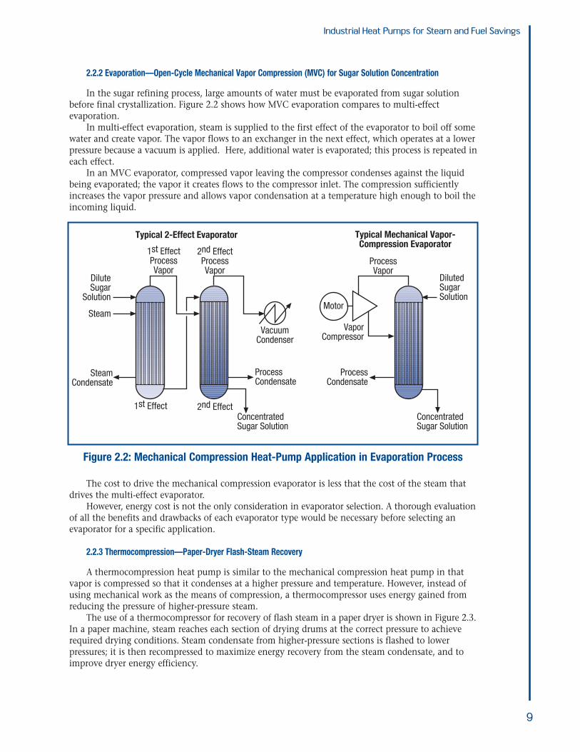
2.2.2 Evaporation—Open-Cycle Mechanical Vapor Compression (MVC) for Sugar Solution Concentration
In the sugar refining process, large amounts of water must be evaporated from sugar solutionbefore final crystallization. Figure 2.2 shows how MVC evaporation compares to multi-effect evaporation.
In multi-effect evaporation, steam is supplied to the first effect of the evaporator to boil off somewater and create vapor. The vapor flows to an exchanger in the next effect, which operates at a lowerpressure because a vacuum is applied. Here, additional water is evaporated; this process is repeated ineach effect.
In an MVC evaporator, compressed vapor leaving the compressor condenses against the liquidbeing evaporated; the vapor it creates flows to the compressor inlet. The compression sufficientlyincreases the vapor pressure and allows vapor condensation at a temperature high enough to boil the incoming liquid.
The cost to drive the mechanical compression evaporator is less that the cost of the steam thatdrives the multi-effect evaporator.
However, energy cost is not the only consideration in evaporator selection. A thorough evaluationof all the benefits and drawbacks of each evaporator type would be necessary before selecting anevaporator for a specific application.
A thermocompression heat pump is similar to the mechanical compression heat pump in thatvapor is compressed so that it condenses at a higher pressure and temperature. However, instead ofusing mechanical work as the means of compression, a thermocompressor uses energy gained fromreducing the pressure of higher-pressure steam.
The use of a thermocompressor for recovery of flash steam in a paper dryer is shown in Figure 2.3.In a paper machine, steam reaches each section of drying drums at the correct pressure to achieverequired drying conditions. Steam condensate from higher-pressure sections is flashed to lower pressures; it is then recompressed to maximize energy recovery from the steam condensate, and toimprove dryer energy efficiency.
Figure 2.2: Mechanical Compression Heat-Pump Application in Evaporation Process
• Determining if a heat pump is a potential fit with your heat-recovery application• Making an initial selection of heat-pump type• Conducting preliminary cost/benefit analysis• Performing a detailed feasibility study to define benefits and cost with sufficient confidence to
move forward with the implementation.
The information below provides assistance in working through these four steps.
3.1 When is a heat pump applicable?
Plant personnel can explore a few questions to determine if a heat pump might be applicable intheir facility:
• Where is heat available from the process? • Where is heat required in the process?• What is the value of saved energy?• Will the facility gain non-energy benefits such as environmental improvements or product
quality?
The tables that follow provide some positive and negative indicators for heat-pump applicability.These tables provide qualitative guidance on likely heat-pump feasibility. For example, if a reviewercan associate the process and site in question with more favorable features than unfavorable, then itis worth proceeding with further consideration. If unfavorable features predominate, then facilitypersonnel should re-evaluate the basis for considering a heat pump before proceeding.
10
DryerSection A
DryerSection B
High-pressureSteam
Thermocompressor
Section BCondensate
Section ACondensate
FlashDrum
Condensate Return
Figure 2.3: Thermocompression Heat-Pump Application in a Paper Dryer
Industrial Heat Pumps for Steam and Fuel Savings
11
Table 3.1 Features Favorable for Heat-Pump Installations
Features Favorable for Heat Pump Installation ReasonProcess Features
1 The process involves evaporation Opportunity for highly effective heat pump
2 There are streams in the 160 to 220° F temper- Heat in this temperature range is hot enough to not requireature range that are cooled or sent to drain too much lift to make it useful
3 Water, air or other process streams are heated Heat pumps can easily supply heat in this temperature from ambient to 150 to 250° F with steam or fuel range
4 Low-pressure steam is vented or condensed Condensing steam is a convenient heat source that a heatpump can easily use
5 The process involves distillation with a small Opportunity for highly effective heat pump because of lowtemperature range between the reboiler and heat-pump temperature liftcondenser
6 The amount of recoverable waste heat available The potential savings have to be large enough to generateexceeds about 0.5 MMBtu/h interest in a project; economies of scale favor larger
installations
7 The heat source is a clean liquid or condensing Heat capture into the heat pump is simplefluid
8 The process entails continuous operation with a Project generates more annual savingshigh number of operating hours
Energy Costs
1 Electricity is cheap relative to fuel. For example Reduces the effective cost of heat delivered by the heatthe ratio of electricity cost to fuel cost on a pumpBtu basis is < 3.
2 Both fuel and power prices are high (this is Higher energy prices increase the value of cost savingsnegative in general, but is a benefit in relative to capital cost; this improves paybackconservation efforts)
Utility System Features
1 Reducing use of heating steam, or use of fuel for Usually results in better economicsprocess heating, does not affect on-sitepower generation
Table 3.2 Features Unfavorable for Heat-Pump Installations
Features Unfavorable for Heat Pump Installation ReasonProcess Features
1 Heat is available at less than 200° F, but the A high-temperature lift requirement is not automatically aprocesses need heat at over 250° F, indicating drawback. However, high temperature lifts increase the a high-temperature lift of over 50° F effective cost of heat that a mechanical heat pump delivers,
and reduces savings. Alternately, a high-lift requirementindicates use of an absorption heat pump, which often havea higher first-cost than mechanical types.
2 Waste heat is available from cooling a small A waste-heat stream may appear useful if it is available at stream a reasonably high temperature, but if it is a low-flow stream
and cools down quickly, the heat pump will increase lift tocompensate. This leads to reduced savings
3 Additional maintenance costs Additional equipment, particularly rotating equipment, leadsto additional maintenance costs which offset the benefits
Energy Costs
1 Electricity is expensive relative to fuel. For Increases the effective cost of heat delivered by a example the ratio of electricity cost to fuel cost mechanical heat pumpon a Btu basis is > 6.
2 Both fuel and power prices are low (a benefit in Lower dollar value of energy cost savings reduces incentivegeneral, but negative for energy conservation for conservationefforts)
Utility System Features
1 Reducing use of heating steam, or use of fuel for If a heat pump affects on-site power generation, the impactheating, affects on-site power generation on power purchase must be considered, because it usually
reduces savings.
3.2 Initial selection of heat-pump type
Having established that a heat pump may be applicable, it is time to select a heat-pump type.Choosing a heat pump has a direct influence on capital and operating costs. The type of heat pumptypically employed depends on:
• The nature of the heat source (for example, liquid, gas, condensing vapor)• The nature of the heat sink (for example, liquid, gas, boiling fluid)• The required temperature lift (temperature difference between the heat input and heat
rejection temperatures).
Table 3.3 provides guidelines for selecting heat-pump type. Section 1.3 provides a description ofthe major components and equipment configuration.
The primary purpose of these guidelines is to provide a starting point for subsequent evaluationsof operating costs, savings, and capital cost. Several heat-pump types might be suitable for a givenapplication with the final choice, depending on the economic evaluations.
The vast majority of heat pumps operate with temperature lifts of less than 100° F. This briefincludes information for high-lift applications to help indicate the difference in equipment requirements needed to obtain high lifts.
3.3 Estimating Savings
For any energy savings project, the basic goal in estimating savings in operating costs is to establish the difference in costs between current and future case-base operation.
For passive-heat recovery projects, establishing this cost difference is relatively simple, becausethe value of steam or fuel saved is readily calculated.
In the case of heat pumps, the energy savings is equal to the value of steam or fuel saved, minusthe cost of operating the heat pump. The quantity of energy saved and the cost of operating the heatpump depend on the application and the heat-pump characteristics.
The example that follows illustrates the steps involved to estimate the savings that a mechanicalheat-pump application would generate.
Industrial Heat Pumps for Steam and Fuel Savings
12
Table 3.3 Guidelines for Selecting Heat-Pump Type
TemperatureLift Heat-Source Type Heat-Sink Type Suggested Heat-Pump Type
< 100° F – Sensible cooling of liquid – Sensible heating of gas or 1. Closed-cycle mechanicalliquid 2. Absorption (lithium bromide/
– Boiling liquid water)
– Partial condensation of liquid – Sensible heating of gas or 1. Closed-cycle mechanicalfrom vapor stream liquid 2. Absorption (with lithium bromide/
– Boiling liquid water working fluid)
– Condensing steam – Evaporation of water 1. Open-cycle mechanical (single-stage compressor)
2. Thermocompression
– Condensing vapor (steam – Boiling liquid 1. Semi-open-cycle mechanical or other) – Sensible heating of gas or liquid (single-stage compressor)
> 100° F – All heat sources (except steam) – All heat sinks (except steam) 1. Absorption (with high lift working fluid)2. Multistage mechanical compression
– LP steam – Higher-pressure steam header 1. Open-cycle mechanical2. Absorption (with high lift working fluid)3. Multistage mechanical compression
Industrial Heat Pumps for Steam and Fuel Savings
3.3.1 Mechanical Heat Pumps
To estimate savings for a mechanical heat pump, we need to know how much energy we willsave, along with its value. We can determine the relationships between work input, temperature lift,and heat output using a parameter known as the heat pump Co-efficient of Performance (COPHP).
COPHP is defined as: COPHP = Qout / Win
where Qout is the heat delivered by the heat pump and Win is the energy or “work” supplied to thedriver. For an ideal, Carnot-cycle heat pump, the COP is related to the heat delivery temperature andthe temperature lift:
COPHP = Tout / (Tout – Tin)
Where Tin and Tout are the temperatures, in degrees Rankine, at which the heat pump receivesand delivers heat respectively (for example, the evaporator and condenser). Note that these temperatures are not the process operating temperatures, but the heat-pump operating temperatures.Because a temperature difference between the process streams and the heat-pump working fluid mustexist, the actual temperature lift internal to the heat pump is greater than the temperature liftapplied to the process streams.
The COPHP of an actual machine will be 65 to 75% of that for an ideal machine. For the purposeof estimating heat-pump work requirements, and operating cost, it is only necessary to know theexpected operating temperatures. (Note that COPHP is not the same as the more common term,‘refrigeration COP (COPREF),’ which is defined as COPREF =Qin / Workin).
Figure 3.1 shows an example in which a process stream cooling from 170° F to 140° F is a 10 MMBtu/h heat source, and a process stream heating from 180° F to 210° F is the heat sink.
13
Heat SinkHeat Delivered by Heat Pump = Qe + W
Process StreamBeing Heated
Condenser (Heat Delivered Here)Tc
Te
Compressor
WorkW
Expansion Valve
Evaporator (Heat Accepted Here)
Waste-Heat StreamBeing Cooled
Heat SourceHeat Delivered to Heat Pump = Qe
1. Waste-heat stream evaporates heat-pump working fluid at low temperature and pressure2. Compressor increases pressure of heat-pump working fluid3. Heat-pump working fluid condenses at high temperature and pressure in the condenser, providing useful heat to a
Figure 3.1: Mechanical Heat-Pump Operating Parameters Example
210° F
170° F 140° F
tout = 230° F
tin = 120° F
Duty = 10 MMbtu/h
180° F
Qe = Heat delivered to heat pump Tin = Temperature at which heat-pump cycle accepts heatW = Work supplied to heat-pump compressor Tout = Temperature at which heat-pump cycle rejects heat
Industrial Heat Pumps for Steam and Fuel Savings
To calculate the work input, we need to determine the Tin and Tout for the heat pump. Tin is determined by the temperature approach between the heat-pump working fluid and the
lowest temperature of the heat source. In this case, the heat source is cooling to 140° F and there is a20° F approach temperature in the evaporator, so Tin = 120° F
Tout is determined by the temperature approach of the heat-pump working fluid to the hottesttemperature that the heat sink achieves. In this case, the heat source is heating to 210° F and there isa 20° F approach temperature in the condenser, so Tout = 230° F.
The ideal COPHP for this example is:
(230+460) / (230-120) = 6.3
Assuming that the actual COPHP is 70% of ideal, the estimated operating COPHP will be:
6.3 x 0.7 = 4.4
The energy balances for the heat pump are as follows:
COPHP = Qout / WinQout = Qin + W
Some mathematical rearranging gives the relationship between Qin and Win as:
Win = Qin / (COP – 1)
For the example, the work required to deliver the waste heat at the higher temperature is:
Therefore, our heat pump is going to save 12.9 MMBtu/h of heat input to the process, at the costof 862 kilowatts (kW) of electrical power.
If we assume that, in the base case, the cold process stream is heated with steam costing $5.00/MMBtu, and that power costs 4.5 cents per kilowatt-hour (kWh), then we can calculate estimated savings as:
Savings, $/h = (12.9 x 5.00) – (862 x 0.045) = 25.71 $/h
If the process runs 8,500 hours per year, the project could be justified based on obtaining$218,500/yr in annual savings.
Note that if the driver were not an electric motor, the cost of shaft work for the particular deviceused would be substituted for power cost. In instances where turbines, or combustion engines aredrivers, considering the overall site energy balance is necessary to correctly determine the cost ofwork.
The method described above helps determine if there are sufficient savings and incentive to pursue a heat-pump application. Although simplified, this method gives a reasonable idea of theenergy-cost economics of installing a mechanical heat pump.
When evaluating economics, also consider non-energy cost benefits:
• Product quality: In lumber-drying applications, the gentler heating resulting from use of heat pumps results in better quality dried lumber and higher yields.
• Offset capital costs: In evaporation applications, using a heat pump means that boiler steam load and cooling water duty are avoided. This leads to reduced capital for boilers and/orcooling towers, together with lower NOx emissions.
14
Industrial Heat Pumps for Steam and Fuel Savings
In addition, other costs may exist:
• Operating costs for auxiliary pumps and fans associated with the heat pumps• Maintenance costs for the heat-pump equipment.
In conclusion, try to include all relevant costs and benefits in the detailed economic calculations.
3.3.2 Other Heat Pump Types
The COPHP estimation method described above will work for most types of mechanically drivenheat pumps.
For thermocompression heat pumps, the relationships between the heat recovered, thermal energyinput, and temperature lift can be determined from specific charts provided by thermocompressormanufacturers.
3.4 What will the capital cost be?
Cost estimates are available for only a few common heat-pump applications:
• Lumber-drying kilns• Mechanical-compression evaporators• Thermocompression evaporators• Steam jets for paper machines.
Most other industrial heat pump installations are custom designed, and must be costed by sizingthe individual components (heat exchangers, compressors, etc.).
Consequently, there is a great deal of variation in costs. Historical costs for closed-cycle mechanical heat-pump systems range from $50,000 to over $200,000 per MMBtu of heat delivered;no predictable relationship exists between size of unit and cost.
As indicated earlier, simple paybacks for industrial heat-pump applications, where the primarygoal is energy-cost reductions are typically 2 to 5 years.
3.5 What is the path from basic concept to installation for a heat-pump project?
As with any heat-recovery project, once a heat-pump opportunity is identified, the project needsto undergo a feasibility study and a detailed engineering design.
However, a few areas warrant special attention:
• Sizing: It is better to have a small, base-loaded installation with high operating hours than a unit that works at part load, part time.
• Back-up: A process operation must still be able to run should the heat pump break down. Address the need for a back-up.
• Alternates: A heat-pump installation will usually be more expensive than a passive-heat recovery project because heat has to be transferred twice (in and out of the heat pump), and a piece of rotating equipment may be needed.
A thorough heat-pump evaluation includes confirmation that a better alternative project has not been overlooked.
Use of heat-integration methods, such as Pinch Technology, are useful for this type of evaluation. Pinch Technology, in particular, provides a set of systematic analytical methods and tools that help identify both heat-recovery project opportunities and heat-pumping opportunities.
15
A BestPracticesSteamTechnicalBrief
IndustrialHeat Pumpsfor Steamand FuelSavings
U.S. Department of EnergyEnergy Efficiency and Renewable EnergyBringing you a prosperous future where energy is clean, abundant, reliable, and affordable
Energy efficiency and clean, renewable energy will mean a stronger economy, a cleaner environment, and greater energyindependence for America. By investing in technology breakthroughs today, our nation can look forward to a more resilient economy and secure future.
Far-reaching technology changes will be essential to America’senergy future. Working with a wide array of state, community,industry, and university partners, the U.S. Department of Energy’sOffice of Energy Efficiency and Renewable Energy invests in adiverse portfolio of energy technologies that will:
• Conserve energy in the residential, commercial, industrial, government, and transportation sectors
• Increase and diversify energy supply, with a focus on renewable domestic sources
• Upgrade our national energy infrastructure• Facilitate the emergence of hydrogen technologies
as a vital new “energy carrier.”
The Opportunities
Biomass ProgramUsing domestic, plant-derived resources to meet our fuel, power,and chemical needs
Building Technologies ProgramHomes, schools, and businesses that use less energy, cost less tooperate, and ultimately, generate as much power as they use
Distributed Energy & Electric Reliability ProgramA more reliable energy infrastructure and reduced need for newpower plants
Federal Energy Management ProgramLeading by example, saving energy and taxpayer dollars in federalfacilities
FreedomCAR & Vehicle Technologies ProgramLess dependence on foreign oil, and eventual transition to an emisions-free, petroleum-free vehicle
Geothermal Technologies ProgramTapping the earth’s energy to meet our heat and power needs
Hydrogen, Fuel Cells & Infrastructure Technologies ProgramPaving the way toward a hydrogen economy and net-zero carbonenergy future
Industrial Technologies ProgramBoosting the productivity and competitiveness of U.S. industrythrough improvements in energy and environmental performance
Solar Energy Technology ProgramUtilizing the sun’s natural energy to generate electricity and providewater and space heating
Weatherization & Intergovernmental ProgramAccelerating the use of today’s best energy-efficient and renewabletechnologies in homes, communities, and businesses
DOE Information ClearinghousePhone: (800) 862-2086Fax: (360) [email protected]
Visit our home page atwww.oit.doe.gov
Please send any comments,questions, or suggestions [email protected]
Industrial Technologies ProgramEnergy Efficiency and Renewable EnergyU.S. Department of EnergyWashington, DC 20585-0121
Industrial Technologies Program
DOE/GO-102003-1735June 2003
Boosting the productivity and competitiveness of U.S. industry through improvements in energy and environmental performanceA STRONG ENERGY PORTFOLIO FOR A STRONG AMERICA
ACKNOWLEDGEMENTS:
The Industrial Technologies Programwould like to thank Andrew McMullan,Veritech Inc., for writing this BestPracticesSteam Technical Brief, and theBestPractices Steam technical subcommittee for reviewing thepublication.