5
Inferno Stringing Machine Manual Installation and Operation

Inferno Stringing Machine Manual
Installation and Operation
- 1 -
Table of Contents 1 TABLE OF CONTENTS.........................................................................1 2 DESCRIPTION OF PARTS....................................................................1 3 FRAME MOUNTING AND TENSIONING THE STRING.......................2 4 STRINGING THE FRAME .....................................................................2 5 BASE CLAMP ADJUSTMENT…………………………….......................3 6 PREPARATION OF STRINGING...........................................................3 7 CALIBRATING THE MACHINE……......................................................4
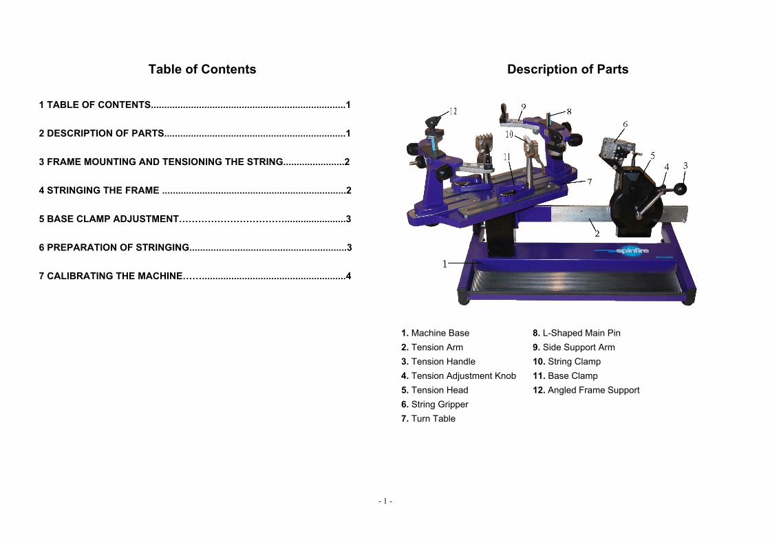
Description of Parts
1. Machine Base 8. L-Shaped Main Pin 2. Tension Arm 9. Side Support Arm 3. Tension Handle 10. String Clamp 4. Tension Adjustment Knob 11. Base Clamp 5. Tension Head 12. Angled Frame Support6. String Gripper 7. Turn Table

- 2 -
Frame mounting and tensioning the string
Stringing the frame
Step 1: To set the tension, turn the knob until registered at the desired poundage. For example, to set the tension for 23 pounds, the tension scale should read 21 pounds and the collar should read 2 pounds. The number should line up with the outside edge of the marker. We recommend that you return the tension to 9 pounds when not using the machine.
Step 2: To pull the string place it in the string gripper (6). Hold string to a 90 degree angle as shown (or use your finger to push back the gripper) until it grips the string securely.
Step 3: Rotate the tension handle (3) to move the tension head away from the turn table (7).
Step 1: Insert the angled frame supports (12) into the appropriate slots located on the end of the side support arms (9). The two slots are designed to accommodate most racquets.
Step 2: Place the racquet on the machine. The 12 and 6 o’clock frame supports (12) should be on the inside of the frame. The angled frame supports (12) should be on the outside. Tighten the 12 and 6 o’clock frame supports (12) until they are just touching the frame. Then tighten the angled frame supports (12) until they are firm (finger tight). Go back to the 12 and 6 o’clock frame supports (12) and tighten them to finger tight also. The fit should be snug, but use caution. NOTE: Over-tightening can cause stress on the frame.

- 3 -
Base Clamp adjustment
Preparation of Stringing
This only needs to be done if your base clamps (11) are getting loose. Locate the black cap on the backside of the base clamp (11). Carefully pull it off.
Turn the base clamp (11) so that the outer port is aligned with the inner port. Take the 3mm Allen Key and insert it into the internal adjustment screw. Turn clockwise to increase tension. The ideal locking position for the lever should be down the center of the base clamp (11).
To clamp the string, squeeze the lever closed (do not close the lever further than the image shown below (left)). To release the string, pull the lever out.
To tighten the string clamp (10), turn the dial clockwise. To loosen it, turn the dial counter-clockwise. NOTE: Before stringing a racquet, the tension on the string clamp (10) has to be adjusted in accordance with the type of string gauge being used. If the string is of a thin gauge (eg, 16L, 17 or 18) then the string clamp (10) may need to be tightened. If the string gauge is thick (eg, 15, 15L or 16) then the string clamp (10) may need to be loosened.
Step 4: Keep rotating until the tensioning lever clicks out. This locks the tension head to the tension arm. Your string should be at the specified tension now.

- 4 -
Calibrating the Machine Calibrate the tension head when you find the stringing machine is not pulling at the correct tension. To test your machine you need a Tension Calibration Scale. It is recommended to wear safety glasses during the calibration.
Locking Lever
Safety Screw
Tension Calibrator
Tension Adjustment Screw
GripperString Gripper Adjustment Screw
Wrench
Brake Screw
Fastness Screw
Head Cover
Step 1: Set the tension head to 60 pounds. Use the string clamp (10) to secure the string on one end of tension calibration scale and place the string that is attached to the other end of tension calibration scale into the string gripper (6). Rotate the crank of the tension head clockwise until the tension locking lever pops out. Step 2: Check whether the tension indicated by the tension calibration scale is the same as the tension setting of the tension head. Repeat the process four or five times to have the correct tension indication on the tension calibration scale and avoid a poor calibration job due to string stretching. If the tension indicated by the calibrator does not match the tension setting of the tension head, you will need to adjust the catch on the tension head. Release the tension head and remove the string out of the string gripper.
Step 3: Use a 2mm Allen key to loosen the safety screw. To achieve a higher tension, turn the tension adjustment screw counter-clockwise by using a 2.5mm Allen key. To reduce the tension, turn it clockwise. For instance, if the tension locking lever releases before 60 pounds, turn the tension adjustment screw counterclockwise to adjust the catch downward. Step 4: After the catch has been adjusted, be sure to tighten the safety screw. Step 5: After stringing for a long time, it may be necessary to adjust the tension locking lever of the tension head. Insert the 6mm Allen wrench into the socket screw through the hole in the cover, use the 10mm wrench to hold the hexagon head screw on the opposite of the tension head. Turn both the 6mm Allen wrench and the 10mm wrench in the same direction simultaneously until the locking lever returns to its original setting.
Step 6: Downward calibration adjustments will move the locking lever further from the catch. Upward calibration adjustments will move the locking lever closer to the catch. The proper distance between the catch and the locking lever is approximately 20-25mm. After the proper distance is achieved, hold the 6mm Allen wrench still and tighten the hexagon head screw by turning the 10mm wrench clockwise. Do not apply excessive force or over-tighten the screw, this could make the tension head hard to crank.


