Vol. 1, No. 7: May-June, 1988 Special Design Project Issue I nflatable Space Structures I nflatable space structures include single and multiwalled bladders made of pliable compo- site materials. Such construction offers an attrac- tive alternative to more conventional rigid metal systems for certain specialized uses. A key ad- vantage is the ability to transport large habitats and other structures for use in low-Earth orbit and on planetary surfaces in a compact, launch- efficient, easy to deploy form. Realization of this benefit will require further development and demonstration of new material technologies. Some new materials show real promise but will re- quire additional testing to ensure long-term safety and reliability under harsh environmental condi- tions posed by space applications. Space habitats must provide means to contain i nternal gases and maintain constant purity and atmospheric pressure to sustain life. Pressure ves- sel walls must afford a reasonable degree of re- sistance to micrometeorites, space debris and radiation, yet must be as light and compact as possible to maximize launch efficiency. Exterior surfaces must be able to withstand long-duration exposure to molecular oxygen, ultraviolet rays and temperature extremes. Interior surfaces must be nonflammable and must not offgas toxic or noxious materials. Recent advancements in nonmetallic material technology warrant optimism that these require- ments can be accommodated. SICSA staff and Experimental Architecture graduate students have undertaken conceptual studies which have explored uses of composite nonmetallic inflata- ble structures for advanced space missions. LIH Spacehab Concept Representative Applications Large habitable environments in low-Earth orbit and on planetary surfaces. Supplemental storage and waste con- tainment for the Space Station. Airlocks and connecting tunnels for orbit- i ng and planetary surface facilities. Means to deploy antennas and other me- chanically-rigidized structures. A Publication of the University of Houston's College of Architecture
I nflatable space structures include single andmultiwalled bladders made of pliable compo-site materials. Such construction offers an attrac-tive alternative to more conventional rigid metalsystems for certain specialized uses. A key ad-vantage is the ability to transport large habitatsand other structures for use in low-Earth orbit andon planetary surfaces in a compact, launch-efficient, easy to deploy form. Realization of thisbenefit will require further development anddemonstration of new material technologies.Some new materials show real promise but will re-quire additional testing to ensure long-term safetyand reliability under harsh environmental condi-tions posed by space applications.
Space habitats must provide means to containinternal gases and maintain constant purity andatmospheric pressure to sustain life. Pressure ves-sel walls must afford a reasonable degree of re-sistance to micrometeorites, space debris andradiation, yet must be as light and compact aspossible to maximize launch efficiency. Exteriorsurfaces must be able to withstand long-durationexposure to molecular oxygen, ultraviolet raysand temperature extremes. Interior surfaces mustbe nonflammable and must not offgas toxic ornoxious materials.
Recent advancements in nonmetallic materialtechnology warrant optimism that these require-ments can be accommodated. SICSA staff andExperimental Architecture graduate studentshave undertaken conceptual studies which haveexplored uses of composite nonmetallic inflata-ble structures for advanced space missions.
LIH Spacehab Concept
Representative Applications
Large habitable environments in low-Earthorbit and on planetary surfaces.
Supplemental storage and waste con-tainment for the Space Station.
Airlocks and connecting tunnels for orbit-i ng and planetary surface facilities.
Means to deploy antennas and other me-chanically-rigidized structures.
A Publication of the University of Houston's College of Architecture
Background
Many innovative inflatable space structure con-
cepts have been proposed during the last three
decades. A few have resulted in full-size mock-
ups and working prototypes. The Goodyear Aer-
ospace Corporation (GAC), now part of the Lor-
al Systems Group, has been responsible for thedetailed design and fabrication of the majority of
these systems. Unfortunately, GAC has discontin-
ued this activity due to diminished government
sponsor interest and funding. 24 Foot Diameter Toroidal Structure
GAC designed and developed three pressur-
i zed module prototypes under contract with the
NASA Langley Research Center. The largest was
a 24 foot outside diameter toroidal space habi-
tat structure created in 1960 to demonstrate infla-
tion, repackability, gas retention, thermal perfor-
mance and structural characteristics. In 1965
GAC developed a lunar shelter to support twopeople for periods of 8-30 days with necessary
radiative thermal control and micrometeorite
protection. A 12.8 foot diameter, 37.5 foot long
"Moby Dick" structure was developed in 1968 as
a prototype for a 110 foot long space habitat.
GAC also fabricated two expandable crew
transfer tunnels for space. The first (12 feet long),
designed in 1966 by the Air Force Propulsion La-
boratory, was developed to connect a Gemini
capsule to Skylab's Manned Orbital Laboratory(MOL) crew quarters. The second, in 1979, pro-
duced a 14.2 foot long flexible section of a tunnel
between the Orbiter's crew cabin and the
Spacelab module under contract with the
McDonnell Douglas Services Company for the
NASA Marshall Space Flight Center.
I nflatable airlock technologies have been dem-
onstrated by the U.S. and Soviet Union. A 5.2 foot
diameter, 6.2 foot long airlock developed
through a joint NASA-Department of Defense
venture and constructed by GAC in 1967 was de-
signed to be mounted on a Skylab-type vehicle.
The U.S.S.R. demonstrated an inflatable airlock
on its Vostok 2 spacecraft in March, 1985. A mis-
calculation in the pressurized size of a cosmon-
aut's EVA suit nearly resulted in tragedy when heexperienced great difficulty reentering through
the airlock's small hatch.
Construction: meriodonally-wound Dacron filaments with a Bu-tyl rubber binder and internal bladder of Butyl-impregnated ny-l on for gas retention packaged in an 8 foot diameter hub forl aunch with deployed volume 2,300 cubic feet. Weight approx-i mately 4 oz./ftz of surface area. Designed for 5 psi pressure.
7 Foot Diameter, 15 Foot Long Lunar Shelter
Construction: 3-layer laminate consisting of nylon outer cover,closed-cell vinyl foam, and inner nylon cloth bonded by polyes-ter adhesive layers. Internal volumes of shelter and airlockwere 410 cubic feet and 105 cubic feet, respectively. Weight126 pounds/fl-2(total, 326 pounds). Designed for 5 psi pressure.
12.8 Foot Diameter, 37.5 Foot Long "Moby Dick"
Construction: 1/6 inch thick gas bladder made from 2 inch wideDacron 52 yam dipped in a polyester resin bath. The bladderwas sealed by a polyvinyl chloride (PVC) foam and the entirestructure was covered by a 1-3/4 inch flexible polyurethanefoam, over which was pkiced a nylon film-fabric laminate paint-ed with a thermal control coating. The 1,622 pound structurewas designed for 5 psi pressure.
Illustrations on this page by LI Hua based upon GAC data.
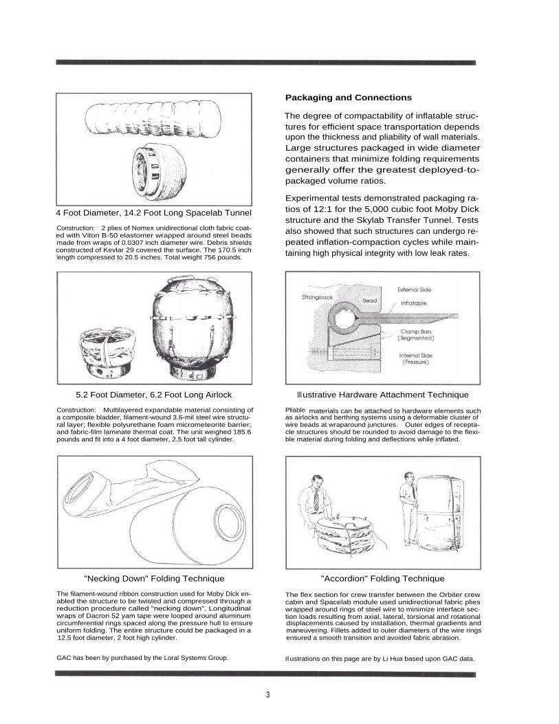
Construction: 2 plies of Nomex unidirectional cloth fabric coat-ed with Viton B-50 elastomer wrapped around steel beadsmade from wraps of 0.0307 inch diameter wire. Debris shieldsconstructed of Kevlar 29 covered the surface. The 170.5 inchlength compressed to 20.5 inches. Total weight 756 pounds.
Packaging and Connections
The degree of compactability of inflatable struc-tures for efficient space transportation dependsupon the thickness and pliability of wall materials.Large structures packaged in wide diametercontainers that minimize folding requirementsgenerally offer the greatest deployed-to-packaged volume ratios.
Experimental tests demonstrated packaging ra-tios of 12:1 for the 5,000 cubic foot Moby Dickstructure and the Skylab Transfer Tunnel. Testsalso showed that such structures can undergo re-peated inflation-compaction cycles while main-taining high physical integrity with low leak rates.
Construction: Multilayered expandable material consisting ofa composite bladder, filament-wound 3.6-mil steel wire structu-ral layer; flexible polyurethane foam micrometeorite barrier;and fabric-film laminate thermal coat. The unit weighed 185.6pounds and fit into a 4 foot diameter, 2.5 foot tall cylinder.
Pliable materials can be attached to hardware elements suchas airlocks and berthing systems using a deformable cluster ofwire beads at wraparound junctures. Outer edges of recepta-cle structures should be rounded to avoid damage to the flexi-ble material during folding and deflections while inflated.
The filament-wound ribbon construction used for Moby Dick en-abled the structure to be twisted and compressed through areduction procedure called "necking down". Longitudinalwraps of Dacron 52 yam tape were looped around aluminumcircumferential rings spaced along the pressure hull to ensureuniform folding. The entire structure could be packaged in a12.5 foot diameter, 2 foot high cylinder.
The flex section for crew transfer between the Orbiter crewcabin and Spacelab module used unidirectional fabric plieswrapped around rings of steel wire to minimize interface sec-tion loads resulting from axial, lateral, torsional and rotationaldisplacements caused by installation, thermal gradients andmaneuvering. Fillets added to outer diameters of the wire ringsensured a smooth transition and avoided fabric abrasion.
GAC has been by purchased by the Loral Systems Group. Ill ustrations on this page are by Li Hua based upon GAC data.
3
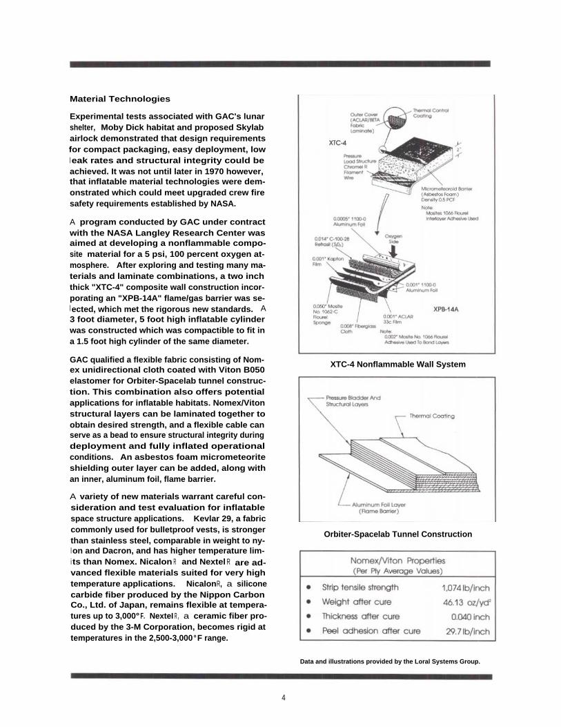
Material Technologies
Experimental tests associated with GAC's lunarshelter, Moby Dick habitat and proposed Skylabairlock demonstrated that design requirementsfor compact packaging, easy deployment, lowl eak rates and structural integrity could beachieved. It was not until later in 1970 however,that inflatable material technologies were dem-onstrated which could meet upgraded crew firesafety requirements established by NASA.
A program conducted by GAC under contractwith the NASA Langley Research Center wasaimed at developing a nonflammable compo-site material for a 5 psi, 100 percent oxygen at-mosphere. After exploring and testing many ma-terials and laminate combinations, a two inchthick "XTC-4" composite wall construction incor-porating an "XPB-14A" flame/gas barrier was se-l ected, which met the rigorous new standards. A3 foot diameter, 5 foot high inflatable cylinderwas constructed which was compactible to fit ina 1.5 foot high cylinder of the same diameter.
GAC qualified a flexible fabric consisting of Nom-ex unidirectional cloth coated with Viton B050elastomer for Orbiter-Spacelab tunnel construc-tion. This combination also offers potentialapplications for inflatable habitats. Nomex/Vitonstructural layers can be laminated together toobtain desired strength, and a flexible cable canserve as a bead to ensure structural integrity duringdeployment and fully inflated operationalconditions. An asbestos foam micrometeoriteshielding outer layer can be added, along withan inner, aluminum foil, flame barrier.
A variety of new materials warrant careful con-sideration and test evaluation for inflatablespace structure applications. Kevlar 29, a fabriccommonly used for bulletproof vests, is strongerthan stainless steel, comparable in weight to ny-l on and Dacron, and has higher temperature lim-i ts than Nomex. Nicalon R and Nextel R are ad-vanced flexible materials suited for very hightemperature applications. NicalonR, a siliconecarbide fiber produced by the Nippon CarbonCo., Ltd. of Japan, remains flexible at tempera-tures up to 3,000°F. NexteI R , a ceramic fiber pro-duced by the 3-M Corporation, becomes rigid attemperatures in the 2,500-3,000°F range.
XTC-4 Nonflammable Wall System
Orbiter-Spacelab Tunnel Construction
Data and illustrations provided by the Loral Systems Group.
4
Example Foam-Rigidized Wall System
Foam-Rigidized Structures
I t may be necessary in some inflatable space
structure applications to provide means to rigi-
dize the systems so that overall forms are re-
tained after inflation gases are gone. Examples
are hangars and other storage facilities that
open directly to the space environment, and stiffelements such as beams and trusses which must
be designed to retain structural integrity following
micrometeorite penetrations.
Rigidization can be accomplished by predistribu-
tion of inactivated foams on deployable surfac-
es. This approach involves incorporating a flexi-
ble mesh core material impregnated with a gela-
tin resin between membranes of a sealed struc-ture during the fabrication process. The system
remains pliable during the packaged configura-
tion. When the structure is deployed and the wall
cavity is vented to vacuum, the gelatin-resin
moisture escapes causing foam to expand and
harden the mesh core. GAC investigated twelvechemical systems for this process and selected a
reversible-type gelatin with a Scott foam mesh
core as the most promising material combination.
The outer cover in this example is a film cloth laminate basecloth is Stern and Stern A4787 nylon at 0.84 oz./square yard;fil m is Capron type 77C 1-mil at 0.42 oz/square yard. Mechanically-Rigidized Structures
Deployment of a Wire Structure
Rigidization through overpressure/yielding of a
wire matrix has proven very effective for deploy-
ment of such thin skinned space structures as bal-l oons, antennas and reflectors. An inflated pres-
sure bladder is typically used to stress a wire net
surface material beyond its yield point through
controlled overpressurization. The surface mate-rial then retains its shape after pressurization is lost.
GAC has demonstrated a variety of mechanical-l y-rigidized system applications, A 30 foot wire-grid satellite reflector had a photolyzable film
bladder that photodegraded and evaporated
under the influence of space vacuum and tem-
peratures. An aluminum wire-grid torus was de-
ployed as a planar space target. A 10 foot long,
30 inch high fan beam deployable antenna usedoverpressurized wire tubes. GAC aslo created a
14 foot diameter balloon of .25-mil aluminizedMylar and 5-mil aluminum wire to serve as a loca-
tion marker on the lunar surface.
Data and illustrations provided by the Loral Systems Group.
5
A.
Simple Tubes/Bladders B. Tubular Frame Structures
C. Cocoon/Ribbed Structures D. Foam-Rigidized Tubes/Bladders
Types of Forms
Inflatable and inflation-deployed structures canbe formed in a wide variety of shapes and sizesto meet specific application requirements. Largestructures most advantageously exploit the inher-ent benefit of this technology They potentiallyafford means to put expansive systems into op-eration in a very launch volume, time and labor-efficient manner. Spacious, potentially habitablevolumes can be created which far exceed sizeconstraints placed upon conventional modulesby launch system payload dimensions. Accu-rate curve profiles for very large antennas andreflectors can be readily achieved.
E. Mechanically-Rigidized Structures
Concepts/illustrations prepared by Larry Bell and Li Hua for wyle Laboratories in support of a NASA-sponsored inflatable structures study.
6
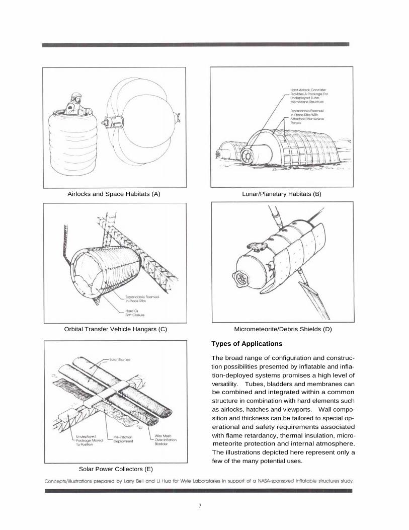
Airlocks and Space Habitats (A) Lunar/Planetary Habitats (B)
Orbital Transfer Vehicle Hangars (C) Micrometeorite/Debris Shields (D)
Solar Power Collectors (E)
Types of Applications
The broad range of configuration and construc-tion possibilities presented by inflatable and infla-tion-deployed systems promises a high level ofversatility. Tubes, bladders and membranes canbe combined and integrated within a commonstructure in combination with hard elements suchas airlocks, hatches and viewports. Wall compo-sition and thickness can be tailored to special op-erational and safety requirements associatedwith flame retardancy, thermal insulation, micro-meteorite protection and internal atmosphere.The illustrations depicted here represent only afew of the many potential uses.
7
I nflatable Space Station Concept Typical Pod in Packaged and Deployed Stages
Spacehab Project
SICSA's predecessor organization, the Environ-mental Center, investigated ways to constructlarge (50 persons or more) space habitats undercontract with the NASA-Johnson Space Center inthe early 1980s. One concept proposed that in-flatable 68 foot diameter composite "pods" besealed around fully integrated utility cores andairlock systems. These pod units would be inter-connected by an infrastructure of conventionalaluminum modules (not shown).
Spacehab's pods were proposed to be con-structed of a net of one inch diameter Kevlarcables spaced 14-16 inches on center that areset between inner and outer layers of Kevlar.Loose layers of thin film Mylar insulation would sur-round the net to fill grid voids. A single layer ofKevlar (10 oz./yd 2) would serve as a micromete-orite barrier outside the pressure hull and wouldbe covered by a 4-mil film of Tedlar (polyvinylflouride for ultraviolet and molecular oxygen pro-tection. Kevlar layers totaling 20 oz./yd 2 wouldform the pressure hull. The inner surface would besilicone-coped in a 40-mil thick matrix to preventoffgassing and offer fire resistance.
Reinforcement Cables and Composite SkinEstimated Weight - 16,000 pounds
Experimental Architecture concepts for Soacehab by Muhnmmad Siddinui. Frnesto L icen Shirish P a te ' and Sandi Susant~
8
View of Exercise - Recreation Pod Sector
View of Galley - Wardroom Pod Sector
General View of "Upper" Level General View of "Lower" Level
This inflatable structure is proposed for use at amature stage of lunar base development whenmining and industrial production warrant accom-modations for relatively large crews. Designgoals are to minimize launch weight and erectionti me. The 70 foot diameter habitat would becomprised of prefabricated aluminum trussesand columns enclosed within a flexible compo-site pressure bladder similar to Spacehab. Theseelements would be delivered in a payload carri-er containing hatches which separate to pro-vide two independent entry/egress airlocks.
The spherical pressure vessel would be setabove a hemispherical surface depression af-forded by an existing crater and/or shaped det-onation charge. This is important in order to avoidthe need for powerful means to anchor the struc-ture in a manner to deform the bladder from anatural circular cross section and resist high infla-tion lifting forces. The upper hemisphere of thevessel might be covered with a few meters of lu-nar soil (regolith) to provide a radiation barrier.
Partial Interior Plan Inside Bladder
Lunarhab construction concept and models by Warren China,
1 0
Stage One: Prepare the construction site and offload the
Stage Two:
Position and connect the main transverse trusses;habitat structure payload carrier.
then inflate and complete the framework.
Stage Three:
Attach floor panels and utility interfaces; then
Stage Four:
Install the interior partitions, crew system and la-install the life support systems,
boratory facilities.
1 1
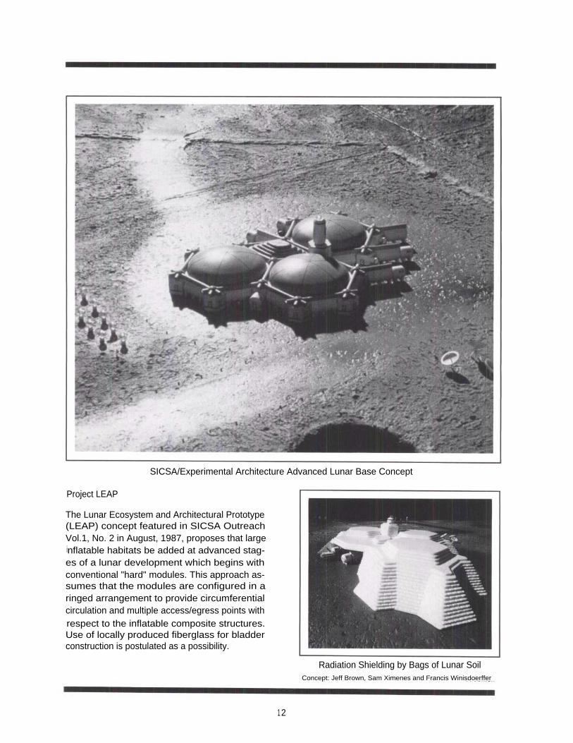
SICSA/Experimental Architecture Advanced Lunar Base Concept
Project LEAP
The Lunar Ecosystem and Architectural Prototype(LEAP) concept featured in SICSA OutreachVol.1, No. 2 in August, 1987, proposes that largeinflatable habitats be added at advanced stag-es of a lunar development which begins withconventional "hard" modules. This approach as-sumes that the modules are configured in aringed arrangement to provide circumferentialcirculation and multiple access/egress points withrespect to the inflatable composite structures.Use of locally produced fiberglass for bladderconstruction is postulated as a possibility.
Radiation Shielding by Bags of Lunar SoilConcept: Jeff Brown, Sam Ximenes and Francis Winisdoerffer
12
Longitudinal Section Through an Initial Stage Inflatable Facility
Longitudinal Section Through an Advanced Stage Inflatable Facility
Plan Configuration Concept
Lunar Agriculture Facility
I nflatable structures can offer large plant growthenvironments to provide food and oxygen for lu-nar and planetary applications. System ele-ments can include a growth chamber with insulat-i ng foam-rigidized ribs; a processor to reclaim nu-trients from inedible biomass; a module where al-gae is grown to produce oxygen; and a modulecontaining all necessary support and control sys-tems. Initial installations might be set directly uponlunar soil and anchored by screw augers. Ad-vanced facilities might incorporate floor slabsmade of lunar-derived concrete.
SICSA concepts proposed by Thomas Polette and Larry Toups.
1 3
Section Through Trash Management System and Resource Module
Space Station Trash Management
Each Space Station crew mission rotation cyclecan be expected to generate hundreds of cu-bic feet of dry trash which must be stowed until itcan be returned to Earth or otherwise disposed ofi n a safe, clean manner. Expendable bags at-tached to an external receiving/shredding sys-tem offer a promising volume-efficient solution.
This SICSA/Experimental Architecture conceptproposes that a receiving chamber with a shred-der be attached to a Space Station berthingport. Expendable bags are sealed into the out-ermost end of the chamber by inflatable collarsthat press against a metal outer rim. The 10 footdiameter, 4 foot-3 inch deep bag packages
produce a 15 foot diameter, 1,767 cubic footspherical trash holding area when deployed.
After trash is manually inserted into a 4 cubic footairlock in the chamber, the material is automati-cally forced through cutting blades into the at-tached bag. Vents in the bag allow trappedgases to escape.
View Showing Bag Package Attached
SICSA trash management concept by Rodney Gentry.
14
Section Through Receiving Chamber
Detail "A" Showing Bag Attachment Seal
View Showing Inflated Bag Attached
Computer generated SICSA drawings prepared by Rodney Gentry.
1 5
SICSA Background
SICSA is a nonprofit research, design and education-al entity of the University of Houston College of Archi-tecture. The organization's purpose is to undertakeprograms which promote international responses tospace exploration and development opportunities.I mportant goals are to advance peaceful and be-neficial uses of space and space technology and toprepare professional designers for challengesposed by these developments. SICSA also works toexplore ways to transfer space technology for Earthapplications.
SICSA provides teaching, technical and financialsupport to the Experimental Architecture graduateprogram within the College of Architecture. The pro-gram emphasizes research and design studies di-rected to habitats where severe environmental con-ditions and/or critical limitations upon labor, materialsand capital resources pose special problems. Grad-uate students pursue studies which lead to a Masterof Architecture degree.
SICSA Outreach highlights key space develop-ments and programs involving our organization, ournation, our planet and our Solar System. The publica-tion is provided free of charge as a public service toreaders throughout the world. Inquires about SICSAand Experimental Architecture programs, or articles inthis or other issues of SICSA Outreach, should be sentto Professor Larry Bell, Director.
SICSA Lunarhab Concept
I nflatable composite structures potentially offer ameans to create large, environmentally-controlled space facilities which can be pack-aged in a compact form for launch and easilydeployed in a time and labor-efficient manner.SICSA staff and graduate students in the UH Ex-perimental Architecture program have undertak-en a variety of studies to determine applications,conditions and design concepts which can opti-mize these benefits.
This issue of SICSA Outreach highlights some se-l ected inflatable space structure precedentsand possibilities to create low-Earth orbit, lunarand planetary facilities.