Page 1
Influence of Chirality on the Electromagnetic Wave Propagation: Unbounded Media And Chirowaveguides
Priyá Dilipa Gaunço Dessai
Dissertation submitted to obtain the Master Degree in
Electrical and Computer Engineering
Jury
President: Professor José Manuel Bioucas Dias Supervisor: Professor Carlos Manuel dos Reis Paiva Co- Supervisor: Professor António Luís da Silva Topa Member Professor Sérgio de Almeida Matos
December 2011
Page 2
Abstract
When a chiral medium interacts with the polarization state of an electromag-
netic plane wave and couples selectively with either the left or right circularly
polarized component, we call this property the optical activity.
Since the beginning of the 19th century, the study of complex materials has
intensi�ed, and the chiral and bi-isotropic (BI) media have generated one of
the most interesting and challenging subjects in the electromagnetic research
groups in terms of theoretical problems and potential applications.
This dissertation addresses the theoretical interaction between waves and the
chiral media.
From the study of chiral structures it is possible to observe the e�ect of the
polarization rotation, the propagation modes and the cuto� frequencies. The
re�ection and transmission coe�cients between a simple isotropic media (SIM)
and chiral media are also analyzed, as well as the relation between the Brewster
angle and the chiral parameter.
The BI planar structures are also analyzed for a closed guide, the parallel-plate
chirowaveguide, and for a semi-closed guide, the grounded chiroslab. From these
structures we can investigate the surface modes as a function of chirality, which
will lead us to understand the physical aspects of the chirowaveguides.
Keywords: Chiral media; optical activity; polarization; chirowavguides;
bi-isotropic planar structures; re�ection and transmission; Brewster
angle
i
Page 3
Resumo
Desde o início do século XIX que o estudo de materiais complexos tem aumen-
tado, sendo que os meios bi-isotrópicos e quirais geraram temas de estudos muito
interessantes e desa�antes dentro das comunidades cientí�cas quanto à resolução
de problemas teóricos, bem como ao estudo das suas aplicações práticas.
Uma onda electromagética plana ao passar por um meio quiral, vai provocar
uma rotação de polarização sobre o plano. A onda adquire uma rotação circular
esquerda e uma circular direita, a este fenómeno dá-se o nome de actividade
óptica.
Esta dissertação tem como objectivo analisar propriedades dos meios quirais,
como o efeito da rotação de polarização, modos de propagação e frequências de
corte. Também é abordado o estudo de transmissão e re�exão numa interface
dieléctrica-quiral, onde se determinam coe�cientes de transmissão e re�exão e é
referida a relação entre o ângulo de Brewster e o parâmetro quiral.
A propagação guiada em meios quirais é abordada através do estudo de es-
truturas bi-isotrópicas planares, como é o caso de um guia fechado (um plano
assente sobre placas condutoras), e o caso de um guia semi-aberto (um guia
quiral assente sobre um plano condutor e em contacto com o ar).
Palavra chave: Meio quiral; actividade óptica, polarização, guias de
onda quirais, estruturas biisotrópicas planas, re�exão e transmissão;
ângulo de Brewster
ii
Page 4
AKNOWLEDGEMENTS
I would like to express my gratitude to my supervisor Professor Carlos Paiva
for suggesting me this dissertation, for his guidance and valuable critics and
suggestions.
I also would like to thank to professor António Topa for his availability and
precious advices.
To Filipa Prudêncio i would like to thank for being so patience and helpful.
I want to make a special reference to José Pedro Salreta, Abel Camelo, Pedro
Rodrigues, David Sousa and last but not least, Tiago Moura. You have all
supported me along my journey at IST and your friendship, fellowship and
company are truly remarkable.
Finally, i want to thank all my family, specially my father, mother, sister and
Freddy for their patience and a�ection.
iii
Page 5
Contents
Abstract i
keywords i
Resumo ii
Palavra chave ii
Sumario ii
Acknowledgements iii
List of Symbols xii
1 Introduction 1
1.1 State of the art . . . . . . . . . . . . . . . . . . . . . . . . . . . . 2
1.2 Motivation and Objectives . . . . . . . . . . . . . . . . . . . . . . 5
1.3 Structure of the dissertation . . . . . . . . . . . . . . . . . . . . . 7
1.4 Main contributions . . . . . . . . . . . . . . . . . . . . . . . . . . 8
2 Bi-isotropic and chiral media properties 11
iv
Page 6
2.1 Introduction . . . . . . . . . . . . . . . . . . . . . . . . . . . . . . 12
2.2 Chiral Media . . . . . . . . . . . . . . . . . . . . . . . . . . . . . 13
2.2.1 Wave�eld postulates . . . . . . . . . . . . . . . . . . . . . 14
2.2.2 Polarization . . . . . . . . . . . . . . . . . . . . . . . . . . 17
2.2.3 Polarization Rotation . . . . . . . . . . . . . . . . . . . . 23
3 Re�ections and Transmissions between a simple planar inter-
face and chiral media 27
3.1 Transmission and Re�ection . . . . . . . . . . . . . . . . . . . . . 29
3.1.1 The Brewster Angle . . . . . . . . . . . . . . . . . . . . . 38
4 A method for the analysis of bi-isotropic planar waveguides 41
4.1 Introduction . . . . . . . . . . . . . . . . . . . . . . . . . . . . . . 42
4.1.1 Chiral media . . . . . . . . . . . . . . . . . . . . . . . . . 47
4.1.2 Parallel-plated chirowaveguide . . . . . . . . . . . . . . . 48
4.1.2.1 Grounded chiroslab . . . . . . . . . . . . . . . . 54
5 Conclusions 63
References 68
v
Page 7
List of Figures
2.1 The polarization vector p(a)changes direction in the sense of ro-
tation on the ellipse is changed . . . . . . . . . . . . . . . . . . . 22
2.2 Polarization Rotation in chiral media . . . . . . . . . . . . . . . . 25
3.1 Re�ected and transmitted waves at an oblique incidence on a
semi-in�nite chiral medium . . . . . . . . . . . . . . . . . . . . . 29
3.2 Re�ection coe�cients R11 for ε1 = 1e ε2 = 4 . . . . . . . . . . . . 36
3.3 Re�ection coe�cients R22 for ε1 = 1e ε2 = 4 . . . . . . . . . . . . 36
3.4 Transmission coe�cients T11 for ε1 = 1e ε2 = 4 . . . . . . . . . . 37
3.5 Transmission coe�cients T22 for ε1 = 1e ε2 = 4 . . . . . . . . . . 38
3.6 Transmission coe�cients T12 for ε1 = 1e ε2 = 4 . . . . . . . . . . 38
4.1 A parallel-plate chirowaveguide . . . . . . . . . . . . . . . . . . . 48
4.2 Propagation of the odd modes for χ = 0 . . . . . . . . . . . . . . 50
4.3 Propagation of the odd modes for χ = 0.5 . . . . . . . . . . . . . 51
4.4 Propagation of the odd modes for χ = 1 . . . . . . . . . . . . . . 51
4.5 Propagation of the even modes for χ = 0 . . . . . . . . . . . . . . 52
4.6 Propagation of the even modes for χ = 0.5 . . . . . . . . . . . . . 52
4.7 Propagation of the even modes for χ = 1 . . . . . . . . . . . . . . 53
vi
Page 8
4.8 Variation of β with χ . . . . . . . . . . . . . . . . . . . . . . . . . 54
4.9 Grounded chiroslabguide . . . . . . . . . . . . . . . . . . . . . . . 55
4.10 Surface modes, χ = 0 . . . . . . . . . . . . . . . . . . . . . . . . . 60
4.11 Hybrid modes, χ = 0,5 . . . . . . . . . . . . . . . . . . . . . . . . 60
4.12 Hybrid modes, χ = 1 . . . . . . . . . . . . . . . . . . . . . . . . . 61
vii
Page 9
List of Tables
2.1 Classi�cation of bi isotropic medium . . . . . . . . . . . . . . . . 13
2.3 Conditions of polarization . . . . . . . . . . . . . . . . . . . . . . 22
3.1 Re�ection coe�cients R12 = R21 for ε1 = 1e ε2 = 4 . . . . . . . . 37
viii
Page 11
Nomenclature
BI Bi-isotropic
CP Circular Polarization
LP Linear Polarization
LCP Left Circularly Polarized
RCP Right Circularly Polarized
TM Transverse Magnetic
TE Transverse Electric
TEM Transverse Electro-Magnetic
SIM Simple Isotropic Media
PEC Perfect Electric Conductor
EH Electric and Magneticx
Page 13
List Of Symbols
αA Damping coe�cient
αi Azimuthal angle of the incident wave
αr Azimuthal angle of the re�ected wave
β Parameter containing√εµ± χ
δm Algebric parameter from modal equation
ε Permittivity
ε0 vacuum permittivity
εm Permittivity of the media
ζ Chiral parameter
η Wave Impedance
xii
Page 14
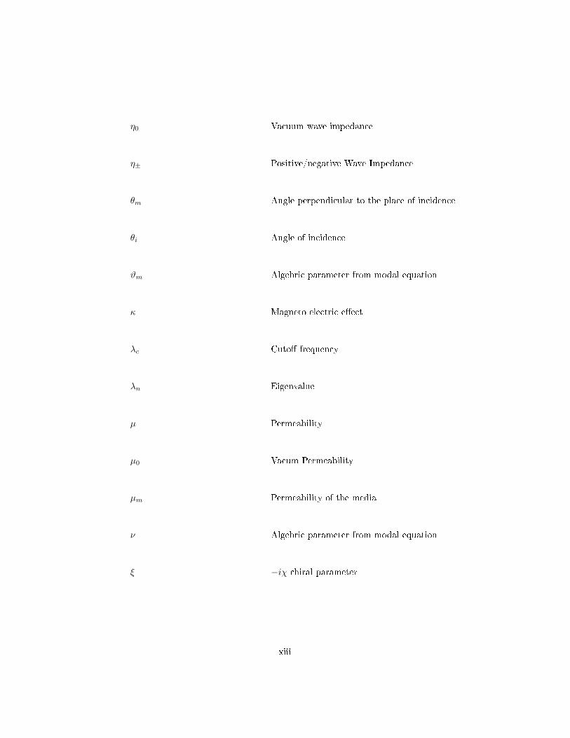
η0 Vacuum wave impedance
η± Positive/negative Wave Impedance
θm Angle perpendicular to the place of incidence
θi Angle of incidence
ϑm Algebric parameter from modal equation
κ Magneto electric e�ect
λc Cuto� frequency
λn Eigenvalue
µ Permeability
µ0 Vacum Permeability
µm Permeability of the media
ν Algebric parameter from modal equation
ξ −iχ chiral parameter
xiii
Page 15
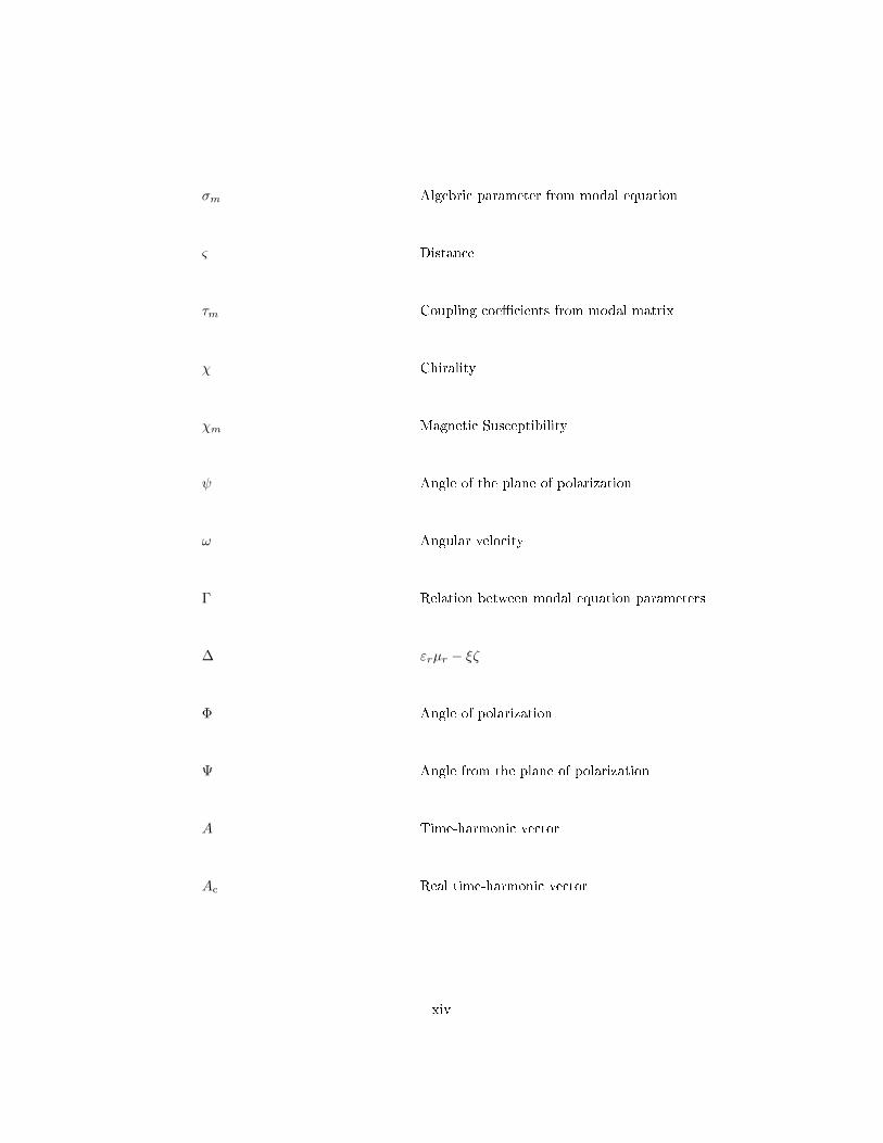
σm Algebric parameter from modal equation
ς Distance
τm Coupling coe�cients from modal matrix
χ Chirality
χm Magnetic Susceptibility
ψ Angle of the plane of polarization
ω Angular velocity
Γ Relation between modal equation parameters
∆ εrµr − ξζ
Φ Angle of polarization
Ψ Angle from the plane of polarization
A Time-harmonic vector
Ac Real time-harmonic vector
xiv
Page 16
As Real time-harmonic vector
a complex vector
ar real time-vector =Ac
ai complex vector =As
a∗ complex conjugate vector
ac real vector
as real vector
B Magnetic Flux Density
C Coupling Matrix
D Electric Flux Density
d Point in the z axis
E0 Initial Electric Field
Ei Electric �eld of the incident wave
xv
Page 17
Ei‖ Component of the incident Electric �eld
Et Component of transmitted Electric �eld
H Magnetic Field Intensity
H0 Initial Magnetic Field Intensity
Ht⊥ Component of transmitted Magnetic �eld
hs Transverse wave number
I Identity matrix
i Imaginary unit
k0 Vacuum wave number
k± Propagation constant
k Versor k
M Modal matrix
n Refractive index
xvi
Page 18
nef E�ective refractive index
p Real vector
< Real complex
R Radius
Rmm Re�ection coe�cient, with mm = 11, 12, ..., 21, 22...
r Complex vector
T T = 2×πω
Tmm Transmission coe�cient, with mm = 11, 12, ..., 21, 22...
t Time variable
t′ Thickness of the chiral slab
u+ Right-hand circularly polarized unit vector
u− Left-hand circularly polarized unit vector
uz Direction of propagation of unit vector
xvii
Page 19
Y1 Chiral admittance of the dielectric medium
Y2 Chiral admittance of the chiral medium
xviii
Page 20
Chapter 1
Introduction
The present chapter it is done a brief overview about the chiral media since the
beginning of its investigation in the early 19th century until the present time.
The motivation and objectives of this dissertation are de�ned and a detailed
information about the organization of the work is reviewed, chapter by chapter.
1
Page 21
1.1 State of the art
A chiral media fall into the class of bi-isotropic (BI) media and when the light of
a linearly polarized plane will rotate as it passes through the medium, interacts
with the state of an electromagnetic waves and couples selectively with either
left or right circularly polarized component, we call this property the optical
activity.
This manifestation of spatial dispersion occurs because the polarization of a
medium at a given point depends on the �eld, not only in that point, but also
in its surroundings.
Although the chiral media belongs to BI medium and presents the same prop-
erties concerning to the characteristic waves and the polarization rotation, not
every BI media is chiral [1].
A new era in physics began in the early 19th century, when Arago (1811) �rst
saw the manifestation of optical activity in a quartz crystal. He observed that
the quartz crystal rotates the plane of polarization of a linearly polarized light
which has passes along the crystal optic axis.
Later, Biot (1812) proved that the optical activity was dependent on the thick-
ness of the crystal plate and on the light wavelength [2].
Fresnel (1821), showed that a linearly polarized light ray of a crystal quartz
separates into two circularly polarized rays of light. He argued that the dif-
ference in the two wave velocities is the cause of the optical activity. He also
tried to justify the di�erent phase velocities for the two circularly polarized
rays. He stated that the di�erent phase velocities could result from a particular
constitution of the refracting medium or integral molecules which established a
di�erence between the sense of right to left or vice-versa.
Pasteur(1840's), began the study of the crystal structure of the materials and
their relation with the optical activity. He postulated that molecules are three-
dimensional objects and that the optical activity of a medium is caused by the
chirality of its molecules.
Hertz (1888), it was natural to look for the rotatory power in the materials that
would be e�ective at these wavelengths, the main question was to know how did
2
Page 22
the wavelengths a�ected the rotatory power.
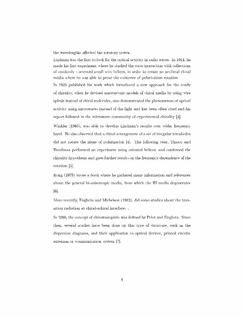
Lindman was the �rst to look for the optical activity in radio waves. In 1914, he
made his �rst experiment where he studied the wave interaction with collections
of randomly - oriented small wire helices, in order to create an arti�cial chiral
media where he was able to prove the existence of polarization rotation.
In 1920 published his work which introduced a new approach for the study
of chirality, when he devised macroscopic models of chiral media by using wire
spirals instead of chiral molecules, also demonstrated the phenomenon of optical
activity using microwaves instead of the light and has been often cited and his
report followed in the microwave community of experimental chirality [3].
Winkler (1965), was able to develop Lindman's results over wider frequency
band. He also observed that a chiral arrangement of a set of irregular tetrahedra
did not rotate the plane of polarization [4]. The following year, Tinoco and
Freedman performed an experiment using oriented helices, and con�rmed the
chirality hypothesis and gave further results on the frequency dependence of the
rotation [5].
Kong (1975) wrote a book where he gathered many information and references
about the general bi-anisotropic media, from which the BI media degenerates
[6].
More recently, Engheta and Michelson (1982), did some studies about the tran-
sition radiation at chiral-achiral interface. ,
In 1990, the concept of chirowaveguide was de�ned by Pelet and Engheta. Since
then, several studies have been done on this type of structure, such as the
dispersion diagrams, and their application to optical devices, printed circuits
antennas or communication system [7].
3
Page 23
In 2003, Tretyakov discussed the possibility of realizing negative refraction by
chiral nihility. The authors �rst proposed the idea to fabricate a metamaterial
composed of chiral particles, such as helical wires [8].
In 2004, Pendry discussed the possibility to achieve negative refraction in chiral
metamaterials. He analyzed the conditions to realize negative refraction in
chiral metamaterials and showed that they are simpler than for the regular
metamaterials, which require both electric and magnetic resonances to have ε
negative and negative µ. In chiral metamaterials, as mentioned above neither ε
nor µ needs to be negative. As long as the chiral parameter χ is large enough,
negative ε can be obtained in chiral metamaterials. Pendry then proposed a
practical model of a chiral metamaterial working in the microwave regime with
twisted Swiss rolls as elemental structures [9].
Now days, important work is being developed in the chiral media , chiral meta-
materials are one of the most interesting subjects that are being explored. The
fact that o�er a simpler route to negative refraction, with a strong chirality, with
neither ε nor µ negative required, because the chirality can replace these condi-
tions, this subject has been constantly approached by researchers. So it becomes
important to analyze the chiral media in order to develop new applications.
The chiral metamaterials with large optical activity have also been proposed
and made for polarization control applications at microwave and optical fre-
quencies. Research groups have been studying chiral metamaterial design with
strong tunable optical activity in a relatively wide frequency bands with low
transmission losses, makes it a very e�cient material for tunable polarization
rotators [10].
Also chiral printed circuits are being explored, there is an example of a four-
port cascaded circuit model, which is mentioned as chiral cascaded circuit, is
presented to represent an isotropic and lossless chiral media. Such a model is
4
Page 24
based on the concept of transmission line and characteristic transformers.
Such a circuit model provides an e�cient way to realize chiral media using
transmission-line circuits and may �nd potential applications in microwave tech-
nologies [circuito].
1.2 Motivation and Objectives
There are certain areas within the electromagnetic research of today containing
potential for diverse new applications in engineering. One of the most interesting
�elds to be explored are the novel materials e�ects.
The progress of theoretical understanding of the wave-material interaction has
been increasing since the 1990's, and the electromagnetic phenomena has been
studied in order to solve new solutions for the problems, specially related to
microwaves.
In Maxwell's theory of macroscopic electromagnetism, material media are de-
scribed phenomenologically by constitutive relations.
Depending on the particular form of the constitutive relations, a medium can
be characterized as homogeneous, inhomogeneous, isotropic, anisotropic, bi-
anisotropic.
The constitutive relations of a bi-anisotropic medium relates D to both E and
B and H to both E and B.
When all four tensors become scalars quantities, the medium may be called
BI, which is the simplest case for reciprocal bi-anisotropic medium. And where
exists magneto electric coupling of the �elds, but the properties of the material
are independent of the directions in space [11].
Chiral materials have been intensively studied since it is widely believed that
they can be used to produce novel microwave devices and structures. Appli-
5
Page 25
cations for chiral materials are, for instance, polarization transformers, phase
shifters and devices that correct the cross polarization in lens antennas.
Some experiments have been done along the years such as the chirosorbTM , that
introduced a novel synthetic material, which was invisible to electromagnetic
energy and has properties which are independent of polarization in the back
scatter direction.
This experiment is useful for radar identi�cation and inverse scattering prob-
lems, the location and shape of targets can be detected from a knowledge of
waves re�ected or scattered from the target boundaries. These boundaries can
be looked on as variations or discontinuities of electrical parameters. If the re-
�ected or scattered waves can be reduced signi�cantly, the location and shape of
the boundaries, and consequently targets, will not be detected. In other words,
the targets will become 'invisible' [12].
This work aims to understand the theoretical interaction between waves and
chiral media. From the study of chiral structures it is possible to observe the
e�ect of polarization rotation, the propagation modes and cuto� frequencies.
The re�ection and transmission of dielectric/chiral interface are also analyzed
as well as the Breweter's angle in�uence with chirality.
BI structures are also observed as the parallel-plate and gounded chiroslab which
is importance once it gives us more information and knowlege for chirowave
structures.
The motivation of this work is to understand the theoretical concept of chiral
media, in order to provide knowledge to pursue potential applications of the
chiral materials to optical devices or waveguides and printed-circuits in the
microwave and millimeter wave regime.
6
Page 26
1.3 Structure of the dissertation
The present dissertation is composed by �ve chapters.
The introduction referres to a general description of the chiral media since the
discovery of the chiral properties until the evolution of the present days.
This section explains when was the chiral media �rst observed and what studies
have been done to understand their properties and characteristics.
Starting in the early nineteenth century where Arago (1811) started to observe
the phenomenon of optical activity in a crystal quartz until the actual days
where many experiments and studies have been done in several areas for the
chiral media, such as the polymer science and manufacture of arti�cial dielectric,
for the application at the microwave or millimeter wavelengths.
In this chapter is also expressed the motivations and objectives of this disserta-
tion, the reason for studying chiral media and some speci�c properties of chiral
media that will be addressed.
The second chapter the basic notions of the BI media are presented.
Applying Maxwell's equation in chiral media, properties of this media behavior
are reviewed such as the optical activity, the wave�eld postulates, the charac-
teristic waves and the left and right polarizations describing mathematically.
All the knowledge of these properties will allow us to understand some results
of the following chapters.
In the third chapter it is represented the mathematical problem of re�ection
and transmissions through a simple isotropic media (SIM) - Chiral media. The
study of this chiral media is based on a Cartesian coordinate system (x, y, z).
When a plane wave is incident upon a boundary between a dielectric and a chiral
medium splits into two transmitted waves proceeding into the chiral medium,
and a re�ected wave propagating back into the dielectric.
7
Page 27
The study of re�ection and transmission between SIM and chiral media will be
done by determining the re�ection and transmission coe�cients.
In this chapter, it is also possible to observe the in�uence of chirality over
Brewster's angle.
In the fourth chapter a study of a method for the analysis of a BI structure for
planar waveguides is done . This method is general for all the BI homogeneous
layered waveguides, this method is based on a 2× 2 coupling matrix eigenvalue
problem and it will be solved for a parallel-plate and also grounded chiral slab.
The parallel-plate is a simpler problem to be solved since the structure is sym-
metrical, for a grounded chiral slab the structure is more complex since it is
consider the Perfect electromagnetic conductor (PEC) on the ground, and the
top of the chiral slab it is in contact with the air.
For both of the structures the modal equations is obtained in order to observe
the propagation surface modes, and the cuto� frequency is
In the �fth and last chapter, all the results from the second, third and fourth
chapter are discussed and the main conclusions explained so that the most
interesting results may be useful to further works.
1.4 Main contributions
The research done in the electromagnetic theory has been increasing its relevance
on the study of complex materials as the chiral, pseudo-chiral, omega and all
the bi-anisotropic media in general.
The chiral media, is a reciprocal BI media that can be de�ned and described
through Maxwell electromagnetic equations. Although this subject has been
studied since the 19th century, many properties and new applications are being
studied in the actual days.
8
Page 28
This work aims to give an overview about chiral media in general. The concept
of optical activity, polarization, waveguides and characteristic waves is analyzed
based on Maxwell's equations.
Apart from describing chiral media characteristics, the concept of re�ection and
transmission of a monochromatic plane wave upon a simple isotropic media
(SIM)/chiral interface is also observed. This is an interesting problem since it
can be related to a chiral optical �ber with a dieletric core.
Adopting a four-parameter model in the EH set of constitutive relations char-
acterizing a BI medium examples of applications are given in order to analyze
the surface modes of a parallel-plate chirowaveguide and a grounded chiroslab.
The study of concepts and application of chiral theoretical basic problems allows
to complement and resume chiral properties, and hopefully will contribute to
the continuity of more and more complex studies.
9
Page 30
Chapter 2
Bi-isotropic and chiral media
properties
In the present chapter basic notions between the bi-isotropic medium (BI) and
the electromagnetic �eld will be presented. A homogeneous BI medium can be
split into wave�elds, each of which sees the BI medium as an isotropic medium,
which becomes easier to solve electromagnetic problems. The chiral media be-
longs to BI medium and presents the same properties such as, the characteristic
waves and the polarization rotation.
11
Page 31
2.1 Introduction
The BI materials have the special optical property that they can twist the
polarization of light in either refraction or transmission, which is called the
optical activity.
This does not mean all materials with twist e�ect fall in the BI class. The twist
e�ect of the class of BI materials is caused by the chirality and non-reciprocity
of the structure of the media, in which the electric and magnetic �eld of an
electromagnetic wave (or simply, light) interact in an unusual way.
The BI media are birefringent which explains the two eigenvalues with di�erent
propagation factors.
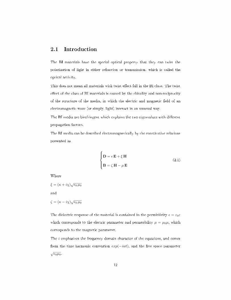
The BI media can be described electromagnetically by the constitutive relations
presented as
D = εE + ξH
B = ζH− µE(2.1)
Where
ξ = (κ+ iχ)√ε0 µ0
and
ζ = (κ− iχ)√ε0 µ0
The dielectric response of the material is contained in the permittivity ε = ε0ε
which corresponds to the electric parameter and permeability µ = µ0µ, which
corresponds to the magnetic parameter.
The i emphasizes the frequency domain character of the equations, and comes
from the time-harmonic convention exp(−iwt), and the free-space parameter
√ε0µ0.
12
Page 32
The chirality parameter is represented by χ, it measures the degree of the hand-
edness of the material and κ describes the magneto electric e�ect.
In many books, κ is considered the chirality of the material, but in this case, it
will be represented by χ.
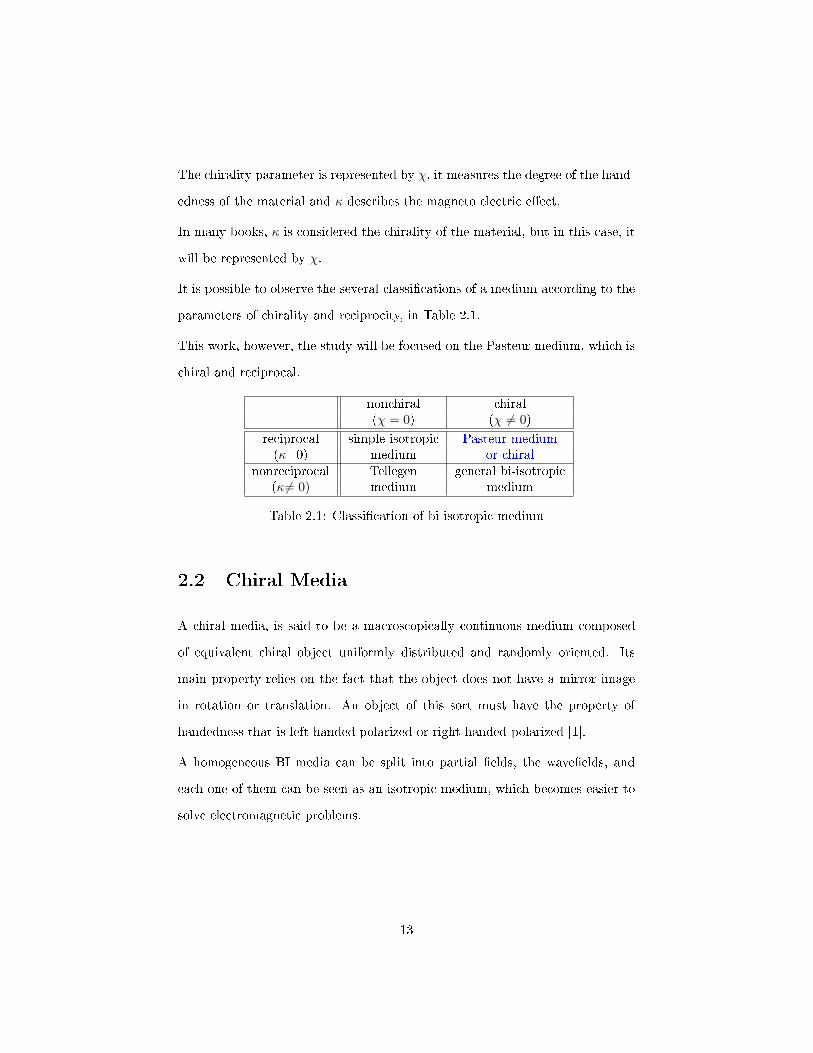
It is possible to observe the several classi�cations of a medium according to the
parameters of chirality and reciprocity, in Table 2.1.
This work, however, the study will be focused on the Pasteur medium, which is
chiral and reciprocal.
nonchiral chiral(χ = 0) (χ 6= 0)
reciprocal simple isotropic Pasteur medium(κ=0) medium or chiral
nonreciprocal Tellegen general bi-isotropic(κ6= 0) medium medium
Table 2.1: Classi�cation of bi isotropic medium
2.2 Chiral Media
A chiral media, is said to be a macroscopically continuous medium composed
of equivalent chiral object uniformly distributed and randomly oriented. Its
main property relies on the fact that the object does not have a mirror image
in rotation or translation. An object of this sort must have the property of
handedness that is left-handed polarized or right-handed polarized [1].
A homogeneous BI media can be split into partial �elds, the wave�elds, and
each one of them can be seen as an isotropic medium, which becomes easier to
solve electromagnetic problems.
13
Page 33
The BI constitutive relations and the chiral media, the constitutive relations are
the same, (2.1) and can be related to Maxwell equations as
∇×E = i ωB
∇×H = −i ωD
(2.2)
and considering the constitutive relations of the BI media (2.1), we can rewrite
Maxwell's equations (2.2), for both electric and magnetic �eld in frequency
domain as it is shown below
∇×E = i ω µH− i ω ζE
∇×H = −i ω εE + i ω ξH
(2.3)
2.2.1 Wave�eld postulates
One of the mains aspects of the homogeneous unbounded electromagnetic wave
propagation, is the de�nition of their characteristic waves.
In the case of the chiral media, it is important to analyze the two characteristic
waves to determine its polarization.
In order to verify the rotation of polarization, the electric and magnetic �eld
vectors E and H will be de�ned with two other �eld quantities. The wave�elds
will be decomposed in parameters represented as �plus� and �minus�, which
combined will represent the total �eld as
E = E+ + E−
H = H+ + H−
(2.4)
14
Page 34
Considering chiral media as equivalent isotropic media, we will obtain two waves,
which will be designated as �positive� and �negative� waves.
Satisfying the Maxwell equations of an achiral media, where there is no coupling,
it is possible to obtain the positive and negative wave as
”positive”wave
∇×E+ = i ω µ+ H+
∇×H+ = −i ω ε+ E+
(2.5)
”negative”wave
∇×E− = i ω µ−H−
∇×H− = −i ω ε−E−
(2.6)
Considering the constitutive relations from the equation (2.1), we consider an
equivalent isotropic media with the parameters ε+, ε−, µ+, µ− , the medium
parameters will satisfy the conditions written below [13]
D+ = εE+ + ξ
√ε0µ0 H+ = ε+E+
B+ = ζ√ε0µ0 E+ + µH+ = µ+ H+
(2.7)
D− = εE− + ξ
√ε0µ0 H− = ε−E−
B− = ζ√ε0µ0 E− − µH− = µ−H−
(2.8)
After eliminating the �eld vectors we can observe that the equivalent parameters
ε±, and µ± must satisfy the conditions below
(ε− ε+)(µ− µ+)− ξζ = 0
(ε− ε+)(µ− µ+)− ξζ = 0
(2.9)
Also, the wave�eld vectors must satisfy relations which can be written in the
15
Page 35
form
E± = i η±H± (2.10)
The wave impedance parameters are de�ned as
η+ = −i ξ
ε+−ε = −iµ+−µζ
η− = i ξε−−ε = iµ−−µ
ζ
(2.11)
Since the electric �eld and magnetic �eld are interrelated through equation
(2.10), certain restrictions for the parameters arise. Inserting (2.10) with the
H+ of (2.5), one obtains
5×H+ + i ω ε+ E+ = −i 1
η+(∇×E+ + ω ε+ η
2+H+) = 0 (2.12)
which should coincide with the equation from (2.5). This leads to the following
relation
η± =
√µ±ε±
(2.13)
Replacing (2.11) and (2.15)
η2± = − (µ± − µ)2
ζ2=µ±ε±
=µ±
ε+ ξζµ±−µ
(2.14)
Considering (2.13) one has
η± = η− = η =
õ
ε(2.15)
16
Page 36
So the two characteristic waves have a constant of propagation stated in the
following equation
k± = n±k0 (2.16)
Where k+corresponds to the positive wave and k− to the negative wave.
2.2.2 Polarization
Since the wave�elds components of a plane wave do not couple in a homogeneous
medium, we can analyze them as an independent plane wave which can be
written as the expressions below
E±(r)= E±exp(ik± · r) (2.17)
H±(r)= H±exp(ik± · r) (2.18)
it is assumed that components propagate in the same direction de�ned by the
real unit vector k as mentioned
k± = k±k = (n±k0)k (2.19)
Unlike the simple isotropic media, the solutions from (2.17) and (2.18) are only
possible for certain polarizations (circular), which coincide with those of the
wave�elds [13].
De�ning a distance
ς = k · r (2.20)
17
Page 37
The characteristic waves may be written as
E+(r) = [E+exp( i χ k0 ς)]exp( i n k0 ς)
E−(r) = [E−exp(−i χ k0 ς)]exp( i n k0 ς)(2.21)
In this case, the Maxwell equations from (2.5), (2.6), will obtain the following
values
k± ×E± = ωµ±H±
k± ×H± = −ωε±E±(2.22)
where E and H become
E± = − k±
ω ε±(k×H±)
H± = k±ω µ±
(k×E±)
→
E± = −η±(k×H±)
H± = 1η±
(k×E±)
(2.23)
Since the TEMwaves correspond to no electric nor magnetic �eld in the direction
of propagation
TEM wave→ k ·E± = k ·H± = 0 (2.24)
The orthogonal relations will be given by
E+ ·H+ = 0
E− ·H− = 0
(2.25)
From (2.10) and (2.15), of electric and magnetic �eld vectors of the wave�elds
components, from Maxwell equations
18
Page 38
H+ = − i
ηE+
H− = iηE−
(2.26)
Based on (2.23), the electric �eld satis�es
k×E+ = −iE+
k×E− = iE−
(2.27)
where the E �eld is orthogonal to the direction of propagation
E+ ·E+ = 0
E− ·E− = 0
(2.28)
According to (2.28), each characteristic wave has circular polarization (CP). To
determine which wave corresponds to the right or left polarization, let us con-
sider a real vector notation, which will be suitable for describing time-harmonic
vectors, which are real vectors rotating along an ellipse in a plane.
A(t) = Accos(ωt) + Assin(ωt)
It is possible to establish a relation between a complex vector with two real
vectors a = ar + iai, where a real time-harmonic vector is de�ned as
A(t) = <{a exp(−iωt)}
= <{(ar + iai)[cos(ωt)− i sin(ωt)]}
= arcos(ωt) + aisin(ωt)
19
Page 39
so Ac = ar and As = ai. Inverting the relation above T = 2×πω , one gets
a = A(0) + iA(T
4) = Ac+iAs (2.29)
The complex conjugate of a complex vector, a∗ = ac − ias, corresponds to the
time-harmonic vector A(−t) which means that the sense of rotation along the
ellipse is reversed from the A(t).
This a vector it will be very useful to determine the polarization of vector A(t).
Some notes to be kept in mind are the fact that
Ac ×As = 0 the vectors may be parallels or one of them might be null.
Ac ×As 6= 0 the vectors will de�ne the rotation of the vector A(t).
If we consider the Linear Polarization (LP),
Ac ×As = 0,
since Ac = ar and As = ai, we obtain a LP, if ar × as = 0.
By other hand the vectors
a× a∗ = (ar + iai)× (ar − iai) = −i(ar × ai) = −2i(ar × ai)
∴ ar × ai = 0⇔ a× a∗ = 0
Then we are able to de�ne
∴ LP → a× a∗ = 0 (2.30)
For the Ac ×As 6= 0 case it is possible to obtain the elliptical and the circular
polarization.
20
Page 40
For the particular case of the CP, we consider
| A(t) |2=| Ac |2 cos2(ωt)+ | As |2 sin2(ωt) + (Ac ·As)sin(2ωt) = R2
where R represents the radius.
For t=0, the| Ac |= R;
For t=T4 , the | As |= R.
Then,| Ac |= | As |= R
where CP is
CP →| A(t) |2= R2 + (Ac ·As)sin(2ωt) = R2
which implies
Ac ·As = 0
∴ CP → a · a = 0 (2.31)
then
a · a = ar × iai · (ar + iai) = |ar|2 − |ai|2 + 2i(arai)
Therefore,
a · a = 0 implies that | ar |2=| ai |2= 0.
As mentioned before Ac = ar and As = ai , where we can conclude that PC
corresponds to (2.31).
From this section of circular polarization in chiral media, we can resume it
through the Table 2.3
21
Page 41
polarization condition acronym
linear a× a∗ LPcircular a · a = 0 CPellyptical other EP
Table 2.3: Conditions of polarization
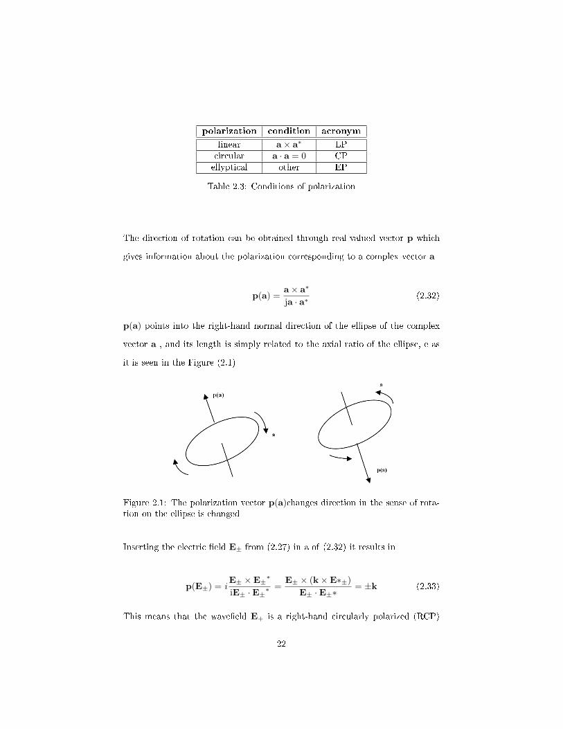
The direction of rotation can be obtained through real-valued vector p which
gives information about the polarization corresponding to a complex vector a
p(a) =a× a∗
ja · a∗(2.32)
p(a) points into the right-hand normal direction of the ellipse of the complex
vector a , and its length is simply related to the axial ratio of the ellipse, e as
it is seen in the Figure (2.1)
Figure 2.1: The polarization vector p(a)changes direction in the sense of rota-tion on the ellipse is changed
Inserting the electric �eld E± from (2.27) in a of (2.32) it results in
p(E±) = iE± ×E±
∗
iE± ·E±∗=
E± × (k×E∗±)
E± ·E±∗= ±k (2.33)
This means that the wave�eld E+ is a right-hand circularly polarized (RCP)
22
Page 42
vector with respect to the direction of propagation u. On the other hand E−
is left hand (LCP) vector, since it is right-handed when looking in the −u
direction.
2.2.3 Polarization Rotation
In the magneto plasmonics and iron it is observable the Faraday rotation e�ect,
which is an interaction between light and a magnetic �eld in a medium.
The Faraday e�ect causes a rotation of the plane of polarization which is lin-
early proportional to the component of the magnetic �eld in the direction of
propagation.
The chiral media it is observable the optical activity. Although the both e�ects
cause a rotation in the polarization, the �rst one has a non-reciprocal e�ect,
while the second has a reciprocal e�ect [13].
The polarization rotation in chiral media it is only possible due to the circular
birefringence, which means that we get circularly polarized TEM waves, which
”positive”wave→ k+ = n+k0 = (n+ χ)k0 → RCP
”negative”wave→ k+− = n−k0 = (n− χ)k0 → LCP
We assume that the direction of propagation along the positive z axis, i.e.
u = uz. Taking linearly polarized electric �eld with an amplitude vector E sat-
isfying E.uz =0 we can decompose in into two circularly polarized unit vector
when looking in the direction of uz
u+ =1√2
(ux − iuy)
23
Page 43
u− =1√2
(ux + iu)
where u+ is a RCP and u−is a LCP unit vector when looking in the uz.
A plane wave polarized along ux at z=0 is de�ned by
E = uxE = (u+ + u−)E√2
or
E(z = 0) =E0
2(x+iy) +
E0
2(x−iy) (2.34)
Taking into account the direction of propagation, the �eld z = d, is given by
E(z = d) =E0
2(x+iy)exp(in+k0d) +
E0
2(x−iy)exp(in−k0d) (2.35)
To simplify, one can de�ne
φ =1
2(k+ + k−)d = (n+ + n−)k0d
Ψ =1
2(k+ − k−)d = (n+ − n−)k0d
where
φ+ Ψ = k+d = n+k0d
φ−Ψ = k−d = n−k0d
⇒
exp(in+k0d) = exp(iφ)× exp(iΨ)
exp(in−k0d) = exp(iφ)× exp(−iΨ)
Where (2.35) can be replaced by
24
Page 44
E(d) =E0
2[(x+iy)exp(iΨ) + (x−iy)exp(−iΨ)] exp(iφ) (2.36)
=E0
2{x[exp(iΨ) + exp(−iΨ)] + iy[exp(iΨ)− exp(−iΨ)]} exp(iφ)
= E0x[cos(Ψ)− ysin(Ψ)]exp(iφ)
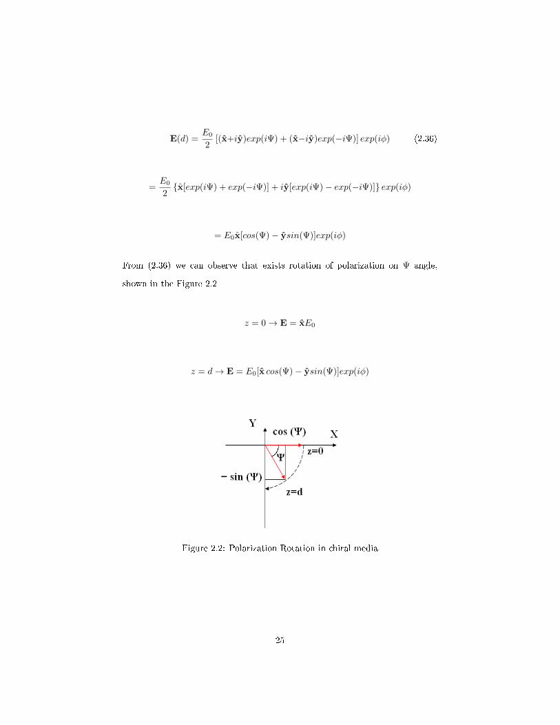
From (2.36) we can observe that exists rotation of polarization on Ψ angle,
shown in the Figure 2.2
z = 0→ E = xE0
z = d→ E = E0[x cos(Ψ)− ysin(Ψ)]exp(iφ)
Figure 2.2: Polarization Rotation in chiral media
25
Page 46
Chapter 3
Re�ections and Transmissions
between a simple planar
interface and chiral media
When a plane wave is incident upon a boundary between a dielectric and a
chiral medium it splits into two transmitted waves proceeding into the chiral
medium, and re�ected wave propagating back into the dielectric.
In this chapter it will be analyzed the behavior of the re�ection and transmission
of a monochromatic wave who is obliquely incident upon the interface between
simple isotropic media (SIM) and chiral.
27
Page 47
Introduction
A plane wave is considered to be a good approximation at a large distance of
their sources and it is also a simple solution of Maxwell's equations, to represent
wave propagation in chiral media.
In the case of a incident plane wave passing in a dieletric/chiral interface, the
best way to mathematically formulate the problem of re�ection and transmission
is using a cartesian coordinate system (x,y,z).
Since the chiral medium is isotropic, there is no preferred direction of propa-
gation, so usually the monochromatic plane wave propagates along the positive
z-axis of the Cartesian system.
In order to calculate the amplitude of the re�ected and transmitted waves and
their polarization properties the boundary conditions must be applied to the
electric and magnetic �elds at planar interface, as shown in Figure 3.
The chiral media constitutive relations as mentioned on the previous chapter
are given by
D = ε0εE + i
√ε0µ0χH
B = µ0µH−i√ε0µ0χE
(3.1)
28
Page 48
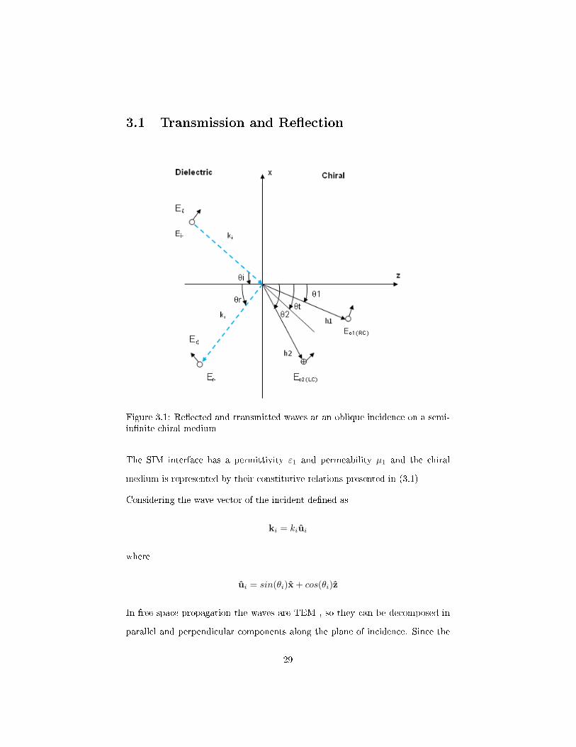
3.1 Transmission and Re�ection
Figure 3.1: Re�ected and transmitted waves at an oblique incidence on a semi-in�nite chiral medium
The SIM interface has a permittivity ε1 and permeability µ1 and the chiral
medium is represented by their constitutive relations presented in (3.1)
Considering the wave vector of the incident de�ned as
ki = kiui
where
ui = sin(θi)x + cos(θi)z
In free space propagation the waves are TEM , so they can be decomposed in
parallel and perpendicular components along the plane of incidence. Since the
29
Page 49
two transmitted waves are circularly polarized, the electric and magnetic �eld
can be written as [15].
Ei = Ei0exp(iki.r) = Ei0exp[iki(xsinθi + zcosθi] (3.2)
With
Ei0 = Ei⊥ + Ei‖ = Ei⊥y + Ei‖(cosθix− sinθiz) (3.3)
and
Hi = Hi0exp(iki.r) = Hi0exp[iki(xsinθi + zcosθi)] (3.4)
where
Hi0 = Y1(ui ×Ei0) = Y1[Ei‖y − Ei⊥(cosθix− sinθiz) (3.5)
where Y1 is the chiral admittance of the dielectric medium, given by
Y1 = Y0
√ε1µ1
(3.6)
The wave vector of the re�ected wave is
kr = krur
where
ur = sin(θr)x− cos(θr)z
and
30
Page 50
Et1 = E01(cos θ1ex + sin θ2ez + iey) (3.7)
Ht1 = −iY2E01(cos θ1ex + sin θ1ez + iey) (3.8)
Et2 = Et2(cos θ2ex + sin θ2ez − iey) (3.9)
Ht2 = −iY2Et2(cos θ2ex + sin θ2ez − iey) (3.10)
Since the two transmitted waves are circularly polarized, they can be written as
Et = E01exp[ih1(z cos θ1 − x sin θ1)] + E02exp[ih2(z cos θ2 − x sin θ2)] (3.11)
Ht = H01exp[ih1(z cosθ1 − x sin θ1) + H02exp[ih2(z cos θ2 − x sin θ2)] (3.12)
where
E01 = E01(cos θ1ex + sin θ2ez + iey) (3.13)
H01 = −iZ−12 E01(cos θ1ex + sin θ1ez + iey) (3.14)
and
31
Page 51
E02 = E02(cos θ2ex + sin θ2ez +−iey) (3.15)
H02 = −iZ−12 E02(cos θ2ex + sin θ2ez − iey) (3.16)
Here Y2 is the chiral admittance of the chiral medium, given by
Y2 = Y0
√ε2µ2
(3.17)
The parameters from the incident wave are known. In order to �nd the complex-
constant amplitude vectors of the re�ected and transmitted waves, the boundary
conditions for the tangential x and y components of the electric and magnetic
�elds, have to be applied at the interface
(Ei + Er)× z = Et × z (3.18)
(Hi + Hr)× z = Ht × z (3.19)
The conditions above (3.18) and (3.19) can only be applied if
ki sinθi = kr sinθr = k01sinθ1 = k02sinθ2 (3.20)
which is Snell's law.
Based on (3.20) relations obtained are given by
Ei‖ cosθi + Er‖ cosθi = E01cosθ1 + E02cosθ2 (3.21)
32
Page 52
Ei⊥ + Er⊥ = i (E01 − E02) (3.22)
Y1(Ei‖ − Er‖) = Y2(E01 + E02) (3.23)
Y1(Ei⊥ − Et⊥) cosθi = iY2(E01cosθ1 − E02cosθ2) (3.24)
That can also be represented by
0 −cosθi cosθ1 cosθ2
−1 0 i −i
0 Y1 Y2 Y2
Y1cosθi 0 iY2cosθ1 −iY2cosθ2
Er⊥
Er‖
Et1
Et2
=
Ei⊥cosθi
Ei⊥
Y1Ei‖
Y1Ei⊥cosθi
(3.25)
The expressions for Er⊥ , Er‖, E01, E02 can be written according to the compo-
nents of the incident waves as expressed below, where the re�ection and trans-
mission coe�cients matrix can obtained.
Er⊥
Er‖
=
R11 R12
R21 R22
Ei⊥
Ei‖
(3.26)
33
Page 53
Et1
Et2
=
T11 T12
T21 T22
Ei⊥
Ei‖
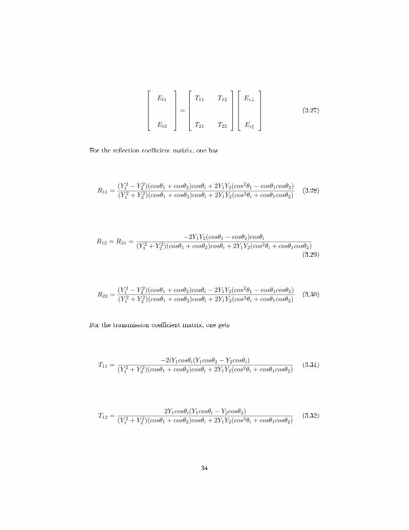
(3.27)
For the re�ection coe�cient matrix, one has
R11 =(Y 2
1 − Y 22 )(cosθ1 + cosθ2)cosθi + 2Y1Y2(cos2θ1 − cosθ1cosθ2)
(Y 21 + Y 2
2 )(cosθ1 + cosθ2)cosθi + 2Y1Y2(cos2θi + cosθ1cosθ2)(3.28)
R12 = R21 =−2Y1Y2(cosθ1 − cosθ2)cosθi
(Y 21 + Y 2
2 )(cosθ1 + cosθ2)cosθi + 2Y1Y2(cos2θi + cosθ1cosθ2)
(3.29)
R22 =(Y 2
1 − Y 22 )(cosθ1 + cosθ2)cosθi − 2Y1Y2(cos2θ1 − cosθ1cosθ2)
(Y 21 + Y 2
2 )(cosθ1 + cosθ2)cosθi + 2Y1Y2(cos2θi + cosθ1cosθ2)(3.30)
For the transmission coe�cient matrix, one gets
T11 =−2iY1cosθi(Y1cosθ2 − Y2cosθi)
(Y 21 + Y 2
2 )(cosθ1 + cosθ2)cosθi + 2Y1Y2(cos2θi + cosθ1cosθ2)(3.31)
T12 =2Y1cosθi(Y1cosθi − Y2cosθ2)
(Y 21 + Y 2
2 )(cosθ1 + cosθ2)cosθi + 2Y1Y2(cos2θi + cosθ1cosθ2)(3.32)
34
Page 54
T21 =2iY1cosθi(Y1cosθ1 − Y2cosθi)
(Y 21 + Y 2
2 )(cosθ1 + cosθ2)cosθi + 2Y1Y2(cos2θi + cosθ1cosθ2)(3.33)
T22 =2Y1cosθi(Y1cosθi + Y2cosθ1)
(Y 21 + Y 2
2 )(cosθ1 + cosθ2)cosθi + 2Y1Y2(cos2θi + cosθ1cosθ2)(3.34)
When the incident wave falls normally on the interfaces, i.e., θi = 0, the expres-
sions above, get reduced to
R11 = R22 =1− (Y1Y2)
1 + (Y1Y2)(3.35)
T11 = −iT22 =−i
1 + (Y1Y2)(3.36)
T12 = −iT21 =1
1 + (Y1Y2)(3.37)
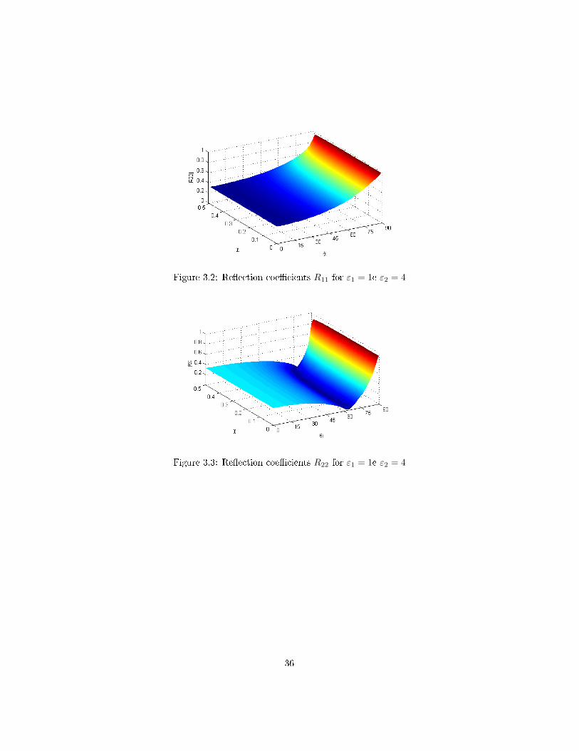
To visualize the relations of the equations from (3.28) to (3.34), three dimen-
sional graphs are done with the chirality parameter χ and θi as the variables.
The permittivity from the media 1 and 2 are ε1 = 1 and ε2 = 2 and µ1 = µ2 = 1.
35
Page 55
Figure 3.2: Re�ection coe�cients R11 for ε1 = 1e ε2 = 4
Figure 3.3: Re�ection coe�cients R22 for ε1 = 1e ε2 = 4
36
Page 56
Table 3.1: Re�ection coe�cients R12 = R21 for ε1 = 1e ε2 = 4
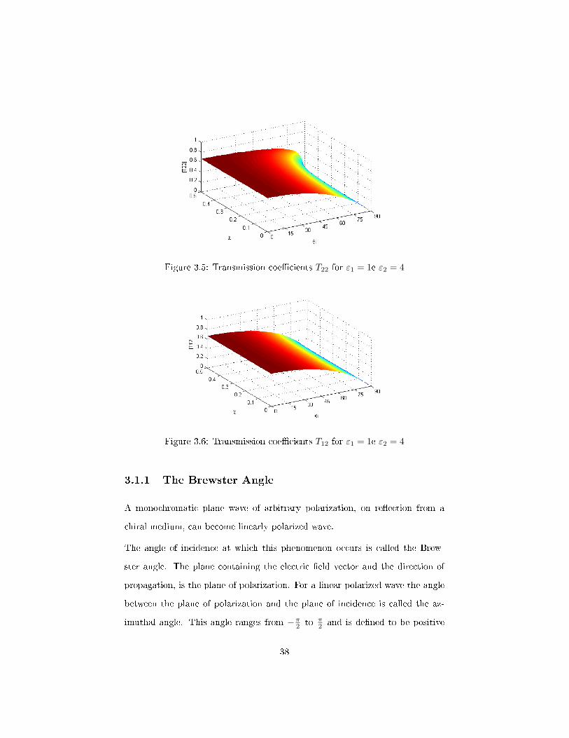
For the transmission coe�cients the same variables will be used which is χ and
θi , and also the same parameters ε1 = 1 e ε2 = 4.
Figure 3.4: Transmission coe�cients T11 for ε1 = 1e ε2 = 4
37
Page 57
Figure 3.5: Transmission coe�cients T22 for ε1 = 1e ε2 = 4
Figure 3.6: Transmission coe�cients T12 for ε1 = 1e ε2 = 4
3.1.1 The Brewster Angle
A monochromatic plane wave of arbitrary polarization, on re�ection from a
chiral medium, can become linearly polarized wave.
The angle of incidence at which this phenomenon occurs is called the Brew-
ster angle. The plane containing the electric �eld vector and the direction of
propagation, is the plane of polarization. For a linear polarized wave the angle
between the plane of polarization and the plane of incidence is called the az-
imuthal angle. This angle ranges from −π2 to π2 and is de�ned to be positive
38
Page 58
whenever the direction of rotation of the plane polarization towards the plane
of incidence and the direction of wave propagation form a right-handed screw
[?].
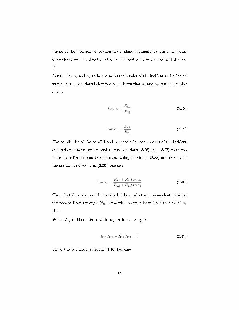
Considering αi and αr to be the azimuthal angles of the incident and re�ected
waves. In the equations below it can be shown that αi and αr can be complex
angles
tanαi =Ei⊥Ei‖
(3.38)
tanαr =Er⊥Er‖
(3.39)
The amplitudes of the parallel and perpendicular components of the incident
and re�ected waves are related to the equations (3.26) and (3.27) from the
matrix of re�ection and transmission. Using de�nitions (3.38) and (3.39) and
the matrix of re�ection in (3.26), one gets
tanαr =R12 +R11tanαiR22 +R21tanαi
(3.40)
The re�ected wave is linearly polarized if the incident wave is incident upon the
interface at Brewster angle (θB), otherwise, αr must be real constant for all αi
[16].
When (84) is di�erentiated with respect to αi, one gets
R11R22 −R12R21 = 0 (3.41)
Under this condition, equation (3.40) becomes
39
Page 59
tanαr =R12
R22=R11
R21(3.42)
And from equations (3.28) to (3.30) into (3.41), one will obtain
(1− (Y1Y2)2)2 cos2θi(cosθ1 + cosθ2)2
= 4(Y1Y2)2(cos2θi − cos2θ1) (cos2θi − cos2θ2)(3.43)
If θ1 and θ2 are written in terms of the angle of incidence θi, then it is possible
to solve a numerical equation in terms of θi, since the angles of the transmitted
waves can be expressed as
θ1 = arcsin
(ki sin θih1
)(3.44)
θ2 = arcsin
(ki sin θih2
)(3.45)
40
Page 60
Chapter 4
A method for the analysis of
bi-isotropic planar waveguides
In this chapter, it is described a general formalism for general bi-isotropic planar
waveguides, and as an example it is studied theoretically the chirowaveguides.
In order to understand some of its properties and using the four-parameter
model in the EH representation for the set of constitutive relations character-
izing a bi-isotropic medium, a 2 × 2 coupling matrix eigenvalue-problems will
be solved in a general description and later will be applied to a parallel-plate
chirowaveguide and a grounded chiroslab. In this case it will be analyzed the
modal equations and the cuto� wavelengths for the guided hybrid modes.
41
Page 61
4.1 Introduction
The problem of guided electromagnetic wave propagation in general bi-isotropic
planar waveguides is described in terms of a linear operator formalism. Based
on the transverse electromagnetic �eld equations an eigenvalue problem is ad-
dressed. An example of a bi-isotropic planar waveguide is a chirowaveguide.
The concept of chirowaveguide was de�ned in the early 90's when the scienti�c
community showed a systematic interest in the electromagnetic properties and
applications of these special isotropic materials.
A chirowaveguide can be a cylindrical waveguide �lled with homogeneous isotropic
chiral material. The electromagnetic chirality of the material inside the waveg-
uide has several important features which were already analyzed, such as the
re�ection and transmission of guided electromagnetic waves, the e�ect of chiral
material loss on guided electromagnetic modes, dispersion relations and cut-o�
frequencies.
It was also shown that the Helmholtz equations for the longitudinal components
of electric and magnetic �elds are always coupled and consequently in these
waveguides, individual transverse electric (TE), transverse magnetic (TM), or
transverse electromagnetic (TEM) modes cannot be supported [7].
The interest on this structure besides the academic one, resides in the fact that
are some potential applications of chiral materials to integrate optical devices,
optical waveguides and printed-circuit elements.
In this present case, from Maxwell curl equations for source free regions, the
analysis of guided hybrid modes in a bi-isotropic layered structures is reduced
to a 2× 2 coupling matrix eigenvalue problem [17].
The structures to be studied are the parallel-plate chirowaveguide, consisting
of two parallel perfectly conducting planes �lled with a lossless, homogeneous,
42
Page 62
isotropic chiral material, and the grounded chiroslab, where the chiral slab is
in contact with the air, which introduces a more complex problem compared to
the parallel-plate [22].
The main feature of the guides is that the propagation modes are always hybrid.
The application of the method
In this present section, the problem of surface waves in a chiral slab will be deter-
mined from the derivation of simple closed-form expressions, than can be used
to general bi-isotropic homogeneous layered waveguides. The time-harmonic
variations of the form exp(−iwt) is considered.
In the frequency domain, considering the Maxwell equations,∇×E = iωB
∇×H = −iωD(4.1)
we can represent the constitutive relations of the chiral media as,D = ε0εE + i√ε0 µ0 χH
B = µ0µH− i√ε0 µ0 χE
(4.2)
∇×E = iωµ0µH + ωχ
√ε0µ0 E
∇×H = −iωε0εE + ωχ√ε0µ0 H
(4.3)
Considering normalized distances, one gets x′ = k0x, z′ = k0z
The structure in�nite and uniform in the y direction ∂∂y = 0 and ∇ = ∂xx− inz,
one has
∇×A∼
=
∣∣∣∣∣∣∣∣x∼
y∼
z∼
∂∂x 0 in
Ax Ay Az
∣∣∣∣∣∣∣∣= x(−inAy) + y(inAx − ∂Az
∂x) + z(
∂Ay
∂x)
43
Page 63
From rot E: ∇×E = iωµ0µH + k0χE
x : −inEy = iωµ0µHx + k0χEx (4.4)
y : −∂Ez∂x
+ inEx = iωµ0µHy + k0χEy (4.5)
z :∂Ey∂x
= iωµ0µHz + k0χEz (4.6)
From rot H: ∇×H = iωε0εE + k0χH
x : −inHy = −iωε0εEx + k0χHx (4.7)
y : −∂Hz
∂x+ inHx = −iωε0εEy + k0χHy (4.8)
z :∂Hy
∂x= −iωε0εEz + k0χHz (4.9)
From (4.4),one obtains
Hx = − n
µZ0Ey + i
χ
µZ0Ex (4.10)
From (4.6), one gets
Hz = −∂Ey∂x
i
Z0µ+ i
χ
Z0µEz (4.11)
44
Page 64
From (4.7), one gets
Ex =Z0n
εHy − i
χZ0
εHx (4.12)
From (4.9), one obtains
Ez = i∂Hy
∂x
Z0
ε− iχZ0
εHz (4.13)
Equations (4.10) and (4.11) will be replaced in equation (4.8) in order to obtain
two di�erential equations depending on y
∂2Ey∂x′2
= −2iωµ0µk0χHy +[−k20(εµ+ χ2) + n2
]Ey (4.14)
The same will be done to equations (4.7) and (4.8) which will be replaced in
equation (4.5), where one obtains
∂2Hy
∂x′2= 2iωε0εk0χEy +
[−k20(εµ+ χ2) + n2
]Hy (4.15)
In order to obtain homogeneous layers from the results above, one has
∂2
∂2x′u (x′) = Cu (x′) (4.16)
where C is the coupling matrix.[∂2Ey
∂2Hy
]=
[k20(εµ+ χ2)− n2 2iωµ0µk0χ
−2iωε0εk0χ k20(εµ+ χ2)− n2
][Ey
Hy
](4.17)
Since this problem is reduced to a 2 × 2 coupling matrix, we can obtain two
eigenvalues of C
det (C− λI) = 0
det
k20(εµ+ χ2)− n2 2iωµ0µk0χ
2iωε0εk0χ k20(εµ+ χ2)− n2
− λ 0
0 λ
= 0
45
Page 65
λn = k20εµ+ k20χ2 ± 2k20
√εµχ− n2 = k2± − n2 (4.18)
λn represents the wave guided propagation and k2± = k20n±.
Introducing modal matrix M for C, where M is [20]
M =
[1 1
τ1 τ2
]
Considering the following transformation
u(x) = Mφ(x′) ∧ Φ = [φ1, φ2]
The equation (4.16) is reduced to
∂2φ(x)
∂x= −M−1CMφ(x′) (4.19)
with M−1
CM = diag(λ1, λ2)
The coupling coe�cients from the modal matrix are given by
τn =λ1 − C11
C12=
C21
λ2 − C22(4.20)
Hence, from equation (4.18) and (4.17), one obtains
τs = −i±k0ωµ0
√ε
µ(4.21)
From equations (4.4) to (4.9) the Ex and Hx will be de�ned as
Ex =n
M(ξEy + µZ0Hy) (4.22)
Hx = − nM
(εEy + ςZ0Hy) (4.23)
The same will be done to Ez and Hz
Ez =i
M
(ξ∂Ey
∂x′+ µ
∂Hy
∂x′
)(4.24)
Hz = − i
M
(ε∂Ey
∂x′+ ζ
∂Hy
∂x′
)(4.25)
Where 4 = εrµr − ξζ
46
Page 66
The �eld components are de�ned as
Ey = φ1 + φ2 (4.26)
Hy = τ1φ1+τ2φ2 (4.27)
4.1.1 Chiral media
For εµ 6= χ2 and χ2 6= 0, only hybrid modes can propagate in the BI planar
waveguides.
TTo solve a wave-guiding problem, apart from the knowledge of the whole struc-
ture, it is necessary to study the boundary conditions.
As stated before, a chiral media is a lossless and reciprocal bi-isotropic media.
For the reciprocity condition, one has [18]
For the reciprocity condition, one has
ξ = −ζ (4.28)
For a lossless BI medium ,
ξ = ζ∗ (4.29)
where the ∗ denotes a complex conjugate.
Although the four-parameter model is chiral, a bi-isotropic medium with (4.28)
and (4.29), should be referred as �chiral medium� instead of �lossless chiral
reciprocal medium�, in which
ξ = −iχ
For the chiral media, the transverse wave number is given by
h2s = β2± + n2 (4.30)
where n is the e�ective refractive index and is given by n = kk0
where k represents
the longitudinal wavenumber.
And β± depends if s = 1 or s = 2 and also depends on chirality.
47
Page 67
β± =√εµ± χ (4.31)
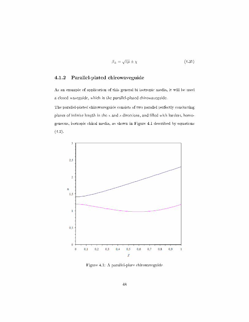
4.1.2 Parallel-plated chirowaveguide
As an example of application of this general bi-isotropic media, it will be used
a closed waveguide, which is the parallel-plated chirowaveguide.
The parallel-plated chirowaveguide consists of two parallel perfectly conducting
planes of in�nite length in the x and z directions, and �lled with lossless, homo-
geneous, isotropic chiral media, as shown in Figure 4.1 described by equations
(4.2).
Figure 4.1: A parallel-plate chirowaveguide
48
Page 68
Observing the Figure 4.1, the direction of propagation is along z axis and the
�eld quantities are all independent of y axis.
Due to the perfectly conducting planes, placed at x′ = 2t′ and x′ = 0, one must
impose that Ey(x′ = 0) = Ez(x′ = 0) = 0 and Ey(x′ = 2t′) = Ez(x′ = 2t′) = 0.
By imposing these boundary conditions, a set of algebraic equations for the
coe�cients A± will be obtained.φ1(x′) = A+[sin(h+x′) + cos(h+x
′)]
φ2(x′) = A−[sin(h−x′)− cos(h−x′)]
(4.32)
The symmetry of the structure, allows the propagating modes to be divided into
even and odd modes.
Considering the odd modesφ1(x′) = A+sin(h+x′)
φ2(x′) = A−sin(h−x′)
(4.33)
The perfectly conducting plane, at x′ = t′ , should have
Ey(x′ = t′) = 0 (4.34)
Ez(x′ = t′) = 0 (4.35)
Imposing the boundary conditions for these �eld components, a homogeneous
set of algebraic equations for the coe�cients A± in (4.33) and 4.24 is obtained.
For the odd modes, one has sin(h+t′) sin(h−t
′)
h+
ε+cos(h+t
′) −h−ε−cos(h−t
′)
A+
A−
=
0
0
(4.36)
Considering the determinant of coe�cients zero, a nontrivial solution is ob-
tained. This leads to the modal equation for the propagating modes.
sin(h+t)
[−h−ε−
cos(h−t′)
]− sin(h−t
′)
[h+ε+
cos(h+t′)
]= 0 (4.37)
This expression can also be de�ned as
49
Page 69
ε−h+ + ε+h−2
sin[(h+ + h−)t′]− ε−h+ − ε+h−2
sin[(h+ − h−)t′] = 0 (4.38)
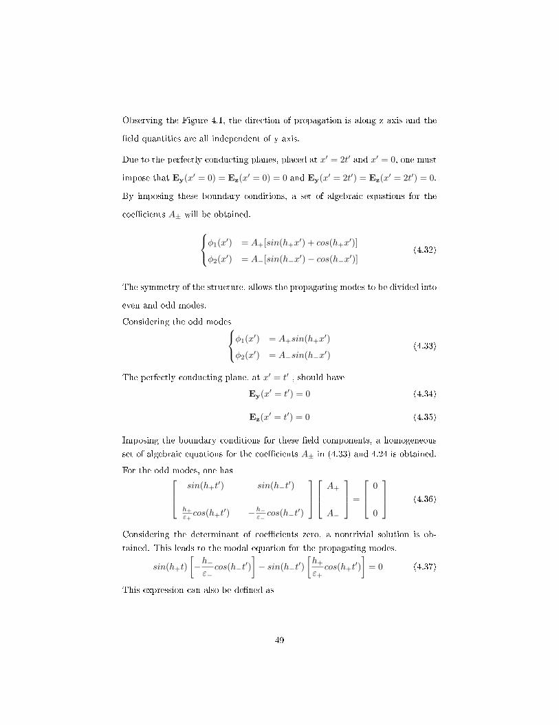
From the expression mentioned above, it is possible to determine the odd prop-
agation modes,
The �gure (4.2) represents the TE and HE modes, while the �gures (4.3) for
χ = 0 and (4.4) χ = 1 represent the hybrid modes.
Figure 4.2: Propagation of the odd modes for χ = 0
50
Page 70
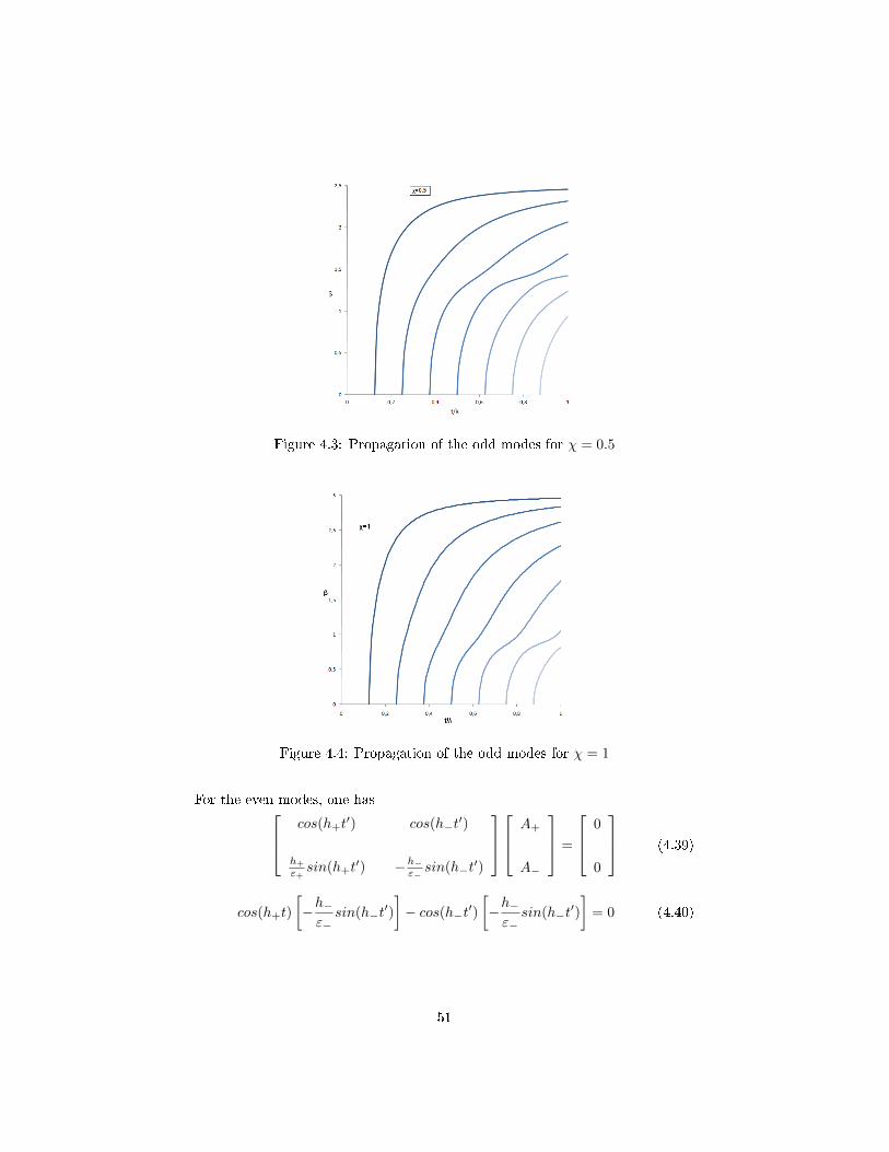
Figure 4.3: Propagation of the odd modes for χ = 0.5
Figure 4.4: Propagation of the odd modes for χ = 1
For the even modes, one has cos(h+t′) cos(h−t
′)
h+
ε+sin(h+t
′) −h−ε−sin(h−t
′)
A+
A−
=
0
0
(4.39)
cos(h+t)
[−h−ε−
sin(h−t′)
]− cos(h−t′)
[−h−ε−
sin(h−t′)
]= 0 (4.40)
51
Page 71
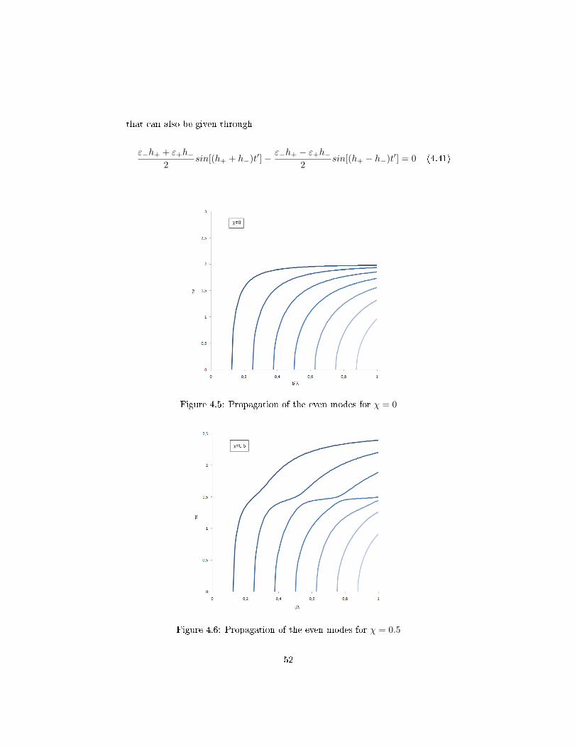
that can also be given through
ε−h+ + ε+h−2
sin[(h+ + h−)t′]− ε−h+ − ε+h−2
sin[(h+ − h−)t′] = 0 (4.41)
Figure 4.5: Propagation of the even modes for χ = 0
Figure 4.6: Propagation of the even modes for χ = 0.5
52
Page 72
Figure 4.7: Propagation of the even modes for χ = 1
From the equation (4.41) we can observe the even propagation modes where �g-
ure (4.5) representsχ = 0, the �gure (4.6) represents χ = 0.5 and (4.7) represents
χ = 1.
At the cuto�, β = 0, which implies (4.30) will be h2s = n2±.
Considering ε± = ε ± ycχ, one can make ε+h+ = ε−h− in (4.37) and (4.40)
modal equations, where the expression obtained is
sin[(β+ + β−)t′] = 0 (4.42)
t
λc=
n
4√εµ
(4.43)
with n = 1, 2, 3, ...
If we consider the parameter tλ as a �xed element, we can observe how the n is
in�uenced by the χ parameter.
For frequency f = 100 GHz, and t = 1mm one has
53
Page 73
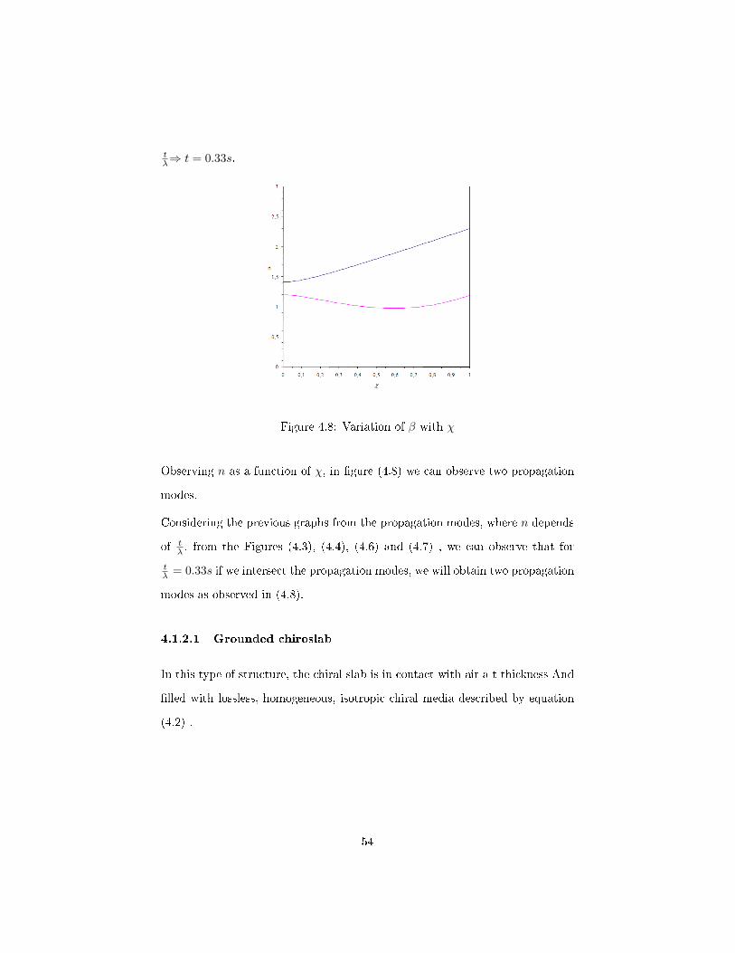
tλ⇒ t = 0.33s.
Figure 4.8: Variation of β with χ
Observing n as a function of χ, in �gure (4.8) we can observe two propagation
modes.
Considering the previous graphs from the propagation modes, where n depends
of tλ , from the Figures (4.3), (4.4), (4.6) and (4.7) , we can observe that for
tλ = 0.33s if we intersect the propagation modes, we will obtain two propagation
modes as observed in (4.8).
4.1.2.1 Grounded chiroslab
In this type of structure, the chiral slab is in contact with air a t thickness And
�lled with lossless, homogeneous, isotropic chiral media described by equation
(4.2) .
54
Page 74
Figure 4.9: Grounded chiroslabguide
For the chiral layer, 0 < x′ < t′, one has
φ1(x) = A[sin(h+x
′) + Γcos(h+x′)]
φ2(x) = A[r sin(h−x′)− Γcos(h−x
′)]
(4.44)
The propagation modes Ey and Hy are de�ned by,
Ey =
φ1 + φ2, 0 < x′ < t′
B exp[−αA(x′ − t)], x′ > t′(4.45)
Hy =
τ1φ1 + τ2φ2, 0 < x′ < t′
−iC exp[−αA(x′ − t)], x′ > t′(4.46)
withdEy
dx anddHy
dx represented by
dEydx
=
φ′1 + φ′2, 0 < x′ < t′
−αAB exp[−αA(x′ − t′)], x > t′(4.47)
55
Page 75
dHy
dx=
τ1φ′1 + τ2φ
′2, 0 < x′ < t′
iCαA exp[−αA(x′ − t′)], x′ > t′(4.48)
The coupling coe�cients for the hybrid modes are given by
τs = −iys (4.49)
ys = ±√ε
µ(4.50)
Where once again, the plus and minus sign represent s=1 and s=2, respectively.
Due to the perfectly conducting plate at x′ = 0, one should have
Ey(x′ = 0) = 0 (4.51)
Ez(x′ = 0) = 0 (4.52)
The r represented on the (4.44) can be obtained through (4.52), where one
obtains
r =h+β−h−β+
(4.53)
For the air region, x′ > t′, one has
Ey(x) = B exp[−αa(x′ − t′)]
Hy(x) = −iC exp[−αa(x′ − t′)](4.54)
56
Page 76
where αa represents an attenuation coe�cient given by
αa = n2 − 1
Considering the continuity of Ez and Hz at x′ = t′, it will be possible to
determine the modal equation as well as Γ mentioned on (4.32)
From Ez (x′ = t′) = Ez (x′ = t′), the following parameters will be de�ned
η1 = αa M y1sin(h1t′)− h1(χ− µy1)cos(h1t
′) (4.55)
ρ1 = αa M sin(h1t′)− h1(χ− µy1)y1cos(h1t
′) (4.56)
ν1 = αa M y1cos(h1t′) + h1(χ− µy1)sin(h1t
′) (4.57)
σ1 = αa M y1cos(h1t′) + h1(χ− µy1)sin(h1t
′) (4.58)
From Hz (x′ = t′) = Hz (x′ = t′) one has
η2 = αa M y2sin(h2t′)− h2(χ− µy2)cos(h2t
′) (4.59)
ρ2 = αa M sin(h2t′)− h2(χ− µy2)y2cos(h2t
′) (4.60)
ν2 = αa M y2cos(h2t′) + h2(χ− µy2)sin(h2t
′) (4.61)
σ2 = αa M y2cos(h2t′) + h2(χ− µy2)sin(h2t
′) (4.62)
57
Page 77
Thus, the modal equation will be written in the following form
(η1 + rη2) (σ1 − σ2)− (ρ1 + rρ2) (ν1 − ν2) = 0 (4.63)
And Γ is de�ned as
Γ = −η1 + rη2ν1 − ν2
= −ρ1 + rρ2σ1 − σ2
(4.64)
Replacing (4.55)-(4.62) the modal equation (4.63) can be simpli�ed, after some
algebraic manipulation and rewritten in the form
2[γ1 − (1− y21)]δ1 + (1 + r2)γ2δ2 − 2(ϑ1 − rϑ2) = 0 (4.65)
where (s=1,2), and
γ1 = (1 + y21) cos(h1t′)cos(h2t
′) (4.66)
γ2 = (1 + y22) sin(h1t′)sin(h2t
′) (4.67)
ϑ1 = y1(α2a M −h21β2
−) sin(h1t′)cos(h2t
′) (4.68)
ϑ2 = y2(α2a M −h22β2
+) sin(h2t′)cos(h1t
′) (4.69)
Through (4.65) it is possible to determine the cuto� wavelength λcof any hybrid
mode.
At cuto� αa = 0 , hence δs = 0 for s = 1, 2, therefore (4.65) will be reduced to
ϑ1 = r ϑ2 from which one gets
58
Page 78
f1(λc) + f2(λc) = 0 (4.70)
where
f1 = q1β−sin q1cos q2 (4.71)
f2 = q2β+sin q2cos q1 (4.72)
and where (s=1,2)
qs = 2πt
λc
√β2± − 1 (4.73)
In (4.73) the plus and minus sing corresponds to s=1 and s=2.
For χ = 0 the cuto� frequencies are given by
(t
λc
)TM=
m
2√εµ− 1
(4.74)
(t
λc
)TE=
2m+ 1
2√εµ− 1
(4.75)
with m = 0, 1, 2, ....
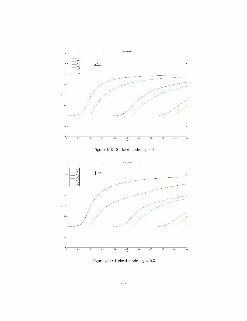
For numerical calculation the following values will be considered, ε = 9 and
µ = 1 and χ will have several values.
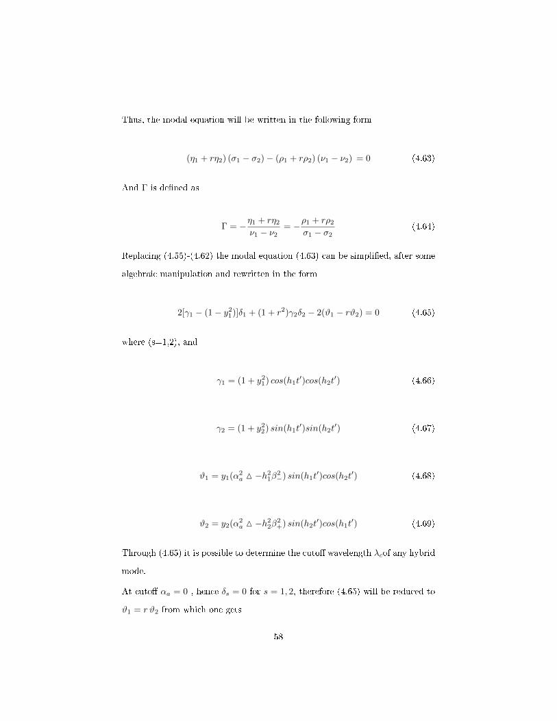
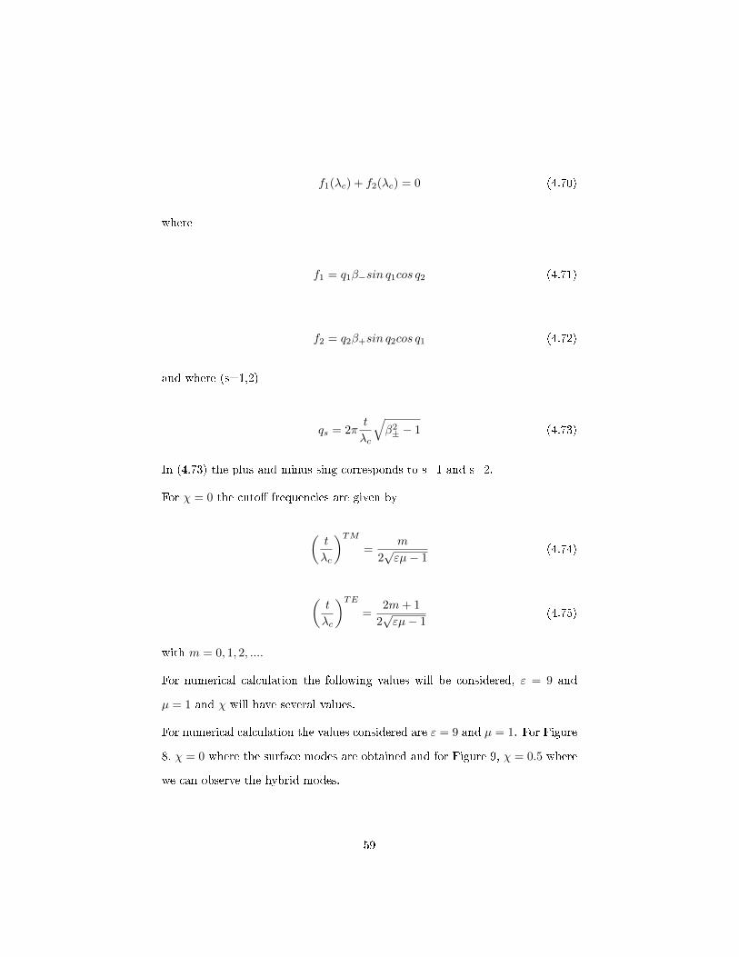
For numerical calculation the values considered are ε = 9 and µ = 1. For Figure
8, χ = 0 where the surface modes are obtained and for Figure 9, χ = 0.5 where
we can observe the hybrid modes.
59
Page 79
Figure 4.10: Surface modes, χ = 0
Figure 4.11: Hybrid modes, χ = 0,5
60
Page 80
Figure 4.12: Hybrid modes, χ = 1
61
Page 82
Chapter 5
Conclusions
In this chapter all the conclusions and results from the previous chapters are
pointed out, as well as future work suggestions.
It will be done an analysis of the concepts that were addressed and the possible
causes and consequences will be determined or discussed.
63
Page 83
In this dissertation the main objective was to study the chiral media and its
main properties and also to characterize the propagation modes of some of the
theoretical problems that were studied, like the parallel-plate chirowaveguide
and the grounded chiroslab.
In the �rst chapter, it was referred the historical content of the chiral media, it is
possible to understand when did the studies began and what were the properties
observed and what experiences have been done along the years, since the begin-
ning of the nineteenth century when Arago (1811) �rst saw the phenomenon of
optical activity in a quartz of crystal , until the present days where there are
still doing experiments in the chiral media.
After describing the work of each chapter, the main contributions of this thesis
are addressed, explaining the intents to complement and resume the chiral prop-
erties, and hopefully to contribute to the continuity of more and more complex
studies.
In second chapter important concepts are referred which de�ne the bi-isotropic
media and chiral medium through their constitutive relations and also the char-
acteristic waves were demonstrated through wave�eld postulates as well as the
polarization and its rotation. It was shown that the polarization rotation in
chiral media it is only possible due to the circular birefringence, and from a
chiral media CLP and CRP waves are obtained .
The third chapter addresses a re�ection/transmission problem between a SIM/chiral
interface. This study is very interesting once it allow us to observe the propa-
gation modes in dielectric chiral media which can be related to a chiral optical
�ber with a dieletric core.
In general, when a monochromatic plane wave is incident obliquely upon the
interface, it is obtained the re�ected wave on the dielectric media and two prop-
agation waves inside the chiral medium.
64
Page 84
The �rst step that was done, was to determine the re�ection and transmission
coe�cients by studying the boundary conditions of the tangential components
for E and H, which is basically applying the Snell's law.
In the fourth chapter it is studied and analyzed bi-isotropic planar structures, as
the chirowaveguides, and theorical problems are solved for a closed chirowaveg-
uide, the parallel-plate and a semi opened one, the grounded chiroslab. This
study is done in order to observe the propagation modes of each structure and
also to allow us to understand the physical concept that relies on both of the
structures.
The �rst thing to be done was to de�ne the equations in a four parameter
model representing EH that characterized the homogeneous bi-isotropic planar
structures through Maxwell equations.
The following step was to determine the boundary conditions to determine the
modal equations. Once the modal equations are obtained, it was possible to
observe the propagation modes of both structures.
For the closed parallel-plate, the �gures are separated in even and odd modes.
In �gures 4.3-4.5 the χ = 0, 5 and for 4.6-4.7 the χ = 1 for the odd and even
modes respectively. From the �gures, we can observe that the propagation
modes are hybrid, while in χ = 0 for the same �gures it is possible to obtain
the propagation modes which are the TE and TM.
Observing the �gures mentioned above we can also conclude that the cuto�
frequency does not depend on chirality, since they start always from the same
point, when changing the χ value, and from the equation (4.43), the cuto�
frequency does not have the χ parameter.
For the semi-opened structure, a grounded chiroslab, the same procedure was
done, and the modal equation, more complex, was obtained.
The graphs form �gures 4.10-4.11 we can observe 6 surface modes are all hybrid.
65
Page 85
In the achiral case, for χ = 0 the propagations modes are TM and TE.
One should note that , there is a fundamental hybrid mode, EH0 with no cuto�
t/λc = 0 as shown in �gures with χ = 0.5 and χ = 1 .
Comparing the propagation modes from the parallel-plate, we can conclude that
they are di�erent from the grounded chiroslab and not a superposition of one
to another.
From this work we can conclude that the chiral media is an important additional
parameter for the researchers, since it's possible to change it's value just like
the ε and µ parameters. This fact gives more �exibility to the chiral media and
may help in the study and development of other materials or devices that use
this media.
Perspectives of future work
Although important aspects of this dissertation were mentioned, there is still
many studies that can be done to complement this work. This media represents
an extensive subject of study.
The use of chiral media in optical �ber, where the idea is when the chiral coating
is properly designed, the backscattering of the linearly polarized plane wave
almost disappears in some speci�c frequency bands [24]. Based on the planar
dielectric/chiral interface, more studies with di�erent media can be done, as a
study on a chiral interface between two dielectric media.
Development of more studies for the other media: pseudo-chiral, omega, bian-
isotropic media and metamaterials, where some chiral metamaterials o�er a
simpler route to negative refraction, since in chiral metamaterials with a strong
chirality, with neither ε nor µ negative required, because the chirality can replace
these conditions.
66
Page 86
And also the study of �ber-reinforced plastic composite cylinder coated by chiral
media. This cylinder can be treated as consisting of multilayered bi-isotropic and
anisotropic materials. As the chiral coating is properly designed, the backscat-
tering of the linearly polarized plane wave almost disappears in some speci�c
frequency bands [25].
67
Page 87
Bibliography
[1] I.V. Lindell, A.H. Sihvola, S.A. Tretyakov and A.J. Viitanen,
Electromagnetic Waves in Chiral and Bi-isotropic Media, Boston,
Artech House, 1994.
[2] J.B. Biot, �Mémoir sur un noveau genre d'oscillation que les
molécules de la lumière éprouvent, traversant certain cristaux�,
Mém. Inst., 93-134.
[3] I. V. Lindell, A. H. Sihvola, and J. Kurkijarvi �Karl F. Lindman,
�The last hertzian, and a harbinger of electromagnetic chirality�,
Antennas and Propagation Magazine, IEEE, Jun 1992 Vol.34 , Is-
sue:3 On page(s): 24 - 30 .
[4] M. H. Winkler, �An experimental investigation of some molecules
for optical activity�, Journal of Physical Chemistry, Vol. 60, pp.
1656-1659, 1956.
[5] I. Tinoco, M.P. Freeman �The optical of oriented copper helices:
experimental �, Journal of physical chemistry, Vol. 60, 1956, pp.
1656-1659.
[6] J. A. Kong, Electromagnetic Wave Theory, New York, Wiley, 1986.
68
Page 88
[7] P. Pelet and N. Engheta, �Theory of chirowaveguides�, IEE Trans-
actions on Antennas and propagation, Vol. 38, no.1, January 1990.
[8] B. Wang, J. Zhou, T. Koschny, M. Kafesaki and C.s M Soukoulis,
�Chiral metamaterials: simulations and experiments� J. Opt. A:
Pure Appl. Opt. 11 (2009).
[9] J. B. Pendry �A chiral route to negative refraction� , Science 19
November 2004 , Vol. 306 no. 5700 pp. 1353-1355.
[10] J. Zhou, R. Zhao, C. Soukoulis, A. J. Taylor, and J. O'Hara �Chiral
THz metamaterial with tunable optical activity�, Conference on
Lasers and Electro-Optics (CLEO) and Quantum Electronics and
Laser Science Conference (QELS), 2010.
[11] J. Kong, �Theorems of biansotropic media�, Proceeding of the
IEEE, Vol. 60, no. 9, September 1972.
[12] D. L. Jaggaard and N.Engheta, �Chirosorb as an invisible medium�,
Electron. Lett.Vol. 25, pp. 173-174, Feb. 1989.
[13] C. R. Paiva, Actividade Óptica, DEEC-Instituto Superior Técnico,
2007.
[14] S. Bassiri, C. H. Papas and N. Engheta, �Electromagnetic wave
propagation through dielectric-chiral interface and through a chiral
slab�, J. Opt. Soc. Am., Vol. A5, no. 9, PP. 1450-1459, 1988.
[15] S. Bassiri, �Electromagnetic wave propagation and radiation in chi-
ral media� Dissertation (Ph.D.), California Institute of Technol-
ogy, 1987.
[16] H.C. Chen, Theory of Elctromagnetic Waves, McGraw-Hill, New
York, 1983.
69
Page 89
[17] C. R. Paiva and A. M. Barbosa, �A method for the analysis
of biisotropic planar waveguides-aplication to a grounded chi-
roslabguide�, Electromagnetics Vol. 11, no. 1, pp. 209-221, 1991.
[18] C. R. Paiva and A. M. Barbosa, �A linear-operator formalism
for the analysis of inhomogeneous biisotropic planar waveguides�,
IEEE Transactions on Microwave theory and techniques,Vol. 40,
pp. 672-678, April 1992.
[19] C. R. Paiva, A. L. Topa and A. M. Barbosa, �New biorthogonality
relations for inhomogeneous biisotropic planar waveguides�, IEE
Transactions on Microwave Theory and Techniques, Vol 42, pp.
629-634, April 1994.
[20] C. R. Paiva, �An analytical approach to strati�ed waveguides with
anisotropic layers in the longitudinal or polar con�gurations�, J.
Electromag. Waves Appl., Vol. 4, no. 1, pp. 75-93-1990.
[21] N. Engheta and D. L. Jaggard, �Electromagnetic chirality and its
applications�, IEEE Antennas Propagati. Soc. Newsletter, Vol. 30,
no. 5, pp.6-12, 1988.
[22] N. Engheta and P.Pelet, �Modes in chirowaveguides�, Opt. Lett.,
Vol. 14, no. 11, pp. 593-595, 1989.
[23] F. Mariotte, N. Engheta �Re�ection and Transmission of Guided
Electromagnetic Waves at an Air-Chiral Interface and at a Chiral
Slab in a Parallel-Plate Waveguide� IEEE Transactions on mi-
crowave theory and techniques, Vol. 41, no. 11, November 1993.
70
Page 90
[24] C. Chiu �Scattering and shielding properties of a chiral-coated
�ber-reinforced plastic composite cylinder�, IEE Transactions on
Antennas and propagation, Vol.47, no. 1, February 2007.
[circuito] X. M. Yang, T. J. Cui, and Q. Cheng �Circuit representation of
isotropic chiral media� IEE Transactions on Antennas and propa-
gation, Vol.55, no. 10, October 2007.
71