Page 1
Influence of Electrospinning Parameters onPoly(hydroxybutyrate) Electrospun MembranesFiber Size and Distribution
Daniela M. Correia,1,2 Clarisse Ribeiro,1 Jos�e C.C. Ferreira,1 Gabriela Botelho,2
Jos�e Luis Gomez Ribelles,3,4 Senentxu Lanceros-M�endez,1 Vitor Sencadas1,5
1 Centro/Departamento de F�ısica da Universidade do Minho, Campus de Gualtar, 4710-057 Braga, Portugal
2 Department of Qu�ımica, Centro de Qu�ımica, Universidade do Minho, Campus de Gualtar, 4710-057 Braga,Portugal
3 Center for Biomaterials and Tissue Engineering, Universitat Politecnica de Valencia, Camino de Vera s/n,46022 Valencia, Spain
4 Ciber en Bioingenier�ıa, Biomateriales y Nanomedicina (CIBER-BBN), Valencia, Spain
5 Escola Superior de Tecnologia, Instituto Polit�ecnico do C�avado e do Ave, Campus do IPCA, 4750-810,Barcelos, Portugal
Poly(hydroxybutyrate) (PHB) obtained from sugar canewaste was dissolved in a blend of chloroform anddimethylformamide (DMF) and electrospun at 40�C. Byadding DMF to the solution, the electrospinning pro-cess for the PHB polymer becomes more stable, allow-ing complete polymer crystallization during the jettravelling between the tip and the grounded collector.The influence of processing parameters on fiber sizeand distribution was systematically studied. It wasobserved that an increase of tip inner diameter pro-motes a decrease of the fiber average size and abroader distribution. Conversely, an increase of theelectric field and flow rate produces an increase of
fiber diameter until a maximum of �2.0 mm but forelectric fields higher than 1.5 kV cm21, a decrease ofthe fiber diameter was observed. Polymer crystallinephase seems to be independent of the processingconditions and a crystallinity degree of 53% wasfound. Moreover, thermal degradation of the as-spunmembrane occurs in single step degradation with acti-vation energy of 91 kJ mol21. Furthermore, MC-3T3-E1cell adhesion was not inhibited by the fiber mats prep-aration, indicating their potential use for biomedicalapplications. POLYM. ENG. SCI., 00:000–000, 2013. VC 2013Society of Plastics Engineers
INTRODUCTION
Tissue engineering is a multidisciplinary field based on
the knowledge of physics, chemistry, material science and
engineering, biology, and medicine for the reconstruction,
maintenance or improving tissue/organ functions [1].
Materials used in tissue engineering should possess prop-
erties that assure a suitable physical support and substrate
for growth factors, cell adhesion, proliferation and differ-
entiation of the primary cells during in vitro and in vivoassays [2].
In recent years, much attention has been paid to the
production, processing and applications of polyhydroxyal-
kanoates (PHAs) in the biomedical field. PHAs are natu-
ral polymers synthesized by a wide variety of
Correspondence to: Vitor Sencadas; e-mail: [email protected]
Contract grant sponsor: FEDER; contract grant sponsor: Programa
Operacional Factores de Competitividade—COMPETE; contract grant
sponsor: FCT—Fundac~ao para a Ciencia e a Tecnologia; contract grant
numbers: NANO/NMed-SD/0156/2007, PTDC/CTM/73030/2006, and
PTDC/CTM/69316/2006; contract grant sponsor: COST Action MP1003,
2010 ‘European Scientific Network for Artificial Muscles’; contract
grant sponsor: FCT; contract grant numbers: SFRH/BPD/63148/2009
and SFRH/BD/82411/2011; contract grant sponsor: IINL; contract grant
sponsor: Spanish Ministry of Science and Innovation (including the
FEDER financial support); contract grant number: MAT2010-21611-
C03-01; contract grant sponsors: VI National R&D&i Plan 2008-2011,
Iniciativa Ingenio 2010, Consolider Program, and Instituto de Salud
Carlos III (with assistance from the European Regional Development
Fund).
DOI 10.1002/pen.23704
Published online in Wiley Online Library (wileyonlinelibrary.com).
VC 2013 Society of Plastics Engineers
POLYMER ENGINEERING AND SCIENCE—2013
Page 2
microorganisms such as soil bacteria, blue-green algae
and genetically modified plants, being the poly(hydroxy-
butyrate) (PHB) the most common type of PHAs [3].
PHB was discovered by Lemoigne in the bacterium
Bacillus megaterium in 1926 [4, 5]. It was the first poly-
mer of the PHAs class to be discovered and it is also the
most widely studied and the best characterized PHA.
PHB is a nontoxic, insoluble in water, biodegradable, and
biocompatible thermoplastic polymer with a high crystal-
linity degree and with physical properties similar to poly-
propylene [5–7]. The high crystallinity of PHB (almost
80%) is a consequence of its perfect stereoregularity and
high purity, resulting from its bacterial fermentation pro-
duction [8].
Because of its natural origin and its properties, PHB is
suitable for biomedical applications. It has been already
evaluated for controlled drug release systems, surgical
structures, wound dressings, orthopedic devices, tissue
engineering and skin substitute materials, among others
[9]. However, the high crystallinity and brittleness of PHB
limits its application potential [5]. The high nucleation rate
and smaller number of PHB nuclei often results, during
crystallization, large spherulites that exhibit inter-
spherulitic cracks. Polymer glass transition occurs near 0�Cwhich is below room temperature, and secondary crystalli-
zation of the amorphous phase occurs during storage [8].
For tissue engineering applications, studies with PHB
have shown that cells such as osteoblasts, epithelial cells
and ovine chondrocytes adhered efficiently to PHB films
synthesized by both solvent casting and solute-leaching
techniques [3]. Furthermore, composites of amorphous
carbonated apatite (ACP) and poly-(R)-3-hydroxybutyrate
contribute to cell proliferation [8] and PHB with hydroxy-
apatite (HAP) composites improves osteoblasts cell
growth [10].
Because of the promising application of PHB in tissue
engineering applications, further studies have been con-
ducted in electrospun PHB fibers, as electrospun poly-
meric membranes have attracted an increasing interest for
tissue engineering applications due to their nanostructured
morphology, which shall mimic the extracellular matrix
components distribution like collagen [9] or elastin [11].
Furthermore, electrospun membranes have large specific
surface area and high porosity, which are desirable prop-
erties for nutrient delivery, fluid absorption excretion, and
oxygen supply [9].
Ultrafine fibers of PHB, PHBV (poly(hydroxybutyrate-
co-hydroxyvalerate)) and their blends have been produced
using chloroform as a solvent system and its viability was
evaluated with mouse fibroblasts [12], and used for bone
scaffolds, especially cell attachment, proliferation and alka-
line phosphatase (ALP) activity of human osteoblasts [3].
Fiber mats of PHB have been prepared under different
conditions, including spinning PHB solution with chloro-
form as a solvent [13], producing three-dimensional nano-
fibers nonwoven webs from solution of PHB and
dodecylbenzene sulfonic acid (DBSA) doped polyaniline
in chloroform/trifluoroethanol mixture [14] and electro-
spinning pure polyvinyl alcohol (PVA), PHB and their
blends using a solvent system of 1,1,1,3,3,3-hexafluoro-2-
propanol (HFIP) [9].
Sucrose is available in large quantities from sugar cane
industry and from the ethanol production in Brazil via
microbial cultivations in bioreactors. Rodrigues et al. [15]
found that Burkholderia sp. strains (IPT64 and IPT77B),
which grew faster in sucrose and were able to accumulate
PHA as intracellular storage compounds. After extraction
and purification of the polymer, it can be successfully
processed by conventional polymer techniques such extru-
sion or solvent casting [16]. Up to our knowledge, the
use of such PHB obtained from the sugar cane waste and
processed into electrospun fibers meshes was not
reported. Finally, despite the aforementioned investiga-
tions and the large application potential of these materials
for tissue and biomedical engineering, there is a lack of
systematic study on how processing parameters modify
membrane fiber dimensions which is one of the key fea-
tures for tailoring membranes for specific applications. In
the present work PHB obtained from sugar cane residues
was processed by electrospinning and a systematic study
of the influence of electrospinning parameters such as
applied voltage, needle inner diameter and solution flow
rate on fiber morphology is presented. The suitability of
the developed membranes for biomedical applications
was proven by cell viability studies performed with
osteoblast-like MC3T3-E1 cells.
EXPERIMENTAL
Materials
Poly(hydroxybutyrate), (PHB, molecular weight of
�531112 Da) from sugar cane was supplied by PHB
Industrial and dissolved in a blend of N,N-dimethylforma-
mide (DMF, from Merck) and Chloroform (CF, from
Merck) (3/7, v/v), at 60�C under stirring until complete
polymer dissolution, to achieve a polymer concentration
of 7 and 10 wt% of the final solution.
Electrospinning
The polymer solution was placed in a commercial
plastic syringe (10 mL) fitted with a steel needle with dif-
ferent diameters (from 0.5 to 1.7 mm). Electrospinning
was conducted at 40�C in a home-made controlled tem-
perature chamber with a relative humidity of 55%, at dif-
ferent electrical fields created by a high voltage power
supply from Glassman (model PS/FC30P04). A syringe
pump (from Syringepump) was used to feed the polymer
solutions into the needle tip at a rate between 5 and 20
mL h21. The as-spun random oriented fibers were col-
lected in grounded collecting plate.
A PHB film was produced by solvent casting from the
same solution at 60�C, because films crystallized during
2 POLYMER ENGINEERING AND SCIENCE—2013 DOI 10.1002/pen
Page 3
solvent evaporation at temperatures below that presented
high porosity and were unstable due to their poor
mechanical properties.
Characterization
Electrospun fibers were coated with a thin gold layer
using a sputter coating (Polaron, model SC502) and their
morphology was analyzed using scanning electron micros-
copy (SEM) (Cambridge, Leica) with an accelerating
voltage of 15 kV. The fibers average diameter and their
size distribution was calculated over approximately 40
fibers using de SEM image (20003 magnification) and
the Image J software.
Infrared measurements (FTIR) were performed at room
temperature in an ABB FTLA 2000 apparatus in transmis-
sion mode from 4000 to 500 cm21. FTIR spectra were col-
lected after 32 scans with a resolution of 4 cm21. Contact
angle measurements (sessile drop in dynamic mode) were
performed at room temperature in a Data Physics OCA20
device using ultrapure water as test liquid. The contact
angles were measured by depositing water drops (3 mL) on
the sample surface and analyzed with SCA20 software. At
least six measurements in each PHB sample were per-
formed in different sample locations and the average con-
tact angle was taken as the result for each sample.
The thermal degradation kinetics of PHB was charac-
terized by means of thermogravimetric analysis in a Per-kin-Elmer Pyris-1 TGA apparatus using different heating
rate scans. All experiments were performed under a nitro-
gen atmosphere. Differential scanning calorimetry meas-
urements (DSC) were performed in a Perkin-Elmer Pyris-
1 apparatus at a heating rate of 10�C min21. The samples
for the DSC studies were cut into small pieces from the
middle region of the electrospun membranes and placed
into 40 mL aluminum pans. All experiments were per-
formed under a nitrogen purge.
Cell Culture
For cell culture, circular PHB nanofiber membranes
with 13 mm of diameter were prepared. For sterilization
purposes, the nanofibers were immersed in 70% ethanol
for 30 min several times. Then, the membranes were
washed five times for 5 min with phosphate-buffered
saline solution (PBS) followed by washing three times
with the culture medium to eliminate any residual ethanol.
MC3T3-E1 cells (Riken cell bank, Japan) were culti-
vated in Dulbecco’s modified Eagle’s medium (DMEM)
1g L21 glucose (Gibco) containing 10% Fetal
Bovine Serum (FBS) (Fisher) and 1% penicillin/strepto-
mycin (P/S).
For the study of cell viability, the osteoblast-like cells
were seeded in 24-well TC plates with PHB fiber mem-
branes at cell density of 3 3 104 cells/well for 3 days.
For the quantification of cell viability, MTT assay
(Sigma-Aldrich) was carried out.
RESULTS AND DISCUSSION
Fiber Mat Morphology and Average Fiber Diameter
The parameters having influence on the morphology
and properties of the electrospun fibers can be divided in
three main groups: initial polymer solution, jet formation
and collection procedure [17]. Among the parameters
related to the polymer solution, the most relevant are the
nature of used solvent (dielectric properties, volatility,
boiling point, and others), the solution concentration, that
controls its viscosity, and the molecular weight of the
polymer (that must allow polymer entanglement). More-
over, parameters that control the jet formation, stability
and solvent evaporation are the flow rate through the nee-
dle, needle inner diameter, distance from the needle to
collector, temperature, moisture and applied voltage. With
respect to the collection procedure, it can be static or
rotating collector, and in the last case the rotating speed
of the collector is the most important parameter determin-
ing fiber orientation and diameter [17–19]. The number
of parameters that influence the electrospinning process is
quite high and in order to allow a broad characterization
of the influence of the electrospinning parameters on fiber
size and distribution some of them should be fixed.
To obtain well-formed fibers and samples without
bead defects, a blend of CF/DMF solvents was used to
dissolve the PHB polymer. CF was used to dissolve the
polymer, but it has low dielectric constant and boiling
point resulting in fast polymer crystallization, giving ori-
gin to needle obstruction and noncontinuous electrospun
polymer processing. In that sense, DMF (with higher
dielectric constant and lower volatility, see Table 1) was
added to the solution, allowing to solve the aforemen-
tioned problems and resulting in stable and continuous
processing of the fiber membranes.
The influence of the applied electric field was investi-
gated keeping constant the value of the inner needle
diameter at 0.5 mm and a flow rate of 10 mL h21. The
morphology of the obtained samples is represented in Fig.
TABLE 1. Physical and thermal properties of the solvents used for the processing of the fibers. Data collected from the material datasheet supplied
by the manufacturers.
Solvent Melting point (�C) Vapor pressure (Pa) Dipole moment (Debye) Dielectric constant Density (g cm23)
DMF 261 1300 382 38.2 0.944
CF 263 47.6 1.15 4.8 1.483
DOI 10.1002/pen POLYMER ENGINEERING AND SCIENCE—2013 3
Page 4
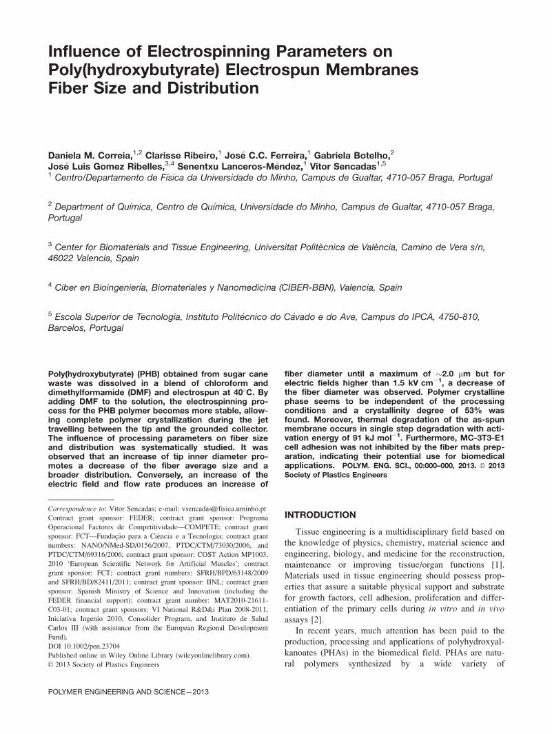
1. A histogram (Fig. 1c and d) of the fiber diameter dis-
tribution, determined from the SEM images and fiber
average size and standard deviation was obtained. The as-
spun membranes presented a fibrillar structure, without
bead formation, with a smooth surface and with randomly
oriented fibrils on the static grounded collector.
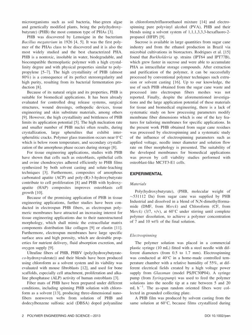
Samples obtained at several applied electric fields
between the needle tip and the ground metallic collector
showed a mean diameter that ranges between 1.31 6 0.13
mm and 2.01 6 0.17 mm (Fig. 2). An increase of the mean
fiber diameter with increasing of the applied electric field
was observed until 1.5 kV cm21. By further increasing
the applied electric field, a decrease of the mean fiber
diameter occurred (Fig. 2a) due to changes in mass flow
and jet dynamics promoted by the applied electric field
[17].
The formation of the thin fibers is mainly due to the
stretching and acceleration of the jets promoted by the
high electric field [18, 20] which in turn will result in
higher charge density on the surface of the jets, increasing
FIG. 1. PHB electrospun membranes obtained at 10/90 (10% PHB 1 90% solvent blend) with a needle
inner diameter of 0.5 mm and a flow rate of 10 mL h21 at 1 kV cm21 [(a) and (c)] and 1.75 kV cm21 [(b)
and (d)].
FIG. 2. (a) Influence of applied electric field and (b) Influence of needle inner diameter on the mean diam-
eter of the electrospun PHB fibers.
4 POLYMER ENGINEERING AND SCIENCE—2013 DOI 10.1002/pen
Page 5
jet velocity and consequently fiber stretching. In this
sense, it is generally reported that the diameter of the
fibers becomes gradually smaller with increasing the
applied electric field [21–24]. Conversely, as observed in
the present experiments and in other cases reported in the
literature [17], this result is not general since increasing
charge density within the applied electric field also affect
other processing parameters such as jet traveling time,
which has the opposite effect on the fiber diameter [25].
In order to promote the formation of independent and
smooth fibers, most of the solvent evaporation must occur
during the travel between the tip and the metallic ground
collector. Increasing electric field decreases travelling
time. Furthermore, increasing the applied electric field
often enhances jet instability, promoting multiple fiber
formation, which results in a broader distribution of the
fiber diameters [18, 22, 26].
The inner diameter of the needle also plays an impor-
tant role in the electrospun fiber size and distribution.
Typically, a small internal diameter reduces clogging and
prevents the formation of beads on the electrospun fibers
as well due to less exposure of the solution to the atmos-
phere during processing [27].
For PHB it was found that increasing needle inner
diameter is associated to a decrease of the fiber mean
diameter and size distribution becomes broader (Fig. 2b).
Literature shows contradictory results concerning the
influence of the internal needle diameter. No influence
of needle diameter on average fiber diameter for
poly(methyl methacrylate) electrospun fibers was found, but
on the other hand, some authors report that a decrease of the
needle inner diameter is associated to a reduction of the of
fiber diameter, and such behavior was attributed to the
increasing surface tension of the droplet, which results in
variations of the forces needed for jet initialization and
therefore in traveling time, influencing jet stretching and
solvent evaporation [17]. For PHB electrospun fibers, the
increase of the needle inner diameter results in a higher
droplet volume ate the needle tip during the electrospinning
and no stable Taylor cone is achieved, and several jets arise
simultaneously from the droplet, that are stretched by the
electric field giving origin to smaller and broader fiber diam-
eter (Fig. 2b). Further, the area of the droplet expose to air
increases with for higher needle diameters during processing
and as a result clogging at the tip of the needle occurred eas-
ily and electrospinning terminated automatically within a
very short of time before sufficient fiber could be produced.
Such effect was also observed Tong and Wang [28].
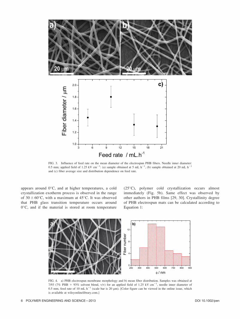
The influence of the solution feed rate on electrospun
fiber mean diameter and distribution was also analyzed
keeping constant the applied voltage (25 kV) and the nee-
dle inner diameter (0.5 mm, Fig. 3).
It is observed that increasing feed rate from 5 up to 10
mL h21 increases the mean fiber diameter, but by further
increasing flow rates a slight decrease of the mean fiber
diameter occurs (Fig. 3). On the other hand, fiber size
distribution is very similar for the samples collected at
different feed rates. It is generally expected increasing
fiber diameters and number of beads when the feed rate
increases due to the larger volume of solution that is
drawn away from the needle. This increase of volume
drawn from the needle tip will promote an increase of the
time for the solvent to evaporate and consequently more
time is needed for the polymer to crystallize, given origin
to higher fiber diameters and broader distribution as
observed for other polymer systems like PVDF [18], PLA
[26], and chitosan [25].
For PHB, it seems that the low boiling point of the CF/
DMF solvent blend (Table 1) allows a fast evaporation dur-
ing the flight time. In this situation, full solvent evaporation
occurs when the fiber reaches the grounded collector and
therefore the feed rate does not have strong influence on
fiber diameter. It is also observed that for feed rates higher
than 20 mL h21 the jet becomes instable and the fiber
reaches the ground metallic collector with some solvent
promoting the dissolution of the fibers already collected.
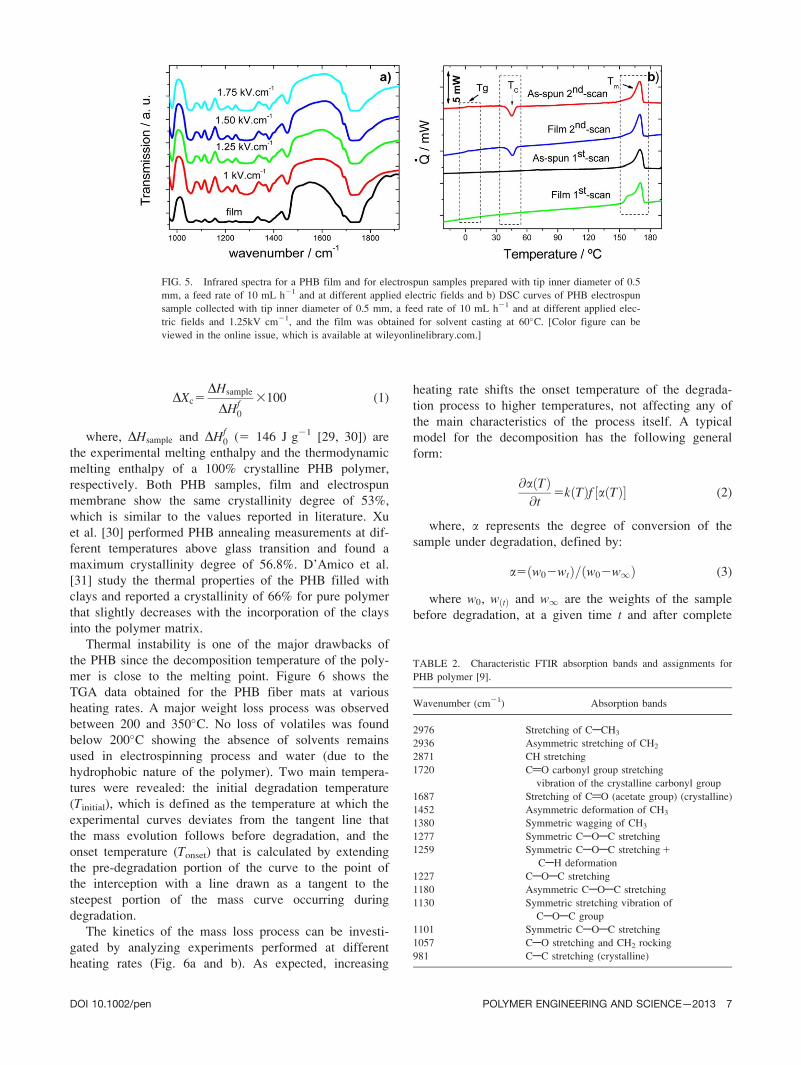
To study the influence of the polymer concentration of
the CF/DMF solution, different polymer/solvent ratios
were prepared. For an amount of 5% PHB on solvent dis-
solution, electrospinning was not feasible due to the high
conductivity of the solution that promotes sparks. Increas-
ing PHB concentration to 7% allows stable polymer elec-
trospinning. Moreover, a decrease of the fiber diameter
from 1.8 6 0.2 mm (Fig. 1) down to 530 6 140 nm was
observed and the fibers present same randomly distribu-
tion, with smooth fibers, without ribbons or beads (Fig. 4)
observed for the polymer concentration of 10% (Fig. 1).
Stability Against Processing Conditions
Fourier transform infrared spectroscopy (FTIR) was
used to monitor variations at a molecular level that might
occur due to the electrospun conditions. Figure 5 shows
the characteristic infrared spectra observed for PHB film
and for the electrospun fibers obtained at different applied
electrical fields. The overall response of the FTIR spectra
is quite similar, no vibration modes are totally suppressed
and no new modes seems to appear due to the changes in
the processing parameters (Fig. 5), that is, the structure
and the crystalline phase of the PHB remain the same,
independently of the processing conditions.
PHB absorption bands and their assignments are sum-
marized in Table 2. The results obtained showed that the
most characteristic absorption peaks are the carbonyl and
hydroxyl groups at �1720 and 3278 cm21, respectively.
Other characteristic bands for PHB polymer appear at
�1276, �1180, and �1057 cm21, which can be assigned
to the ester groups of the polymer (Fig. 5a).
Differential scanning calorimetry (DSC) normalized
thermograms (heat flow divided by sample mass and
heating rate) are shown in Fig. 5b. The first heating scan
shows a strong endothermic peak around 170�C that cor-
responds to melting. On the second scan, recorded after
cooling from the melt at 10�C min21, the glass transition
DOI 10.1002/pen POLYMER ENGINEERING AND SCIENCE—2013 5
Page 6
appears around 0�C, and at higher temperatures, a cold
crystallization exotherm process is observed in the range
of 30 6 60�C, with a maximum at 45�C. It was observed
that PHB glass transition temperature occurs around
0�C, and if the material is stored at room temperature
(25�C), polymer cold crystallization occurs almost
immediately (Fig. 5b). Same effect was observed by
other authors in PHB films [29, 30]. Crystallinity degree
of PHB electrospun mats can be calculated according to
Equation 1:
FIG. 4. a) PHB electrospun membrane morphology and b) mean fiber distribution. Samples was obtained at
7/93 (7% PHB 1 93% solvent blend, v/v) for an applied field of 1.25 kV cm21, needle inner diameter of
0.5 mm, feed rate of 10 mL h21 (scale bar is 20 mm). [Color figure can be viewed in the online issue, which
is available at wileyonlinelibrary.com.]
FIG. 3. Influence of feed rate on the mean diameter of the electrospun PHB fibers. Needle inner diameter:
0.5 mm; applied field of 1.25 kV cm21: (a) sample obtained at 5 mL h21, (b) sample obtained at 20 mL h21
and (c) fiber average size and distribution dependence on feed rate.
6 POLYMER ENGINEERING AND SCIENCE—2013 DOI 10.1002/pen
Page 7
DXc5DHsample
DHf0
3100 (1)
where, DHsample and DHf0 (5 146 J g21 [29, 30]) are
the experimental melting enthalpy and the thermodynamic
melting enthalpy of a 100% crystalline PHB polymer,
respectively. Both PHB samples, film and electrospun
membrane show the same crystallinity degree of 53%,
which is similar to the values reported in literature. Xu
et al. [30] performed PHB annealing measurements at dif-
ferent temperatures above glass transition and found a
maximum crystallinity degree of 56.8%. D’Amico et al.
[31] study the thermal properties of the PHB filled with
clays and reported a crystallinity of 66% for pure polymer
that slightly decreases with the incorporation of the clays
into the polymer matrix.
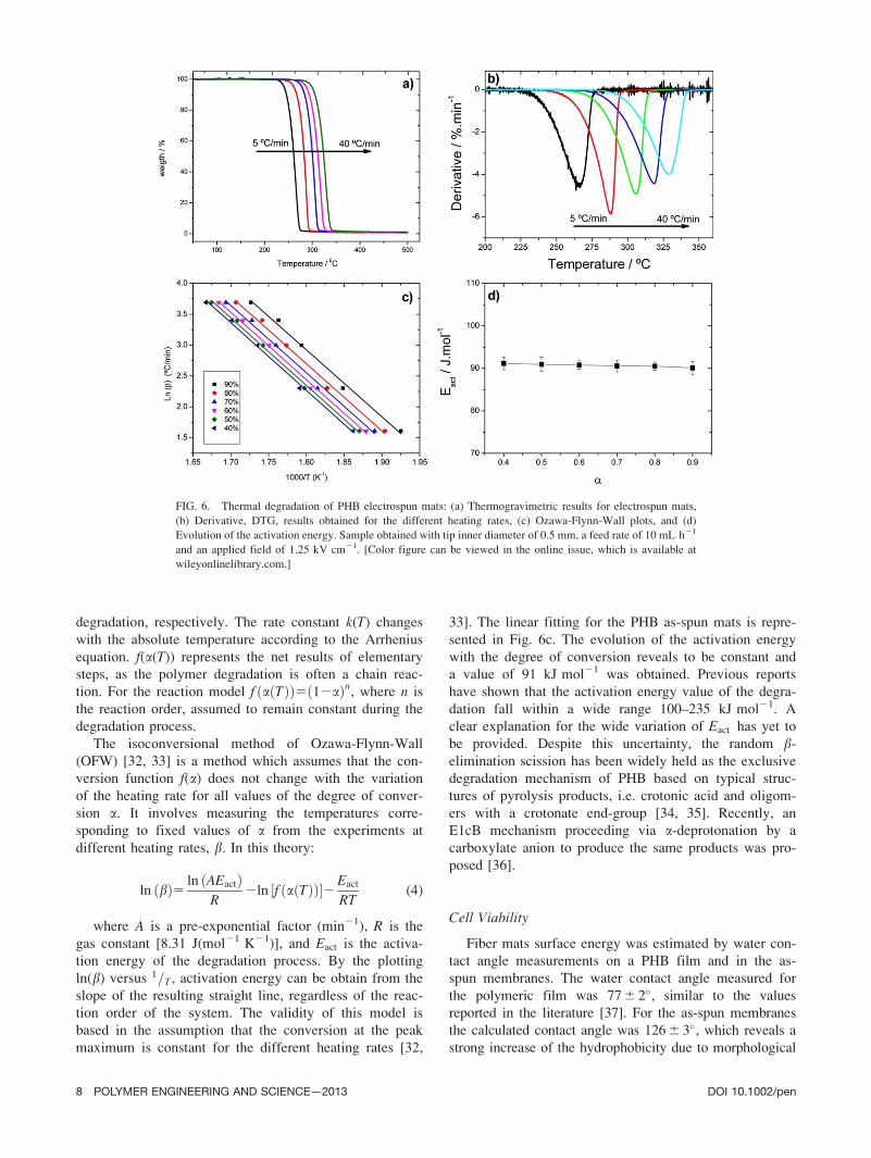
Thermal instability is one of the major drawbacks of
the PHB since the decomposition temperature of the poly-
mer is close to the melting point. Figure 6 shows the
TGA data obtained for the PHB fiber mats at various
heating rates. A major weight loss process was observed
between 200 and 350�C. No loss of volatiles was found
below 200�C showing the absence of solvents remains
used in electrospinning process and water (due to the
hydrophobic nature of the polymer). Two main tempera-
tures were revealed: the initial degradation temperature
(Tinitial), which is defined as the temperature at which the
experimental curves deviates from the tangent line that
the mass evolution follows before degradation, and the
onset temperature (Tonset) that is calculated by extending
the pre-degradation portion of the curve to the point of
the interception with a line drawn as a tangent to the
steepest portion of the mass curve occurring during
degradation.
The kinetics of the mass loss process can be investi-
gated by analyzing experiments performed at different
heating rates (Fig. 6a and b). As expected, increasing
heating rate shifts the onset temperature of the degrada-
tion process to higher temperatures, not affecting any of
the main characteristics of the process itself. A typical
model for the decomposition has the following general
form:
@a Tð Þ@t
5k Tð Þf a Tð Þ½ � (2)
where, a represents the degree of conversion of the
sample under degradation, defined by:
a5 w02wtð Þ= w02w1ð Þ (3)
where w0, w tð Þ and w1 are the weights of the sample
before degradation, at a given time t and after complete
TABLE 2. Characteristic FTIR absorption bands and assignments for
PHB polymer [9].
Wavenumber (cm21) Absorption bands
2976 Stretching of CACH3
2936 Asymmetric stretching of CH2
2871 CH stretching
1720 C@O carbonyl group stretching
vibration of the crystalline carbonyl group
1687 Stretching of C@O (acetate group) (crystalline)
1452 Asymmetric deformation of CH3
1380 Symmetric wagging of CH3
1277 Symmetric CAOAC stretching
1259 Symmetric CAOAC stretching 1
CAH deformation
1227 CAOAC stretching
1180 Asymmetric CAOAC stretching
1130 Symmetric stretching vibration of
CAOAC group
1101 Symmetric CAOAC stretching
1057 CAO stretching and CH2 rocking
981 CAC stretching (crystalline)
FIG. 5. Infrared spectra for a PHB film and for electrospun samples prepared with tip inner diameter of 0.5
mm, a feed rate of 10 mL h21 and at different applied electric fields and b) DSC curves of PHB electrospun
sample collected with tip inner diameter of 0.5 mm, a feed rate of 10 mL h21 and at different applied elec-
tric fields and 1.25kV cm21, and the film was obtained for solvent casting at 60�C. [Color figure can be
viewed in the online issue, which is available at wileyonlinelibrary.com.]
DOI 10.1002/pen POLYMER ENGINEERING AND SCIENCE—2013 7
Page 8
degradation, respectively. The rate constant k(T) changes
with the absolute temperature according to the Arrhenius
equation. f(a(T)) represents the net results of elementary
steps, as the polymer degradation is often a chain reac-
tion. For the reaction model f a Tð Þð Þ5 12að Þn, where n is
the reaction order, assumed to remain constant during the
degradation process.
The isoconversional method of Ozawa-Flynn-Wall
(OFW) [32, 33] is a method which assumes that the con-
version function f(a) does not change with the variation
of the heating rate for all values of the degree of conver-
sion a. It involves measuring the temperatures corre-
sponding to fixed values of a from the experiments at
different heating rates, b. In this theory:
ln bð Þ5 ln AEactð ÞR
2ln f a Tð Þð Þ½ �2 Eact
RT(4)
where A is a pre-exponential factor (min21), R is the
gas constant [8.31 J(mol21 K21)], and Eact is the activa-
tion energy of the degradation process. By the plotting
ln(b) versus 1T= , activation energy can be obtain from the
slope of the resulting straight line, regardless of the reac-
tion order of the system. The validity of this model is
based in the assumption that the conversion at the peak
maximum is constant for the different heating rates [32,
33]. The linear fitting for the PHB as-spun mats is repre-
sented in Fig. 6c. The evolution of the activation energy
with the degree of conversion reveals to be constant and
a value of 91 kJ mol21 was obtained. Previous reports
have shown that the activation energy value of the degra-
dation fall within a wide range 100–235 kJ mol21. A
clear explanation for the wide variation of Eact has yet to
be provided. Despite this uncertainty, the random b-
elimination scission has been widely held as the exclusive
degradation mechanism of PHB based on typical struc-
tures of pyrolysis products, i.e. crotonic acid and oligom-
ers with a crotonate end-group [34, 35]. Recently, an
E1cB mechanism proceeding via a-deprotonation by a
carboxylate anion to produce the same products was pro-
posed [36].
Cell Viability
Fiber mats surface energy was estimated by water con-
tact angle measurements on a PHB film and in the as-
spun membranes. The water contact angle measured for
the polymeric film was 77 6 2�, similar to the values
reported in the literature [37]. For the as-spun membranes
the calculated contact angle was 126 6 3�, which reveals a
strong increase of the hydrophobicity due to morphological
FIG. 6. Thermal degradation of PHB electrospun mats: (a) Thermogravimetric results for electrospun mats,
(b) Derivative, DTG, results obtained for the different heating rates, (c) Ozawa-Flynn-Wall plots, and (d)
Evolution of the activation energy. Sample obtained with tip inner diameter of 0.5 mm, a feed rate of 10 mL h21
and an applied field of 1.25 kV cm21. [Color figure can be viewed in the online issue, which is available at
wileyonlinelibrary.com.]
8 POLYMER ENGINEERING AND SCIENCE—2013 DOI 10.1002/pen
Page 9
variations. This behavior is common to other polymeric
systems obtained by electrospinning such as PLA [38].
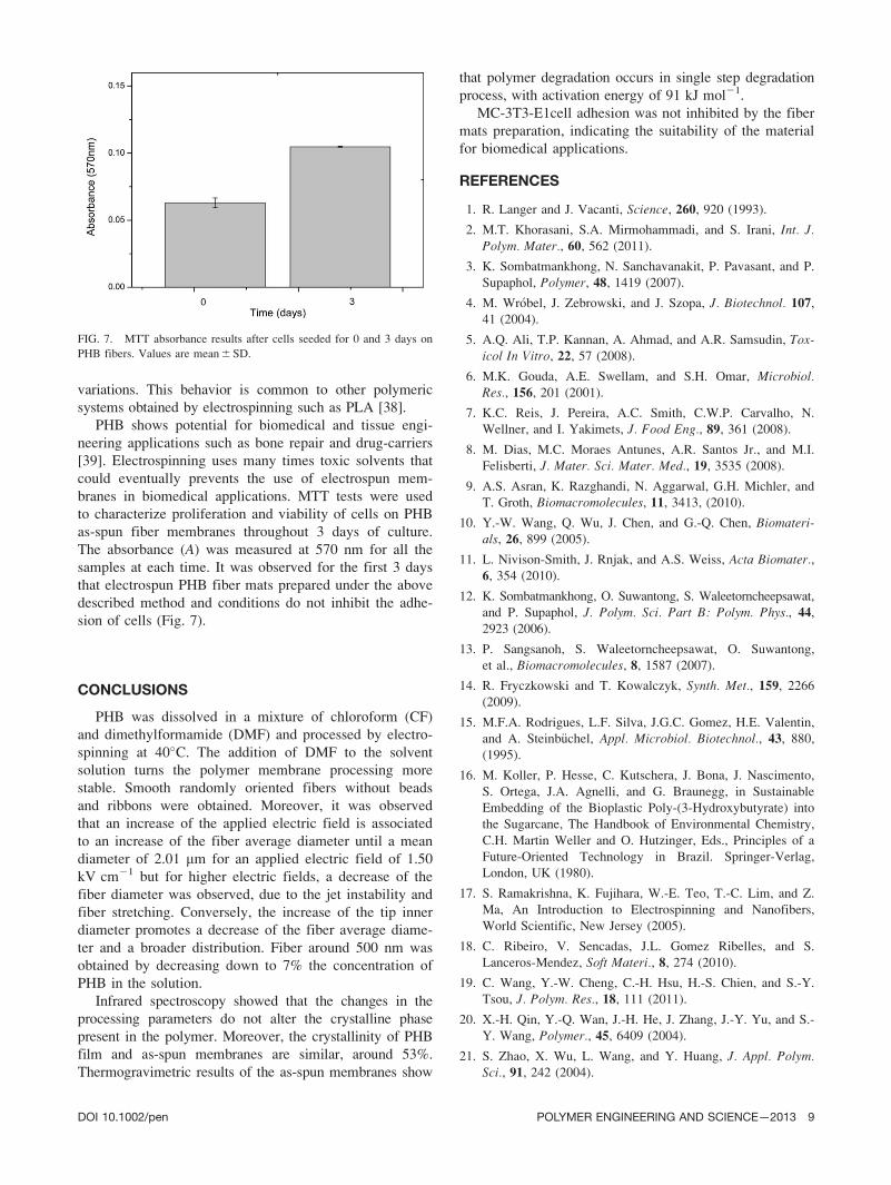
PHB shows potential for biomedical and tissue engi-
neering applications such as bone repair and drug-carriers
[39]. Electrospinning uses many times toxic solvents that
could eventually prevents the use of electrospun mem-
branes in biomedical applications. MTT tests were used
to characterize proliferation and viability of cells on PHB
as-spun fiber membranes throughout 3 days of culture.
The absorbance (A) was measured at 570 nm for all the
samples at each time. It was observed for the first 3 days
that electrospun PHB fiber mats prepared under the above
described method and conditions do not inhibit the adhe-
sion of cells (Fig. 7).
CONCLUSIONS
PHB was dissolved in a mixture of chloroform (CF)
and dimethylformamide (DMF) and processed by electro-
spinning at 40�C. The addition of DMF to the solvent
solution turns the polymer membrane processing more
stable. Smooth randomly oriented fibers without beads
and ribbons were obtained. Moreover, it was observed
that an increase of the applied electric field is associated
to an increase of the fiber average diameter until a mean
diameter of 2.01 mm for an applied electric field of 1.50
kV cm21 but for higher electric fields, a decrease of the
fiber diameter was observed, due to the jet instability and
fiber stretching. Conversely, the increase of the tip inner
diameter promotes a decrease of the fiber average diame-
ter and a broader distribution. Fiber around 500 nm was
obtained by decreasing down to 7% the concentration of
PHB in the solution.
Infrared spectroscopy showed that the changes in the
processing parameters do not alter the crystalline phase
present in the polymer. Moreover, the crystallinity of PHB
film and as-spun membranes are similar, around 53%.
Thermogravimetric results of the as-spun membranes show
that polymer degradation occurs in single step degradation
process, with activation energy of 91 kJ mol21.
MC-3T3-E1cell adhesion was not inhibited by the fiber
mats preparation, indicating the suitability of the material
for biomedical applications.
REFERENCES
1. R. Langer and J. Vacanti, Science, 260, 920 (1993).
2. M.T. Khorasani, S.A. Mirmohammadi, and S. Irani, Int. J.Polym. Mater., 60, 562 (2011).
3. K. Sombatmankhong, N. Sanchavanakit, P. Pavasant, and P.
Supaphol, Polymer, 48, 1419 (2007).
4. M. Wr�obel, J. Zebrowski, and J. Szopa, J. Biotechnol. 107,
41 (2004).
5. A.Q. Ali, T.P. Kannan, A. Ahmad, and A.R. Samsudin, Tox-icol In Vitro, 22, 57 (2008).
6. M.K. Gouda, A.E. Swellam, and S.H. Omar, Microbiol.Res., 156, 201 (2001).
7. K.C. Reis, J. Pereira, A.C. Smith, C.W.P. Carvalho, N.
Wellner, and I. Yakimets, J. Food Eng., 89, 361 (2008).
8. M. Dias, M.C. Moraes Antunes, A.R. Santos Jr., and M.I.
Felisberti, J. Mater. Sci. Mater. Med., 19, 3535 (2008).
9. A.S. Asran, K. Razghandi, N. Aggarwal, G.H. Michler, and
T. Groth, Biomacromolecules, 11, 3413, (2010).
10. Y.-W. Wang, Q. Wu, J. Chen, and G.-Q. Chen, Biomateri-als, 26, 899 (2005).
11. L. Nivison-Smith, J. Rnjak, and A.S. Weiss, Acta Biomater.,6, 354 (2010).
12. K. Sombatmankhong, O. Suwantong, S. Waleetorncheepsawat,
and P. Supaphol, J. Polym. Sci. Part B: Polym. Phys., 44,
2923 (2006).
13. P. Sangsanoh, S. Waleetorncheepsawat, O. Suwantong,
et al., Biomacromolecules, 8, 1587 (2007).
14. R. Fryczkowski and T. Kowalczyk, Synth. Met., 159, 2266
(2009).
15. M.F.A. Rodrigues, L.F. Silva, J.G.C. Gomez, H.E. Valentin,
and A. Steinb€uchel, Appl. Microbiol. Biotechnol., 43, 880,
(1995).
16. M. Koller, P. Hesse, C. Kutschera, J. Bona, J. Nascimento,
S. Ortega, J.A. Agnelli, and G. Braunegg, in Sustainable
Embedding of the Bioplastic Poly-(3-Hydroxybutyrate) into
the Sugarcane, The Handbook of Environmental Chemistry,
C.H. Martin Weller and O. Hutzinger, Eds., Principles of a
Future-Oriented Technology in Brazil. Springer-Verlag,
London, UK (1980).
17. S. Ramakrishna, K. Fujihara, W.-E. Teo, T.-C. Lim, and Z.
Ma, An Introduction to Electrospinning and Nanofibers,
World Scientific, New Jersey (2005).
18. C. Ribeiro, V. Sencadas, J.L. Gomez Ribelles, and S.
Lanceros-Mendez, Soft Materi., 8, 274 (2010).
19. C. Wang, Y.-W. Cheng, C.-H. Hsu, H.-S. Chien, and S.-Y.
Tsou, J. Polym. Res., 18, 111 (2011).
20. X.-H. Qin, Y.-Q. Wan, J.-H. He, J. Zhang, J.-Y. Yu, and S.-
Y. Wang, Polymer., 45, 6409 (2004).
21. S. Zhao, X. Wu, L. Wang, and Y. Huang, J. Appl. Polym.Sci., 91, 242 (2004).
FIG. 7. MTT absorbance results after cells seeded for 0 and 3 days on
PHB fibers. Values are mean 6 SD.
DOI 10.1002/pen POLYMER ENGINEERING AND SCIENCE—2013 9
Page 10
22. K. Gao, X. Hu, C. Dai, and T. Yi, Mater. Sci. Eng. B, 131,
100 (2006).
23. M.M. Demir, I. Yilgor, E. Yilgor, and B. Erman, Polymer,
43, 3303 (2002).
24. S. Megelski, J.S. Stephens, D.B. Chase, and J.F. Rabolt,
Macromolecules, 35, 8456 (2002).
25. V. Sencadas, D.M. Correia, A. Areias, G. Botelho, A.F.
Fonseca, I.C. Neves, J.L. Gomez Ribelles, and S. Lanceros-
M�endez, Carbohydr. Polym., 87, 1295 (2012).
26. C. Ribeiro, V. Sencadas, C. Miguel Costa, J.L. Gomez
Ribelles, and S. Lanceros-Mendez, Sci. Technol. Adv.Mater., 12 (2011).
27. X.M. Mo, C.Y. Xu, M. Kotaki, and S. Ramakrishna,
Biomaterials, 25, 1883 (2004).
28. H.-W. Tong and M. Wang, J. Macromol. Sci. Part B, 50,
1535 (2011).
29. J. Kemnitzer, R. Gross, S. McCarthy, J. Liggat, D. Blundell,
and M. Cox, J. Polym. Environ., 3, 37 (1995).
30. S. Xu, R. Luo, L. Wu, K. Xu, and G.-Q. Chen, J. Appl.Polym. Sci., 102, 3782 (2006).
31. D.A. D’Amico, L.B. Manfredi, and V.P. Cyras, J. Appl.Polym. Sci., 123, 200 (2012).
32. J.H. Flynn and L.A. Wall, J. Polym. Sci. Part B: Polym.Lett., 4, 323 (1966).
33. T. Ozawa, Bull. Chem. Soc. Japan, 38, 1881 (1965).
34. H. Morikawa and R.H. Marchessault, Canadian J. Chem.,59, 2306 (1981).
35. A. Ballistreri, D. Garozzo, M. Giuffrida, G. Impallomeni,
and G. Montaudo, J. Anal. Appl. Pyrol., 16, 239 (1989).
36. M. Kawalec, G. Adamus, P. Kurcok, M. Kowalczuk, I.
Foltran, and M.L., Biomacromolecules, 8, 1053 (2007).
37. D.M. Zhang, F.Z. Cui, Z.S. Luo, Y.B. Lin, K. Zhao, and
G.Q. Chen, Surf. Coat. Technol., 131, 350 (2000).
38. A.C. Areias, C. Ribeiro, V. Sencadas, N. Garcia-Giralt, A.
Diez-Perez, J.L. Gomez Ribelles, and S. Lanceros-M�endez,
Soft Matter, 8, 5818 (2012).
39. G.-Q. Chen and Q. Wu, Biomaterials, 26, 6565 (2005).
10 POLYMER ENGINEERING AND SCIENCE—2013 DOI 10.1002/pen