Filipovi}, I., et al.: Influence of Geometric and Hydro-Dynamic Parameters of … THERMAL SCIENCE, Year 2011, Vol. 15, No. 4, pp. 1095-1109 1095 INFLUENCE OF GEOMETRIC AND HYDRO-DYNAMIC PARAMETERS OF INJECTOR ON CALCULATION OF SPRAY CHARACTERISTICS OF DIESEL ENGINES by Ivan M. FILIPOVI] * , Boran D. PIKULA, and Dževad [. BIBI] Department for IC Engines and Vehicles, Faculty of Mechanical Engineering, University of Sarajevo, Sarajevo, Bosnia and Herzegovina Original scientific paper UDC: 621.43.038 DOI: 10.2298/TSCI100903046F The main role in air/fuel mixture formation at the IC Diesel engines has the energy in- troduced by fuel into the IC engine that is the characteristics of spraying fuel into the combustion chamber. The characteristic can be defined by the spray length, the spray cone angle, and the physical and chemical structure of fuel spray by different sections. Having in mind very complex experimental set-ups for researching in this field, the men- tioned characteristics are mostly analyzed by calculations. There are two methods in the literature. The first based on use of the semi-empirical expressions (correlations) and the second, the calculations of spray characteristics by use of very complex mathematical methods. The second method is dominant in the modern literature. The main disadvantage of the calculation methods is a correct definition of real state at the end of the nozzle orifice (real boundary conditions). The majority of the researchers in this field use most frequently the coefficient of total losses inside the injector. This coefficient depends on injector design, as well as depends on the level of fuel energy and fuel energy transformation along the injector. Having in mind the importance of the real boundary conditions, the complex methods for calculation of the fuel spray characteris- tics should have the calculation of fuel flows inside the injector and the calculation of spray characteristics together. This approach is a very complex numerical problem and there are no existing computer programs with satisfactory calculation results. Analysis of spray characteristics by use of the semi-empirical expressions (correlations) is presented in this paper. The special attention is dedicated to the analysis of the con- stant in the semi-empirical expressions and influence parameters on this constant. Also, the method for definition of realistic boundary condition at the end of the nozzle orifice is presented in the paper. By use of this method completely avoid a use of the coefficient of total losses inside the injector. At the same time, semi-empirical expressions have the universal constant that does not depend on the injector design. Keywords: injector, spray, diesel fuel, loss coefficient, modeling Introduction The combustion process in the direct fuel injected Diesel engines (DI) mostly depends from quality of the air/fuel mixture formation. The air/fuel mixture process can be accepted and analyzed by total energy of the air and the fuel introduced into the DI. At DI, *nCorresponding author; e-mail: [email protected]
Transcript
Filipovi}, I., et al.: Influence of Geometric and Hydro-Dynamic Parameters of … THERMAL SCIENCE, Year 2011, Vol. 15, No. 4, pp. 1095-1109 1095
INFLUENCE OF GEOMETRIC AND HYDRO-DYNAMIC PARAMETERS
OF INJECTOR ON CALCULATION OF SPRAY CHARACTERISTICS
OF DIESEL ENGINES
by
Ivan M. FILIPOVI] *
, Boran D. PIKULA, and Dževad [. BIBI]
Department for IC Engines and Vehicles, Faculty of Mechanical Engineering, University of Sarajevo, Sarajevo, Bosnia and Herzegovina
Original scientific paper UDC: 621.43.038
DOI: 10.2298/TSCI100903046F
The main role in air/fuel mixture formation at the IC Diesel engines has the energy in-troduced by fuel into the IC engine that is the characteristics of spraying fuel into the combustion chamber. The characteristic can be defined by the spray length, the spray cone angle, and the physical and chemical structure of fuel spray by different sections. Having in mind very complex experimental set-ups for researching in this field, the men-tioned characteristics are mostly analyzed by calculations. There are two methods in the literature. The first based on use of the semi-empirical expressions (correlations) and the second, the calculations of spray characteristics by use of very complex mathematical methods. The second method is dominant in the modern literature. The main disadvantage of the calculation methods is a correct definition of real state at the end of the nozzle orifice (real boundary conditions). The majority of the researchers in this field use most frequently the coefficient of total losses inside the injector. This coefficient depends on injector design, as well as depends on the level of fuel energy and fuel energy transformation along the injector. Having in mind the importance of the real boundary conditions, the complex methods for calculation of the fuel spray characteris-tics should have the calculation of fuel flows inside the injector and the calculation of spray characteristics together. This approach is a very complex numerical problem and there are no existing computer programs with satisfactory calculation results. Analysis of spray characteristics by use of the semi-empirical expressions (correlations) is presented in this paper. The special attention is dedicated to the analysis of the con-stant in the semi-empirical expressions and influence parameters on this constant. Also, the method for definition of realistic boundary condition at the end of the nozzle orifice is presented in the paper. By use of this method completely avoid a use of the coefficient of total losses inside the injector. At the same time, semi-empirical expressions have the universal constant that does not depend on the injector design.
Keywords: injector, spray, diesel fuel, loss coefficient, modeling
Introduction
The combustion process in the direct fuel injected Diesel engines (DI) mostly
depends from quality of the air/fuel mixture formation. The air/fuel mixture process can be
accepted and analyzed by total energy of the air and the fuel introduced into the DI. At DI,
Filipovi}, I., et al.: Influence of Geometric and Hydro-Dynamic Parameters of … 1096 THERMAL SCIENCE, Year 2011, Vol. 15, No. 4, pp. 1095-1109
especially at DI with greater displacement, the most important role is played by the fuel
energy. In all realistic conditions, the fuel energy can be manifested through spray
characteristics. The spray characteristics, in the ambient where the spray develops, can be
expressed in the following form:
the spray dimensions like: the spray length, the spray cone angle, parameters after spray
impact with wall, etc. as a function of the time, and
the physical and chemical spray structure, where the physical spray structure is determi-
nate mostly by mean Sauter diameter of droplets in different spray cross-sections. On the
other hand, a chemical structure in different cross-sections of the spray and as a function
of the time is interesting in case of multi components fuels, like diesel fuel. The basic
principle in case of these fuels is that the heavy component of CXHY are concentrated in
the middle of the spray and have a better penetration, while lighter CXHY are located on
the periphery of the spray and have a better vaporization.
In the air/fuel mixture formation analysis, the spray shape characteristics (spray
dimensions) are mentioned mostly. Based on these characteristics, one can make conclusions
regarding the air/fuel mixture homogeneity in the whole ambient of the combustion chamber,
the cross overlying next sprays, the influence of the combustion chamber walls, etc. In this
context, the majority of the researchers analyzes diesel fuel sprays and recommends influence
parameters for spray dimensions and shapes. Generally, the different spray shapes are mostly
presented in the fig. 1, where the free shape fuel spray, injected into free ambient without
walls, is presented in fig. 1(a).
Figure 1. The characteristic spray shapes in different ambient
Filipovi}, I., et al.: Influence of Geometric and Hydro-Dynamic Parameters of … THERMAL SCIENCE, Year 2011, Vol. 15, No. 4, pp. 1095-1109 1097
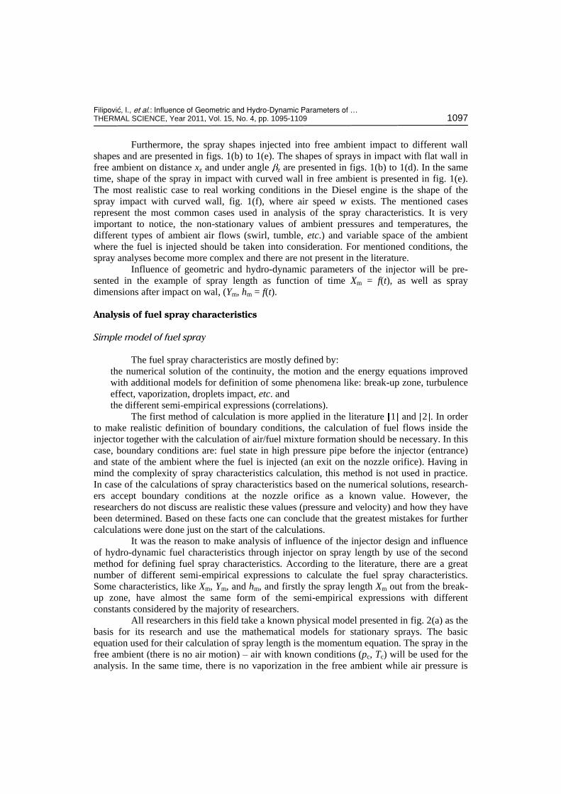
Furthermore, the spray shapes injected into free ambient impact to different wall
shapes and are presented in figs. 1(b) to 1(e). The shapes of sprays in impact with flat wall in
free ambient on distance xz and under angle z are presented in figs. 1(b) to 1(d). In the same
time, shape of the spray in impact with curved wall in free ambient is presented in fig. 1(e).
The most realistic case to real working conditions in the Diesel engine is the shape of the
spray impact with curved wall, fig. 1(f), where air speed w exists. The mentioned cases
represent the most common cases used in analysis of the spray characteristics. It is very
important to notice, the non-stationary values of ambient pressures and temperatures, the
different types of ambient air flows (swirl, tumble, etc.) and variable space of the ambient
where the fuel is injected should be taken into consideration. For mentioned conditions, the
spray analyses become more complex and there are not present in the literature.
Influence of geometric and hydro-dynamic parameters of the injector will be pre-
sented in the example of spray length as function of time Xm = f(t), as well as spray
dimensions after impact on wal, (Ym, hm = f(t).
Analysis of fuel spray characteristics
Simple model of fuel spray
The fuel spray characteristics are mostly defined by:
the numerical solution of the continuity, the motion and the energy equations improved
with additional models for definition of some phenomena like: break-up zone, turbulence
effect, vaporization, droplets impact, etc. and
the different semi-empirical expressions (correlations).
The first method of calculation is more applied in the literature 1 and 2 . In order
to make realistic definition of boundary conditions, the calculation of fuel flows inside the
injector together with the calculation of air/fuel mixture formation should be necessary. In this
case, boundary conditions are: fuel state in high pressure pipe before the injector (entrance)
and state of the ambient where the fuel is injected (an exit on the nozzle orifice). Having in
mind the complexity of spray characteristics calculation, this method is not used in practice.
In case of the calculations of spray characteristics based on the numerical solutions, research-
ers accept boundary conditions at the nozzle orifice as a known value. However, the
researchers do not discuss are realistic these values (pressure and velocity) and how they have
been determined. Based on these facts one can conclude that the greatest mistakes for further
calculations were done just on the start of the calculations.
It was the reason to make analysis of influence of the injector design and influence
of hydro-dynamic fuel characteristics through injector on spray length by use of the second
method for defining fuel spray characteristics. According to the literature, there are a great
number of different semi-empirical expressions to calculate the fuel spray characteristics.
Some characteristics, like Xm, Ym, and hm, and firstly the spray length Xm out from the break-
up zone, have almost the same form of the semi-empirical expressions with different
constants considered by the majority of researchers.
All researchers in this field take a known physical model presented in fig. 2(a) as the
basis for its research and use the mathematical models for stationary sprays. The basic
equation used for their calculation of spray length is the momentum equation. The spray in the
free ambient (there is no air motion) – air with known conditions (pc, Tc) will be used for the
analysis. In the same time, there is no vaporization in the free ambient while air pressure is
Filipovi}, I., et al.: Influence of Geometric and Hydro-Dynamic Parameters of … 1098 THERMAL SCIENCE, Year 2011, Vol. 15, No. 4, pp. 1095-1109
equal to the atmosphere pressure. Drag force due to motion of fuel spray in the free ambient is
taken in to consideration, as well. Based on the knowledge of the fluid mechanics and based
on momentum of fluid flows in the characteristic cross-sections over the reasonable length,
the simple mathematical model for calculation of the spray length can be developed.
Figure 2. Physical models of free spray (a) and spray with wall impact (b) in free ambient
Based on the physical model presented in fig. 2(a), the mathematical model between
cross-section I-I and II-II can be expressed by use of momentum of fluid flows as:
I-I II-IIK K (1)
Expression for the momentum of fluid flow in cross-section I-I can be written as:
22 2 2b
I-I L b b b4 2
dK v c d p (2)
where the velocity at the exit from the injector orifice is calculated by Bernoulli equations for
referent locations: before the injector, cross-section A-A, fig. 3(a) and the ambient conditions
(pc, Tc), like:
b b
2
L
pv c (3)
Pressure before the injector is calculated as the average value of the pressure at the
end of the high pressure pipe during fuel injection process. Some authors calculate the
average value of this pressure for the first 0.5 ms of injection duration [3].
Expression for momentum of the fluid flow, without drag of spray motion, in the
cross-section II-II can be written as:
2 2 2
II-II m m max. 10
2 d 2R
K v r r v R (4)
where 1 2
1 0( ) df .
Filipovi}, I., et al.: Influence of Geometric and Hydro-Dynamic Parameters of … THERMAL SCIENCE, Year 2011, Vol. 15, No. 4, pp. 1095-1109 1099
For this analysis one assumption is adopted. The velocity profile (v) in the spray, out
from potential core of the spray, has the following function v = vmax.f( ), where = r/R. The
dimensionless function of the air/fuel mixture velocity profile f( ) in different cross-sections
mostly response to the Gauss error function. Other functions like f( ) = (1 – 3/2
)2 presented
in 4 and 5 , or f( ) = (1 – 2) presented in 6 are used also for analysis. However, taking
the drag of spray motion into consideration, which is expressed by the coefficient cm, the final
expression for the momentum in the cross-section II-II has the form:
2 2 2 2 2 2
II-II 1 m max. m 1 m max. 1 m max.
12 2 2 1
2 2
mcK v R c v R v R (5)
Assuming that spray width is proportional to spray length [7], in arbitrary section R
= c1Xm, as well as the local fuel density is calculated as:
12
L c max.0 L
zLm 1
2m max.
0
2 ( )d
2 ( )d
Lmm R v f
m m
R v fV
(6)
It can be assumed that, out of the spray potential core, rm rc and the eqs (1), (2),
and (5) offer the following relation:
2 2 2 2 2mb b 1 c max. 1 m2 1
2 2
cc d p v c X (7)
i. e.
0.51 0.5b 1 1
max. b0.5c mm
1 1
21
2
c c pv d
Xc
(8)
Based on the fact that the maximum velocity (vmax.) can be expressed as vmax. =
= dXm/dt, the spray length can be calculated from eq. (8) as:
0.5
0.25 0.251 0.50.5 0.5 0.5 0.5b 1 1
m b 1 b0.5c cm1
2
c c p pX d t C d t
c (9)
where C1 is the constant defined as:
0.5 0.5 0.25b 1 1
1 0.25
m12
c cC
c
(10)
By using the physical model of spray impact in to the wall, fig. 2(b), with assuming
ome simplifies like in the previous model, the characteristic spray parameters after impact
into wall (Ym, hm) can be defined. For a simply analysis, the equation of continuity for control
Filipovi}, I., et al.: Influence of Geometric and Hydro-Dynamic Parameters of … 1100 THERMAL SCIENCE, Year 2011, Vol. 15, No. 4, pp. 1095-1109
volume bordered by surfaces AB and A'B', and envelope A-A' – B-B' was used. The equation
has the form:
c max. max 1 w0 0w w
2 d 2 dw wr z
c
y zv f y y u f r z
r z (11)
where the velocity profile along the wall is assumed as u = umax.f1(z/zw) and f1 is the
mathematical function that represent the shape of realistic velocity profile in this part of the
spray approximation. Assuming that the nozzle orifice diameter, marked in fig. 2(b), is
significantly smaller regarding other geometrical dimensions, the following simple trigono-
metry relations can be written:
w
tg tg tg;
1 tg tg 1 tg tg
cos ; tg ; tg
z zw
x xz r
r s z r h r
(12)
By use of eqs. (11) and (12) the velocity profile of spray (u), near the wall, can be
defined, as well as the location of the co-ordinate s and the spray dimensions Ym = r and hm =
h as function of time. After detail analysis of the spray dimensions Ym and hm one can make
conclusion that the influenced parameters for these characteristics are the constant cb, the
spray drag coefficient cm, the functions of velocity profiles f(r/R) and f1(z/h), the spray angle
2 and the angle , the pressure difference p, the nozzle orifice diameter db, and the time (t –
tz), where the tz is the impact time. The intensity is different to the intensity expressed in the
eq. (9). Similar models for spray characteristics can be developed in case of air speed
presence or in case of the spray with variable ambient conditions (pc, Tc) with fuel
vaporization.
In further analysis, the attention will be dedicated to the spray characteristics during
injection into the free ambient and partly to fuel spray characteristics after impact into the
wall.
Fuel spray characteristics defined by correlation expressions
Spray length during injection into the free ambient without air speed is calculated by
use of semi-empirical (correlation) expressions based on expression (9). There are several
correlation expressions in the literature where the different values have only the constant C1.
Values for the constant C1 can be: C1 = 3.01 as presented in 8 , C1 = 3.8 as presented in 6
and finally C1 = 3.9 as presented in 6 . The spray characteristics after impact on the wall can be defined the similar way.
According to the literature, the following expressions can be found:
31 2
5 64
m 2
m 3
( )
( )
aa ac z
a aac z
Y C p t t
h C p t t (13)
The following parameters exist in aforementioned expressions (9) and (13): the fuel
pressure difference ( p), the density of air ( c), nozzle orifice diameter (db), and constants C1,
C2, and C3. These constants contain the constant cb which represents the injector loss
coefficient. Analyzing the expression (9) for the spray length during injection into the free
ambient and the constant C1, one can easily see a significant dissipation of this constant in
Filipovi}, I., et al.: Influence of Geometric and Hydro-Dynamic Parameters of … THERMAL SCIENCE, Year 2011, Vol. 15, No. 4, pp. 1095-1109 1101
range, according to the literature, from 2.95 to 3.9. By using expression (10) and making an
analysis of every single value like cb, cm, c1, and 1, it is obvious that constants cm, c1, and j1
have almost the same values. In the same time, the constant cb, at the same fuel pressure
before the injector (pA) and the same nozzle orifice diameter (db), can have different values
depending on injector design. This leads to the conclusion that the main goal for different
values of the constant C1 is the injector design, what is the topic for further analysis.
Results of research for known injector
Model for calculation of hydro-dynamics characteristics
The previous analysis leads to the conclusion that fuel velocity on the nozzle orifice
exits (vb), expressed by eq. (3), and it is the most important parameter for definition of initial
and boundary conditions for spray development. Having in mind the fact that two parameters
were used to define value of fuel velocities (vb) as:
the fuel pressure difference ( p), defined by the fuel pressure before the injector (pA) on
the location the easiest for measuring and by the pressure of the ambient (pc), and
the coefficient (cb) that takes into account all losses inside the injector (friction, minor
loss, fuel contraction),
most researchers based their researching on the measurement of the fuel pressure before the
injector (pA), making average value (pAsr) and for known ambient pressure (pc), calculate the
fuel pressure difference p = pAsr – pc. In the same time, the literature was used for adopting
the injector loss coefficient (cb). Taking into the consideration the different injector designs
(some examples are shown in fig. 3), as well as the different fuel pressures before the injector,
i. e. fuel velocities inside the injector the coefficient cb can obviously have significantly
different values. These different values mostly influence the constant C1, as well as the
constants C2 and C3 in many semi-empirical expressions. Also, it is very important to notice
fuel properties, especially viscosity that can influence on the coefficient cb. This fact is
especially important in case of use of different fuels, like biodiesel, blends, etc. Further
analysis will be directed to total losses in the injector, from cross-section A-A to the cross-
-section I-I, fig. 3(a), i. e. the coefficient of total losses through injector (cb).
By using the eq. (3) and with known fuel pressure in the cross-sections A-A and I-I
(fig. 3), current value of the loss coefficient *bc and the mean value of the loss coefficient can
be written in the form:
Isr c * I cb b
Asr c A c
;p p p p
c cp p p p
(14)
adopting the fact that ambient pressure pc = const. and ignoring the losses structure through
injector. The pressure pI cannot be measured directly and it’s measuring, indirectly from
injection rate measuring, is very complex. For this reason, the calculation of hydro-dynamics
characteristics inside the injector is used and definition of the injector loss coefficient is based
on this calculation. The structure of losses the best can be seen in form of Bernoulli equation
between cross-section A-A and I-I, fig. 3(a):
22 22LL b LL A
A I2 2 2 2
j ij i
j i
vv vvp p (15)
Filipovi}, I., et al.: Influence of Geometric and Hydro-Dynamic Parameters of … 1102 THERMAL SCIENCE, Year 2011, Vol. 15, No. 4, pp. 1095-1109
where all minor losses, all friction
losses of the hydro-dynamics cha-
racteristics, at first velocities vi and
vj, should be known in different
cross-sections.
Solving the hydro-dynamics characteristics of fuel inside the injector, according to
the state-of-the-art modeling in this field, should be combination of dimensionless and 1-D
mathematical models. For this analysis, one conventional injector, shown in fig. 3(a) is taken
as an example. The injector is the Bosch manufactured injector which consists from an
injector holder of KDAL 80S20/129 type and an injector body of DLL 25S834 type, with
only one nozzle orifice (diameter db = 0.68 mm and length lb = 2 mm). More information
regarding the injector can be found in 9 . The physical model of used injector, convenient for
dimensionless and 1-D model, consisting of pipes, spaces with constant and changeable
volumes, thin wall orifices with constant and variable flow cross-sections (P), combined with
the dynamic model of needle movement is presented in fig. 4.
A detail review of characteristics of injector physical model is presented in 9 .
The basic equations for fuel flows calculations are:
(a) for the pipes with dimensions length Li and diameter di
Figure 3. Different injectors design
(a),(b) – conventional injectors with hydraulic control of needle lift, (c) – injector with piezoelectric actuator with electronic control of needle lift
Figure 4. Physical model of the injector presented in fig. 3(a)
Filipovi}, I., et al.: Influence of Geometric and Hydro-Dynamic Parameters of … THERMAL SCIENCE, Year 2011, Vol. 15, No. 4, pp. 1095-1109 1103
continuity equation
2 0
p va
t x (16)
momentum equation
1
02
iv vv p
t x d (17)
(b) for volumes (Vj), a continuity equation is used in the form:
1
d
d
kmj
mm
V pQ
E t (18)
The solutions of eqs. (16) and (17) for 1-D isentropic fluid flows in pipes can be
found by use of method of characteristics. At the same time, it has been necessary to solve
continuity eq. (18) for volumes by setting numerical method convenient for coupling with
method of characteristics. The principles for solving the mentioned equations in case of
different combinations of pipes and volumes, by use of the Newton-Raphson numerical
method, as well as the thin wall orifices are presented in 9 and 10 . The coefficients of
friction losses in eq. (17) and minor losses, expressed by Qm in eq. (18) are taken from the
11 and 12 . The equation of the needle dynamic motion is expressed in the form:
2
ii i i i2
dd
dd
ihhm k c h F
tt (19)
For this purpose eq. (19) is assumed as a linear non-homogenous differential
equation of second order. Equation (19) has transformed into two differential equations of
first order which solution have been found by the common fourth-order Runge-Kutta numeri-
cal method.
In brief presented physical and mathematical models with appropriate numerical
solutions have been verified by the experimental results. The experiments are original and
done in Laboratory for IC Engines at Mechanical Engineering Faculty, University of Maribor,
Slovenia. The piezoelectric sensor of KISTLER manufacturer of 6227 type, with mea-
surement range of 0-2000 bar in wide temperature range –50 ºC up to 200 ºC and sensitivity
2.5 pC/bar has been used for measurement of fuel pressure at the end of the high pressure pipe
pA immediately before the injector. The needle lift has been measured by inductive sensor AP
5,5/1,0, while the pressure at the nozzle orifice exit pI has been calculated from the pressure
obtained by piezoelectric sensor of KISTLER manufacturer, of 7031 type, used for definition
of the injection rate (law).
The examples of calculated and measured values of the fuel pressures and the needle
lift, for adopted injector at the full load and speed regime of the high pressure pump speed at
1100 min.–1
, are shown in fig. 5.
The calculation results of the characteristic parameters show there are no cavitation
in the fuel injection system that is confirmed by the experiments. Also, the cavitation
phenomena did not exist in injector nozzle that is analyzed in computational fluid dynamics
software by AVL Fire and shown in 9 . A similar conclusion can be obtained by the analysis
of the results presented in 13 .
Filipovi}, I., et al.: Influence of Geometric and Hydro-Dynamic Parameters of … 1104 THERMAL SCIENCE, Year 2011, Vol. 15, No. 4, pp. 1095-1109
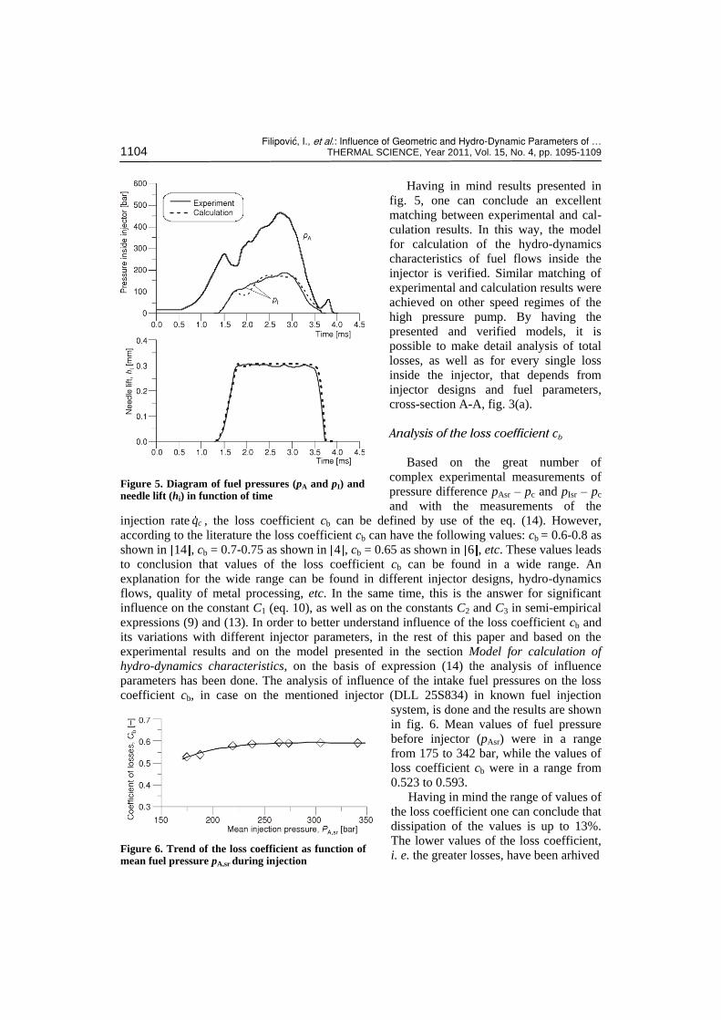
Having in mind results presented in
fig. 5, one can conclude an excellent
matching between experimental and cal-
culation results. In this way, the model
for calculation of the hydro-dynamics
characteristics of fuel flows inside the
injector is verified. Similar matching of
experimental and calculation results were
achieved on other speed regimes of the
high pressure pump. By having the
presented and verified models, it is
possible to make detail analysis of total
losses, as well as for every single loss
inside the injector, that depends from
injector designs and fuel parameters,
cross-section A-A, fig. 3(a).
Analysis of the loss coefficient cb
Based on the great number of
complex experimental measurements of
pressure difference pAsr – pc and pIsr – pc
and with the measurements of the
injection rate cq , the loss coefficient cb can be defined by use of the eq. (14). However,
according to the literature the loss coefficient cb can have the following values: cb = 0.6-0.8 as
shown in 14 , cb = 0.7-0.75 as shown in 4 , cb = 0.65 as shown in 6 , etc. These values leads
to conclusion that values of the loss coefficient cb can be found in a wide range. An
explanation for the wide range can be found in different injector designs, hydro-dynamics
flows, quality of metal processing, etc. In the same time, this is the answer for significant
influence on the constant C1 (eq. 10), as well as on the constants C2 and C3 in semi-empirical
expressions (9) and (13). In order to better understand influence of the loss coefficient cb and
its variations with different injector parameters, in the rest of this paper and based on the
experimental results and on the model presented in the section Model for calculation of
hydro-dynamics characteristics, on the basis of expression (14) the analysis of influence
parameters has been done. The analysis of influence of the intake fuel pressures on the loss
coefficient cb, in case on the mentioned injector (DLL 25S834) in known fuel injection
system, is done and the results are shown
in fig. 6. Mean values of fuel pressure
before injector (pAsr) were in a range
from 175 to 342 bar, while the values of
loss coefficient cb were in a range from
0.523 to 0.593.
Having in mind the range of values of
the loss coefficient one can conclude that
dissipation of the values is up to 13%.
The lower values of the loss coefficient,
i. e. the greater losses, have been arhived
Figure 5. Diagram of fuel pressures (pA and pI) and needle lift (hi) in function of time
Figure 6. Trend of the loss coefficient as function of mean fuel pressure pA,sr during injection
Filipovi}, I., et al.: Influence of Geometric and Hydro-Dynamic Parameters of … THERMAL SCIENCE, Year 2011, Vol. 15, No. 4, pp. 1095-1109 1105
in case of the lower mean fuel pressure
(pAsr) before the injector. Although lower
values of mean fuel pressures before the
injector mean lower fuel velocities, the
main reason for this trend is not full
needle lift. The presented results are
related to the average values of loss
coefficient cb during injection. It is very
interesting to make analysis of the current
value of loss coefficient *bc , during
injection, as well. The example of curves
that show the trend of current values of
the loss coefficient for two different engine speeds (n = 700 min.–1
and n = 1100 min.–1
) are
presented in the fig. 7. These variations of current values of the loss coefficient are more
expressed with different design solutions on the injectors.
Besides the general trends of the loss coefficient, the short analysis of influence of
different cross-sections inside the injector has been done. This analysis takes into the
consideration the locations of:
the filter inside the injector, and
the needle seat.
The original design of the filter flow
area in the injector is 2.58 mm2. During
exploitation, with presence of dirt, chang-
ing a filter temperature and flow contrac-
tions, the flow area can be changeable.
Having in mind these situations, the
analysis has been done in case of
different flow areas in the filter, from
0.785 mm2 to 3.1 mm
2. Results with val-
ues of the loss coefficient cb in case of the
max of speed regime (n = 1100 min.–1
) are
presented in fig. 8. The arrow in fig. 8
represents the original flow area of the
filter inside the injector.
Since the values of the loss coefficient
cb are in the range from 0.561 to 0.595 one
makes conclusion that injector filter design
can have a significant influence on the loss
coefficient, almost up to the 6% on one
speed regime. In the same time, it is very
easy to see that filter flow area has the
optimal value (the minimum losses) be-
cause further increasing of the filter flow
area keeps constant value of the loss
coefficient.
The second parameter which has an
influence on the loss coefficient is the
Figure 7. Trend of the current value of the loss coefficient *
bc during injection
Figure 8. Trend of the loss coefficient cb as function of the filter flow area
Figure 9. Influence of needle cone angle at needle seat (α) on the loss coefficient cb
Filipovi}, I., et al.: Influence of Geometric and Hydro-Dynamic Parameters of … 1106 THERMAL SCIENCE, Year 2011, Vol. 15, No. 4, pp. 1095-1109
location of the needle seat. In order to make an analysis, the different needle cone angles
have been used, as it shown in fig. 9. The characteristic results (values are in range from 0.585
to 0.608) are presented also in fig. 9, where the arrow represents the original needle cone
angle. It is interesting to notice that increase of needle cone angle 59.3 will reduce the
loss coefficient. On the other side, decreasing of needle cone angle does not have any
influence on the loss coefficient. The mentioned decreasing of needle cone angle can produce
additional wearing of needle seat. Since the needle cone angle is important for flow losses
from one side, as well as for wearing of the needle seat from the other side, it is very hard to
find the optimal solution and always presents a compromise. The original needle cone angle
has value = 59.72 .
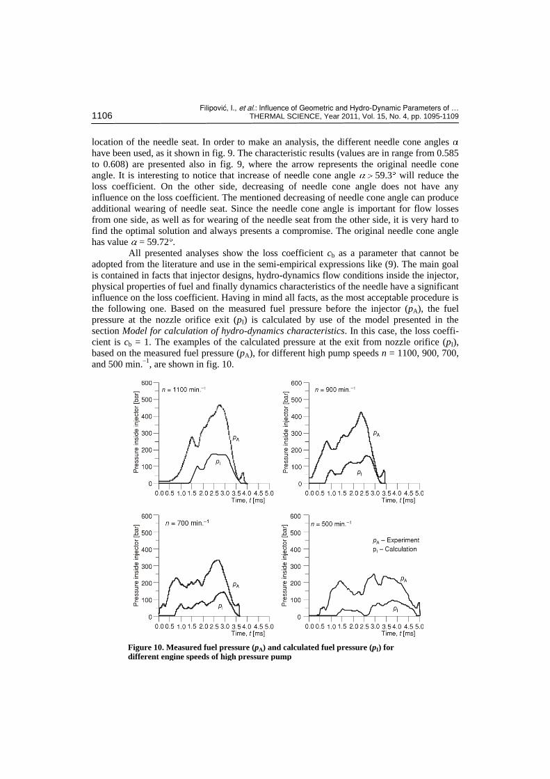
All presented analyses show the loss coefficient cb as a parameter that cannot be
adopted from the literature and use in the semi-empirical expressions like (9). The main goal
is contained in facts that injector designs, hydro-dynamics flow conditions inside the injector,
physical properties of fuel and finally dynamics characteristics of the needle have a significant
influence on the loss coefficient. Having in mind all facts, as the most acceptable procedure is
the following one. Based on the measured fuel pressure before the injector (pA), the fuel
pressure at the nozzle orifice exit (pI) is calculated by use of the model presented in the
section Model for calculation of hydro-dynamics characteristics. In this case, the loss coeffi-
cient is cb = 1. The examples of the calculated pressure at the exit from nozzle orifice (pI),
based on the measured fuel pressure (pA), for different high pump speeds n = 1100, 900, 700,
and 500 min.–1
, are shown in fig. 10.
Figure 10. Measured fuel pressure (pA) and calculated fuel pressure (pI) for different engine speeds of high pressure pump
Filipovi}, I., et al.: Influence of Geometric and Hydro-Dynamic Parameters of … THERMAL SCIENCE, Year 2011, Vol. 15, No. 4, pp. 1095-1109 1107
All research and analyses have been done on the full load regime of the fuel
injection system, i. e. on the same geometric amount of fuel moved by the piston of the high
pressure pump. Also, all values of the loss coefficient of the injector (cb) are related to the
mean loss coefficient during one injection process, except values for *bc that is related to the
current value of loss coefficient presented in fig. 7.
By using this method for calculation of the fuel pressure at the nozzle orifice exit
(pI), eqs. (9) and (10) transform to the following form:
0.25*
* 0.5 0.5m 1 b
c
pX C d t (20)
0.5 0.25* 1 11 0.25
m12
cC
c
(21)
where *1C is the real constant and have the same value for known ambient conditions. In the
same time, pressure difference p* is calculated on the following way p
* = pIsr – pc. Using
this methodology, all influence parameters from the injector and hydro-dynamics flow
conditions inside the injector are eliminated, which is shown in eq. (20).
Conclusions
Based on the literature review of semi-empirical expressions for calculation of the
spray length the significant dissipation of the results is ensured up to 30%. By detail analysis
of the physical processes in spray development and methods for definition of semi-empirical
expressions one can conclude that the greatest influence on final form of semi-empirical
expressions has the injector loss coefficient. The coefficient depends on the following
parameters:
the speed and load regimes of the diesel fuel injection system,
the injector geometry and design,
the hydro-dynamics parameters of fuel inside the injector, and
the physical fuel properties, especially viscosity.
On this way it is shown that the injector loss coefficient is not single-valued defined,
even for the same injector and full load regime of the diesel fuel injection system. For these
reasons, avoiding of use of semi-empirical expressions for calculation of spray length is
recommended. The greatest influence has the injector loss coefficient and the following
procedure is suggested.
Application of simple models which combine dimensionless and 1-D models for fuel
flows inside the injector. Using the models will make possible a correct definition of
pressure and velocity values in every single location inside the injector.
Using calculated value of pressure or velocity at the injector orifice exit (the loss
coefficient is equal 1) as the boundary condition for definition of spray characteristics.
The use of this procedure avoids the influence of the injector loss coefficient for
definition spray length using semi-empirical expressions. Question of pressure difference
between the pressure at the injector orifice exit and ambient where the spray is formatted is
Filipovi}, I., et al.: Influence of Geometric and Hydro-Dynamic Parameters of … 1108 THERMAL SCIENCE, Year 2011, Vol. 15, No. 4, pp. 1095-1109
not analyzed. Based on the average values of fuel pressure during one injection process the
principle of definition of pressure difference is retained.
Nomenclature
Ab – geometrical flow area located below – injector needle cone, [m2] a – speed of sound through fuel, [ms–1] a1, a2, …, a6 – constants, [–] Csdi, Csgi – stiffness of upper and lower needle – seats, [Nm–1] C1, C2, C3 – constants, [–]
*1C – constant, [–]
cb – coefficient of total losses in the injector, – [–] ci – needle spring stiffness, [Nm–1] cm – coefficient of movement resistance, [–] c1 – constant of the proportionality, [–] db – diameter of the nozzle orifice, [m] di – pipe diameter, [m] F – force, [N] Fio – force of the injector opening, [N] hi – injector needle lift, [m] hm – spray high on wall, [m] KI-I, KII-II – momentum in characteristic – cross-sections, [kgm–3] ki – damping coefficient of needle movement – through fuel, [Nsm–1] ksdi, ksgi – damping coefficient (upper and lower) of – needle movement on needle seats, – [Nsm–1] Li – pipe length, [m] lb – nozzle orifice length, [m] mi – mass of the needle with moving parts, – [kg]
Lm – fuel flow on cross section of the spray, – [kgs–1]
zm – air flow on cross section of the spray, – [kgs–1] n – high pressure pump speed, [min.-1] pA – instantaneous value of fuel pressure – before the injector during injection – process, [bar] pAsr – mean value of fuel pressure before the – injector during injection process, [bar] pc – pressure of injection ambient, [bar] pI – instantaneous value of fuel pressure at the – end of nozzle orifice, [bar]
pIsr – mean value of fuel pressure on the nozzle – orifice exit, [bar]
p – pressure difference from the injector fuel – entrance to the end of the nozzle orifice, – [bar] P1, P2 – blends Qm – volumetric fuel flows, [m3s–1] R – spray radius in the spray cross-section, – [m] r – co-ordinate, [m] s – co-ordinate of spray movement after – wall impact t – time, [s] Tc – temperature of the ambient where fuel – is injected, [K] u – spray velocity near the wall, [ms–1] umax – max velocity in spray cross-section near – the wall, [ms–1] Vmax. – maximum of the spray velocity, [ms–1] V1, V2 , …, Vj – volumes, [m3]
mV – volumetric fuel flow of air-fuel mixture – in spray, [ms–1] v – velocity in spray cross-section, [ms–1] vA – fuel velocity before the injector, [ms–1] vb – fuel velocity at the end of the needle – orifice, [ms–1] vi, vj – fuel velocity on location i, i. e. location j, – inside the injector, [ms–1] Xm – spray length, [m] Xz – distance between wall and the injector, [m] x – co-ordinate, [m] Ym – spray length near the wall, [m]
Greek symbol
– needle seat cone angle, [°]
w – angle of the co-ordinate s, [°] – spray angle on the wall, [°]
λi – hydraulic friction coefficient, [–] ρc – ambient density, [kgm–3] ρL – fuel density, [kgm–3] ρm – air/fuel mixture density, [kgm–3] θ – half value of spray angle, [°] ξi – coefficient of the minor loses, [–]
References
[1] Baumgartner, C., Mixture Formation in Internal Combustion Engines, Springer, Berlin, 2006 [2] Blessing, M., et al., Analysis of Flow and Cavitation Phenomena in Diesel Injection Nozzles and its
Effects on Spray and Mixture Formation, SAE paper 2003-01-1358, 2003 [3] Filipović, I., et al., Influence of Injection Pressure on Process of Fuel Spray Development, Fuel and
Lubricators, 1-2 (1992), I-IV, pp. 23-42
Filipovi}, I., et al.: Influence of Geometric and Hydro-Dynamic Parameters of … THERMAL SCIENCE, Year 2011, Vol. 15, No. 4, pp. 1095-1109 1109
[4] Dent, J. C., Metha, P. S., Phenomenological Combustion Model for a Quiescent Camber Diesel Engine, SAE paper 811235, 1981
[5] Mehta, P. S., Gupta A. K.: Modeling of Spray-Swirl Interaction in Direct Injection Diesel Engine Combustion Chambers, Journal of Automobile Engineering, 199 (1985), 3, pp. 187-198
[6] Yule, A. J., Mirza, M. R., Filipović, I., Correlations for Diesel Spray Penetration Including the Effects of the Break-up Zone, Proceedings, 5th International Conference on Liquid Atomization and Spray Systems (ICLASS 91), Gaithersburg, Md., USA, 1991
[7] Lefebvre, A., Atomization and Sprays, Hemisphere Publishing Corporation, New York, USA, 1989 [8] Dent, J. C., A Basis for the Comparison of Various Experimental Methods for Studying Penetration,
SAE paper 710571, 1971 [9] Pikula, B., Investigation of Characteristics of Fuel Injection System by Use of Diesel, Biodiesel and its
Blends in Different Exploitation Conditions, Ph. D. thesis, Faculty of Mechanical Engineering, University of Sarajevo, Sarajevo, 2007
[10] Filipović, I., Bibić, Dž., Pikula, B., Fuel Injection System at Diesel Engines, Faculty of Mechanical Engineering, University of Sarajevo, Sarajevo, 2010
[11] Franzimi, J., Finnemore, J., Fluid Mechanics with Engineering Applications, 9th ed., Mc Graw Hill, New York, USA, 1997
[12] White, F., Fluid Mechanics, 5th ed., Mc Graw Hill, N. Y., USA, 2003 [13] Schmidt, D. P., et al., Cavitation in Two Dimensional Asymmetric Nozzles, SAE technical paper1999-
01-0518, 1999 [14] Gupta, A. K., Mehta, P. S., Gupta, P. C., Model for Predicting Air-Fuel Mixing and Combustion for
Direct Injection Diesel Engine, SAE paper 860331, 1986
Paper submitted: September 3, 2010 Paper revised: February 27, 2011 Paper accepted: March 1, 2011