Treball realitzat per: Fernando Sattler Cantons Dirigit per: Antonio R. Marí Bernat Màster en: Enginyeria de Camins, Canals i Ports Barcelona, Juny 2016 Departament d’Enginyeria Civil i Ambiental TREBALL FINAL DE MÀSTER Influence of structural design on building costs
Transcript
Treball realitzat per:
Fernando Sattler Cantons
Dirigit per:
Antonio R. Marí Bernat
Màster en:
Enginyeria de Camins, Canals i Ports
Barcelona, Juny 2016
Departament d’Enginyeria Civil i Ambiental
TR
EBA
LL F
INA
L D
E M
ÀST
ER
Influence of structural design on
building costs
Master Thesis 2016 Fernando Sattler Cantons
1
Master Thesis 2016 Fernando Sattler Cantons
2
Preface
Structural design has been always an important point while projecting a structure. This design defines the skeleton of the structure and also determines the allowable actions and the behavior of the structure.
Nowadays is even more relevant than before since the design has a direct influence in the final cost of the structure. After the world economic crisis, cost reduction and cost control have become an important factor to be considered in all kind of project, especially in the construction field.
Then, the planning phase becomes crucial to obtain an adequate structural design by comparing different alternatives. It’s well known that a good planning can save money in future phases of the project. Therefore, it is important to properly define the solutions in the early phase of the project.
In connection with the previously mentioned, there are a lot of possibilities and configurations to be considered when designing a building. The main factor considered in this paper has been the material election in each case. The same structure can be built using different materials and different specific solutions derived from the use of that material.
Reinforced concrete solution is and has been the most extended and used around Europe. This is because of the good properties of the material but in some cases this may not be the most appropriate solution. The “classical solution” is always on the table but, as told before, is necessary to compare the different alternatives and consider the pros and cons in each case.
For that reason it has been considered interesting to compare different solutions using the three most common types of building materials: reinforced concrete, structural steel and precast concrete. It is expected that the results are conclusive and allow the analysis and comparison of the influence of structural design in the final costs of the structures.
Fernando Sattler Cantons
Barcelona, June 2016
Master Thesis 2016 Fernando Sattler Cantons
3
Acknowledgement
I would like to express my gratitude to my supervisor in the Norwegian University of Science and Technology (NTNU), Amund Bruland, for introducing me the topic and for his help and advices during the preparation of this master’s thesis.
I also want to thank my supervisor in Universitat Politècnica de Catalunya (UPC), Antonio R. Marí for all his support and willingness to help me anytime with technical and structural problems.
Of course, I would like to thank to my family all their unconditional support during the elaboration process of this thesis and during all my life. I wouldn’t have achieved any of this without their help, their love and their wise advices.
Finally, I want to thank all my friends for their support. Despite the distance they always have been concerned about me and the development of this thesis.
To all of them, my greatest appreciation and gratitude.
F.S.
Master Thesis 2016 Fernando Sattler Cantons
4
Summary
This paper deals with the analysis and design of two buildings for two different uses. The first one is intended for residential use, while the second is designed for office usage. These buildings will be located in the city of Trondheim, Norway.
The main objective of this document was to determine how the different structural designs for the same building affect in the final costs of the structure, taking into account different materials. The materials considered during the design and analysis phases for each of the buildings have been: reinforced concrete, structural steel and precast concrete. The structural scheme adopted for each building have been a constant in the various alternatives considered in order to analyze how choosing one or the other material influences the final cost of the structure.
Various structural solutions were posed and compared to choose the one considered most suitable in each case depending on the specific needs.
The design and structural analysis was performed using the software ETABS 2015. In all cases the design was done based on the rules specified in the Eurocodes, which has been the reference standard. The main actions considered were the gravitational loads and lateral actions, such as wind and seismic actions. Additionally, structural verifications such as maximum vertical displacement and maximum storey drift were done to ensure the validity of the designs.
After obtaining the designs for each alternative proposed in both buildings an economic analysis was conducted, which produced a final budget for each of the designed structures. In order to do this, the 2010 edition of the “Norwegian price book” (Norsk Prisbok 2010) was used as a reference price database.
Finally the different alternatives have been compared in order to determine the advantages and disadvantages of each and their influence on the final cost.
It was observed that, for both buildings, the precast concrete alternative was the most competitive one in terms of economy with respect to the other alternatives.
Master Thesis 2016 Fernando Sattler Cantons
5
Resumen
El presente documento trata sobre el análisis y diseño de dos edificios tipo destinados a dos usos diferentes. El primero de ellos está pensado para un uso residencial, mientras que el segundo está pensado para albergar oficinas. Dichos edificios estarán localizados en la ciudad de Trondheim, Noruega.
El principal objetivo de este documento ha sido determinar cómo influyen los diferentes diseños estructurales para una misma edificación en los costes finales de la estructura, teniendo en cuenta diferentes materiales. Los materiales considerados al realizar el diseño y el análisis para cada uno de los edificios han sido: hormigón armado, acero estructural y hormigón prefabricado. El esquema estructural adoptado para cada edificio se ha supuesto constante en las diferentes alternativas consideradas con el fin de analizar cómo influye en el coste final la elección de uno u otro material.
Se han planteado y comparado diversas soluciones estructurales y ha sido escogido aquella que se ha considerado la más adecuada en cada caso en función de las necesidades específicas.
El diseño y análisis estructural se fue realizado empleando el software ETABS 2015. En todos los casos dicho diseño se llevó a cabo con base a lo especificado en los Eurocódigos, que han sido la normativa de referencia. Las principales acciones consideradas fueron las gravitacionales y las laterales, tales como acciones de viento y sísmicas. Adicionalmente se comprobó que los diseños cumplían las con especificaciones estructurales tales como desplazamientos verticales máximos o desplomes laterales.
Una vez obtenidos los diseños para cada alternativa planteada en ambos edificios se llevó a cabo un análisis económico que permitió obtener un presupuesto final para cada una de las estructuras diseñadas. Para ello se utilizó el “Libro de precios Noruego” en su edición 2010 (Norsk Prisbok 2010) como base de precios de referencia.
Finalmente se compararon las diferentes alternativas con el objeto de determinar las ventajas y desventajas de cada una y su influencia en el precio final.
En ambos edificios se pudo comprobar que la tipología estructural más competitiva en términos económicos fue la correspondiente al hormigón prefabricado, en mayor o menor medida respecto al resto de alternativas.
Throughout history man has projected structures in order to meet different needs: housing, commerce sites, temples, etc. Over the centuries the structures have evolved considerably. If we go back to the time of the Roman Empire we can find great and famous structures that are still standing up in different parts of the world. The problem with these structures is that in the vast majority of cases were oversized, resulting in higher than necessary resistance with its associated cost.
Nowadays, with the constant evolution of construction techniques and improved materials, high-resistance constructions can be achieved while limiting the use of resources such as materials, machinery and human resources. This fact has a relevant impact on building costs, which in most cases is the most important parameter to determine the viability of a project.
Because of this evolution, today is easy to find different solutions involving different materials (concrete, steel, wood, etc.) and different configurations.
In the last 100 years reinforced concrete has been the most used material in Europe for all type of constructions. For this reason it can be considered as a classical solution. That is due to its advantageous characteristics: relative ease of construction, high compression resistance, good seismic and vibration behavior, material availability in the nature, good fire resistance, few maintenance, and so on.
For these reasons is interesting to compare this classical solution to other solutions than can be perfectly carried out in the same project, with the same boundary conditions and with the same shape. In this paper, besides reinforced concrete, structural steel and precast concrete will be taken into account to compare their behavior.
Steel structures are chosen in structural design due to its high resistance per weight unit, which allows light constructions and, in consequence, more open spaces with less number of supports and smaller dimensions on the structural elements. Furthermore, steel structures show high ductility, which is very important to achieve high deformation without reaching the failure point. Focusing in the construction process, these structures can be built in less time than reinforced concrete ones, which generates a direct impact both in manpower needs as in time and cost reduction.
On the other hand, precast concrete (also called prefabricated concrete) is made in a plant. This process has advantages with respect to traditional reinforced concrete, which is made in situ. Major quality can be achieved due to high control on materials and
Master Thesis 2016 Fernando Sattler Cantons
15
sectional geometry. It also allows a significant execution time saving as well as in the used machinery. Moreover, precast concrete can be prestressed. With this solution the space between supports can be increased significantly and at the same time the deflections can be reduced with respect to other solutions.
Finally, taking into account the different materials and their strengths and weaknesses and aiming on the construction costs, the different solutions will be compared to determine which one is the most competitive in each case.
1.1. Justification and background
Since nowadays reinforced concrete, structural steel and precast concrete are commonly used, it is interesting to compare different alternatives. This should be done by showing the technical and economic advantages and drawbacks of each solution with respect to the others.
As mentioned before, in the vast majority of cases the cost of construction of a building is a key factor in determining the feasibility of the project. For that reason it will conduct a detailed economic analysis of the various costs involving the different materials in the structural design of buildings.
To that end, the structural design of two different buildings will be carried out taking into account the three different materials mentioned above. The structural design will focus in efficiency and costs control.
1.2. Objectives
The main objective of this master’s thesis will be the economic comparison of the different structural designs of two different buildings (a residential building and an office building) to determine which one is the most feasible and adequate solution.
To achieve this, it will be necessary to design and model the different structural alternatives taking into account the different materials playing a role: reinforced concrete, structural steel and precast concrete.
The approximate cost of each solution will be obtained according to the market prices, which will be useful to generate a comparative table of construction prices for every solution considered.
Master Thesis 2016 Fernando Sattler Cantons
16
1.3. Methodology
This section aims in providing a brief description of the content that the reader will find in the different chapters.
Chapter 2 analyzes the different considerations and variables to be taken into account while preparing a project. These variables go from the chosen standards, going through the requirements that a structure have to satisfy and ends with the definition and description of the different considered materials.
Chapter 3 analyzes the different factor playing a role in the structural analysis of the structures such as the hypothesis, the description of the two buildings, the considered actions, the design formulation used and a brief description of the modelling software.
Chapter 4 considers the design and the analysis of the residential building. In this chapter the building is modelled using the software mentioned in chapter 3 for the different materials considered. Finally, the behavior of the building and the modelling results are analyzed according to the standards.
Chapter 5 considers the design and the analysis of the office building. The process is similar to the previous building in chapter 4. The three materials are considered and some checks are done in order to fulfil the standards.
Chapter 6 takes into account the economic analysis done for the two buildings and for each alternative considered. In this chapter the considered items are presented and the final cost of each alternative is analyzed and compared.
Chapter 7 contains the conclusions extracted from the obtained results and the thoughts derived from the different analysis done in previous chapters.
Master Thesis 2016 Fernando Sattler Cantons
17
Master Thesis 2016 Fernando Sattler Cantons
18
2. Preliminary structural considerations
This thesis will carry out the analysis of costs associated with different structural designs in the same building. For this it is necessary, first, to design the structural elements that form the building following a series of reference standards.
Since the cases analyzed are in Norwegian territory and this paper aims to provide an analysis as much global and applicable as possible, it was considered appropriate to take the Eurocodes as reference standards.
The following Eurocodes will be taken into account during design and analysis:
• Eurocode 1: Actions on structures (EN 1991)
• Eurocode2: Design of concrete structures (EN 1992)
• Eurocode 3: Design of steel structures (EN 1993)
• Eurocode 4: Design of composite steel and concrete structures (EN 1994)
• Eurocode 8: Design of structures for earthquake resistance (EN 1998)
2.1. Building requirements
When building a structure is expected to be capable of withstanding the loads for which it was designed. Moreover, it also has to be able to do it throughout its useful life with the greatest possible efficiency.
The structures must be able to resist themselves and resist also a variety of external loads with varying backgrounds. These loads may be due to non-structural elements and loads resulting from the use of the building (partition walls, fixtures, furniture, etc.) or to loads generated by the action of nature, such as the lateral loads of earthquake or wind.
During the design phase, loads and other parameters involved must be considered in order to achieve the best possible structural design to meet these shares.
As discussed in the previous chapter, thanks to advances in construction techniques and constant development and improvement of materials is possible to achieve structural designs with high efficiency and durability without sacrificing other aspects such as strength or appearance.
Master Thesis 2016 Fernando Sattler Cantons
19
To do this, the structure must meet a series of requirements to ensure proper operation and to develop it into a viable project for the purpose for which it was designed. These requirements are:
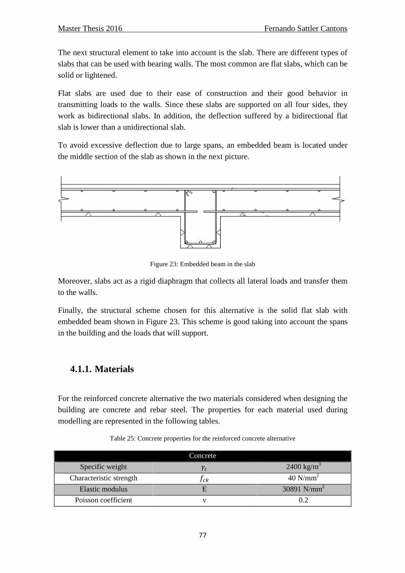
• Resistance
The structure should adequately withstand the loads for which it was designed; it can be obtained from a suitable structural analysis, whose accuracy is increasing due to advances in computational methods and probabilistic safety studies.
• Durability
The structure must remain in good strength conditions, functionality and appearance for the period of time for which it was designed, under the conditions of use and environmental exposure. To achieve this, the structure has to have a proper design, construction and maintenance.
• Stability
The structure must maintain the configuration that was originally conceived against external actions. This implies that there must be a balance of all the forces that are acting on it to satisfy the condition of total equilibrium.
• Behavior during service
During the life of the structure, it must submit acceptable service conditions. Among the main aspects to be considered at this point it has to be taken into account the following: horizontal and vertical deformation of structural elements, concrete cracking (the cracked surface of concrete creates a sense of insecurity on people), perception of movement within the building (vibration).
• Construction feasibility
The structure has to be constructible. To that end, the design has to be done according to the available materials and the building techniques that better adapts to our needs.
• Cost
The cost of a structure is very important when selecting an alternative, since this will depend on the viability of the project. The designer should try to reduce costs as much as possible but without reducing the strength of the structure. This will be achieved from an adequate analysis of alternatives and cost, by varying factors such as the type of material or structural system used.
Master Thesis 2016 Fernando Sattler Cantons
20
2.2. Materials
The materials are the key factor in the structural behavior. The choice of the right materials is vital to ensure the different aspects mentioned above.
Each material has different properties that make it interesting when designing a structure. The problem is that often a single material is not enough to meet all the resistant needs of the building. For this reason, today the majority of materials used in construction are composite materials. Thus a composite material that combines all the advantages of each material is achieved that way and allows a good structural behavior.
The most significant case of composite material is reinforced concrete. The concrete itself is already a composite material, which thanks to its different components achieves a high compressive strength and durability. The problem lies in its tensile strength, which is very low (about 10% of its compressive strength). On the other hand steel is a material with very good tensile strength, even with reduced sections, making it ideal for combining with the concrete material.
The three materials considered in this paper will be: reinforced concrete, structural steel and precast concrete.
2.2.1. Reinforced concrete
Concrete is an artificial material obtained from the mixture of determined quantities of cement, aggregates and water. Cement and water create a paste that surrounds the aggregates, constituting a heterogeneous material. Sometimes, substances called admixtures and additions are added to modify some properties of the concrete.
There are many types of concrete available, created by varying the proportions of the main ingredients. In this way or by substitution for the cementitious and aggregate phases, the finished product can be tailored to its application with varying strength, density, or chemical and thermal resistance properties.
Mass concrete (without reinforcement) has a good compressive strength but is weak against tensile strength. This fact can be considered as a limiting factor in some structural applications. To provide concrete with greater tensile strength steel rods are used as reinforcement. The steel reinforcement is responsible of handling tensile strengths, providing concrete better properties as structural material. Reinforcement is also used to increase compressive resistance, as to reduce the cracking in concrete and deflections and to achieve major ductility on concrete.
The combination of concrete and steel rods constitutes the reinforced concrete.
Master Thesis 2016 Fernando Sattler Cantons
21
The advantages of reinforced concrete are:
1. Reinforced concrete has a high compressive strength compared to other building materials.
2. Due to the provided reinforcement, reinforced concrete can also withstand a good amount tensile stress. In addition, the relation cost-resistance is higher than other materials.
3. Fire and weather resistance of reinforced concrete is fair. 4. The reinforced concrete building system is more durable than any other building
system. 5. Reinforced concrete, as a fluid material in the beginning, can be economically
molded into a nearly limitless range of shapes. 6. The maintenance cost of reinforced concrete is very low. 7. In structure like footings, dams, piers etc. reinforced concrete is the most
economical construction material. 8. It acts like a rigid member with minimum deflection. 9. Compared to the use of steel in structure, reinforced concrete requires less
skilled labor for the erection of structure.
On the other hand, the disadvantages of reinforced concrete are:
1. The tensile strength of reinforced concrete is about one-tenth of its compressive strength.
2. The main steps of using reinforced concrete are mixing, casting, and curing. All of this affects the final strength.
3. The cost of the forms used for casting reinforced concrete is relatively higher.
4. Shrinkage causes crack development and strength loss.
2.2.1.1. Cement
Portland cement is the most common type of cement in general usage. It is a basic ingredient of concrete, mortar and many plasters. It consists of a mixture of calcium silicates (alite, belite), aluminates and ferrites - compounds which combine calcium, silicon, aluminium and iron in forms which will react with water. Portland cement and similar materials are made by heating limestone (a source of calcium) with clay and/or shale (a source of silicon, aluminium and iron) and grinding this product (called clinker) with a source of sulfate.
There are various types of cement, which are specified in the Eurocode 2:
Master Thesis 2016 Fernando Sattler Cantons
22
Table 1: Admissible cement for concrete types (European committee for standardization - 2002a)
2.2.1.2. Water
Combining water with a cementitious material forms a cement paste by the process of hydration. The cement paste glues the aggregate together, fills voids within it, and makes it flow more freely.
A lower water-to-cement ratio yields a stronger, more durable concrete, whereas more water gives a freer-flowing concrete with a higher slump. Impure water used to make concrete can cause problems when setting or in causing premature failure of the structure.
Hydration involves many different reactions, often occurring at the same time. As the reactions proceed, the products of the cement hydration process gradually bond together the individual sand and gravel particles and other components of the concrete to form a solid mass.
2.2.1.3. Aggregates
Fine and coarse aggregates make up the bulk of a concrete mixture. Sand, natural gravel and crushed stone are used mainly for this purpose. Recycled aggregates (from construction, demolition, and excavation waste) are increasingly used as partial replacements for natural aggregates, while a number of manufactured aggregates, including air-cooled blast furnace slag and bottom ash are also permitted.
Master Thesis 2016 Fernando Sattler Cantons
23
The presence of aggregate greatly increases the durability of concrete above that of cement, which is a brittle material in its pure state, and also reduces cost and controls cracking caused by temperature changes. Thus concrete is a true composite material.
Redistribution of aggregates after compaction often creates inhomogeneity due to the influence of vibration. This can lead to strength gradients.
According to Eurocode 2, the general requirements for maximum D and minimum d sizes are:
Table 2: Maximum D and minimum d sizes (European committee for standardization - 2002a)
2.2.1.4. Admixtures
Admixtures shall be understood to mean those substances or products which, once incorporated into concrete prior to or during mixing or additional mixing in individual proportions not exceeding 5% of the weight of the cement, ensure the desired alteration, in the fresh or hardened state, in any of the concrete’s characteristics, usual properties or performance.
Five types of admixtures, as indicated on Eurocode 2, shall be considered:
Master Thesis 2016 Fernando Sattler Cantons
24
Table 3: Types of admixtures and functions (European committee for standardization - 2002a)
2.2.1.5. Additions
Additions are those inorganic or pozzolanic materials, or materials with latent hydraulicity, which, when finely divided can be added to concrete in order to improve one of its characteristics or to endow it with special properties.
Eurocode 2 only covers fly ash and silica fumes added to concrete at the time of casting.
Fly ash is the solid residue collected by electrostatic precipitation or mechanical trapping of the dust accompanying the combustion gases of pulverized coal-fed thermoelectric plant burners.
Silica fumes are a by-product obtained during the reduction of high-purity quartz, with carbon in electric arc furnaces for the production of silicon and ferrosilicon.
Additions may be used as concrete constituents provided that evidence can be provided of their suitability for use, and that the desired effect can be achieved without negatively impact on the concrete’s characteristics or posing a risk to the concrete’s durability or the corrosion-resistance of its reinforcements.
2.2.1.6. Steel
Master Thesis 2016 Fernando Sattler Cantons
25
As mentioned before, steel provides concrete with tensile strength. According to Eurocode 2, passive reinforcement is achieved by using, mainly, two types of bars: ribbed weldable steel bars and ribbed weldable steel supplied in coils.
The possible nominal diameters of ribbed bars shall be as defined in the following series:
6 - 8 - 10 - 12 - 14 - 16 - 20 - 25 - 32 and 40 mm.
Apart from in the case of electro-welded mesh fabrics or basic lattice reinforcements, diameters of less than 6 mm shall be avoided wherever any welding technique, either resistant or non-resistant, is used in the making or installation of passive reinforcements.
The types of ribbed steel are defined in the following table:
Table 4: Properties of the different types of steel (European committee for standardization - 2002a)
The most common ribbed steel used in reinforced concrete is B500S.
2.2.2. Structural steel
Structural steel is a category of steel used as a construction material for making structural steel shapes. A structural steel shape is a profile, formed with a specific cross section and following certain standards for chemical composition and mechanical
Master Thesis 2016 Fernando Sattler Cantons
26
properties. Structural steel shapes, sizes, composition, strengths, storage practices, etc., are regulated by standards.
Structural steel is an industrial production material which ensures that has adequate quality control. This material is characterized by high strength, rigidity and ductility, making it a material widely used for the projection of earthquake-resistant structures.
There are many types of structural steel depending on their yield strength or their welding capability under certain conditions. Eurocode 3 takes into account the following types:
Table 5: Types of structural steel (European committee for standardization - 2002a)
Table 6: Minimum yield strength and ultimate yield strength (N/mm2) (European committee for
standardization - 2002a)
Figure 1: Structural steel profiles
Master Thesis 2016 Fernando Sattler Cantons
27
The advantages of structural steel are:
1. high strength and stiffness per weight 2. Ease of fabrication and mass production 3. fast and easy erection and installation 4. Substantial elimination of delays due to weather 5. More accurate detailing 6. Non-shrinking and non-creeping at ambient temperature 7. formwork unneeded 8. Termite proof and rot proof 9. Uniform quality 10. Economy in transportation and handling
On the other hand, the disadvantages of structural steel are:
1. Susceptibility to corrosion 2. Low fire resistance 3. Buckling and high deformation due to small sizes of members
2.2.3. Precast concrete
Precast concrete is a construction product produced by casting concrete in a reusable mold or form which is then cured in a controlled environment, transported to the construction site and lifted into place. In contrast, standard concrete is poured into site-specific forms and cured on site.
By producing precast concrete in a controlled environment (typically referred to as a precast plant), the precast concrete is afforded the opportunity to properly cure and be closely monitored by plant employees. Utilizing a Precast Concrete system offers many potential advantages over site casting of concrete. The production process for Precast Concrete is performed on ground level, which helps with safety throughout a project. There is a greater control of the quality of materials and workmanship in a precast plant rather than on a construction site. Financially, the forms used in a precast plant may be reused hundreds to thousands of times before they have to be replaced, which allow cost of formwork per unit to be lower than for site-cast production.
Master Thesis 2016 Fernando Sattler Cantons
28
Figure 2: Prefabrication plant
Within precast concrete it can be find two types of concrete: prestressed concrete and post-tensioning concrete. The idea of prestressing is the same in both cases but the technique to apply stresses is different. The difference lies in that the prestressing cable is tensioned prior to hardening of the concrete and the post-stressing after the concretes hardening.
This technique is often employed in concrete beams, columns, spandrels, single and double tees, wall panels, segmental bridge units, bulb-tee girders, I-beam girders, and others. Prestressed elements are crack-free under working loads and, as a result, look better and more watertight, providing better corrosion protection for the steel.
The advantages of precast concrete are:
1. The concrete of superior quality is produced as it is possible to have better technical control on the production of concrete in factory.
2. It is not necessary to provide joints in the precast construction. 3. The labor required in the manufacturing process of the precast units can easily be
trained. 4. The molds employed for preparing the precast units are of steel with exact
dimension in all directions. These molds are more durable and they can be used several times.
5. The precast articles may be given the desired shape and finish with accuracy. 6. The precast structures can be dismantled, when required and they can then be
suitably used elsewhere. 7. The transport and storage of various components of concrete for cast in situ work
are eliminated when precast members are adopted. 8. The work can be completed in a short time, when precast units are adopted. 9. When precast structures are to be installed, it is evident that the amount of
scaffolding and formwork is considerably reduced.
Master Thesis 2016 Fernando Sattler Cantons
29
The disadvantages of precast concrete are:
1. If not properly handled, the precast units may be damaged during transport. 2. It becomes difficult to produce satisfactory connections between the precast
members. 3. It is necessary to arrange for special equipment for lifting and moving of the
precast units. 4. The economy achieved in precast construction is partially balanced by the amount
to be spent in transport and handling of precast members. It becomes therefore necessary to locate the precast factory at such a place that transport and handling charges are brought down to the minimum possible extent.
2.2.3.1. Concrete
The precast concrete and especially for prestressed generally has a higher strength than normal concrete used in reinforced concrete structures because the precast concrete provides greater compressive load thus achieving lower dimension of the elements and thus less dead load.
2.2.3.2. Active reinforcement steel
Active reinforcements refer to the configurations of high strength steel elements by means of which the structure is prestressed. These may comprise wires, bars or strands.
It must be taken into account that corrosion is a critical factor for prestressing steel, since the tensile strength is linked with the area and, if the area is reduced, resistance decreases and can produce a premature failure. In the prestressed concrete, corrosion protection is given by concrete but, in post-stressing concrete, the steel is not in contact with concrete, then corrosion can be avoided by injecting cement grout or grease into the sheath after the end of the post-tensioning process.
Master Thesis 2016 Fernando Sattler Cantons
30
Figure 3: Prestressing steel strands
Eurocode 2 takes into account the following active reinforcement elements:
- Wires:
Table 7: Types of prestressing wires (European committee for standardization - 2002a)
Master Thesis 2016 Fernando Sattler Cantons
31
- Strands:
Table 8: Strands of 2 or 3 wires (European committee for standardization - 2002a)
Table 9: Strands of 7 wires (European committee for standardization - 2002a)
- Bars:
The mechanical characteristics of prestressing bars, determined from the tensile test carried out in accordance with UNE-EN ISO 15630-3 shall satisfy the following requirements:
- Maximum unit load fmax shall not be less than 980 N/mm².
- The yield strength fy shall be between 75 and 90% of the maximum unit load fmax. This ratio shall be satisfied not only by the minimum guaranteed values but also by each of the bars tested.
- Elongation at maximum load measured on a longitudinal base of 200 mm or more shall not be less than 3.5%.
- Their modulus of elasticity shall be the value guaranteed by the manufacturer, with a ± 7% tolerance.
Bars shall withstand the bending test specified in UNE-EN ISO 15630-3, without breaking or cracking.
Relaxation at 1,000 hours at a temperature of 20 ± 1º C and for an initial tensile stress of 70% of the guaranteed maximum unit load shall not exceed 3%.
Master Thesis 2016 Fernando Sattler Cantons
32
3. Structural analysis
As discussed in the first chapter, design and structural analysis of two different buildings will be made. The two buildings are intended for different uses and therefore its structural design is also different. Both buildings are located in the city of Trondheim in Norway. It is for this reason that the design and analysis of the buildings will focus on the actions in that territory.
Normally the structural design of buildings is a result of certain initial and/or boundary conditions, such as the location of the building, the climate it will be subjected and must withstand loads. After the assessment of all those conditions and the combination of these, the designer must make an appropriate design of the various structural elements of the building. The same applies to the geometry of the building. In addition, it’s necessary to choose the suitable materials to withstand such loads.
Before starting the design of the structure and their elements it’s necessary to carry out a structural analysis. This analysis will determine actions acting on the structure and the effect they cause on it. Thus, structural analysis can be considered a cause-effect analysis.
Once these effects have been obtained (moments, shear forces, stresses, strains, etc.), one may proceed to design the right elements to address the actions considered.
3.1. Hypothesis
For structural evaluation some assumptions have been made in order to simplify the design phase and cost analysis.
First of all, foundations will not be taken into account in this analysis. It is considered that the foundations are sufficient for all structural typologies and independent of the material used. This measure makes the cost analysis does not depend on the foundation elements, although in reality it does.
On the other hand, since the exact location of the buildings is not defined, the characteristics of the dominant ground type in the city of Trondheim will be taken into account. Therefore, it was considered that the type of ground found more frequency in the city is rock, with possible thin layers of other materials on this.
Master Thesis 2016 Fernando Sattler Cantons
33
3.2. Description of the buildings
3.2.1. Building 1: Residential building
The first building is intended for residential use and has five habitable floors. On each floor there are four apartments with identical dimensions (42 m2 of living area). The height of each floor is 2.6 meters, except the first floor in which the height is 4.55 meters due to the existence of a loft space. The plan dimensions of the building are a 26x7.16 meter which means a floor area of 186.16 m2 per story.
Regarding the structural configuration, the resistant scheme of the building is based on bearing walls. On one hand there’s a perimeter bearing wall, which has the greatest thickness (0.25 m). The frontal bearing wall is 0.15 m thick. On the other hand there’re partition bearing walls (0.20 m) that separates and limit the surface for each apartment. The interior partitions of each apartment are non-structural.
This configuration creates spans of 6.50 m in X-direction and 7.16 m in Y-direction which have to be saved using an adequate floor configuration with enough stiffness to guarantee stability and serviceability comfort.
The following structural diagrams represent the configuration adopted. View presented both in elevation and plan.
Figure 4: Residential building front view
Master Thesis 2016 Fernando Sattler Cantons
34
Figure 5: Residential building plan view
3.2.2. Building 2: Office building
The second building is intended for office use and has also five usable floors. Since the use for which the building is designed requires the greatest possible open space, no internal separations (structural) on different floors have been considered. Internal partitions are out of the scope of this thesis due to the fact that they can be built using non-structural partitions.
The height of each floor is 3 meters which allows space enough to host the different installations and systems. The plan dimensions of the building are 30x20 meters, which supposes a useful area of 600 m2 per story.
The resistant structural scheme is based on stiff frames formed by beams and columns in both directions. This bidirectional configuration creates spans of 6 meters in X-direction and 5 meters in Y-direction. That means that there are five frames (porticos) in X-direction and four frames (porticos) in Y-direction.
Once again, the floor and deck system will be designed in order to be stiff enough to fulfill with the standards (Eurocodes).
The following structural diagrams represent the configuration adopted. View presented both in elevation and plan.
Master Thesis 2016 Fernando Sattler Cantons
35
Figure 6: Office building front view
Figure 7: Office building plan view
Master Thesis 2016 Fernando Sattler Cantons
36
3.3. Actions
In order to make an adequate structural design or analysis, it is necessary to know all the loads acting on the structure and their value. The value of the actions may be known or unknown. In the latter case we must appeal to the rules for estimating the value of such actions and to carry out structural analysis.
A building or generally a structure has to be designed considering two types of loads: vertical or gravitational loads and lateral loads. Gravitational loads correspond to the structure self-weight and the summation of all the loads contained in the building shape. On the other hand, lateral loads correspond to wind action and seismic effects.
Actions can appear for different reasons and may have different origins, but consider it is always necessary to define the problem.
Actions may be classified according to variation over time in the following groups:
- Permanent action (G): actions that take place at all times and have a constant magnitude and position. This group includes the dead weight of the structure, flooring and pavements, auxiliary elements, fixed installations, etc.;
- permanent actions of inconstant value (G* ): actions that take place at all times but whose magnitude is not constant and varies monotonously, such as differed movements in foundations;
- Variable actions (Q): actions whose value frequently varies over time and in a non-monotonous way. This group includes service overloads, environment actions, actions due to construction processes, etc.;
- Accidental actions (A): actions with a low probability of incidence throughout the design working life of the structure but which are of significant magnitude. This group includes actions due to impact, explosions, etc. Earthquakes may be considered to be of this type.
3.3.1. Self-weight load
This load corresponds to the weight of the structural element itself and may vary depending on the material, shape and volume. In this thesis, the main materials considered are concrete and steel, which satisfies the three structural patterns considered (reinforced concrete, structural steel and precast concrete).
Master Thesis 2016 Fernando Sattler Cantons
37
The self-weight of the elements has been computed according to the following values:
Plain concrete: 2300 �� ��⁄ ��� ≤ 50�/���
2400 �� ��⁄ ��� > 50�/���
Reinforced or prestressed concrete: 2500 �� ��⁄
Structural and reinforcement steel: 7850 �� ��⁄
3.3.2. Dead loads
These loads are considered as permanent loads. Their magnitude can be constant along time or can vary at one point. In this analysis, only constant value dead loads had been considered. In this way, the elements considered as dead loads are non-structural walls and partitions, impervious isolation layers in floors, tilling elements and its corresponding mortar layer and all the equipment needed to satisfy the function of the building (Heating and cooling systems, electric equipment, pipes and ducts, etc.).
The value of these actions has been taken from the Eurocode 1 part 1-1, and is represented on the following tables.
Dead loads considered in floors:
Table 10: Considered dead loads
Element Load Units
Separation walls (<0.25 m) 1.4 kN/m2
Hydraulic tile and mortar layer
1.0 kN/m2
Heating, cooling and electric installation
0.5 kN/m2
Total 2.90 kN/m2
The resultant load to consider in calculations is 2.90 kN/m2 but to simplify the input data on calculations the load will be considered 3 kN/m2.
Dead load considered on the roof:
In this particular case, the standards considerer that the dead load on the roof of the building is lower than in the lower floors so it assign a fix value of 1.50 kN/m2.
Master Thesis 2016 Fernando Sattler Cantons
38
3.3.3. Live loads
Live loads are the consequence of the usage of the building and their origin may be very different. The values of these loads are tabulated and specified in all design and construction standards.
Once more, the values of the live loads taken into account were extracted from the Eurocode 1 part 1-1.
Table 11: Considered live loads
Definition Load Units
Residential buildings 2.0 kN/m2
Office buildings 2.0 kN/m2
Roof live load 1.0 kN/m2
3.3.4. Snow loads
These loads are highly dependent on the geography and the height of the building location. Snow loads can be considered as live loads due to its temporary nature. Snow will only be considered on roof elements in the building, and in all the places that could gather snow.
Moreover, the load depends of the roof shape. The load is not the same in a flat roof and in an inclined one. For the cases of study the roof is considered flat in both cases.
The loads are specified in Eurocode 1 part 1-3 and can be determined using the following expression:
� = � · �� · �� · �
Where,
� is the snow load shape coefficient
�� is the exposure coefficient
�� is the thermal coefficient
� is the characteristic value of snow load on the ground
Master Thesis 2016 Fernando Sattler Cantons
39
The value of � depends on the roof configuration. The value can be found using the following graph (Figure 5.1 in Eurocode 1 part 1-3), where α is the roof angle with respect to the horizontal plane.
It can be seen that for a flat roof the value is 0.8.
In the other hand, the exposure coefficient can be found in the table 5.1 of EC1 part 1-3.
For normal conditions �� = 1.
Table 12: Types of topography and associated exposure coefficient (European committee for
standardization - 2002a)
According to Eurocode 1, the thermal coefficient �� should be used to account for the reduction of snow loads on roofs with high thermal transmittance (> 1 W/m2 K), in particular for some glass covered roofs, because of melting caused by heat loss.
Master Thesis 2016 Fernando Sattler Cantons
40
For all other cases:
�� = 1
Finally, the value of the snow load on the ground (� ) can be obtained according to the following map.
Figure 9: Snow loads on the ground for Norway (European committee for standardization - 2002a)
Then, the load considered in calculation according to the location of the city of Trondheim will be 4.75 kN/m2.
As a result, the snow load considered in the calculations will be:
The loads generated by the wind are dependent of multiple factors such as building height, building plan shape, orientation, geographic area, terrain characteristics and so on.
The definition of the snow load is made by applying the graphs and tables in Eurocode 1 part 1-4, that allows us to obtain the pressure coefficient to take into account.
Master Thesis 2016 Fernando Sattler Cantons
41
The pressure coefficient can be obtained from the table 7.1 of the standard (Eurocode 1 part 1-4): Recommended values of external pressure coefficients for vertical walls on rectangular shape buildings.
The relationship between the height and plan dimensions of the building and the profile of velocity pressure is the following:
Figure 10: Relationship between height and plan dimensions for wind pressure coefficient
Master Thesis 2016 Fernando Sattler Cantons
42
The expression to compute the wind pressure over a vertical wall is:
!� = "#�$ · ��%&�' · �(�
For Norway the product of "#�$ · ��%&�' can be taken directly from a table. This value
depends on the geographic area and the altitude taken into account.
Table 14: Wind speed for the different geographic areas (European committee for standardization -
2002a)
Curve Wind speed (m/s)
A ) = 11.7%*+�,-. + 2'with Z ≥ 6 m, corresponding to v = 35 m/s and Z = 10 m. Applicable in regions with moderate wind, lower lands of the interior zones for instance.
B ) = 13.3%*+�,-. + 2'with Z ≥ 6 m, corresponding to v = 40 m/s and Z = 10 m. Applicable in regions with strong wind.
C ) = 80% of curve A with Z ≥ 6 m, corresponding to v = 28 m/s and Z = 10 m. Applicable to structures located in densely built zones. Not applicable in zones with severe climate.
D ) = 80% of curve B with Z ≥ 6 m, corresponding to v = 32 m/s and Z = 10 m. Applicable to structures located in densely built zones and zones with severe climate. Not applicable in zones where curves E or F are used.
E ) = 15%*+�,-. + 2'with Z ≥ 6 m, corresponding to v = 45 m/s and Z = 10 m. Applicable in regions with strong wind.
F ) = 16.7%*+�,-. + 2'with Z ≥ 6 m, corresponding to v = 50 m/s and Z = 10 m. Applicable in regions with very strong wind.
Then, the final expression to determine the wind pressure load will be:
!� = 22 · )� · �(�
With ρ = 1.25 kg/m3 being the density of the air.
3.3.6. Seismic loads
Put into a global scale, Norway can be seen as a low to intermediate seismicity area. An analysis of historical data can indicate that earthquakes with a magnitude of 5 or larger on the Richter scale be expected to have a return period of 10 years according to NORSAR. Earthquakes with a magnitude of 6 or larger will have a return period of 100 years.
Strong ground motion in the vicinity of an earthquake source is characterized by strong velocity pulses with high energy concentration. The velocity pulses are more prominent in the forward direction, i.e., at stations towards which the fault rupture propagates. The
Master Thesis 2016 Fernando Sattler Cantons
43
concentration of seismic energy in one or a few cycles of strong pulses causes severe lateral displacement demands on engineering structures. On the other hand, the high frequency energy is relatively lower.
Figure 11: Norwegian Seismic zoning maps, contour lines for annual probability of 2.1⋅10-3 (NORSAR)
From the previous figure, it can be determined that the ground acceleration (ag/g) for Trondheim is 0.4.
To define the design earthquake is necessary to know the elastic response spectrum. This elastic response spectrum depends on the type of ground in which the structure will be located.
The standard that regulates the seismic behavior of structures and its calculation is Eurocode 8. Then, the elastic response spectrum will be determined according to Eurocode 8.
As stated in previous chapters, to model and compute the structural response of the buildings, the software ETABS 2015 will be used. This software includes the elastic response spectra in the database, so it is not necessary to predefine or model it. Then, only the type of land on which the structure is built will be needed.
According to Eurocode 8 there are five typical ground types (A, B, C, D, E) and 2 special ground types (S1, S2) that may be used to account for the influence of local ground conditions on the seismic action. The average shear wave velocity in the top 30 m from the surface is computed according to the following equation:
Master Thesis 2016 Fernando Sattler Cantons
44
Where,
hi and vi denote the thickness (in meters) and the shear wave velocity (at a shear strain level of 10-5 or less) for the i-th formation or layer, in a total of N.
If the value of vs,30 is not available, the number of block outs per 0.3 m in ΝSPT test can be used. If this number is not available either, the undrained cohesion “Cu” can be used.
The following table presents the description of each ground type, and the definition parameters.
Table 15: Seismic parameters for the different ground types (European committee for standardization. (2004c) Table 3.1)
Ground type that best suited to the geology of Trondheim is soil A; so it is this type of ground which will be taken into account when modeling the structures.
Master Thesis 2016 Fernando Sattler Cantons
45
The elastic response spectrum shape is defined in the following figure:
TB is the lower limit of the period of the constant spectral acceleration branch
TC is the upper limit of the period of the constant spectral acceleration branch
TD is the value defining the beginning of the constant displacement response range of the spectrum
S is the soil factor
The parameters that define the shape of the spectrum depend on the ground type and can be obtained from the tables on Eurocode 8.
Eurocode 8 defines 2 spectrum types: Type 1 for regions with high seismic activity (defined as Μ > 5,5), and Type 2 for regions with average seismic activity (Μ < 5,5). Spectrums for each ground type are presented that include ground types: Α - rock , Β – very dense sand, gravel or very stiff clay, C – dense or medium dense sand, gravel or stiff clay, D – loose-to-medium cohesionless soil (with or without some soft cohesive layers), or of predominantly soft-to-firm cohesive soil, Ε – soil profiles consisting of a
Master Thesis 2016 Fernando Sattler Cantons
46
surface alluvium layer with vs values of type C or D and thickness varying between about 5 m and 20 m, underlain by stiffer material. The vertical axis is the spectral acceleration of an elastic structure normalized to the ag.
Table 16: Values for the elastic response spectrum Type 1
(European committee for standardization. (2004c) Table 3.2)
Table 17: Values for the elastic response spectrum Type 2
(European committee for standardization. (2004c) Table 3.3)
Master Thesis 2016 Fernando Sattler Cantons
47
According to the parameters stated above, the following figures present the elastic response spectrums defined by Eurocode 8 for each ground type.
Figure 13: Elastic response spectrum Type 1 for damping 5%
(European committee for standardization. (2004c) Figure 3.2)
Figure 14: Elastic response spectrum Type 2 for damping 5%
(European committee for standardization. (2004c) Figure 3.3)
Master Thesis 2016 Fernando Sattler Cantons
48
In the calculations, only the horizontal displacement due to earthquake will be taken into account. Seismic actions will be considered acting on the two planes of the building plan, with its assigned values specified in Eurocode 8.
3.3.7. Combination of actions
The possible combinations of actions shall be established for each of the situations studied. A combination of actions shall consist of a set of compatible actions which shall be considered as acting simultaneously for a specific check.
Each combination will usually comprise permanent actions, one determinant variable action and one or more concomitant variable actions. Any of the variable actions may be the determinant action.
The combinations will depend on the limit states. For Ultimate limit states (ULS) and serviceability limit states (SLS) the combinations may vary by introducing different coefficients.
The representative value of an action is the value used to check its limit states.
One action may have one or more representative values, depending on its type.
The representative value of an action is its characteristic value Fk or this as affected by a simultaneity factor Ψi:
Ψi·Fk
The characteristic values of actions shall be those given in the regulations on actions in force.
Table 18: Simultaneity factors for service overloads in buildings (European committee for standardization
- 2002a)
Master Thesis 2016 Fernando Sattler Cantons
49
Table 19: Simultaneity factors for snow action (European committee for standardization - 2002a)
Table 20: Simultaneity factors for wind action (European committee for standardization - 2002a)
3.3.7.1. Ultimate limit states
The combinations of actions for the different design situations shall be defined according to the following expressions:
In persistent or temporary situations:
In accidental situations:
In earthquake situations:
Where,
Gk,j characteristic value of permanent actions;
G*k,j characteristic value of permanent actions with a non-constant value;
Master Thesis 2016 Fernando Sattler Cantons
50
Qk,1 characteristic value of the determinant variable action;
ψo,i Qk,i representative value of a combination of variable actions acting at the same time as the determinant variable action;
ψ1,1 Qk,1 frequent representative value of the determinant variable action;
ψ2,i Qk,I quasi-permanent representative value of variable actions acting at the same time as the determinant variable action and the accidental action, or with an earthquake;
Ak characteristic value of the accidental action;
AE,k characteristic value of earthquake action.
In persistent or temporary situations where there is no obvious determinant action Qk,1, different possibilities will be assessed, considering different variable actions as the determinant action.
Partial factors for actions, for assessing ultimate limit states:
Table 21: Partial factors for actions (Ultimate limit states) (European committee for standardization -
2002a)
3.3.7.2. Serviceability limit states
Only persistent and temporary design situations are considered for these limit states. In these cases, combinations of actions shall be defined according to the following expressions:
Master Thesis 2016 Fernando Sattler Cantons
51
Unlikely combination:
Frequent combination:
Quasi-permanent combination:
Partial factors for actions, for assessing serviceability limit states:
Table 22: Partial factors for actions (Serviceability limit states) (European committee for standardization -
2002a)
3.4. Design formulation
The aim of this section is to present the considerations and the methodology used for the design of the different structural elements considered. It is not intended to reproduce verbatim the regulations or standards in question, so in each case appropriate references to the standards and formulation will be made.
It must be remembered that Eurocodes have been the reference standards in all cases.
Master Thesis 2016 Fernando Sattler Cantons
52
3.4.1. Reinforced concrete alternative
3.4.1.1. Concrete cover and spacing of bars
Concrete cover
The concrete cover over the reinforcement bars will be held according with the statements done in EC2 4.4.1 taking into consideration the durability of the elements. To properly design the correct cover it will be necessary to identify the environmental conditions for each case and the corresponding exposure class appealing to EC2 Table 4.1.
Spacing of bars
“The spacing of bars shall be such that the concrete can be placed and compacted satisfactorily for the development of adequate bond.” The recommendations for bars spacing and distribution are extracted from EC2 8.2.
3.4.1.2. Column design
Columns will be subjected to biaxial bending moments and axial load. Then, a proper design has to be done to withstand those loads. Moreover, shear forces will be present due to the interaction of the different elements (beams and columns) and that has to be taken into account as well.
Bending
Bending will be considered taking into consideration the recommendations proposed in EC2 6.1. One of the most important considerations is the following:
“For cross-sections loaded by the compression force it is necessary to assume the minimum eccentricity, eo = h/30 but not less than 20 mm where h is the depth of the section” (EC2 6.1 - 4). Since biaxial moment is acting in the vertical element the previous consideration has to be extended to both axes. Then, EC2 5.8.9 takes into account that behavior defining the eccentricities from where the design will be carried.
Master Thesis 2016 Fernando Sattler Cantons
53
Figure 15: Definition of eccentricities ey and ez (European
committee for standardization – 2004a) Figure 5.8)
The design reinforcement to cope bending moments is design according to the recommendations in EC2 9.5.2 and are as follows: “The total amount of longitudinal reinforcement should not be less than As,min.”
34,678 = max <0.10��=�>= ; 0.0023�@
“The area of longitudinal reinforcement should not exceed As,max.” “The recommended value is 0.04·Ac outside lap locations unless it can be shown that the integrity of concrete is not affected and that the full strength is achieved at ULS. This limit should be increased to 0.08·Ac at laps.”
Shear The shear reinforcement will be available using fences and stirrups so as to cope traversal actions, following the recommendations of bent and disposition set out in sections 8.3 and 8.7 respectively on Eurocode 2. The general design and verification for the shear forces are done according to EC2 6.2.1, where the shear resistance of the element is defined as follows: AB= = AB=,4 + A��= + A�=
Where,
Master Thesis 2016 Fernando Sattler Cantons
54
VRd,c is the design shear resistance of the member without shear reinforcement. VRd,s is the design value of the shear force which can be sustained by the yielding
shear reinforcement. VRd,max is the design value of the maximum shear force which can be sustained by the
member, limited by crushing of the compression struts. Vccd is the design value of the shear component of the force in the compression area,
in the case of an inclined compression chord. Vtd is the design value of the shear component of the force in the tensile
reinforcement, in the case of an inclined tensile chord. For structural elements not requiring design shear reinforcement, verifications have to be done following the rules stated in EC2 6.2.2. In addition, minimum shear reinforcement must be placed according to formulation collected in EC2 9.2.2. For structural elements requiring design shear reinforcement, verifications and design have to be done following the rules stated in EC2 6.2.3 to obtain the necessary transversal reinforcement. Since the specific elements in this particular case are columns, some rules have to be fulfilled for this kind of elements such as minimum bar diameter or bar spacing. These rules can be found on EC2 9.5.3 and are the following: (1) The diameter of the transverse reinforcement (links, loops or helical spiral reinforcement) should not be less than 6 mm or one quarter of the maximum diameter of the longitudinal bars, whichever is the greater. The diameter of the wires of welded mesh fabric for transverse reinforcement should not be less than 5 mm. (2) The transverse reinforcement should be anchored adequately. (3) The spacing of the transverse reinforcement along the column should not exceed Scl,tmax which can be determined as the least of:
- 20 times the longitudinal reinforcement diameter
- The lesser dimension of the column
- 400 mm (4) The maximum spacing required in (3) should be reduced by a factor 0.6:
(i) in sections within a distance equal to the larger dimension of the column cross-section above or below a beam or slab;
(ii) near lapped joints, if the maximum diameter of the longitudinal bars is greater than 14 mm. A minimum of 3 bars evenly placed in the lap length is required.
Master Thesis 2016 Fernando Sattler Cantons
55
(5) Where the direction of the longitudinal bars changes, (e.g. at changes in column size), the spacing of transverse reinforcement should be calculated, taking account of the lateral forces involved. These effects may be ignored if the change of direction is less than or equal to 1 in 12. (6) Every longitudinal bar or bundle of bars placed in a corner should be held by transverse reinforcement. No bar within a compression zone should be further than 150 mm from a restrained bar.
3.4.1.3. Beam design
Beams will be subjected to bending moments and shear forces due to the structural configuration of the building.
As done for the column case, the design criteria follows the recommendations stablished in Eurocode 2.
Bending
Bending will be considered taking into consideration the recommendations proposed in EC2 6.1 to determine the ultimate bending resistance of the element. To do it, some assumptions will be made:
- Plane sections remain plane.
- The strain in bonded reinforcement or bonded prestressing tendons, whether in tension or in compression, is the same as that in the surrounding concrete.
- The tensile strength of the concrete is ignored.
- The stresses in the concrete in compression are derived from the design stress/strain relationship (EC2 3.1.7.)
- The stresses in the reinforcing or prestressing steel are derived from the design curves in EC2 3.2 and 3.3.
- The initial strain in prestressing tendons is taken into account when assessing the stresses in the tendons.
The design is done according to the ultimate limit states (ULS) configuration.
Master Thesis 2016 Fernando Sattler Cantons
56
The determination of the maximum and minimum longitudinal reinforcement is done following the specifications in EC2 9.2.1.1:
“The area of longitudinal tension reinforcement should not be taken as less than As,min.”
34,678 = 0.26 $CDE$FG H�I but not less than 0.0013H�I
“Sections containing less reinforcement than As,min should be considered as unreinforced”
“The cross-sectional area of tension or compression reinforcement should not exceed As,max outside lap locations. The recommended value is 0,04Ac.”
Shear In this case, the same general approach adopted for columns can be applied for beams since stirrups are also used to collect shear stresses. The general design approach is collected in EC2 6.2. For structural elements not requiring design shear reinforcement, verifications have to be done following the rules stated in EC2 6.2.2. In addition, minimum shear reinforcement must be placed according to formulation collected in EC2 9.2.2. The minimum reinforcement per unit of length Asw can be computed by imposing the minimum value of the shear reinforcement ratio, using the following expressions:
2J = 34J� · HJ · �KL
2J,678 = 0.08 · M�� �>
Where, 2J is the shear reinforcement ratio (2J should not be less than 2J,678) 34J is the area of shear reinforcement within length s s is the spacing of the shear reinforcement measured along the longitudinal axis of
the member HJ is the breadth of the web of the member L is the angle between shear reinforcement and the longitudinal axis
Master Thesis 2016 Fernando Sattler Cantons
57
For structural elements requiring design shear reinforcement, verifications and design have to be done following the rules stated in EC2 6.2.3 to obtain the necessary transversal reinforcement.
Finally, as seen in EC2 9.2.2, the maximum separation between shear assemblies should not exceed Sl,max.
�N,6OP = 0.75I%1 + cot L'
3.4.1.4. Wall design
Walls are compression based elements where bending and shear can occur. To fully design the walls it is necessary to define their reinforcement, longitudinal (vertical and horizontal) and transversal.
The wall design is done according to EC2 9.6, where the following specification is made:
“This clause refers to reinforced concrete walls with a length to thickness ratio of 4 or more and in which the reinforcement is taken into account in the strength analysis. The amount and proper detailing of reinforcement may be derived from a strut-and-tie model. For walls subjected predominantly to out-of-plane bending the rules for slabs apply.” Since the designed walls fulfil the previous requirements, this clause can be applied. The vertical reinforcement design is done following the recommendations in EC2 9.6.2: (1) The area of the vertical reinforcement should lie between As,vmin and As,vmax. The recommended values for both parameters are: 34,T678 = 0.002 · 3�
34,T6OP = 0.04 · 3�
The previous As,vmax value is applicable outside lap locations unless it can be shown that the concrete integrity is not affected and that the full strength is achieved at ULS. This limit may be doubled at laps. (2) Where the minimum area of reinforcement, As,vmin, controls in design, half of this area should be located at each face.
Master Thesis 2016 Fernando Sattler Cantons
58
(3) The distance between two adjacent vertical bars shall not exceed 3 times the wall thickness or 400 mm whichever is the lesser.
The horizontal reinforcement design is done following the recommendations in EC2 9.6.3:
(1) Horizontal reinforcement running parallel to the faces of the wall (and to the free edges) should be provided at each surface. It should not be less than As,hmin. The recommended value is either 25% of the vertical reinforcement or 0,001·Ac, whichever is greater. (2) The spacing between two adjacent horizontal bars should not be greater than 400 mm. Finally, the transverse reinforcement is design based on the following rules (EC2 9.6.4): (1) In any part of a wall where the total area of the vertical reinforcement in the two faces exceeds 0.02·Ac, transverse reinforcement in the form of links should be provided in accordance with the requirements for columns (EC2 9.5.3). The large dimension referred to in EC2 9.5.3-(4)-(i) need not be taken greater than 4 x thickness of wall. (2) Where the main reinforcement is placed nearest to the wall faces, transverse reinforcement should also be provided in the form of links with at least of 4 per m2 of wall area.
3.4.1.5. Solid Slab design
Slabs have to withstand bending moments and shear forces provoked by the other structural elements. EC2 9.3 describes the design rules for solid slabs.
That section applies to one-way and two-way solid slabs for which b and leff are not less than 5h.
Flexure The recommendations are collected in EC2 9.3.1 and give the following statements:
Master Thesis 2016 Fernando Sattler Cantons
59
(1) For the minimum and the maximum steel percentages in the main direction 9.2.1.1 (1) and (3) apply.
Those steel percentages statements can be found on the beam part, in section 3.4.1.3 of this paper. (2) Secondary transverse reinforcement of not less than 20% of the principal reinforcement should be provided in one-way slabs. In areas near supports transverse reinforcement to principal top bars is not necessary where there is no transverse bending moment. (3) The spacing of bars should not exceed Smax,slabs. �6OP,4NOU4 = 3ℎ ≤ 400��
Where h is the total depth of the slab. (4) The rules given in EC2 9.2.1.3 (1) to (3), EC2 9.2.1.4 (1) to (3) and EC2 9.2.1.5 (1)
to (2) also apply but with WX = I.
Shear Shear reinforcement design is done according to EC2 9.3.2. The most important factor to take into account in this case is the depth if the slab. As stated in that section: “A slab in which shear reinforcement is provided should have a depth of at least 200 mm”. “In detailing the shear reinforcement, the minimum value and definition of reinforcement ratio in EC2 9.2.2 apply, unless modified by the following:”
In slabs, if |A�=| ≤ 1 3Z AB=,6OP (EC2 6.2), the shear reinforcement may consist entirely
of bent-up bars or of shear reinforcement assemblies.
3.4.1.6. Ribbed slab design
The design of this kind of slabs is done using the beam theory and, therefore, the same design formulation and considerations. The design considerations can be recovered from section 3.4.1.3 of this paper.
Master Thesis 2016 Fernando Sattler Cantons
60
Ribbed slabs can be considered as a union of T beams. As a result of their shape, additional considerations have to be done to define the overall shear resistance. This is the shear between web and flanges.
The design and verification process can be found in EC2 6.2.4 and takes into account the following recommendations:
(1) The shear strength of the flange may be calculated by considering the flange as a system of compressive struts combined with ties in the form of tensile reinforcement. (2) A minimum amount of longitudinal reinforcement should be provided, as specified in EC2 9.3.1.
(3) The longitudinal shear stress, VEd, at the junction between one side of a flange and the web is determined by the change of the normal (longitudinal) force in the part of the flange considered, according to:
A�= = ∆\=ℎ$ · ∆]
Where, h_ is the thickness of flange at the junctions ∆x is the length under consideration. ∆Fa is the change of the normal force in the flange over the length ∆x. (4) The transverse reinforcement per unit length Ast/Sf may be determined as follows: 34� · �>=�$ ≥ A�= · ℎ$cot c$
Master Thesis 2016 Fernando Sattler Cantons
61
Figure 16: Notations for the connections between flange and web (European
committee for standardization – 2004a) Figure 6.7)
To prevent crushing of the compression struts in the flange, the following condition should be satisfied: A�= ≤ ) · ��= · �Kc$ · d+�c$
3.4.2. Structural steel alternative
3.4.2.1. Column design
Composite concrete-steel columns are used in the structural design of the buildings and the applicable standard in that case is Eurocode 4.
Composite column members have to have a determinate maximum and minimum amount of steel contribution to be considered as composite. If not, the column can be considered as a concrete column or as a steel column. This range is defined in EC4 6.7.1.
0.2 ≤ e ≤ 0.9
e = 3O�>=�(N,B=
On the other side, there are some geometrical limitations on the design of these structural members, stated in EC4 table 6.3:
Master Thesis 2016 Fernando Sattler Cantons
62
Table 23: Maximum values (d/t), (h/t) and (b/tf) with fy in N/mm2 (European committee for
standardization. (2004b))
There are two design methods according EC4:
- A general method in EC4 6.7.2 whose scope includes members with non-symmetrical or non-uniform cross-sections over the column length and
- A simplified method in EC4 6.7.3 for members of doubly symmetrical and uniform cross section over the member length.
In this particular case, the simplified method is applicable and will be followed to design the columns. The resistance of the cross section of the columns should be evaluated according the criteria stated in EC4 6.7.3.2 and taking into consideration the M-N interaction diagram.
Master Thesis 2016 Fernando Sattler Cantons
63
Figure 17: Simplified interaction curve and corresponding stress distributions (European committee for
standardization. (2004b) Figure 6.19)
Bending Columns are subjected to compression and biaxial bending due to the frame system configuration. The considerations for the design and verification of these actions are taken into account in section 6.7.3.7 of the Eurocode 4 and are as follows: (1) For composite columns and compression members with biaxial bending the values �=> and �=g in EC4 Figure 6.20 may be calculated according to EC4 6.7.3.6 separately
for each axis. Imperfections should be considered only in the plane in which failure is expected to occur. If it is not evident which plane is the more critical, checks should be made for both planes.
(2) For combined compression and biaxial bending the following conditions should be satisfied for the stability check within the column length and for the check at the end: h>,i=�=>h(N,>,B= ≤ Lj,> hg,i=�=gh(N,g,B= ≤ Lj,g h>,i=�=>h(N,>,B= + hg,i=�=gh(N,g,B= ≤ 1,0 Where,
Master Thesis 2016 Fernando Sattler Cantons
64
h(N,>,B= and h(N,g,B= are the plastic bending resistances of the relevant plane of
bending; h>,i= and hg,i= are the design bending moments including second-order effects
and imperfections according to 6.7.3.4; �=> and �=g are defined in EC4 6.7.3.6;
Lj,> = Lj and Lj,g = Lj are given in EC4 6.7.3.6(1).
Shear Shear in composite columns is taken into account in EC4 6.7.4 and then the most important considerations for the design are shown: “For composite columns and compression members no shear connection need be provided for load introduction by endplates if the full interface between the concrete section and endplate is permanently in compression, taking account of creep and shrinkage. Otherwise the load introduction should be verified according to (5). For concrete filled tubes of circular cross-section the effect caused by the confinement may be taken into account if the conditions given in EC4 6.7.3.2(6) are satisfied using the values ηa and ηc for λ equal to zero.” “If the concrete in a filled circular hollow section or a square hollow section is only partially loaded, for example by gusset plates through the profile or by stiffeners as shown in Figure 6.22, the local design strength of concrete, σc,Rd under the gusset plate or stiffener resulting from the sectional forces of the concrete section should be determined by:
where: t is the wall thickness of the steel tube; a is the diameter of the tube or the width of the square section; Ac is the cross sectional area of the concrete section of the column; A1 is the loaded area under the gusset plate, see EC4 Figure 6.22; ηcL = 4,9 for circular steel tubes and 3,5 for square sections.
Master Thesis 2016 Fernando Sattler Cantons
65
To consider longitudinal shear and the interaction between concrete and steel on the interface, recommendations given in EC4 6.7.4.3 should be followed:
(1) Outside the area of load introduction, longitudinal shear at the interface between concrete and steel should be verified where it is caused by transverse loads and /or end moments. Shear connectors should be provided based on the distribution of the design value of longitudinal shear, where this exceeds the design shear strength τRd. (2) In absence of a more accurate method, elastic analysis, considering long term effects and cracking of concrete, may be used to determine the longitudinal shear at the interface. (3) Provided that the surface of the steel section in contact with the concrete is unpainted and free from oil, grease and loose scale or rust, the values given in EC4 Table 6.6 may be assumed for τRd.
(4) The value of τRd given in Table 6.6 for completely concrete encased steel sections applies to sections with a minimum concrete cover of 40mm and transverse and longitudinal reinforcement in accordance with 6.7.5.2. For greater concrete cover and adequate reinforcement, higher values of τRd may be used. Unless verified by tests, for completely encased sections the increased value βcτRd may be used, with βc given by:
p� = 1 + 0.02dg q1 − dg,678dg s ≤ 2.5
Where: cz is the nominal value of concrete cover in mm, see Figure 6.17a;
Master Thesis 2016 Fernando Sattler Cantons
66
cz,min = 40 mm is the minimum concrete cover.
(5) Unless otherwise verified, for partially encased I-sections with transverse shear due to bending about the weak axis due to lateral loading or end moments, shear connectors should always be provided. If the resistance to transverse shear is not be taken as only the resistance of the structural steel, then the required transverse reinforcement for the shear force Vc,Ed according to EC4 6.7.3.2(4) should be welded to the web of the steel section or should pass through the web of the steel section.
3.4.2.2. Beam design
Beams will be subjected to bending moments and shear forces due to the structural configuration of the building.
The design criteria follows the recommendations stablished in Eurocode 3.
Bending
The design to make front the different bending actions is done following the rules collected in EC3 6.2.5.
The most important rules are the following:
“The design value of the bending moment h�= at each cross-section shall satisfy:”
h�=h�,B= ≤ 1.0
“The design resistance for bending about one principal axis of a cross-section is determined as follows:
“For bending about both axes, the methods given in EC3 6.2.9 should be used”
Shear
Master Thesis 2016 Fernando Sattler Cantons
67
Shear design is held according to EC3 6.2.6 and the most important considerations are:
“The design value of the shear force A�= at each cross section shall satisfy”:
A�=A�,B= ≤ 1.0
Where A�,B= is the design shear resistance. For plastic design A�,B= is the design plastic
shear resistance A(N,B= and is given by:
A(N,B= = 3T%�> M3'⁄vj-
“For verifying the design elastic shear resistance A�,B= the following criterion for a
critical point of the cross section may be used unless the buckling verification applies”:
y�=�> %√3⁄ vj-' ≤ 1.0
Where y�= may be obtained from y�= = {|}~X�
Where A�= is the design value for the shear force
S is the first moment of area about the centroidal axis of that portion of cross-section between the point at which the shear is required and the boundary of the cross-section.
I is second moment of area of the whole cross section
t is the thickness at the examined point
Bending and shear interaction
When these two actions are applied simultaneously or are susceptible to act like that, it is necessary to assess the resistance of the cross-section against this interaction.
Eurocode 3 takes it into account in section 6.2.8. The following statements are taken into account:
(1) Where the shear force is present allowance should be made for its effect on the moment resistance.
Master Thesis 2016 Fernando Sattler Cantons
68
(2) Where the shear force is less than half the plastic shear resistance its effect on the moment resistance may be neglected except where shear buckling reduces the section resistance. (3) Otherwise the reduced moment resistance should be taken as the design resistance of the cross-section, calculated using a reduced yield strength %1 − 2'�> for the shear area
Where,
2 = < 2A�=A(N,B= − 1@�
(4) When torsion is present p should be obtained from 2 = q �{|}{��,�} − 1s�, see EC3 6.2.7,
but should be taken as 0 for A�= ≤ 0.5A(N,�,B=.
3.4.2.3. Wall design
For this alternative, the wall design will be done following exactly the same recommendations and rules stated for the reinforced concrete alternative in section 3.4.1.4 of this paper.
3.4.2.4. Slab design
In this case, slabs are composite members that are designed according to Eurocode 4. The section that describes the behavior of these slabs and dictates the rules for their design is EC4 section 9.
Some basic design parameters are showed as follows according to EC4 9.2.1:
(1) The overall depth of the composite slab h shall be not less than 80 mm. The thickness of concrete hc above the main flat surface of the top of the ribs of the sheeting shall be not less than 40 mm. (2) If the slab is acting compositely with the beam or is used as a diaphragm, the total depth shall be not less than 90 mm and hc shall be not less than 50 mm.
Master Thesis 2016 Fernando Sattler Cantons
69
(3) Transverse and longitudinal reinforcement shall be provided within the depth hc of the concrete. (4) The amount of reinforcement in both directions should not be less than 80 mm2/m. (5) The spacing of the reinforcement bars should not exceed 2h and 350 mm, whichever is the lesser. As happens with precast concrete elements, composite slabs with profiled steel sheeting are sold by many manufacturers using catalogues with predefined thicknesses. These products must satisfy the standards and that’s a guarantee for the customer. As a consequence, the design will result in the election of the best fitting solution offered by these manufacturers. The composite slab will be chosen using manufacturers catalogues. In those catalogues the election methodology is based on tables where different parameters are taken into account, such as:
- Maximum applied vertical load (kN/m2)
- Maximum span between supports
- Use of shoring devices
- Overall Thickness of the slab
- Steel sheet depth and thickness
3.4.3. Precast concrete alternative
Precast concrete elements are done by many manufacturers around the world. These manufacturers design their products according to the standards to finally offer the final product to their customers. The customer assumed that the product he’s buying fulfils the requirements and standards to be used safely. Since these elements are bought as a final product “ready to use” the design is not really done in this case. Anyways, the following chapter pretends to show the different rules that manufacturers and users (builders) have to follow and fulfil.
3.4.3.1. Column design
Column design will be carried out following the same rules stated for the reinforced concrete alternative in section 3.4.1.2 since both alternatives take into consideration the same material with slightly different procedures.
Master Thesis 2016 Fernando Sattler Cantons
70
3.4.3.2. Beam design
As it happens before, in this case the beam case is done following the exact same rules and recommendations given in Eurocode 2 as for the reinforced concrete alternative. These specifications can be found in chapter 3.4.1.3.
3.4.3.3. Wall design
All rules and statement used for the reinforced concrete are applicable for precast concrete. This can be found in this paper, in section 3.4.1.4.
In addition, Eurocode 2 dictates special consideration for precast concrete elements. In this particular case, those considerations for walls can be found on EC2 10.9.2. They refer to the wall to floor connection and are as follows:
(1) Restraining moments may be resisted by top reinforcement placed in the topping or in plugs in open cores of hollow core units. In the former case the horizontal shear in the connection should be checked according to EC2 6.2.5. In the latter case the transfer of force between the in situ concrete plug and the hollow core unit should be verified according to EC2 6.2.5. The length of the top reinforcement should be in accordance with EC2 9.2.1.3.
(2) Unintended restraining effects at the supports of simply supported slabs should be considered by special reinforcement and/or detailing.
3.4.3.4. Slab design
The special requirements for precast slab elements are taking into account in EC2 10.9.3.
The main objective of this special rules and/or recommendations is to properly define the correct way to connect the different slab elements. With a good connection between precast elements, one can insure that the slab is behaving like a unique rigid body (rigid diaphragm) capable to resist lateral loads.
The different connection types are represented in the following picture.
Master Thesis 2016 Fernando Sattler Cantons
71
Figure 18: Example of connections for shear transfer (European committee for standardization. (2004a)
Figure 10.2)
One of the most important considerations made in Eurocode about these connections and lateral loads is given as follows:
“Where precast floors are assumed to act as diaphragms to transfer horizontal loads to bracing units, the following should be considered:
- The diaphragm should form part of a realistic structural model, taking into account the deformation compatibility with bracing units.
- The effects of horizontal deformations should be taken into account for all parts of the structure involved in the transfer of horizontal loads.
- The diaphragm should be reinforced for the tensile forces assumed in the structural model.
- Stress concentrations at openings and connections should be taken into account in the detailing of reinforcement.”
3.5. Modelling and design software
Today, computer-aided design is common in all areas and especially in the world of civil engineering. Being able to carry out complex simulations and calculations in a short time has allowed expedite the planning phase of projects. On the other hand, it implies a great saving of money over traditional methods of design and testing structures.
These softwares are useful tools to get an idea of the behavior that will have a structure in reality when subjected to certain actions. It also adjusts the design without too many complications to achieve the expected or desired response.
These modeling programs have, in addition, a database with the various standards used in the world. By selecting the desired standard program makes the necessary
Master Thesis 2016 Fernando Sattler Cantons
72
adjustments for the calculation and design by using the formulation specified in the standard.
In the case which we're dealing with, two different softwares have been used. First one is ETABS 2015 (Version 15.1.0). This program allows modeling the entire building and analyzing their structural behavior. In addition, allows the design of structural elements such as beams, columns or load bearing walls.
The only problem with this software is that it doesn’t offer the possibility of designing slab floors and decks. ETABS 2015 can only analyze the behavior of a predefined floor system in the structure.
To deal with this setback, complementary software has been used. This software is SAFE 2014 (Version 14.1.0). With this program is possible to design slabs of different typologies and then export it to ETABS to carry out the simulation.
By using these two softwares is possible to entirely describe the building structure and simulate its behavior under the different considered loads and actions.
Master Thesis 2016 Fernando Sattler Cantons
73
Master Thesis 2016 Fernando Sattler Cantons
74
4. Residential building: Design and analysis
The objective of this section is to evaluate the different possible constructive alternatives presented for the different considered materials and choose the one that best fits the structural requirements.
Once the best structural solution is determined, the design and modeling of the structure will be done using the software ETABS and SAFE. This will allow to optimize the behavior and response of the structure and to obtain the optimum solution in terms of resistance and material usage.
Finally, the amount of material used will be counted to be able, later on, to compare the alternatives.
Figure 19: Residential building model (ETABS 2015)
Master Thesis 2016 Fernando Sattler Cantons
75
This building is a particular case due to its constructive configuration. Since the structural scheme is based on bearing walls the material used to build these walls should be, by default, concrete. Concrete has the perfect properties to resist compressive loads and to contribute to generate a rigid body. Anyway, structural steel can play a role with concrete in the bearing wall configuration, as will be seen later.
Figure 20: Residential building model plan (ETABS 2015)
4.1. Reinforced concrete alternative
The residential building is based, as told before, in a bearing wall configuration. Bearing walls are present on the perimeter of the building and also as bearing partitions to separate the different apartments. The thickness of these walls is variable and goes from 150 mm to 250 mm depending on their location.
A bearing wall is a compression element that continuously distributes vertical loads in one direction, which gradually spread to the foundation. Bearing walls propagate concentrated loads along its length as resulting from vertical shear resistance. In addition, they provide a great lateral resistance in the plane of the wall since they act as a diaphragm.
Master Thesis 2016 Fernando Sattler Cantons
76
Figure 21: Reinforced concrete bearing wall
If a comparison is made between a bearing wall and an adjacent column row, different behaviors can be seen. As told before bearing walls distribute the load in along their length whilst column row does not act as a unified element. The acting loads generate an opposite reaction that is acting in the same vertical plane and that doesn’t spread along the length of the column row. This behavior can be seen in the Figure 22.
Figure 22: Bearing wall vs. adjacent column row behavior
Reinforced concrete is the most used material to build these structural elements due to its unmatched compressive resistance against gravitational loads. Rebar steel is set in such a way that creates a grid on both sides of the wall. This grid is able to face bending moments, acting perpendicular to the plane of the wall, and shear stresses acting on the plane of the wall.
Master Thesis 2016 Fernando Sattler Cantons
77
The next structural element to take into account is the slab. There are different types of slabs that can be used with bearing walls. The most common are flat slabs, which can be solid or lightened.
Flat slabs are used due to their ease of construction and their good behavior in transmitting loads to the walls. Since these slabs are supported on all four sides, they work as bidirectional slabs. In addition, the deflection suffered by a bidirectional flat slab is lower than a unidirectional slab.
To avoid excessive deflection due to large spans, an embedded beam is located under the middle section of the slab as shown in the next picture.
Figure 23: Embedded beam in the slab
Moreover, slabs act as a rigid diaphragm that collects all lateral loads and transfer them to the walls.
Finally, the structural scheme chosen for this alternative is the solid flat slab with embedded beam shown in Figure 23. This scheme is good taking into account the spans in the building and the loads that will support.
4.1.1. Materials
For the reinforced concrete alternative the two materials considered when designing the building are concrete and rebar steel. The properties for each material used during modelling are represented in the following tables.
Table 25: Concrete properties for the reinforced concrete alternative
Concrete
Specific weight v� 2400 kg/m3
Characteristic strength �� 40 N/mm2
Elastic modulus E 30891 N/mm2
Poisson coefficient ν 0.2
Master Thesis 2016 Fernando Sattler Cantons
78
Table 26: Rebar steel properties for the reinforced concrete alternative
Rebar steel
Specific weight v4 7850 kg/m3
Characteristic yield stress �> 500 N/mm2
Elastic modulus E 200000 N/mm2
Poisson coefficient ν 0.3
4.1.2. Structural modelling
It should be recalled that the software make use of calculation methodologies set out in the Eurocodes so the analysis and checks meet requirements collected there. The design and verification methodology for each structural element forming the building structure was commented and specified on chapter 3.4.
First, it is necessary to determine the forces acting on the structure, such as bending moments and shear forces. To do this one must define the different elements, assigning parameters such as geometry, material used and armoring preferences (rebar diameter and covering).
Since the forces acting depend on the applied loads, and the weight of the structure varies depending on the assigned geometry, the process go through the analysis using several different configurations until the best fitting solution is found.
Once the forces are completely defined is possible to proceed with the final design of the structural element and the general design of the building.
4.1.2.1. Bearing walls
Bearing walls are modeled and designed using ETABS element type "wall". The walls are defined assigning the material properties, concrete in this particular case, and the thickness of the wall.
Walls belonging to the same vertical plane will remain with a constant thickness; this is, thickness will not vary with the building height.
These bearing walls will withstand bending moments in the wall plane that must be collected by the longitudinal reinforcement. Moreover, walls have to be able to handle the shear forces applied on the two main directions due to vertical and lateral loads acting in X and Y-axis.
Master Thesis 2016 Fernando Sattler Cantons
79
The design and verification of the armoring can be also done using ETABS.
4.1.2.2. Slabs
Slabs are modeled using ETABS element type “shell”. As told before, solid flat slabs are used on the model. This kind of slabs can be taken into account directly, without changing their properties, in ETABS. This fact simplifies the modeling process.
To consider the slab as a monolithic unit capable of resisting lateral forces, it will be assigned to each slab a diaphragm that simulates that behavior.
The problem with ETABS is that that the slab design (armoring and disposal) cannot be done. To design the slabs, the software SAFE is used. The designed slab is exported to ETABS to finish the overall design and verifications.
4.1.3. Modelling results
After having tried several design approaches and different solutions, the solution that best fits the requirements and is more effective and efficient against the considered loads is shown below.
As told in section 3.2.1, different wall thicknesses have been taken into account depending on the location of that wall. The following table shows the armoring results obtained for each wall depending of their thicknesses and position.
Table 27: Reinforcement disposal for the rear bearing wall (Reinforced concrete alternative)
Rear bearing wall (t = 250 mm)
Floor Floor height Vertical
reinforcement Horizontal
reinforcement
Storey 1 4.55 m Φ16c/300mm Φ10c/350mm
Storey 2 2.60 m Φ16c/300mm Φ10c/200mm
Storey 3 2.60 m Φ16c/300mm Φ10c/200mm
Storey 4 2.60 m Φ16c/300mm Φ10c/200mm
Storey 5 2.60 m Φ16c/300mm Φ10c/200mm
Master Thesis 2016 Fernando Sattler Cantons
80
Table 28: Reinforcement disposal for the lateral bearing wall (Reinforced concrete alternative)
Lateral bearing walls (t = 250 mm)
Floor Floor height Vertical
reinforcement Horizontal
reinforcement
Storey 1 4.55 m Φ16c/300mm Φ10c/300mm
Storey 2 2.60 m Φ16c/300mm Φ10c/200mm
Storey 3 2.60 m Φ16c/300mm Φ10c/200mm
Storey 4 2.60 m Φ16c/300mm Φ10c/200mm
Storey 5 2.60 m Φ16c/300mm Φ10c/200mm
Table 29: Reinforcement disposal for the front bearing wall (Reinforced concrete alternative)
Front bearing wall (t = 150 mm)
Floor Floor height Vertical
reinforcement Horizontal
reinforcement
Storey 1 4.55 m Φ16c/400mm Φ10c/400mm
Storey 2 2.60 m Φ16c/400mm Φ10c/225mm
Storey 3 2.60 m Φ16c/400mm Φ10c/225mm
Storey 4 2.60 m Φ16c/400mm Φ10c/225mm
Storey 5 2.60 m Φ16c/400mm Φ10c/225mm
Table 30: Reinforcement disposal for the interior bearing walls (Reinforced concrete alternative)
Interior bearing walls (t = 200 mm)
Floor Floor height Vertical
reinforcement Horizontal
reinforcement
Storey 1 4.55 m Φ16c/375mm Φ10c/350mm
Storey 2 2.60 m Φ16c/375mm Φ10c/200mm
Storey 3 2.60 m Φ16c/375mm Φ10c/200mm
Storey 4 2.60 m Φ16c/375mm Φ10c/200mm
Storey 5 2.60 m Φ16c/375mm Φ10c/200mm
As an example, the design for the 250 mm bearing wall is shown in the following picture.
Master Thesis 2016 Fernando Sattler Cantons
81
Figure 24: Example of design of the rear bearing wall
Once the wall design is properly defined it’s time to show the design for the solid flat slab. In this case the design is common for all stories since they have the same properties. The slab has an embedded beam that was also designed according to the actions considered.
Table 31: Solid slab with embedded beam properties
Solid slab with embedded beam
Overall depth 250 mm
Slab thickness 100 mm
Stem width 200 mm
Slab top reinforcement Φ16c/200mm
Slab bottom reinforcement Φ16c/200mm
Beam bottom reinforcement 2φ25
Beam shear reinforcement Stirrups Φ10c/225mm
Once again, the design is shown in Figure 25.
Figure 25: Design for the solid slab with embedded beam
Master Thesis 2016 Fernando Sattler Cantons
82
4.1.4. Structural verifications
The aim of this section is to verify that the final structural design satisfy the requirements regarding serviceability limit states such as maximum deflection and maximum lateral displacement.
According to Eurocode 2 section 7.4.1 (4):
“The appearance and general utility of the structure could be impaired when the calculated sag of a beam, slab or cantilever subjected to quasi-permanent loads exceeds span/250. The sag is assessed relative to the supports. Pre-camber may be used to compensate for some or all of the deflection but any upward deflection incorporated in the formwork should not generally exceed span/250.” Then the maximum admissible vertical deflection will be:
eO=6 = �250 = 7160250 = 28.6��
In this case, the loads that contribute to the deflection are the gravitational loads. These loads can be summarized in self-weight, dead loads and live loads. To assess the effect of these loads on the building the following pictures show the maximum vertical displacement due to these loads. These picture are obtained from the software ETABS 2015.
Self-weight:
Figure 26: Deflection due to self-weight in mm (Reinforced concrete alternative)
Master Thesis 2016 Fernando Sattler Cantons
83
Dead loads:
Figure 27: Deflection due to dead loads in mm (Reinforced concrete alternative)
Live loads:
Figure 28: Deflection due to live loads in mm (Reinforced concrete alternative)
As a result, the maximum deflection obtained will be:
e = 12.07�� < eO=6 = 28.6�� → Axw�x�
Master Thesis 2016 Fernando Sattler Cantons
84
On the other hand, it is necessary to check the lateral displacement due to the lateral loads, which in this case are wind and seism.
Eurocode 8 collects the limitations for the storey drifts in the national annexes. In this case the limitations are the following:
Overall building admissible drift: I� = ��--
Interstorey admissible drift: I7 = ����-
According to the storey distribution the building has a total height of 15.95 m and the interstorey has 2.6 m which means that the limitations will be:
I� = 31.9��
I7 = 10.4��
The results obtained from the structural analysis are collected in the following figure.
Figure 29: Maximum storey displacement for the reinforced concrete alternative (ETABS 2015)
The previous graph shows that the maximum lateral drift is less than 2 mm which means that the design is very far from the limit. This fact makes evident that the building is very rigid against lateral loads thanks to the bearing wall configuration.
Master Thesis 2016 Fernando Sattler Cantons
85
Finally, it can be ensured that the final design verifies the requirements for the serviceability limit states.
4.2. Structural steel alternative
Taking into consideration the adopted structural scheme, it can be seen that structural steel plays a minority role in the general structural system. Despite of this fact, structural steel can be present in different ways in a concrete-dominated solution.
Since the bearing wall configuration is compression system, concrete performs in a better way than steel does. Anyway, steel bearing walls do exist and are used mostly in low rise buildings.
The layout of these steel walls is similar to the wooden bearing walls. Steel frames and ribs are used to form the skeleton of the wall and then covered with other materials (wood, gypsum plates, etc.) to create a flat surface.
The steel frame in where the slabs are supported collects the loads and transfers it to the steel ribs in the wall following a compressive scheme. To deal with lateral loads, the lateral rigidity of the wall has to be sufficient. To ensure this, stiffeners have to be placed in the walls.
Figure 30: Steel bearing wall system
The main drawback of this structural configuration is the amount of material needed to create the walls and the disposal of special elements such as unions or stiffeners to achieve the proper behavior. Another inconvenient is the complex design of the wall. For large buildings the design process could be complex and tedious.
Master Thesis 2016 Fernando Sattler Cantons
86
For the reasons mentioned above, structural steel bearing walls are ruled out of this alternative design. Then, reinforced concrete bearing walls will be used in this alternative due to their good and avowed behavior.
The next element to be defined is the slab. Since this alternative considers structural steel and in the walls it is not present, it has to be present in the slab design. Then, the solution for the slabs that combines steel and concrete and that performs the best is the composite slab.
Composite slabs comprise reinforced concrete cast on top of profiled steel decking, which acts as formwork during construction and external reinforcement at the final stage. The decking may be either re-entrant or trapezoidal, as shown below.
Figure 31: Re-entrant and trapezoidal decking systems
A composite slab combines the tensile strength of steel with the compressive strength of concrete to improve design efficiency and reduce the material necessary to cover a given area. Additionally, composite steel decks supported by composite steel joists can span greater distances between supporting elements and have reduced live load deflection in comparison to other construction methods. These joists will be design using IPE profiles. The joists will help to achieve a rigid behavior of the structure.
In this type of decks the interaction between concrete and steel is vital to achieve the correct performance of the system. The longitudinal shear acts on the interface of the two materials and the transmission has to be properly done. To ensure that it’s necessary to create some notches on the profiled steel to allow the concrete to come in and create more resistance against longitudinal shear. If this measure is not enough there’s another operation that can be done. This operation consists in connectors welded along the profiled steel that increases the shear resistance. The configuration of the system can be seen in the following picture.
Master Thesis 2016 Fernando Sattler Cantons
87
Figure 32: Connectors disposal in the profiled steel
As mentioned before, the profiled steel acts as reinforcement and therefore there is no need of additional rebar reinforcement. However, it is necessary to dispose a rebar mesh on the upper part of the concrete slab to avoid cracking and to improve the response against fire. This is one of the benefits of these composite slabs. It’s really easy to achieve fire resistances of 60 or 90 minutes.
Finally, basing the election of the deck typology on the shear resistance and general behavior, it is better to use the trapezoidal decking system due to its higher moment of inertia and greater amount of notches with respect to the re-entrant decking.
4.2.1. Materials
For the structural steel alternative the three materials considered when designing the building are concrete and profiled steel and rebar steel. The properties for each material used during modelling are represented in the following tables.
Table 32: Concrete properties for the structural steel alternative
Concrete
Specific weight v� 2400 kg/m3
Characteristic strength �� 40 N/mm2
Elastic modulus E 30891 N/mm2
Poisson coefficient ν 0.2
Master Thesis 2016 Fernando Sattler Cantons
88
Table 33: Profiled steel properties for the structural steel alternative
Profiled steel
Specific weight v4 7850 kg/m3
Characteristic yield stress �4 355 N/mm2
Elastic modulus E 210000 N/mm2
Poisson coefficient ν 0.3
Table 34: Rebar steel properties for the structural steel alternative
Rebar steel
Specific weight v4 7850 kg/m3
Characteristic yield stress �> 500 N/mm2
Elastic modulus E 200000 N/mm2
Poisson coefficient ν 0.3
4.2.2. Structural modelling
First, it is necessary to determine the forces acting on the structure, such as bending moments and shear forces. To do this one must define the different elements, assigning parameters such as geometry, material used and armoring preferences (rebar diameter and covering).
Since the forces acting depend on the applied loads, and the weight of the structure varies depending on the assigned geometry, the process go through the analysis using several different configurations until the best fitting solution is found.
Once the forces are completely defined is possible to proceed with the final design of the structural element and the general design of the building.
4.2.2.1. Bearing walls
As for the reinforced concrete alternative, bearing walls are modeled and designed using ETABS element type "wall". The walls are defined assigning the material properties, concrete in this particular case, and the thickness of the wall.
Walls belonging to the same vertical plane will remain with a constant thickness; this is, thickness will not vary with the building height.
Master Thesis 2016 Fernando Sattler Cantons
89
These bearing walls will withstand bending moments in the wall plane that must be collected by the longitudinal reinforcement. Moreover, walls have to be able to handle the shear forces applied on the two main directions due to vertical and lateral loads acting in X and Y-axis.
The design and verification of the armoring can be also done using ETABS.
4.2.2.2. Slabs
Slabs are modeled using ETABS element type “shell”. As told before, composite slabs are used on the model. ETABS is not able to design slabs and for that reason the design will be held using specific software called SAFE. The design of the composite slab is done in SAFE and then, once the preliminary design is ready, verified using ETABS.
To take into account the composite slab in ETABS it’s necessary to create a flat slab with the same moment of inertia. To take into account the real weight of the waffle slab, the weight of the flat slab material will be modified. By doing this, the software is able to compute the structural response as if the flat slab were a composite slab.
To consider the slab as a monolithic unit capable of resisting lateral forces, it will be assigned to each slab a diaphragm that simulates that behavior.
4.2.3. Modelling results
The design for the structural steel alternative has been achieved after some simulations and analysis using different element properties to get the more adjusted design according to the actions.
In this case, and as mentioned before, the bearing walls are designed with reinforced concrete to achieve the correct compressive resistance. Since the walls dimensions and thicknesses are the same in all the cases, the design is the same as for the reinforced concrete alternative. Then, the resulting design is as follows:
Master Thesis 2016 Fernando Sattler Cantons
90
Table 35: Reinforcement disposal for the rear bearing wall (Structural steel alternative)
Rear bearing wall (t = 250 mm)
Floor Floor height Vertical
reinforcement Horizontal
reinforcement
Storey 1 4.55 m Φ16c/300mm Φ10c/350mm
Storey 2 2.60 m Φ16c/300mm Φ10c/200mm
Storey 3 2.60 m Φ16c/300mm Φ10c/200mm
Storey 4 2.60 m Φ16c/300mm Φ10c/200mm
Storey 5 2.60 m Φ16c/300mm Φ10c/200mm
Table 36: Reinforcement disposal for the lateral bearing walls (Structural steel alternative)
Lateral bearing walls (t = 250 mm)
Floor Floor height Vertical
reinforcement Horizontal
reinforcement Storey 1 4.55 m Φ16c/300mm Φ10c/300mm
Storey 2 2.60 m Φ16c/300mm Φ10c/200mm
Storey 3 2.60 m Φ16c/300mm Φ10c/200mm
Storey 4 2.60 m Φ16c/300mm Φ10c/200mm
Storey 5 2.60 m Φ16c/300mm Φ10c/200mm
Table 37: Reinforcement disposal for the front bearing wall (Structural steel alternative)
Front bearing wall (t = 150 mm)
Floor Floor height Vertical
reinforcement Horizontal
reinforcement
Storey 1 4.55 m Φ16c/400mm Φ10c/400mm
Storey 2 2.60 m Φ16c/400mm Φ10c/225mm
Storey 3 2.60 m Φ16c/400mm Φ10c/225mm
Storey 4 2.60 m Φ16c/400mm Φ10c/225mm
Storey 5 2.60 m Φ16c/400mm Φ10c/225mm
Table 38: Reinforcement disposal for the interior bearing walls (Structural steel alternative)
Interior bearing walls (t = 200 mm)
Floor Floor height Vertical
reinforcement Horizontal
reinforcement
Storey 1 4.55 m Φ16c/375mm Φ10c/350mm
Storey 2 2.60 m Φ16c/375mm Φ10c/200mm
Storey 3 2.60 m Φ16c/375mm Φ10c/200mm
Storey 4 2.60 m Φ16c/375mm Φ10c/200mm
Storey 5 2.60 m Φ16c/375mm Φ10c/200mm
Master Thesis 2016 Fernando Sattler Cantons
91
In the other hand, and in order to provide the correct solution for the composite slab, some manufacturer catalogues have been consulted.
The different actions (gravitational and lateral loads), spans and constructing process have been taken into consideration to select the slab from the catalogues.
The maximum span to cover in this case is 7.16 m but should be remembered that joists will be disposed to reduce that span. In the design 2 intermediate IPE 240 joists have been taken into consideration. By doing this, the maximum span is reduced to 2.40 m which is a more reasonable value.
Knowing the loads applied and the previous information, the design for the composite slab has the following properties:
Figure 33: Composite slab geometry
Table 39: Composite slab properties
Composite slab
Overall depth 120 mm
Steel sheet nominal thickness 0.75 mm
Maximum span allowed 2.52 m
Maximum load allowed 10 kN/m2
Concrete consumption 85 L/m2
Distance d-Vi 8.67 cm
X distance 3.90 cm
Moment of inertia (I) 421 cm4/m
4.2.4. Structural verifications
As happened for the previous alternative, it is necessary to verify that the adopted design fulfils the requirements specified in Eurocode 8.
Master Thesis 2016 Fernando Sattler Cantons
92
First of all, the maximum deflection should be verified. The admissible deflection depends on the span and in this case, since there’s a composite slab, there are two intermediate profiled beams (IPE-240) that reduce the maximum span to 2.4 m. Then the maximum admissible vertical deflection will be:
eO=6 = �250 = 2400250 = 9.6��
The loads that contribute to the deflection are the gravitational loads. These loads can be summarized in self-weight, dead loads and live loads. To assess the effect of these loads on the building the following pictures obtained from ETABS 2015 show the maximum vertical displacement due to these loads.
Self-weight:
Figure 34: Deflection due to self-weight in mm (Structural steel alternative)
Master Thesis 2016 Fernando Sattler Cantons
93
Dead loads:
Figure 35: Deflection due to dead loads in mm (Structural steel alternative)
Live loads:
Figure 36: Deflection due to live loads in mm (Structural steel alternative)
Then, the resulting deflection taking into account the three types of gravitational loads is:
e = 8.6�� < eO=6 = 9.6�� → Axw�x�
Master Thesis 2016 Fernando Sattler Cantons
94
In addition, it is necessary to check the lateral displacement due to the lateral loads, which in this case are wind and seism.
Eurocode 8 collects the limitations for the storey drifts in the national annexes. In this case the limitations are the following:
Overall building admissible drift: I� = ��--
Interstorey admissible drift: I7 = ����-
According to the storey distribution the building has a total height of 15.95 m and the interstorey has 2.6 m which means that the limitations will be:
I� = 31.9��
I7 = 10.4��
The results obtained from the structural analysis are collected in the following figure.
Figure 37: Maximum storey displacement for the structural steel alternative (ETABS 2015)
Master Thesis 2016 Fernando Sattler Cantons
95
Again, the high rigidity of the construction generates a high resistance against lateral loads and therefore, small displacements. In this case the maximum displacement is 1.43 mm which is far away from the limit.
Finally, it can be ensured that the design satisfies the standards.
4.3. Precast concrete alternative
The last alternative for the residential building takes into consideration the precast concrete solution. Construction with precast concrete has become very popular in recent years and nowadays more and more buildings are constructed using this technique.
As a reminder and to take it into consideration, precast concrete elements are manufactured in a plant under strict control measures to ensure the best possible quality of the resulting piece. Once the different elements are ready to be used, they are transported to the building lot and then put together to create the structure.
Figure 38: Interior of a general prefabrication plant
The manufacture of precast concrete elements is done by many companies around the world. These companies have a catalogue in which the designer can choose different elements with different sizes in order to satisfy the needs. These catalogues are pretty similar between different manufacturers with few differences in their offering products.
Master Thesis 2016 Fernando Sattler Cantons
96
Due to this fact, the structural elements chosen for the structural design will be extracted from these catalogues according to the proposal of the different manufacturers.
The first elements to define are the walls. A supporting element as are the load-bearing walls can also be prefabricated and in fact is very common to find this type of elements in already built structures.
Mainly, there are two types of prefabricated walls. The first consists of reinforced concrete walls that already have the necessary openings for doors and windows depending on the requirements set by the project. These wall panels have anchoring elements and connecting parts arranged in different zones. With these devices the different wall portions can be mounted and attached to form a bearing wall that works as a normal cast concrete wall.
Figure 39: Precast concrete wall panels for building applications
These panels come with electro-welded wire mesh in accordance with the specific needs and actions to which they will be subjected. Additionally, it has reinforcement in specific areas as needed, mainly near the openings.
Another advantage offered by these panels is the possibility of including thermal and acoustic insulation inside. The manufacturer can provide the necessary insulation layers if requested to do so.
Master Thesis 2016 Fernando Sattler Cantons
97
Figure 40: Prefabricated wall panel with insulation
The second type of wall consists in hollow-core plates placed in such a way that creates a bearing wall. A hollow-core plate was originally intended for slab use, but now is possible to use them as enclosure or even as a load-bearing element.
Figure 41: Hollow-core panels forming a wall
Master Thesis 2016 Fernando Sattler Cantons
98
To use them as walls is necessary to change their lateral profiles and convert the previous anchoring system (shear key) into a box and pin system. The reinforcements of this type of slab are symmetrical so as to avoid deformations in the wall. The openings can be created by cutting the plates with the desired measure and placing them in the desired location. These plates can be positioned vertical or horizontal depending on the purpose of the construction. This type is widespread in the construction of industrial buildings for its speed and simplicity of construction. At the same time, this method is little used in the edification field due to the existence of several limiting factors. The first limiting factor is the need of additional supporting elements such as columns. These hollow-core panels have anchoring elements to keep them attached to each other but sometimes they don’t have anchors to withstand lateral displacements. To avoid the plate to have lateral displacement is necessary to have retaining columns. In residential buildings sometimes there is no space enough to build these auxiliary elements or they suppose an extra cost which results in a non-competitive alternative.
Figure 42: Steel columns to support the hollow-core plates
Another drawback of the hollow-core plates is the difficulty of having internal insulation materials. Since the shape of this plate is complex, it is difficult to display the insulation materials inside the plate to achieve a correct performance.
Once the different types of walls are defined, it’s time to define the slabs for this alternative.
The most common solution to create slabs using precast concrete is to use hollow-core plates. These slabs have good resistance properties and are lightweight. Moreover, they
Master Thesis 2016 Fernando Sattler Cantons
99
are well known due to their versatility. They can be manufactured with different thicknesses, lengths and sections according to the specific needs of the project.
Figure 43: Hollow-core slabs
Hollow-core slabs can be reinforced using passive or active reinforcement according to the needs in every case. Once the slabs are placed, it is necessary to add a concrete compression layer to unify the surface and create the final slab.
Their lateral shape creates an empty zone between slabs that is used to connect each other using cast concrete.
Figure 44: Connection between hollow-core slabs
The selection of the hollow-core slab between their different shapes and thicknesses is made according to graphs or tables supplied by the manufacturer. This graphs and tables take into account parameters such as slab length (which is also de span length), the maximum load allowed and the amount of reinforcement. Figure 45 illustrates an example of one of these manufacturer’s graphs.
Master Thesis 2016 Fernando Sattler Cantons
100
Figure 45: Design properties graph for hollow-core slabs
Previously it was commented that the hollow -core slabs are little used in construction of vertical elements. However, regarding slabs, it is one of the most used elements in edification.
Finally, the solution that better fits the requirements for this alternative is the one composed by precast reinforced walls and hollow-core plates to form the different floor slabs. This solution guarantees a good behavior against vertical and lateral loads and, in addition, helps to reduce the overall weight and material usage of the structure.
4.3.1. Materials
For the precast concrete alternative the two materials considered when designing the building are concrete (precast and in-situ) and rebar steel. The properties for each material used during modelling are represented in the following tables.
Table 40: Concrete properties for the precast concrete alternative
Concrete
Specific weight v� 2400 kg/m3
Characteristic strength �� 50 N/mm2
Elastic modulus E 32902 N/mm2
Poisson coefficient ν 0.2
0
2
4
6
8
10
12
14
0 5 10 15 20 25
Slab
len
ght
(m)
Maximum load (kN/m2)
Minimum reinforcement
Maximum reinforcement
Master Thesis 2016 Fernando Sattler Cantons
101
Table 41: rebar steel properties for the precast concrete alternative
Rebar steel
Specific weight v4 7850 kg/m3
Characteristic yield stress �> 500 N/mm2
Elastic modulus E 200000 N/mm2
Poisson coefficient ν 0.3
4.3.2. Structural modelling
First, it is necessary to determine the forces acting on the structure, such as bending moments and shear forces. To do this one must define the different elements, assigning parameters such as geometry, material used and armoring preferences (rebar diameter and covering).
Since the forces acting depend on the applied loads, and the weight of the structure varies depending on the assigned geometry, the process go through the analysis using several different configurations until the best fitting solution is found.
Once the forces are completely defined is possible to proceed with the final design of the structural element and the general design of the building.
4.3.2.1. Bearing walls
As seen for the two previous alternatives, bearing walls are modeled and designed using ETABS element type "wall". The walls are defined assigning the material properties, concrete in this particular case, and the thickness of the wall.
Walls belonging to the same vertical plane will remain with a constant thickness; this is, thickness will not vary with the building height.
These bearing walls will withstand bending moments in the wall plane that must be collected by the longitudinal reinforcement. Moreover, walls have to be able to handle the shear forces applied on the two main directions due to vertical and lateral loads acting in X and Y-axis.
The modeling will be done following the specifications given by the manufacturer if applicable.
Master Thesis 2016 Fernando Sattler Cantons
102
4.3.2.2. Slabs
Slabs are modeled using ETABS element type “shell”. As told before, hollow-core slabs are used on the model. ETABS is not able to design slabs and for that reason the design will be held using specific software called SAFE. The design of the hollow-core slab is done in SAFE and then, once the preliminary design is ready, verified using ETABS.
To take into account the hollow-core slab in ETABS it’s necessary to create a flat slab with the same moment of inertia. To take into account the real weight of the hollow-core slab, the weight of the flat slab material will be modified. By doing this, the software is able to compute the structural response as if the flat slab were a hollow-core slab.
To consider the slab as a monolithic unit capable of resisting lateral forces, it will be assigned to each slab a diaphragm that simulates that behavior.
4.3.3. Modelling results
Regarding the wall design, it should satisfy at least the conditions and design adopted for the reinforced concrete alternative. Since there are few manufacturers that elaborate this kind of walls, is difficult to find a catalogue with all the specifications needed. For that reason the following design is proposed:
Table 42: Reinforcement disposal for the rear bearing wall (Precast concrete alternative)
Rear bearing wall (t = 250 mm)
Floor Floor height Vertical
reinforcement Horizontal
reinforcement
Storey 1 4.55 m Φ16c/300mm Φ10c/350mm
Storey 2 2.60 m Φ16c/300mm Φ10c/200mm
Storey 3 2.60 m Φ16c/300mm Φ10c/200mm
Storey 4 2.60 m Φ16c/300mm Φ10c/200mm
Storey 5 2.60 m Φ16c/300mm Φ10c/200mm
Master Thesis 2016 Fernando Sattler Cantons
103
Table 43: Reinforcement disposal for the lateral bearing walls (Precast concrete alternative)
Lateral bearing walls (t = 250 mm)
Floor Floor height Vertical
reinforcement Horizontal
reinforcement
Storey 1 4.55 m Φ16c/300mm Φ10c/300mm
Storey 2 2.60 m Φ16c/300mm Φ10c/200mm
Storey 3 2.60 m Φ16c/300mm Φ10c/200mm
Storey 4 2.60 m Φ16c/300mm Φ10c/200mm
Storey 5 2.60 m Φ16c/300mm Φ10c/200mm
Table 44: Reinforcement disposal for the front bearing wall (Precast concrete alternative)
Front bearing wall (t = 150 mm)
Floor Floor height Vertical
reinforcement Horizontal
reinforcement Storey 1 4.55 m Φ16c/400mm Φ10c/400mm
Storey 2 2.60 m Φ16c/400mm Φ10c/225mm
Storey 3 2.60 m Φ16c/400mm Φ10c/225mm
Storey 4 2.60 m Φ16c/400mm Φ10c/225mm
Storey 5 2.60 m Φ16c/400mm Φ10c/225mm
Table 45: Reinforcement disposal for the interior bearing walls (Precast concrete alternative)
Interior bearing walls (t = 200 mm)
Floor Floor height Vertical
reinforcement Horizontal
reinforcement
Storey 1 4.55 m Φ16c/375mm Φ10c/350mm
Storey 2 2.60 m Φ16c/375mm Φ10c/200mm
Storey 3 2.60 m Φ16c/375mm Φ10c/200mm
Storey 4 2.60 m Φ16c/375mm Φ10c/200mm
Storey 5 2.60 m Φ16c/375mm Φ10c/200mm
The following element to be treated is the slab. The slab has been designed using hollow-core plates placed side by side. On these plates, a 5 cm concrete compression layer has been disposed to connect the different plates and to create a uniform surface.
In this case, the maximum span is 6.5 m since the plates will be supported by the walls with major thickness and compression capability.
As happened with the composite slab for the structural steel alternative, these elements were chosen using a catalogue and taking into account the maximum load applied and the span to be saved. Then, the final result is the following:
The two main verifications done according to the national annex of the Eurocode 8 will be the maximum deflection and the maximum storey drift allowed.
The same procedure as for the previous alternatives will be held.
In first place, the maximum deflection allowed is given by:
eO=6 = �250
In this case the slab is formed by hollow-core plates supported by the bearing walls with major thickness (250 mm and 200 mm). That means that these elements are placed parallel to the X-direction creating a maximum span of 6.5 m. The maximum deflection in this case will be:
eO=6 = 6500250 = 26��
In the case of the hollow-core slab, the manufacturer provides a graph in where the deflection due to the self-weight is evaluated. Then, for self-weight deflection analysis only the concrete compression layer will be taken into consideration.
Master Thesis 2016 Fernando Sattler Cantons
106
Figure 48: Deformation curves for the 200 mm hollow-core plate (Precat S.L.)
Then, the deflection results given by the software ETABS 2015 for the concrete layer self-weight, dead loads and live loads are the following:
Compression layer self-weight:
Figure 49: Deflection due to compression layer self-weight in mm (Precast concrete alternative)
Dead loads:
Master Thesis 2016 Fernando Sattler Cantons
107
Figure 50: Deflection due to dead loads in mm (Precast concrete alternative)
Live loads:
Figure 51: Deflection due to live loads in mm (Precast concrete alternative)
The final deflection will be sum of the previous deflections taking into account that the deflection for the hollow-core plate self-weight and 6.5 m span is around 13 mm.
Master Thesis 2016 Fernando Sattler Cantons
108
Then, the total deflection will be:
e = 15.65�� < eO=6 = 26�� → Axw�x� The second verification is the storey drift. For the reinforced concrete and structural steel alternatives the lateral displacement due to wind and seismic loads were really small due to the high rigidity that the building presents. For this alternative the same behavior is expected, with small displacements.
The resulting drift diagram is the following:
Figure 52: Maximum storey displacement for the precast concrete alternative (ETABS 2015)
In this case, the maximum storey drift is 2.1 mm which is similar to the previous alternatives, as told before. Again, the condition is verified since the maximum drift allowed is:
I� = 31.9��
Finally, for the precast concrete alternative, the design is verified following the requirements of the standards.
Master Thesis 2016 Fernando Sattler Cantons
109
Master Thesis 2016 Fernando Sattler Cantons
110
5. Office building: Design and analysis
In the case of the office building it will proceed in the same way as for the residential building. As mentioned in the previous chapter it is important to find the best structural solution to obtain an optimal design.
The analysis will be held using ETABS and SAFE software by creating a model of the building, assigning materials, cross-section properties and geometry of each structural element.
Finally, the necessary material used in each solution will be counted to compare the different alternatives.
Figure 53: Office building model (ETABS 2015)
Master Thesis 2016 Fernando Sattler Cantons
111
Figure 54: Office building model plan (ETABS 2015)
5.1. Reinforced concrete alternative
As mentioned in chapter 3.2.2, the solution adopted for this building is based on stiff frames. This structural typology allows bigger open spaces than other structural solutions and is the most used solution in this kind of buildings.
Stiff frames are a good solution due to its solidity and durability. A frame system it is one whose main structural elements consist of beams and columns connected by knots or joints forming resistant porticos in two main directions X-Y.
It is a statically indeterminate structure and hence the performance and efficiency of a rigid frame depends on the relative stiffness of beams and columns. For the system to work properly must ensure the proper functioning of knots, which must be sufficiently rigid and capable of transmitting bending moments.
The fact that the armoring and concreting is carried out in-situ is an additional guarantee that the connections between beams and columns are carried out correctly.
Master Thesis 2016 Fernando Sattler Cantons
112
Figure 55: Frame system scheme
On the other hand, are structures capable of dissipating large amounts of energy due to the high ductility of the elements and the system hyperstaticity. Moreover, for low rise structures the behavior against lateral loads is good thanks to the structure flexibility and lateral rigidity as well. As height increases, the dimension of the structural elements also increases to support the extra load and maintain the correct behavior.
Another structural element to consider is the floor system. There are a variety of types of slabs according to whether transmit loads in one or two directions. According to the transmission of loads there are unidirectional or bidirectional slabs.
Since the frame system is bidirectional and the considered lateral loads can act in either X or Y direction is logical to consider a bidirectional slab system in this alternative.
The most common bidirectional slabs are flats slabs with embedded beams and waffle slabs, which are ribbed slabs in both directions.
Flat slabs have been used in a lot of structures for their constructive simplicity and its effectiveness in structure where the span between supports is relatively small (less than 5 meters). However, the great problem presented is its high weight and greater deformability compared to other solutions. For large spans is an unwise and unpractical solution.
Master Thesis 2016 Fernando Sattler Cantons
113
Figure 56: 2-way flat slab with embedded beams
On the other hand, the waffle slabs are ribbed slabs in both directions whose main characteristic is to maintain a high rigidity and a high lever arm getting reduce the overall weight of the slab due to the lightening holes evenly distributed. By reducing the weight of the slab the load on the frame system is also reduced allowing better design optimization.
Furthermore, the behavior against lateral loads (seismic and wind loads) is better in waffle slabs than in flat slabs which means a better overall response of the structure.
Figure 57: Waffle slab configuration
Master Thesis 2016 Fernando Sattler Cantons
114
For the reasons mentioned above, it was considered more appropriate to use the waffle slabs type for this alternative.
5.1.1. Materials
For the reinforced concrete alternative the two materials considered when designing the building are concrete and rebar steel. The properties for each material used during modelling are represented in the following tables.
Table 47: Concrete properties for the reinforced concrete alternative
Concrete
Specific weight v� 2400 kg/m3
Characteristic strength �� 40 N/mm2
Elastic modulus E 30891 N/mm2
Poisson coefficient ν 0.2
Table 48: Rebar steel properties for the reinforced concrete alternative
Rebar steel
Specific weight v4 7850 kg/m3
Characteristic yield stress �> 500 N/mm2
Elastic modulus E 200000 N/mm2
Poisson coefficient ν 0.3
5.1.2. Structural modelling
It should be recalled that the software make use of calculation methodologies set out in the Eurocodes so the analysis and checks meet requirements collected there. The design and verification methodology for each structural element forming the building structure was commented and specified on chapter 3.4.
First, it is necessary to determine the forces acting on the structure, such as bending moments and shear forces. To do this one must define the different elements, assigning parameters such as geometry, material used and armoring preferences (rebar diameter and covering).
Since the forces acting depend on the applied loads, and the weight of the structure varies depending on the assigned geometry, the process go through the analysis using several different configurations until the best fitting solution is found.
Once the forces are completely defined is possible to proceed with the final design of the structural element and the general design of the building.
Master Thesis 2016 Fernando Sattler Cantons
115
5.1.2.1. Columns
The columns are modeled and designed using ETABS element type "column". Square columns are considered in the design; Column dimensions will not vary depending on its position or floor, so all columns will have the same section.
According to the bidirectional configuration considered, these columns will withstand bending moments in the two main directions and high compression on their Z-axis acting simultaneously to consider the worst loading case scenario . Moreover, columns have to be able to handle the shear forces applied on the two main directions due to lateral loads acting in X and Y-axis.
5.1.2.2. Beams
Beams are modeled and design using ETABS element type “Beam”. Square and rectangular beams are taken into account during modelling to look for the better and best fitting solution. Beams will be subjected to the principal bending moment acting in their longitudinal plane and shear forces acting predominantly in their extremes.
These stresses will determine the necessary rebar for each beam on different floors.
On the other hand it’s necessary to ensure the correct interaction beam-column to satisfy the proper performance of the frame system. To ensure it the model has to fulfil the strong column-weak beam principle. This can be check in ETABS through the beam-column capacity ratio obtained after the analysis.
5.1.2.3. Slabs
Slabs are modeled using ETABS element type “shell”. As told before, waffle slabs are used on the model. ETABS is not able to design slabs and for that reason the design will be held using specific software called SAFE. The design of the waffle slab is done in SAFE and then, once the preliminary design is ready, verified using ETABS.
To take into account the waffle slab in ETABS it’s necessary to create a flat slab with the same moment of inertia. To take into account the real weight of the waffle slab, the weight of the flat slab material will be modified. By doing this, the software is able to compute the structural response as if the flat slab were a waffle slab.
Master Thesis 2016 Fernando Sattler Cantons
116
To consider the slab as a monolithic unit capable of resisting lateral forces, it will be assigned to each slab a diaphragm that simulates that behavior.
5.1.3. Modelling results
In the case of the office building there are more elements interacting with each other and therefore, the modelling process is a little bit more complex than for the residential building.
After running some structural analysis trying different options and configurations, the final design is as shown below.
The first elements to be commented are the columns. In this case columns have the same geometry in all cases, with independency of their location. Despite this, there are two different types of column where the main difference lies in the reinforcement amount.
Columns located in the building corners need more reinforcement than the other columns due to their direct interaction with the lateral loads in both directions.
Then, the design for both types of columns is collected in the following tables.
Table 49: Column design and properties
Columns
Column type
Dimensions Longitudinal reinforcement
Shear reinforcement
Corner columns
350x350 mm 4 φ 25 Stirrup
φ10c/200 mm
Rest of the columns
350x350 mm 4 φ 20 Stirrup
φ10c/200 mm
The geometry and reinforcement distribution of the columns is shown in the picture below. That design corresponds to the most columns, where the main difference with the corner columns lies in the longitudinal reinforcement bar diameters.
Master Thesis 2016 Fernando Sattler Cantons
117
Figure 58: Final column design (corner columns)
The next elements to be defined are beams. The final design for the beams takes into consideration the story in where the beams are located since the loads vary with the height. Then, the beam design according to their positions is collected in the next table.
Table 50: Beams design and properties
Beams
Position Dimensions Longitudinal reinforcement
(Top)
Longitudinal reinforcement
(Bottom)
Shear reinforcement
Storey 1 350 x 350 mm 2φ25 2φ20 Stirrups
φ10c/300mm
Storey 2 350 x 350 mm 2φ25 2φ20 Stirrups
φ10c/300mm
Storey 3 350 x 350 mm 2φ20 2φ20 Stirrups
φ10c/300mm
Storey 4 350 x 350 mm 2φ20 2φ20 Stirrups
φ10c/300mm
Storey 5 350 x 350 mm 2φ20 2φ20 Stirrups
φ10c/300mm
As an example, and to show the distribution and geometry of beams the following figure shows the beams corresponding to the two first storeys. The only difference with the beams in other storeys is the top longitudinal reinforcement.
Master Thesis 2016 Fernando Sattler Cantons
118
Figure 59: Final beam design
The last element designed is the slab. As told before, this is a waffle slab with ribs in both directions. These ribs have to be reinforced with armoring on top and bottom parts. In addition, distribution reinforcement has to be placed in both directions in the upper part of the compression layer to avoid cracking phenomena and to withstand the negative bending moments.
The design for the waffle slab can be applied for all the storeys and is the following:
Table 51: Waffle slab design and properties
Waffle slab
Overall depth 250 mm
Compression layer thickness 50 mm
Ribs depth 200 mm
Ribs width 100 mm
Rib longitudinal reinforcement (Top) 2φ16
Rib longitudinal reinforcement (Bottom) 2φ16
Distribution reinforcement (Both directions)
φ16c/200 mm
Ribs shear reinforcement Stirrups φ8c/300mm
Finally, the design is shown in Figure 60.
Master Thesis 2016 Fernando Sattler Cantons
119
Figure 60: Waffle slab design
5.1.4. Structural verifications
For this building, the same verifications will be done as for the residential building. These verifications are the maximum deflection due to gravitational loads and the maximum story drift due to lateral actions.
The same criteria established in Eurocode 8 are applicable in this case and, therefore, the following requirement should be satisfied:
eO=6 = �250
This building has spans of 5 and 6 meters. The maximum span allowed will be determined by the most restrictive span which is 5 m.
eO=6 = 5000250 = 20��
To determine the deflection in the building, the loads taken into consideration are self-weight, dead loads and live loads. The results obtained using ETABS 2015 are as follows and the maximum deflections are located on the corners of the slab.
Self-weight:
Master Thesis 2016 Fernando Sattler Cantons
120
Figure 61: Deflection due to self-weight in mm (Reinforced concrete alternative)
Dead loads:
Figure 62: Deflection due to dead loads in mm (Reinforced concrete alternative)
Master Thesis 2016 Fernando Sattler Cantons
121
Live loads:
Figure 63: Deflection due to live loads in mm (Reinforced concrete alternative)
Observing the results, it is evident the behavior of the waffle slab. The light weight of the slab with the high moment of inertia of the cross-section guarantees small deflections in the building.
In this analysis the maximum deflection achieved is around 3 mm which is really far from the 20 mm limit.
The second verification consists in determining the maximum drift in the building. The limits for the maximum drift and the interstorey drift are:
Overall building admissible drift: I� = ��--
Interstorey admissible drift: I7 = ����-
According to the storey distribution the building has a total height of 15 m and the interstorey has 3 m which means that the limitations will be:
I� = 30��
I7 = 12��
The results obtained are presented in the following figure:
Master Thesis 2016 Fernando Sattler Cantons
122
Figure 64: Maximum storey displacement for the reinforced concrete alternative (ETABS 2015)
For this alternative, the maximum drift is 25.80 mm, which is below the limit and therefore admissible. For the interstorey verification, in any case the drift between storeys exceeds 6-7 mm which is also below the 12 mm limit.
The design satisfies both conditions and then it can be considered correct.
5.2. Structural steel alternative
Continuing with the structural steel alternative, it is also possible to create a frame system with this material. To get completely rigid frames are necessary to ensure that the joints between the different elements (beams and columns) are suitable to consider it rigid.
Unions are one of the most important parts of a steel structure due to their important role in defining the structure behavior in front of the actions. During modelling unions will be considered as rigid joints to be able to create the frame system but they will not be specifically designed. Steel unions design is out of the scope of this thesis.
Master Thesis 2016 Fernando Sattler Cantons
123
As mentioned before, the frame system is formed by the interaction of beams and columns and there are different solutions that can be used for steel construction.
Starting with columns, there are different typologies and some of these typologies are composite concrete-steel solutions.
The first strategy consists in using a molded steel profile to act as a column. The most column-used profiles belong to the HEM, HEA or HEB series due to their geometry. These profiles can achieve bigger compressive resistances and better buckling response with respect other type of profiles thanks to their equilibrated moment of inertia in both directions.
The HEB is the base model of the HE series. HEA is a lighter version of the HEB whilst HEM is heavier than HEB. All three series are commonly used but HEM is the most used profile to behave as a column because the flanges are reinforced.
Figure 65: HEM profile
On the other hand, the concrete-steel composite columns follow different configurations. The first one consists in a HE series profile totally or partially embedded in concrete. Concrete adds compressive resistance to the set and protect the steel profile from fire and external attacks (water and oxidation).
Figure 66: Totally and partially embedded composite sections
Master Thesis 2016 Fernando Sattler Cantons
124
The second strategy consists in tubular steel profiles (square or circular profiles) filled with concrete. The steel profile acts as formwork and confines the concrete to gain even more compressive strength with respect a normal concrete column. This configuration is also beneficial to protect concrete from external attacks and fire.
This kind of sections can be reinforced with rebar steel or not depending on the needs.
Figure 67: Tubular composite profiles
Considering the use to which the columns are subjected and that can receive loads in any of the main directions is not considered appropriate to use profiles from the HE series. One of the axes has a significantly lower moment of inertia than the other axis and this fact can suppose a weakness in the overall building behavior.
On the other hand, composite columns are the best choice due to their regular geometry in both directions and major resistance. For construction simplicity and better general performance it is considered a better choice to use tubular composite profiles instead of embedded profiles. Embedded profiles require formworks and a bigger amount of steel, which is more expensive than concrete. For that reason, composite square tubular columns will be considered during the design phase.
Regarding beams, the most common and extended solution consists in steel profiles of the IPE or IPN series. These profiles are capable of resist large bending moments and shear forces. In building construction IPE profiles are more used than IPN profiles due to their higher moment of inertia.
Master Thesis 2016 Fernando Sattler Cantons
125
Figure 68: IPE profile
On the other hand, IPE profiles are a lightweight solution compared with a traditional reinforced concrete beam. This fact allows the designer to create a lightweight construction; and if the structure weight is lower, the cross-section of the structural elements such as columns can be reduced. This will affect directly the final cost of the structure.
For all the reasons mentioned above, the beams for the structural steel alternative will be chosen from the IPE series catalogue (IPE-100 to IPE-600).
To fully describe all the elements of the structure it is necessary to define the type of slab used in the design. Since this alternative is based on steel, the solution that best fits this requirement is the composite slab. These slabs and their properties were described on the structural steel alternative for the residential building.
Figure 69: Steel-concrete composite slab
Master Thesis 2016 Fernando Sattler Cantons
126
As a reminder, these slabs combine the best properties of concrete and steel creating a lightweight product with a good response and behavior under all kind of actions.
As told in section 4.2, composite steel decks supported by composite steel joists can span greater distances between supporting elements and have reduced live load deflection in comparison to other construction methods.
These joists will be design using IPE profile as used for the beam design. The joists will be smaller profiles than the beams and will help to achieve a rigid behavior of the structure.
Figure 70: Main beams and secondary beams supporting the composite slab
Considering the interaction between concrete and steel is mandatory to have a good interface connection. For that reason, as told for the residential building, notches and ledges are made on the steel to ensure the correct operational behavior.
Finally, basing the election of the deck typology on the shear resistance and general behavior, it is better to use the trapezoidal decking system due to its higher moment of inertia and greater amount of notches as done with the residential building.
5.2.1. Materials
For the structural steel alternative the three materials considered when designing the building are concrete and profiled steel and rebar steel. The properties for each material used during modelling are represented in the following tables.
Table 52: Concrete properties for the structural steel alternative
Concrete
Specific weight v� 2400 kg/m3
Characteristic strength �� 40 N/mm2
Elastic modulus E 30891 N/mm2
Poisson coefficient ν 0.2
Master Thesis 2016 Fernando Sattler Cantons
127
Table 53: Profiled steel properties for the structural steel alternative
Profiled steel
Specific weight v4 7850 kg/m3
Characteristic yield stress �4 355 N/mm2
Elastic modulus E 210000 N/mm2
Poisson coefficient ν 0.3
Table 54: Rebar steel properties for the structural steel alternative
Rebar steel
Specific weight v4 7850 kg/m3
Characteristic yield stress �> 500 N/mm2
Elastic modulus E 200000 N/mm2
Poisson coefficient ν 0.3
5.2.2. Structural modelling
It should be recalled that the software make use of calculation methodologies set out in the Eurocodes so the analysis and checks meet requirements collected there. The design and verification methodology for each structural element forming the building structure was commented and specified on chapter 3.4.
First, it is necessary to determine the forces acting on the structure, such as bending moments and shear forces. To do this one must define the different elements, assigning parameters such as geometry, material used and armoring preferences (rebar diameter and covering).
Since the forces acting depend on the applied loads, and the weight of the structure varies depending on the assigned geometry, the process go through the analysis using several different configurations until the best fitting solution is found.
Once the forces are completely defined is possible to proceed with the final design of the structural element and the general design of the building.
Master Thesis 2016 Fernando Sattler Cantons
128
5.2.2.1. Columns
The columns are modeled and designed using ETABS element type "column". Square tubular columns are considered in the design due to their ease of construction; Column dimensions will not vary depending on its position or floor, so all columns will have the same section.
According to the bidirectional configuration considered, these columns will withstand bending moments in the two main directions and high compression on their Z-axis acting simultaneously to consider the worst loading case scenario . Moreover, columns have to be able to handle the shear forces applied on the two main directions due to lateral loads acting in X and Y-axis.
5.2.2.2. Beams
Beams are modeled and design using ETABS element type “Beam”. IPE steel profiles are taken into account during modelling to look for the better and best fitting solution. Beams will be subjected to the principal bending moment acting in their longitudinal plane and shear forces acting predominantly in their extremes.
These stresses will determine the necessary profile for each beam on different floors.
On the other hand it’s necessary to ensure the correct interaction beam-column to satisfy the proper performance of the frame system. To ensure it the model has to fulfil the strong column-weak beam principle. This can be check in ETABS through the beam-column capacity ratio obtained after the analysis.
On the other hand, joists will be designed using ETABS element type “secondary beam”. As mentioned before, joists will be IPE profiles as well connected to the main beams.
5.2.2.3. Slabs
Slabs are modeled using ETABS element type “shell”. As told before, composite slabs are used on the model. ETABS is not able to design slabs and for that reason the design will be held using specific software called SAFE. The design of the composite slab is done in SAFE and then, once the preliminary design is ready, verified using ETABS.
To take into account the composite slab in ETABS it’s necessary to create a flat slab with the same moment of inertia. To take into account the real weight of the waffle slab,
Master Thesis 2016 Fernando Sattler Cantons
129
the weight of the flat slab material will be modified. By doing this, the software is able to compute the structural response as if the flat slab were a composite slab.
To consider the slab as a monolithic unit capable of resisting lateral forces, it will be assigned to each slab a diaphragm that simulates that behavior.
5.2.3. Modelling results
For this alternative, the first elements designed are the columns. As told before, they are composite columns. For the final design, all columns have the same properties independently of their position. They have the following design:
Table 55: Composite columns design and properties
Composite columns
Dimensions 350 x 350 mm
Profiled steel thickness 10 mm
Additional reinforcement Not necessary
Steel area 0.0136 m2
Concrete area 0.1089 m2
The profiled steel around the concrete column acts as an external reinforcement and, as a result, there is no need of additional rebar reinforcement.
To visually show the design, it is presented in the next picture.
Figure 71: Composite column design
Master Thesis 2016 Fernando Sattler Cantons
130
The next elements are the beams. Beams were designed by doing a series of analysis with different profile sizes until reaching the optimal response.
In this case, two types of profiles were used depending on their location. Beams belonging to the perimeter of the building have one type of steel profile whilst the beams corresponding to the interior structure require a more robust profile due to the acting forces in the two main directions.
Then, the final design for the perimeter beams corresponds to a profile IPE-330. For the interior beams in both directions the best fitting profile is the IPE-400.
The properties for both profiles are shown below:
IPE-330
Master Thesis 2016 Fernando Sattler Cantons
131
IPE-400:
On the other hand, the design of the secondary beams or joists has been done following the same process mentioned before. These joists will be placed between the principal beams to reduce the span between supports for the slab.
Two intermediate joists will be disposed between the main beams. By doing this the span is reduced from 6 m to 2 m which will allow the slab to be thinner.
The final design contemplates profiles IPE-200 for these elements.
Master Thesis 2016 Fernando Sattler Cantons
132
IPE-200:
To clearly visualize the distribution of the different beam typologies, in the following picture are represented in their correct position according to the building plan.
Figure 72: Position of the beams depending on the profile type
Master Thesis 2016 Fernando Sattler Cantons
133
Finally, the last element designed was the slab. In these case is a composite slab, similar to the solution adopted for the structural steel alternative for the residential building.
Again, the election of the proper slab is based on the criteria collected on the different manufacturer catalogues.
Knowing the loads applied and the span in this case (2 m), the selected composite slab has the following properties.
Knowing the loads applied and the previous information, the design for the composite slab has the following properties:
Figure 73: Composite slab geometry and characteristics
Table 56: Composite slab design and properties
Composite slab
Overall depth 110 mm
Steel sheet nominal thickness 0.75 mm
Maximum span allowed 2.62 m
Maximum load allowed 11.90 kN/m2
Concrete consumption 75 L/m2
Distance d-Vi 7.67 cm
X distance 3.56 cm
Moment of inertia (I) 329 cm4/m
5.2.4. Structural verifications
The verifications will be done as for the previous alternative, verifying the storey drift and the maximum deflection.
Master Thesis 2016 Fernando Sattler Cantons
134
To verify this last aspect is necessary to know the maximum span in the building. For this alternative, composite slab is considered and as result, intermediate joists are present in the design.
There are two intermediate joists between the main beams. This makes the span to be 2 m and then, the admissible deflection turns to be:
eO=6 = �250 = 2000250 = 8��
The deflection created by the loads will be analyzed using the following pictures given by the software ETABS 2015.
Self-weight:
Figure 74: Deflection due to self-weight in mm (Structural steel alternative)
Master Thesis 2016 Fernando Sattler Cantons
135
Dead loads:
Figure 75: Deflection due to dead loads in mm (Structural steel alternative)
Live loads:
Figure 76: Deflection due to live loads in mm (Structural steel alternative)
The maximum deflection is produced in the corners of the slab and the total deflection is:
Master Thesis 2016 Fernando Sattler Cantons
136
e = 7.24�� < eO=6 = 8�� → Axw�x�
Following with the verification, now is time to determine the maximum storey drift. According to the standards the requirements considering the building and storey height are:
I� = 30��
I7 = 12��
The results obtained from the analysis are:
Figure 77: Maximum storey displacement for the structural steel alternative (ETABS 2015)
The maximum drift achieved is 18.10 mm which is lower than the maximum allowed. The interstorey drift is between 3-4 mm. Thereby, both parameters are considered admissible.
According to the previous results, the design is verified.
Master Thesis 2016 Fernando Sattler Cantons
137
5.3. Precast concrete alternative
The last alternative involves precast concrete and the aim is the same as in the two previous alternatives. Sometimes precast concrete construction is understood as a “puzzle construction” where the building process consists in assembling the different elements to create the final structure. In some cases that is true, but in some others the technical efforts to achieve the desired behavior are considerable.
As in the reinforced concrete and the structural steel, the frame system will be used as the reference structural system. As a result of this “puzzle construction” sometimes is not possible to create a rigid connection between two structural elements and that can represent a big problem against lateral loads. To avoid these problems is necessary to ensure a rigid connection between precast elements, and the way to do it is by doing the connections in-situ with cast concrete.
Figure 78: Example of element connection done in-situ for precast elements
Once the structural system is defined and the possible problem solved, is time to determine the different options for the columns, beams and slabs.
It should be remembered that precast concrete elements are manufactured by specialized manufacturers that have a catalogue with different shapes, sizes and measures for each solution they offer.
Once again, the structural elements chosen for the structural design will be extracted from these catalogues according to the proposal of the different manufacturers.
The first element to be considered will be columns. Precast columns will be similar to the columns defined for reinforced concrete. Then, during the design, square columns will be used. The main difference will reside in the type of concrete used.
Master Thesis 2016 Fernando Sattler Cantons
138
Beams are the next element to be defined. According to the manufacturers there are two main types of beams. First one is rectangular precast beams. These beams are the typical beams used in most buildings and can be easily manufactured with different sizes.
Figure 79: Rectangular precast beam
These beams have additional outstanding reinforcement to improve the resistance against longitudinal shear and to guarantee the correct interaction between the two types of concrete (precast and in-situ).
The second type of precast beams is called inverted T beams. These beams have a flange in both sides that act as a support for the slab. This type tends to be heavier than the rectangular beam and has also outstanding reinforcement to resist longitudinal shear.
Figure 80: Inverted T precast beam
The advantage of the T beams with respect to the rectangular beams is the overall depth needed for the slab which is lower due to the flanges on both sides. On the other side, the inverted T beam has a good lateral behavior due to their geometry. The connection between precast and cast concrete is also as effective as in the case of the rectangular beam. For both the rectangular beam and the inverted T the connection is robust and guarantees a rigid connection between elements.
The structural scheme and the disposal of these beams are represented in Figures 81 and 82.
Master Thesis 2016 Fernando Sattler Cantons
139
Figure 81: Rectangular beam structural scheme
Figure 82: Inverted T beam structural scheme
The last element to define is the slab. As told before, the most common and used precast concrete element is the hollow-core slab. As a reminder, these slabs have good resistance properties and are lightweight. These slabs are well known due to their versatility. They can be manufactured with different thicknesses, lengths and sections according to the specific needs of the project.
All the properties and characteristics of this kind of slabs can be found in section 4.3 where they are explained for the residential building solution.
Master Thesis 2016 Fernando Sattler Cantons
140
Figure 83: Different types of hollow-core slabs
Finally, to determine the best fitting hollow-core slab is necessary to determine the maximum load allowed as a function of the span, the amount and type of reinforcement, the section type and the thickness of the slab. All these parameters can be found in tables and graphs in the different catalogues, which make the election and decision phase easier.
Then, the design of the precast concrete alternative will take into account square columns, hollow-core slabs and inverted T precast beams. Rectangular beams are also a good choice but the free height space achieved by the inverted T beams is better in this particular case for the purposes they are designed.
5.3.1. Materials
For the precast concrete alternative the two materials considered when designing the building are concrete (precast and in-situ) and rebar steel. The properties for each material used during modelling are represented in the following tables.
Table 57: Concrete properties for the precast concrete alternative
Concrete
Specific weight v� 2400 kg/m3
Characteristic strength �� 50 N/mm2
Elastic modulus E 32902 N/mm2
Poisson coefficient ν 0.2
Table 58: Rebar steel properties for the precast concrete alternative
Rebar steel
Specific weight v4 7850 kg/m3
Characteristic yield stress �> 500 N/mm2
Elastic modulus E 200000 N/mm2
Poisson coefficient ν 0.3
Master Thesis 2016 Fernando Sattler Cantons
141
5.3.2. Structural modelling
First, it is necessary to determine the forces acting on the structure, such as bending moments and shear forces. To do this one must define the different elements, assigning parameters such as geometry, material used and armoring preferences (rebar diameter and covering).
Since the forces acting depend on the applied loads, and the weight of the structure varies depending on the assigned geometry, the process go through the analysis using several different configurations until the best fitting solution is found.
Once the forces are completely defined is possible to proceed with the final design of the structural element and the general design of the building.
5.3.2.1. Columns
The columns are modeled and designed using ETABS element type "column". Square columns are considered in the design; Column dimensions will not vary depending on its position or floor, so all columns will have the same section.
According to the bidirectional configuration considered, these columns will withstand bending moments in the two main directions and high compression on their Z-axis acting simultaneously to consider the worst loading case scenario . Moreover, columns have to be able to handle the shear forces applied on the two main directions due to lateral loads acting in X and Y-axis.
5.3.2.2. Beams
Beams are modeled and design using ETABS element type “Beam”. Inverted T beams with different geometries are taken into account during modelling to look for the better and best fitting solution. Beams will be subjected to the principal bending moment acting in their longitudinal plane and shear forces acting predominantly in their extremes.
These stresses will determine the necessary rebar for each beam on different floors.
On the other hand it’s necessary to ensure the correct interaction beam-column to satisfy the proper performance of the frame system. To ensure it the model has to fulfil the strong column-weak beam principle. This can be check in ETABS through the beam-column capacity ratio obtained after the analysis.
Master Thesis 2016 Fernando Sattler Cantons
142
5.3.2.3. Slabs
Slabs are modeled using ETABS element type “shell”. As told before, hollow-core slabs are used on the model. ETABS is not able to design slabs and for that reason the design will be held using specific software called SAFE. The design of the hollow-core slab is done in SAFE and then, once the preliminary design is ready, verified using ETABS.
To take into account the hollow-core slab in ETABS it’s necessary to create a flat slab with the same moment of inertia. To take into account the real weight of the hollow-core slab, the weight of the flat slab material will be modified. By doing this, the software is able to compute the structural response as if the flat slab were a hollow-core slab.
To consider the slab as a monolithic unit capable of resisting lateral forces, it will be assigned to each slab a diaphragm that simulates that behavior.
5.3.3. Modelling results
The final design has been obtained after many analysis trying different geometries and disposal configurations.
The first elements to be commented are columns. The final design contemplates a unique design for all the columns in the building because of the need of enough lateral resistance against the actions considered. It should be remembered that these elements are precast which means that, at least, have to satisfy the structural requirements obtained on the analysis. Then, the properties and design of the columns are collected in the next table.
Table 59: Precast columns design and properties
Precast columns
Dimensions Longitudinal reinforcement
Shear reinforcement
400x400 mm 4 φ 25 Stirrup
φ10c/200 mm
The previous design is shown in Figure 84:
Master Thesis 2016 Fernando Sattler Cantons
143
Figure 84: Precast column design
On the other hand, the beams have been designed using the inverted T scheme as told in previous chapters. To obtain the best fitting solution, several geometries and distributions have been tested in accordance with the other structural elements. One important aspect of these beams is the geometry in the perimeter beams. Those beams cannot have two flanges and therefore have to have a different shape that allows the support of the slabs only in one side. Then, these beams have been designed following an L shape instead of an inverted T shape. As a result, the final design for both types is the one collected in the following tables:
Table 60: Precast inverted T beams properties
Precast inverted T beams (Interior beams)
Overall depth 400 mm
Web depth 200 mm
Web thickness 150 mm
Flange width 400 mm
Area 0.11 m2
Master Thesis 2016 Fernando Sattler Cantons
144
Table 61: Precast L beams properties
Precast L beams (Perimeter beams)
Overall depth 400 mm
Web depth 200 mm
Web thickness 275 mm
Flange width 400 mm
Area 0.135 m2
Since the actions on the different beams depend on their location, different rebar has been obtained for the beams located in different storey levels. The following tables show the rebar configuration for each type of beam depending on the storey they are located.
Table 62: Reinforcement properties for beams
Precast inverted T beams (Interior beams)
Position Longitudinal reinforcement
(Top)
Longitudinal reinforcement
(Bottom)
Shear reinforcement
Storey 1 2φ25 + 2φ16 8φ12 Stirrups
φ8c/200mm
Storey 2 2φ25 + 2φ16 8φ12 Stirrups
φ8c/200mm
Storey 3 2φ20 + 2φ20 8φ12 Stirrups
φ8c/200mm
Storey 4 2φ20 + 2φ20 8φ12 Stirrups
φ8c/200mm
Storey 5 2φ16 + 2φ16 8φ12 Stirrups
φ8c/200mm
Precast L beams (Perimeter beams)
Storey 1 2φ20 + 2φ20 6φ12 Stirrups
φ8c/300mm
Storey 2 2φ20 + 2φ20 6φ12 Stirrups
φ8c/300mm
Storey 3 2φ20 + 2φ16 6φ12 Stirrups
φ8c/300mm
Storey 4 2φ20 + 2φ16 6φ12 Stirrups
φ8c/300mm
Storey 5 2φ20 6φ12 Stirrups
φ8c/300mm
Master Thesis 2016 Fernando Sattler Cantons
145
As an example of the design and to clearly show the rebar distribution, the design for both types of beams for the storey 1 are presented below.
Figure 85: Precast inverted T beam design (Interior beams)
Figure 86: Precast L beam design (Perimeter beams)
To conclude with beams, it should be said that there’s a possibility of having the same geometry of both types of beams but using active reinforcement (Prestressed steel strands) instead of passive reinforcement.
Finally, regarding the slabs, they have been designed using hollow-core plates. These elements have been selected from manufacturer catalogues using different known data such as the maximum span and the loads applied.
The solution that best fits the requirements is a 200 mm hollow-core plate with 50 mm compression layer. The design is detailed as follows.
Master Thesis 2016 Fernando Sattler Cantons
146
Figure 87: hollow-core plate geometry
Table 63: Hollow-core slab design and properties
Hollow – core slab
Overall depth 250 mm
Hollow – core plate thickness 200 mm
Concrete compression layer 50 mm
Nº of cores 6
Area of section 0.12 m2
Nominal width of the plate 1.20 m
Prestressing steel yielding stress 1860 N/mm2
Amount of prestressing steel 7 φ 9.3 mm
Maximum load allowed 8.50 kN/m2
Maximum span allowed 6.25 m
The following graph is the graph used to define the final design and parameters of the hollow-core elements.
To verify the deflection, a 5 meter span has been taken into account. With this, the admissible deflection turns to be:
eO=6 = �250 = 5000250 = 20��
This alternative takes into account hollow-core slabs in the final design. The manufacturer provides the deflection due to the self-weight of the plate. Thereby, the deflection due to the self-weight of the compression layer has to be evaluated.
Master Thesis 2016 Fernando Sattler Cantons
148
Figure 89: Deformation curves for the 200 mm hollow-core plate (Precat S.L.)
The results given by the software ETABS 2015 are collected bellow:
Compression layer self-weight:
Figure 90: Deflection due to compression layer self-weight in mm (precast concrete alternative)
Master Thesis 2016 Fernando Sattler Cantons
149
Dead loads:
Figure 91: Deflection due to dead loads in mm (precast concrete alternative)
Live loads:
Figure 92: Deflection due to live loads in mm (precast concrete alternative)
Master Thesis 2016 Fernando Sattler Cantons
150
Considering the 5 meters span, the deflection due to the hollow-core slab is set in 4 mm. The total deflection achieved in the building will be:
e = 7.47�� < eO=6 = 20�� → Axw�x�
As done before, now it’s time to verify the total drift of the building. The maximum storey drift is 30 mm since the height of the building is 15 meters and the standards consider the following limits.
Overall building admissible drift: I� = ��--
Interstorey admissible drift: I7 = ����-
After doing the analysis, the results were the following:
Figure 93: Maximum storey displacement for the precast concrete alternative (ETABS 2015)
Master Thesis 2016 Fernando Sattler Cantons
151
For this alternative, the design is close to the 30 mm limit, with 29 mm of maximum drift on the top of the building. It should be remembered that this results correspond to a situation in where the wind actions and seismic loads are happening together.
Nevertheless, the maximum drift is below the limit and can be considered admissible.
Finally, this alternative can be also considered as verified.
Master Thesis 2016 Fernando Sattler Cantons
152
6. Economic analysis
Once the structural design for all the alternatives in both buildings is done, the next step is to evaluate the economic cost of each solution.
When assessing the cost of a structure there are many ways to do it. The fastest way would be considering the price of the mere material and see which the cheapest solution is. This type of analysis would be valid if only care the cost of raw materials regardless of anything else, but structures have more stakeholders that need to be considered.
During the construction process some auxiliary equipment is used to move, place, secure and even build the different elements. This equipment has a cost related with the building material.
On the other hand, to have the job done it’s indispensable a human team. On the economic analysis, the human resources have to be taken into account.
For that reason, the price should reflect the cost of the finished product. The cost of the finished structure is a more appropriate tool to compare and evaluate the different alternatives.
Then, when assessing the price of the structural elements the following aspects should be considered:
- Cost of the raw material
- Cost of the auxiliary elements and equipment - Cost of the time of human resources
- Other costs
To evaluate the cost in an adequate and reliable manner is necessary to use price databases or price books created and published by the competent authorities. These databases realistically reflect the market prices of the different construction elements and their associated costs.
In this thesis, the reference price database is the (Norsk Prisbok 2010) edited by “Norconsult Informasjonssystemer AS i samarbeid med AS Bygganalyse”.
Since the aim of this thesis is to compare the cost of the different alternatives, the fact that the book refers to the 2010 prices is not relevant. The reference book is just a comparison tool.
Master Thesis 2016 Fernando Sattler Cantons
153
6.1. Material usage
This section collects the usage of material in each alternative for both buildings. This will be useful to assess and compare the material needs in every case and will give additional information of the building alternatives. The two materials taken into account are concrete and steel. Steel collects all kind of steel: rebar steel, steel profiles and steel profiled sheets.
6.1.1. Building 1: Residential building
In first place it’s interesting to present the properties of the residential building in terms of surface as a function of the structural element type. As a result, the following table is presented:
Table 64: Properties of the residential building
Residential Building
Structural element
Total surface (m2)
Bearing walls t=250 mm
643.10
Bearing walls t=200 mm
342.61
Bearing walls t=150 mm
414.70
Slabs 930.80
Once the surfaces are known for each structural part, it’s necessary to evaluate the amount of material needed to build them. As told before, concrete and steel are considered. The following table shows the obtained result from the final design.
Master Thesis 2016 Fernando Sattler Cantons
154
Table 65: Material usage for the different alternatives (Residential building)
Reinforced concrete alternative
Structural element
Concrete usage (m3/m2)
Steel Usage (Kg/m2)
Total concrete (m3)
Total steel (Kg)
Bearing walls t=250 mm
0.25 7.82 160.78 5029.04
Bearing walls t=200 mm
0.20 7.28 68.52 2494.20
Bearing walls t=150 mm
0.15 7.03 62.21 2915.34
Solid slab with embedded beam
0.10 15.78 93.08 14688
Structural steel alternative
Bearing walls t=250 mm
0.25 7.82 160.78 5029.04
Bearing walls t=200 mm
0.20 7.28 68.52 2494.20
Bearing walls t=150 mm
0.15 7.03 62.21 2915.34
Composite slab 0.085 8.08 79.12 7520.86
Precast concrete alternative
Bearing walls t=250 mm
0.25 7.82 160.78 5029.04
Bearing walls t=200 mm
0.20 7.28 68.52 2494.20
Bearing walls t=150 mm
0.15 7.03 62.21 2915.34
Hollow-core slab
0.15 6.74 139.62 6276.70
Finally, a table containing the total amount of material for each alternative is presented. This table will be useful to determine the less consuming alternative and will allow make comparisons.
Master Thesis 2016 Fernando Sattler Cantons
155
Table 66: Total material used for each alternative (Residential building)
Alternative Total concrete (m3) Total steel (Kg)
Reinforced concrete 384.60 25107
Structural steel 370.63 17960
Precast concrete 431.13 16716
The precast concrete alternative is the most concrete-consuming whilst reinforced concrete alternative is the most steel-consuming, even more than the structural steel one.
This fact will be evaluated later to determine the effect on the final cost of these alternatives.
6.1.2. Building 2: Office building
As done for the residential building, the properties of the building are collected in the following table:
Table 67: Properties of the office building
Office Building
Structural element
Measurement Units
Columns 450 Linear meter
Beams 1350 Linear meter
Slabs 3000 m2
Once the element properties are defined, it’s necessary to assess the material usage. These materials will be concrete and steel. The following table shows those results.
Master Thesis 2016 Fernando Sattler Cantons
156
Table 68: Material usage for the different alternatives (Office building)
Reinforced concrete alternative
Structural element
Concrete usage
Units Steel Usage
Units Total
concrete (m3)
Total steel (Kg)
Columns 0.1225 m3/m 13.56 Kg/m 55.13 6102
Beams 0.1225 m3/m 13.19 Kg/m 165.38 17807
Waffle slab 0.086 m3/m2 39.77 Kg/m2 258 119310
Structural steel alternative
Columns 0.1089 m3/m 106.76 Kg/m 49.01 48042
Beams - m3/m Depends on the profile
Kg/m - 76675
Composite slab
0.075 m3/m2 8.08 Kg/m2 225 24240
Precast concrete alternative
Columns 0.16 m3/m 14.46 Kg/m 72 6507
Perimeter beams
0.135 m3/m 16.54 Kg/m 67.50 8270.48
Internal beams
0.11 m3/m 20.91 Kg/m 93.50 17773.50
Hollow-core slab
0.15 m3/m2 3.73 Kg/m2 450 11190
The total amount of material used in each alternative is presented as follows:
Table 69: Total material used for each alternative (Office building)
Alternative Total concrete (m3) Total steel (Kg)
Reinforced concrete 478.51 143219
Structural steel 274.01 148957
Precast concrete 683 43741
Master Thesis 2016 Fernando Sattler Cantons
157
For the office building, the structural steel alternative is the less concrete-consuming alternative whilst the one with more consumption is the precast concrete alternative.
Regarding the steel usage, the behavior is as expected. The structural steel alternative has the highest consumption followed by the reinforced concrete alternative. The precast concrete alternative is the less-consuming with more than three times less consumption than the other alternatives.
6.2. Construction elements and associated costs
This sections aims on giving a detailed view of the different items taken into account during the assessment of the final costs of the different alternatives. As told before, these items have to contain the cost the finished product.
These items are collected in the 2010 edition of the Norwegian price book (Norsk Prisbok 2010).
The next table collects the different items used in the economic evaluation and shows the references from the Norwegian price book 2010.
Table 70: Items considered in the economic analysis
Item Units Price (NOK) Price (€) Reference in the
price book
Exterior concrete bearing wall (t = 250 mm)
m2 1793.3 189.55 D-046
Exterior concrete bearing wall (t = 150 mm)
m2 1469.9 155.37 D-045
Interior concrete bearing wall (t = 250 mm)
m2 1647.4 174.13 D-074
Concrete Decking slab m2 1203 127.16 D-105
Corrugated steel profiled sheet for decking and roofs
Tubular profiled steel for composite square columns
kg 37.2 3.93 D-038
Concrete columns used for composite columns
m3 1630.87 172.38 -
Beams based on HEA /HEB /IPE steel profiles
kg 32.7 3.46 D-039
Precast concrete square columns 400x400 mm
m 2396.2 253.28 D-036
Precast concrete beam (inverted T )
m 2168.5 229.21 D-036
Precast concrete beam (L shape )
m 2331.2 246.41 D-037
The items shown above contain all the necessary materials to build the final product with the corresponding manpower, time spend and machinery.
Based on the item list it is possible to determine the final cost of the structures for each building and their different structural variations.
6.3. Construction costs
6.3.1. Building 1: residential building
The final prices of residential building are analyzed below. For each structural alternative, the involved items are taken into account considering the different structural elements.
In first place, the reinforced concrete alternative is considered. The considered items, quantities and final prices for each item are shown in the following table.
Master Thesis 2016 Fernando Sattler Cantons
159
Table 71: Residential building – Final cost for the reinforced concrete alternative
In this section, the cost of the finished product for the different alternatives will be analyzed. To simplify the data analysis, the final cost for each building is summarized in the next table.
Table 77: Cost comparison
Final costs
Residential building Office building
Alternative Cost (NOK) Cost (€) Cost (NOK) Cost (€)
Reinforced concrete
3,447,006.87 364,350.76 7,605,165.00 803,875.50
Structural steel
3,033,070.80 351,015.83 7,801,320.07 824,901.60
Precast concrete
2,844,734.43 300,690.89 6,228,515.00 658,359.50
Beginning with the residential building, from the previous table some important information can be extracted. The most expensive alternative is the reinforced concrete one. Surprisingly these kinds of buildings are the most common and extended in Europe due to the ease of construction and the theoretical lower price of the concrete with respect to other materials.
Structural steel alternative follows the previous one in price. This alternative is 3.80% cheaper than the reinforced concrete alternative and the main reason lies on the decking system. The composite slab is cheaper to build than the solid slab since it needs less material to achieve a similar resistance. The solid slab is heavier and requires more material to withstand the loads.
Finally, the cheapest option is the precast concrete alternative. This one is 21.2% cheaper than the reinforced concrete alternative and 16.70% cheaper than the structural steel one.
Precast concrete elements tend to be cheaper than structural elements executed in-situ due to the standardized processes in the prefabrication plant. This allow the manufacturer to contain the cost of the final product and therefore, to offer a competitive product to the customer.
Now, focusing the interest in the relation cost-material usage the section 6.1.1 should be recalled. Seeing the material usage for the reinforced concrete alternative becomes
Master Thesis 2016 Fernando Sattler Cantons
163
evident the reason for the higher price. It is the alternative with major steel usage, with more than 25 tons. Steel tends to be one of the most expensive materials and therefore supposes an important factor to analyze. Despite this, the concrete usage is not the highest.
Then, the structural steel alternative comes with the lower concrete consumption (370 m3) and with almost 18 tons of steel. It’s interesting to see that the same structural scheme can be achieved with less material and with a lower cost, even when the alternative is based on one of the most expensive materials. Anyways, it should be remembered that for the residential building, the bearing walls are made of reinforced concrete.
Finally, the precast concrete alternative presents the highest amount of concrete but the lowest steel usage. In this case, all elements are made of concrete and the hollow-core slab configuration requires more concrete than other solutions. In the other hand, these hollow-core slabs make the difference with the steel consumption since they are prestressed. Prestressing requires less steel to achieve a similar behavior with respect the same element with passive reinforcement. Due to the high slab area, the main saving in cost and material for this alternative is due to the slabs.
Regarding the office building, the behavior in the final cost suffers a little variation. The most expensive alternative in this building is the structural steel one. The office building has more usable surface and then more material is needed. Steel is one of the most expensive construction materials and in this case, there’s a big amount of steel used in this alternative, mostly profiled steel.
The second place is for the reinforced concrete alternative. This alternative has a similar price to the steel alternative. This one is only 2.6% cheaper than the previous alternative, so both alternatives can be considered depending on the interests of the different stakeholders.
The cheapest alternative is, again, the precast concrete one. In this case the difference with respect to the two other solutions is more significant. The final cost of this alternative is 22.10% lower than the reinforced concrete alternative and 25.30% lower than the structural steel.
That behavior is due to the structural scheme of the office building. Saving distances, precast beams and columns are cheaper than bearing walls due to the lower amount of materials needed to build each element.
Again, the comparison between final cost and material usage seen in section 6.1.2 will provide some interesting conclusions.
Master Thesis 2016 Fernando Sattler Cantons
164
First, a comparison between reinforced concrete and structural steel alternatives will be done. These alternatives have a similar price but the material usage is pretty different in some aspects.
Regarding the concrete consumption, reinforced concrete alternative uses almost 75% more concrete than the structural steel alternative. On the other side, it uses less steel than the structural steel alternative (3.5% less). Even with this big difference in concrete consumption and the tiny difference in steel consumption, the cost of the steel alternative is higher. Once again, the type of materials used has a direct influence in the final cost even when the differences are small.
About the precast concrete alternative, the relation cost-material usage is obvious. It has the major concrete consumption (43% more than reinforced concrete and 150% more than structural steel) but the lower steel consumption without any doubt.
The office building has a total floor surface of 3000 m2 which is done using hollow-core slabs for this solution. The reasoning is the same as for the residential building: Prestressed hollow-core plates require less steel than the other solutions. The reduction of steel in such a big surface provokes a steel usage reduction of 233% in the best case, which is the reinforced concrete alternative, and 244% with respect the structural steel alternative.
Master Thesis 2016 Fernando Sattler Cantons
165
Master Thesis 2016 Fernando Sattler Cantons
166
7. Conclusions
After designing, modelling and analyzing two different buildings with differentiated structural typology it can be ensured that, during the planning phase, it is crucial take the correct decisions regarding the structural scheme.
There is a wide range of options to be taken into account while planning and designing a building. These options go from material choice to structural solutions. Any small variation in those aspects can increase or decrease the final cost of the project.
When choosing a structural scheme or solution it is important to assess the material usage and compare it with other valid solutions. Talking about general buildings, as the buildings modelled in this master thesis, sometimes this comparison is not made. Designers use the traditional reinforced concrete solution because they have used it before in similar projects.
This is a common behavior in the building and construction field but it’s far away of being correct. It is crucial to know that every project is a prototype. Every project is unique. Every project has to be considered as isolated from other ones since conditions are different in each case. With this premise in mind, the design phase can be fronted with more perspective and major knowledge of the project to find the correct solution.
Regarding the two buildings analyzed, the economic analysis done in section 6 has shown really interesting results. The most obvious and interesting is that in both cases, residential and office building, the precast concrete alternative is the cheapest. It is well know that the precast solutions tend to be cheaper due to the “mass production” scheme followed by the manufacturers.
In both cases the economic saving with respect the other alternatives supposes quite a big amount of money. For the residential building the difference with respect the most expensive alternative is 602,272.44 NOK (63,659.87 €) which is a huge difference taking into account that both solutions present a good behavior under the considered actions.
In the office building this difference is even more significant. The cost difference between the most expensive alternative, which is the structural steel one, and the precast concrete alternative is 1,572,805.07 NOK (166,542.10 €). In this building the framed system scheme plays an important role in the final cost since beams and columns are more common in the prefabrication field than bearing walls. As a result, the cost of
Master Thesis 2016 Fernando Sattler Cantons
167
these elements (precast columns and beams) differ more with respect the same elements executed in-situ, which increases the difference in the final cost.
Looking at these results, it becomes evident the need of an alternative analysis in all projects. As told before, the comparison phase is crucial not just to find the best fitting solution but to save money in the overall cost of the project.
Another important point to discuss is the amount of material used. From both buildings can be extracted the following conclusion: The major material usage doesn’t mean a major resistance. In both buildings the precast concrete alternative requires less material than the other two alternatives to achieve a similar resistance and fulfil the recommendations and verifications collected in the standards.
High resistance concretes and steels are used in prefabrication. Due to this fact, the structural elements can be smaller and maintain their resistance, with the consequent reduction in materials and costs. Now it becomes evident that the precast concrete alternative is the cheapest one but, what about the other alternatives?
Regarding the reinforced concrete and structural steel alternatives, the final structure cost has a smaller difference. For the residential building the difference in cost is about 3.7% whilst for the office building is 2.60%.
Depending on the structural solution adopted and the building typology the cheapest solution can vary. For the residential building, the bearing wall scheme supposes a huge amount of material, both concrete and steel. As told in section 6.4 the main difference lies on the slab choice. One solution uses less material than the other and, therefore, becomes a cheaper solution.
For the office building the differences in costs are even smaller. In this case the structural steel alternative is more expensive due to the high amount of steel used. The reinforced concrete solution also uses a high amount of steel due to the rebar which increases the final cost. In these situations, where two alternatives present similar prices it’s important to evaluate the benefits and disadvantages of each solution to take a decision considering the boundary conditions of the project such as climate and/or location.
Finally, to conclude this document it’s important to emphasize the viability of prefabrication in the actual construction field. Undoubtedly prefabrication supposes a competitive alternative for all kind of buildings, from industrial structures to residential buildings. Another aspect to be considered is time. Prefabrication supposes a reduction in the time needed to raise a building since there’s no hardening period for concrete and it is just a matter of assembly. In addition, the quality control is excellent which guarantees a competent final product. Given the variety of possibilities offered by the prefabrication and by looking at the results of the economic analysis is vital to consider this kind of solutions in future projects.
Master Thesis 2016 Fernando Sattler Cantons
168
8. Reference list
European committee for standardization. (2002a). EN 1991-1-1: Eurocode 1: Actions on structures - Part
1-1: General actions - Densities, self-weight, imposed loads for buildings. Brussels, Belgium.
European committee for standardization. (2002b). EN 1991-1-1: Eurocode 1: Actions on structures - Part
1-4: General actions - Wind actions. Brussels, Belgium.
European committee for standardization. (2005). EN 1993-1-1: Eurocode 3: Design of steel structures -
Part 1-1: General rules and rules for buildings. Brussels, Belgium. European committee for standardization. (2004a). EN 1992-1-1: Eurocode 2: Design of concrete
structures - Part 1-1: General rules and rules for buildings. Brussels, Belgium. European committee for standardization. (2004b). EN 1994-1-1: Eurocode 4: Design of composite steel
and concrete structures - Part 1-1: General rules and rules for buildings. Brussels, Belgium. European committee for standardization. (2004c). EN 1998-1-1: Eurocode 8: Design of structures for
earthquake resistance – Part 1: General rules, seismic actions and rules for buildings. Brussels, Belgium.
Computers & Structures Inc. (CSI). (2013). ETABS 2013: Integrated Building Design Software –
Introductory Tutorial parts I & II. Berkeley, California, USA. Rønnquist, Remseth, and Lindholm. Rønnquist et al. (2012). Earthquake engineering design practice in
Norway: Implementation of Eurocode 8. Norwegian University of Science and Technology (NTNU) in colaboration with NORSAR. Norway. Calavera, J. (1999). Proyecto y Cálculo de Estructuras de Hormigón – Tomo I. Instituto Técnico de Materiales y Construcciones (INTEMAC). Spain. Calavera, J. (1999). Proyecto y Cálculo de Estructuras de Hormigón – Tomo II. Instituto Técnico de Materiales y Construcciones (INTEMAC). Spain. Arval – ArcelorMittal (2008). Composite floor decking catalogue. Haironville, France. Available from: http://www.profilage.mu/composite-flooring.pdf
Precat S.L. (2013). Hollow-core floor decking catalogue (Catálogo de forjados de placas alveolares).
Spain. Available from: http://www.precat.com/wpcontent/uploads/2013/07/4d86180802626c2ebd244cf4730cc5b7.pdf
Norconsult Informasjonssystemer AS I samarbeid med AS Bygganalyse. (2010). Norsk Prisbok 2010. Norway