Influence of winding pattern on the mechanical behavior of filament
wound composite cylinders under external pressure
H. Hernández-Morenoab, B. Douchina, *, F. Collombeta, D. Choqueusec and P. Daviesc a Laboratoire de Génie Mécanique de Toulouse, PRO2COM, IUT Paul Sabatier, 133c Avenue de Rangueil, BP 61701, 31077 Toulouse Cedex 4, France b Instituto Politécnico Nacional, ESIME Unidad Ticomán, Av. Ticomán No. 600, Col. San José Ticomán, 07340 México D.F., Mexico c IFREMER Materials & Structures Group, Brest Centre, BP70, 29280 Plouzané, France *: Corresponding author : B. Douchin, email address : [email protected]
Abstract: The influence of winding pattern on the mechanical response of filament wound glass/epoxy cylinders exposed to external pressure is studied by testing cylindrical specimens having stacked layers with coincident patterns in a hyperbaric testing chamber. Different analytical models are evaluated to predict buckling pressure and modes of thin wall cylinders (diameter to thickness ratio d/h of 25) and satisfactory predictions are obtained which are in the same order of magnitude that those obtained in experimental results. Test results show no evident pattern influence on either strength (implosion pressure) or buckling behavior (buckling modes) of thin wall or thick wall (d/h of 10) cylinders. Keywords: A. Polymer-matrix composites; E. Filament winding; C. Buckling; C. Cylindrical shells
1. Introduction
Marine and oceanographic research uses unmanned instrumented vessels for deep ocean research;
some of them are made using composite materials and fabricated by the filament winding process.
These vessels are mainly exposed to external pressure during service. Design and analysis practices
for this kind of structure use the main assumptions of classical laminate theory [1]. In reality the
reinforcement structure of filament wound cylinders is more complex than a classical laminate,
because fibres form a pattern which is absent in laminates. These patterns have some zones of
undulations and others where the material can be considered as a laminate. Filament wound
2
composite cylinders may have different reinforcement patterns but the same global physical
characteristics, such as volume fractions, thickness and number of layers. Several works have been made
in order to evaluate these properties as a function of process parameters, a remarkable research is the one
made by Koussios [2], other researches concern modification of FEM packages by taking in to account
process parameters, this is the case in the work of Zhao et al [3].
The present work investigates the influence of pattern architecture and dimensions on the mechanical
behaviour, under external pressure, of filament wound cylinders. Such an influence may be revealed by a
loss of strength or by a change in buckling or failure modes.
Among the many research papers dealing with buckling of cylindrical shells, those of Donnell [4],
Flügge [5], and Cheng and Ho [6] are regularly cited. Several studies have shown that buckling behaviour
is sensitive to geometrical defects. These defects may be thickness variations due to the fabrication
process. Modification of buckling theories to take into account geometrical defects on the cylinder wall
was studied for example by Peterson et al [7], Tennyson and Smithses [8] in the 1970’s and 80’s and
Fuchs et al [9]. In the 90’s, there is the work of Hahn et al [10] concerning compression buckling and
Messager [11] concerning thickness defects on external pressure buckling behaviour. In those studies,
imperfections were taken into account as axial thickness harmonic variations. Imperfection sensitivities of
naval structures have been studied by Elghazouli et al [12] who performed compression. In the same way,
Carvelli et al [13] tested buckling behaviour for technological demonstrators at sea. Those studies are
based, mainly, on experimental measurement of thickness or surface topography, some of them also
represent reinforcement structure through a thickness variation, but in filament wound cylinders material
heterogeneity is not necessarily coupled with thickness variation.
Hahn et al [10] observed a dependency of buckling modes on winding pattern: when pattern size was
similar to the expected buckling mode, the critical buckling stress reached a minimum value, Although
that work deals with pattern influence on composite cylinders [10] under uniaxial compression loading,
one might suppose that a similar pattern sensitivity exists for biaxial compression (external pressure). In
order to examine this, in the present study, a series of implosion tests was carried out in a hyperbaric
chamber, on cylindrical specimens of two pattern sizes and two wall thicknesses, made of continuous
3
glass roving and epoxy resin. In parallel, several theoretical models to predict buckling pressure and
buckling modes have been evaluated.
In the present paper, the winding pattern architecture produced by the filament winding process is
presented first. Next, an evaluation of several models is presented using theoretical properties and, finally,
results from axial compression and hyperbaric implosion tests are presented.
2. Winding and pattern architecture
The filament winding process consists of winding a glass roving around a cylindrical mandrel. The roving
is impregnated with resin before being wound, and roving tension can be adjusted in order to control
composite compaction. The roving dispenser displacement and mandrel rotation are synchronized by
numerical control equipment similar to that used in machine tools.
This fabrication process can produce three types of winding, circumferential, helical and polar [14] [15]
[16] [17]. Here, only the pattern produced by helical winding is treated.
Helical trajectories are used for winding angles between 5 and 80°. With this type of winding it is
possible to cover cylindrical or conical surfaces but it is not adapted to cover extremities, for example
hemispherical ends [17].
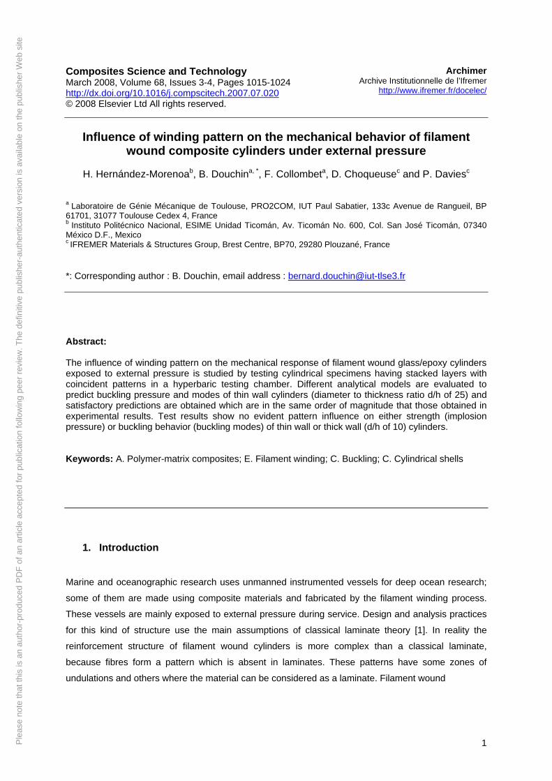
For this type of winding, the machine used is horizontal, normally with three degrees of freedom: axial,
radial and rotation around the central axis (see Figure 1).
Fig. 1. Filament winding machine (LGMT PRO2COM) and its displacements.
4
This type of machine has a carriage which moves in the axial direction and is provided with a roving feed
system [18]. Roving is wound over the mandrel which turns at the same time as the machine spindle.
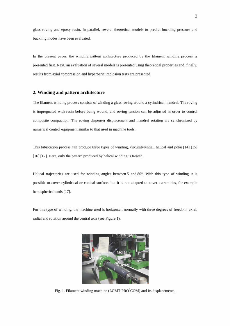
Combined rotational and axial movements produce double helical trajectories and a rhomboid shape
pattern (see Figure 2). When the entire surface is covered, there is, in reality, a double weave ply layer,
equivalent in volume to two unidirectional layers.
Fig. 2. Rhomboid pattern architecture produced by helical winding.
Within each rhomboid, one can distinguish two parts each one comprising half of the rhomboid and
having one edge with a unidirectional layer. Between both parts there is a circumferential undulation zone
where rovings cross over. At each rhomboid side, there is a helical undulation zone. Each rhomboid
constitutes a minimal periodical structure forming the winding pattern, which can be called the unit cell
(see Figure 2). Detailed information about kinematics and its relationship with design and fabrication can
be found in Koussios [2].
3. Specimen characteristics and conditioning
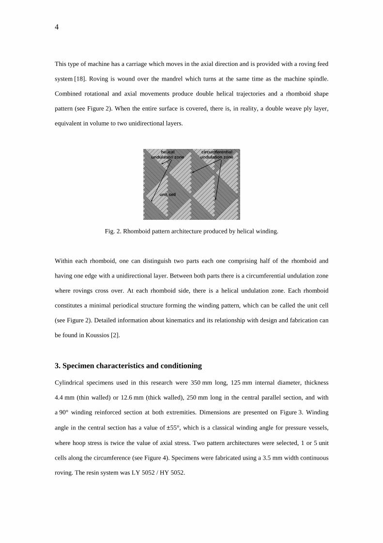
Cylindrical specimens used in this research were 350 mm long, 125 mm internal diameter, thickness
4.4 mm (thin walled) or 12.6 mm (thick walled), 250 mm long in the central parallel section, and with
a 90° winding reinforced section at both extremities. Dimensions are presented on Figure 3. Winding
angle in the central section has a value of ±55°, which is a classical winding angle for pressure vessels,
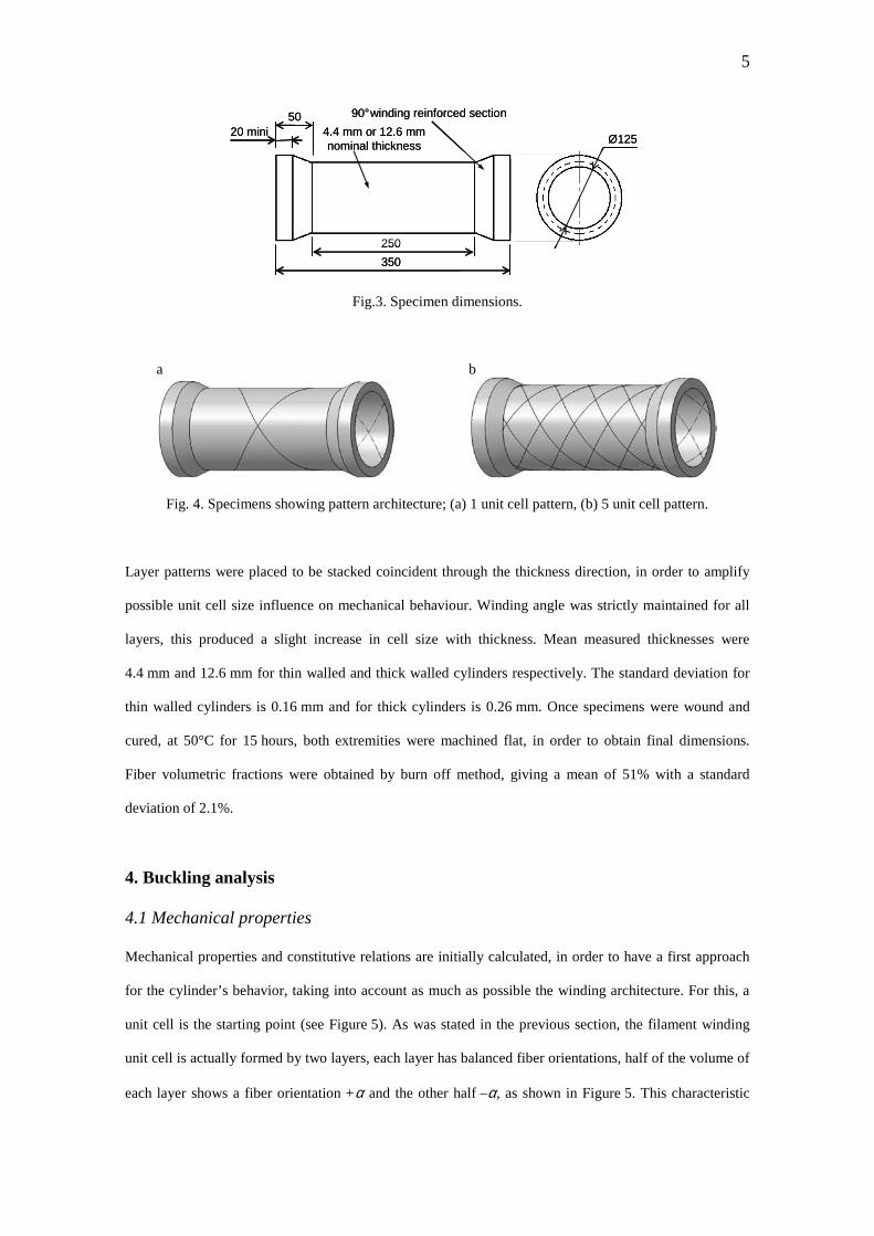
where hoop stress is twice the value of axial stress. Two pattern architectures were selected, 1 or 5 unit
cells along the circumference (see Figure 4). Specimens were fabricated using a 3.5 mm width continuous
roving. The resin system was LY 5052 / HY 5052.
5
Ø125
250
350
20 mini50 90° winding reinforced section
4.4 mm or 12.6 mm nominal thickness Ø125
250
350
20 mini50 90° winding reinforced section
4.4 mm or 12.6 mm nominal thickness
Fig.3. Specimen dimensions.
a b
Fig. 4. Specimens showing pattern architecture; (a) 1 unit cell pattern, (b) 5 unit cell pattern.
Layer patterns were placed to be stacked coincident through the thickness direction, in order to amplify
possible unit cell size influence on mechanical behaviour. Winding angle was strictly maintained for all
layers, this produced a slight increase in cell size with thickness. Mean measured thicknesses were
4.4 mm and 12.6 mm for thin walled and thick walled cylinders respectively. The standard deviation for
thin walled cylinders is 0.16 mm and for thick cylinders is 0.26 mm. Once specimens were wound and
cured, at 50°C for 15 hours, both extremities were machined flat, in order to obtain final dimensions.
Fiber volumetric fractions were obtained by burn off method, giving a mean of 51% with a standard
deviation of 2.1%.
4. Buckling analysis
4.1 Mechanical properties
Mechanical properties and constitutive relations are initially calculated, in order to have a first approach
for the cylinder’s behavior, taking into account as much as possible the winding architecture. For this, a
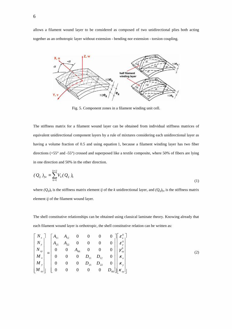
unit cell is the starting point (see Figure 5). As was stated in the previous section, the filament winding
unit cell is actually formed by two layers, each layer has balanced fiber orientations, half of the volume of
each layer shows a fiber orientation +α and the other half –α, as shown in Figure 5. This characteristic
6
allows a filament wound layer to be considered as composed of two unidirectional plies both acting
together as an orthotropic layer without extension - bending nor extension - torsion coupling.
Fig. 5. Component zones in a filament winding unit cell.
The stiffness matrix for a filament wound layer can be obtained from individual stiffness matrices of
equivalent unidirectional component layers by a rule of mixtures considering each unidirectional layer as
having a volume fraction of 0.5 and using equation 1, because a filament winding layer has two fiber
directions (+55° and -55°) crossed and superposed like a textile composite, where 50% of fibers are lying
in one direction and 50% in the other direction.
k
k
kijkfwij )Q(V)Q( ∑
=
=
=2
1 (1)
where (Qij)k is the stiffness matrix element ij of the k unidirectional layer, and (Qij)fw is the stiffness matrix
element ij of the filament wound layer.
The shell constitutive relationships can be obtained using classical laminate theory. Knowing already that
each filament wound layer is orthotropic, the shell constitutive relation can be written as:
=
xy
y
x
xy
y
x
xy
y
x
xy
y
x
D
DD
DD
A
AA
AA
M
M
M
N
N
N
κκκγεε
0
0
0
66
2221
1211
66
2221
1211
00000
0000
0000
00000
0000
0000
(2)
7
where Ni is the force / unit length acting on the shell in the i direction, and Mi is the moment / unit length
acting on the shell in direction i. ε0i is the membrane strain following i direction, and κi is the shell
curvature in the i direction. Elements of the shell stiffness matrix can be obtained using equations 3 and 4:
∑=
=−−=
nk
kfwijkkij )Q)(hh(A
11
(3)
∑=
=−−=
nk
kfwijkkij )Q)(hh(D
1
31
3
3
1
(4)
where hk is the through thickness position of the layer within the laminate, the laminated stacking
sequence is sketched in Figure 6.
Fig. 6. Stacking sequence and layer position.
Table 1
Mechanical properties of unidirectional layer [19]
E1 (MPa) 39000
E2 (MPa) 8600
ν12 0.28
ν21 0.0617
G12 (MPa) 3800
Considering the properties of an unidirectional layer presented in Table 1, taken from reference [19], the
shell constitutive relations can be evaluated numerically, first by obtaining individual stiffness matrices of
each unidirectional layer, applying equation 5, considering that Ei is the Young’s modulus in the i
direction, ν12 and ν21 are the axial and circumferential Poisson ratios respectively and G12 is the shear
8
modulus of the shell, where 1 and 2 are the principal directions in the unidirectional ply. The reference
coordinate system is shown on Figure 7.
Fig. 7. Layer orientation with respect to cylinder coordinates.
−−
−−
=
12
2112
2
2112
212
2112
121
2112
1
12
00
011
011
][
G
EE
EE
Qνννν
ννν
ννν
(5)
Equation 5 is written following principal directions (see Figure 7), so these equations must be
transformed in directions following the composite shell axial and circumferential directions (see Figures 5
and 7). After transformations the stiffness matrix of each individual unidirectional layer can be written as
below, equations 6 and 7:
−−−−
=°=
1005595444990
9544232538706
4990870612673
][)55(θxyQ (6)
=°−=
1005595444990
9544232538706
4990870612673
][)55(θxyQ (7)
Now using equation 1, the filament wound layer stiffness matrix becomes (equation 8):
=1005500
0232538706
0870612673
][ )( fwxyQ (8)
Using the shell stacking sequence and the positions described in Table 2, and equations 3 and 4, the shell
constitutive relation elements (Aij and Dij) are calculated and presented in Table 3.
9
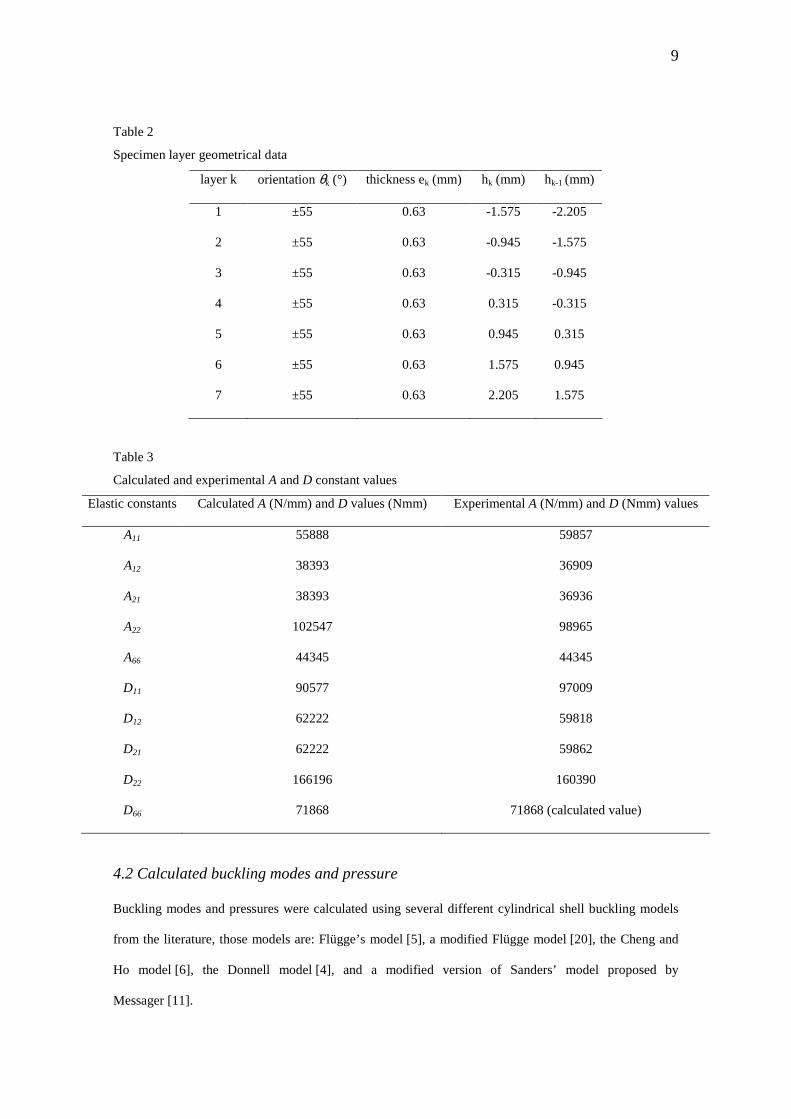
Table 2
Specimen layer geometrical data
layer k orientation θk (°) thickness ek (mm) hk (mm) hk-1 (mm)
1 ±55 0.63 -1.575 -2.205
2 ±55 0.63 -0.945 -1.575
3 ±55 0.63 -0.315 -0.945
4 ±55 0.63 0.315 -0.315
5 ±55 0.63 0.945 0.315
6 ±55 0.63 1.575 0.945
7 ±55 0.63 2.205 1.575
Table 3
Calculated and experimental A and D constant values
Elastic constants Calculated A (N/mm) and D values (Nmm) Experimental A (N/mm) and D (Nmm) values
A11 55888 59857
A12 38393 36909
A21 38393 36936
A22 102547 98965
A66 44345 44345
D11 90577 97009
D12 62222 59818
D21 62222 59862
D22 166196 160390
D66 71868 71868 (calculated value)
4.2 Calculated buckling modes and pressure
Buckling modes and pressures were calculated using several different cylindrical shell buckling models
from the literature, those models are: Flügge’s model [5], a modified Flügge model [20], the Cheng and
Ho model [6], the Donnell model [4], and a modified version of Sanders’ model proposed by
Messager [11].
10
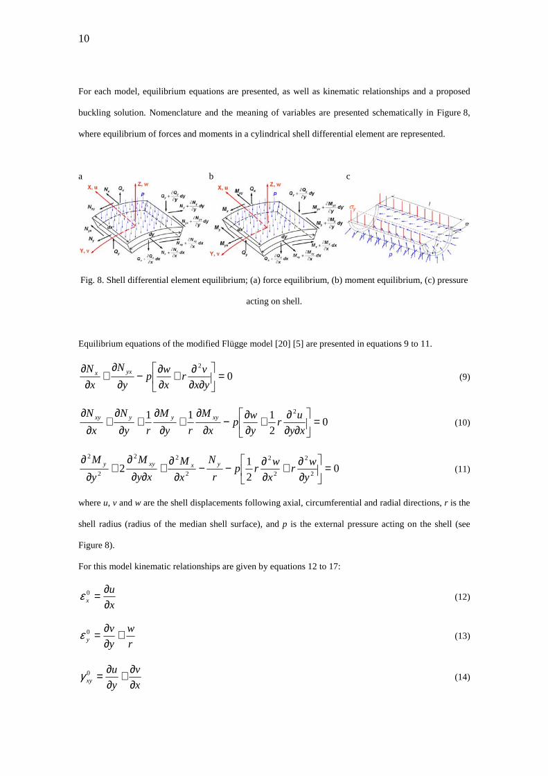
For each model, equilibrium equations are presented, as well as kinematic relationships and a proposed
buckling solution. Nomenclature and the meaning of variables are presented schematically in Figure 8,
where equilibrium of forces and moments in a cylindrical shell differential element are represented.
a b c
Fig. 8. Shell differential element equilibrium; (a) force equilibrium, (b) moment equilibrium, (c) pressure
acting on shell.
Equilibrium equations of the modified Flügge model [20] [5] are presented in equations 9 to 11.
02
=
∂∂∂+
∂∂−
∂∂
+∂
∂yx
vr
x
wp
y
N
x
N yxx (9)
02
111 2
=
∂∂∂+
∂∂−
∂∂
+∂
∂+
∂∂
+∂
∂xy
ur
y
wp
x
M
ry
M
ry
N
x
N xyyyxy (10)
02
12
2
2
2
2
2
22
2
2
=
∂∂+
∂∂−−
∂∂
+∂∂
∂+
∂∂
y
wr
x
wrp
r
N
x
M
xy
M
y
M yxxyy (11)
where u, v and w are the shell displacements following axial, circumferential and radial directions, r is the
shell radius (radius of the median shell surface), and p is the external pressure acting on the shell (see
Figure 8).
For this model kinematic relationships are given by equations 12 to 17:
x
ux ∂
∂=0ε (12)
r
w
y
vy +
∂∂=0ε (13)
x
v
y
uxy ∂
∂+∂∂=0γ (14)
11
2
2
x
wx ∂
∂−=κ (15)
22
2
r
w
y
wy +
∂∂−=κ (16)
x
v
ry
u
ryx
wxy ∂
∂+∂∂−
∂∂∂−= 11
22
κ (17)
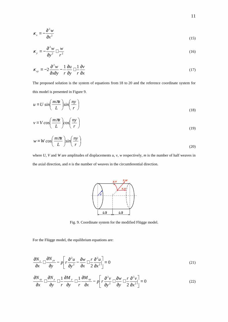
The proposed solution is the system of equations from 18 to 20 and the reference coordinate system for
this model is presented in Figure 9.
=r
nysin
L
xmsinUu
π
(18)
=r
nycos
L
xmcosVv
π
(19)
=r
nysin
L
xmcosWw
π
(20)
where U, V and W are amplitudes of displacements u, v, w respectively, m is the number of half weaves in
the axial direction, and n is the number of weaves in the circumferential direction.
Fig. 9. Coordinate system for the modified Flügge model.
For the Flügge model, the equilibrium equations are:
02 2
2
2
2
=
∂∂+
∂∂−
∂∂−
∂∂
+∂
∂x
ur
x
w
y
urp
y
N
x
N yxx (21)
02
112
2
2
2
=
∂∂+
∂∂+
∂∂−
∂∂
+∂
∂+
∂∂
+∂
∂x
vr
y
w
y
vrp
x
M
ry
M
ry
N
x
N xyyyxy (22)
12
02
22
2
2
2
2
22
2
2
=
∂∂+
∂∂+
∂∂−
∂∂−−
∂∂
+∂∂
∂+
∂∂
x
wr
y
wr
y
v
x
up
r
N
x
M
xy
M
y
M yxxyy (23)
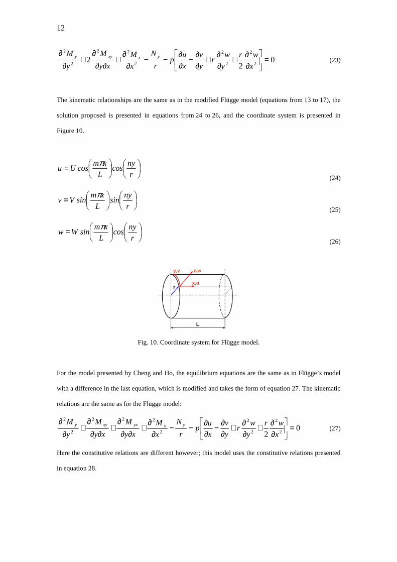
The kinematic relationships are the same as in the modified Flügge model (equations from 13 to 17), the
solution proposed is presented in equations from 24 to 26, and the coordinate system is presented in
Figure 10.
=r
nycos
L
xmcosUu
π
(24)
=r
nysin
L
xmsinVv
π
(25)
=r
nycos
L
xmsinWw
π
(26)
Fig. 10. Coordinate system for Flügge model.
For the model presented by Cheng and Ho, the equilibrium equations are the same as in Flügge’s model
with a difference in the last equation, which is modified and takes the form of equation 27. The kinematic
relations are the same as for the Flügge model:
02 2
2
2
2
2
222
2
2
=
∂∂+
∂∂+
∂∂−
∂∂−−
∂∂
+∂∂
∂+
∂∂∂
+∂
∂x
wr
y
wr
y
v
x
up
r
N
x
M
xy
M
xy
M
y
M yxyxxyy (27)
Here the constitutive relations are different however; this model uses the constitutive relations presented
in equation 28.
13
−+
+
=
xy
y
x
xy
y
x
yx
xy
y
x
yx
xy
y
x
D
Dr
DDD
DDr
D
r
D
r
Dr
D
r
DA
r
D
r
DA
r
DAA
r
DAA
M
M
M
M
N
N
N
N
κκκγεε
0
0
0
66
6666
2212
1211161211
662
6666
662
6666
222212
111211
00000
0000
0000
0
200
200
200
200
000
000
(28)
The proposed solution is given by equations from 29 to 31, with a coordinate system shown in Figure 9.
+=r
ny
L
xmsinAu
π0
(29)
+=r
ny
L
xmsinBv
π0
(30)
+=r
ny
L
xmcosCw
π0
(31)
For Donnell’s model the equilibrium equations are:
02 2
2
2
2
=
∂∂+
∂∂−
∂∂−
∂∂
+∂
∂x
ur
x
w
y
urp
y
N
x
N yxx
(32)
02 2
2
2
2
=
∂∂+
∂∂+
∂∂−
∂∂
+∂
∂x
vr
y
w
y
vrp
y
N
x
N yxy
(33)
02
22
2
2
2
2
22
2
2
=
∂∂+
∂∂+
∂∂−
∂∂−−
∂∂
+∂∂
∂+
∂∂
x
wr
y
wr
y
v
x
up
r
N
x
M
xy
M
y
M yxxyy
(34)
The kinematic relationships are the same as those used in the modified Flügge model (equations from 12
to 17), and the proposed solution is the same as that used in the Cheng and Ho model (equations 29
to 31). The reference coordinate system is presented in Figure 9.
The modified Sanders model used by Messager has the equilibrium equations presented in equations:
14
0=∂
∂+
∂∂
y
N
x
N xyx
(35)
011 =
∂∂−+
∂∂
+∂
∂+
∂∂
+∂
∂y
wrv
r
p
x
M
ry
M
rx
N
y
N xyyxyy
(36)
02
22
2
2
2
2
22
2
2
=
∂∂−
∂∂+
∂∂−−
∂∂
+∂∂
∂+
∂∂
y
v
y
wr
x
wrp
R
N
y
M
yx
M
x
M yyxyx
(37)
The kinematic relations are equations from 12 to 15, and for curvatures y and xy equations are those
referenced by 38 and 39. The solution proposed is formed by equations from 24 to 26, and the coordinate
system used is presented in Figure 10.
y
v
ry
wy ∂
∂+∂∂−= 1
2
2
κ (38)
x
v
ryx
wxy ∂
∂+∂∂
∂−= 22
2
κ (39)
For each model the substitution of proposed solutions into the kinematical relations, and then into
constitutive equations, and finally into the equilibrium equations, gives a system of equations with
3 unknown amplitudes U, V, W and external pressure p. The solution of this equation system for p, gives
an expression depending on shell stiffness constants Aij, Dij, m and n. Aij and Dij are already known. The
critical pressure is obtained by an iterative search using given values for m and n, until finding the
minimum value for p, this p value is the critical pressure and the m and n values represent the longitudinal
and circumferential modes respectively at which critical pressure appears. The calculated values for all
models are presented in Table 4.
Here it can be seen that buckling modes for the specimens studied are m = 1 and n = 3 (one lobe in axial
direction and three lobes around the circumference). A minimum buckling pressure is 6.3 MPa obtained
by Flügge’s model and a maximum buckling pressure of 8 MPa is obtained by Donnell’s model.
15
Table 4
Buckling modes and pressures calculated by theoretical models
Model m n p (MPa)
Modified Flügge model 1 3 6.9
Flügge model 1 3 6.3
Cheng et Ho model 1 3 6.3
Donnell model 1 3 8
Messager model 1 3 6.9
5. Experimental results
Fig. 11. Hyperbaric chamber (IFREMER Brest).
External pressure tests (13 tests in total) were carried out in a hyperbaric testing chamber (see Figure 11)
at the IFREMER facilities in Brest. Four specimens (references 05VE5CNNI-22, 05VE1CNNI-25,
15VE1CNNI-29 and 15VE5CNNI-30) were instrumented with strain gages; four gages placed in the axial
direction and four placed around the circumference, at mid-length on the inner wall. An angular
separation of 45° was specified between consecutive gages, alternating axial and circumferential.
Instrumented specimens were tested in axial compression under a small load (25 kN for thin walled
cylinders and 100 kN for thick walled cylinders), on a 20 ton capacity test frame before pressure testing,
in order to obtain axial mechanical material properties and to check that gages were functioning properly.
The nomenclature chosen to describe specimens gives important information, and the meaning is as
follows: The first two digits 05 or 15 (5mm or 15mm) indicate the nominal thickness of the specimen
which actually is 4.4mm or 12.6mm. The third and fourth characters indicate the composite, in this case
16
VE means glass-epoxy composite. The fifth character (1 or 5) indicates the number of cells along the
circumference. The sixth and seventh characters (CN) mean a normal curing cycle. The eighth and tenth
characters indicate if specimens were instrumented with optical sensors or not (II or NI), in this cases all
tested specimens were not instrumented (NI). The last two digits indicate a consecutive fabrication
number.
For thin walled cylinders, it was assumed a uniform stress distribution along the thickness. Thick walled
cylinders were exposed to same mechanical testing; gages were placed in the same positions as the thin
walled ones, their experimental data was treated in the same way as the data for thin cylinders, and it was
observed almost the same values for mechanical properties. So it was inferred that even if along the
thickness of thick cylinders stress distribution is not uniform, for the dimensions of the thick cylinders
used here, this stress variation along the thickness was not important, and could be neglected only to
obtain mechanical properties in the elastic region, and assuming that the fiber fraction is almost the same
in both cases (thin and thick cylinders).
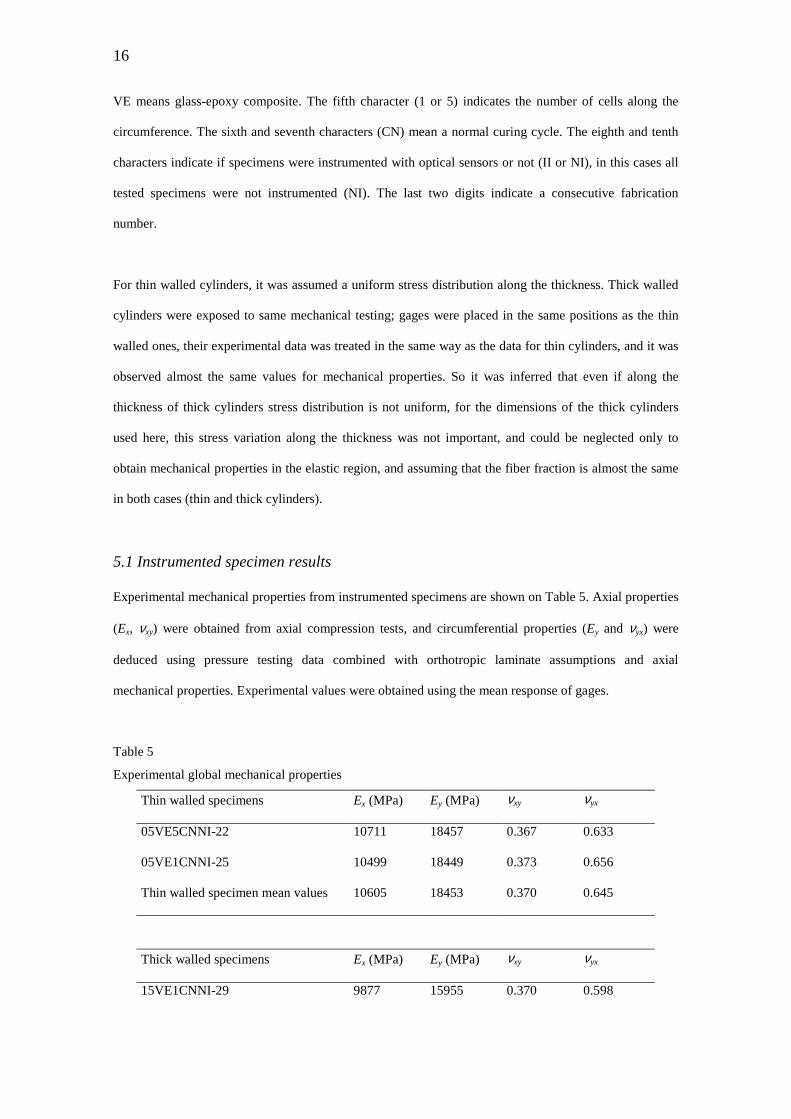
5.1 Instrumented specimen results
Experimental mechanical properties from instrumented specimens are shown on Table 5. Axial properties
(Ex, νxy) were obtained from axial compression tests, and circumferential properties (Ey and νyx) were
deduced using pressure testing data combined with orthotropic laminate assumptions and axial
mechanical properties. Experimental values were obtained using the mean response of gages.
Table 5
Experimental global mechanical properties
Thin walled specimens Ex (MPa) Ey (MPa) νxy νyx
05VE5CNNI-22 10711 18457 0.367 0.633
05VE1CNNI-25 10499 18449 0.373 0.656
Thin walled specimen mean values 10605 18453 0.370 0.645
Thick walled specimens Ex (MPa) Ey (MPa) νxy νyx
15VE1CNNI-29 9877 15955 0.370 0.598
17
15VE5CNNI-30 10711 16245 0.382 0.579
Thick walled specimen mean values 10294 16100 0.376 0.589
Ex (MPa) Ey (MPa) νxy νyx
Global mean values 10449 17277 0.373 0.617
With experimental mechanical properties (Table 5) A and D constants were calculated (experimental
values), and results are shown in Table 3. The difference between experimental and calculated values is
very small, in the range from 4 to 7 %.
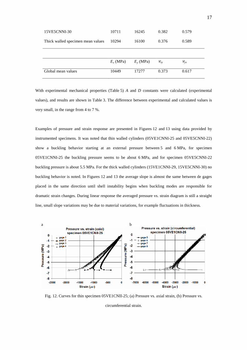
Examples of pressure and strain response are presented in Figures 12 and 13 using data provided by
instrumented specimens. It was noted that thin walled cylinders (05VE1CNNI-25 and 05VE5CNNI-22)
show a buckling behavior starting at an external pressure between 5 and 6 MPa, for specimen
05VE1CNNI-25 the buckling pressure seems to be about 6 MPa, and for specimen 05VE5CNNI-22
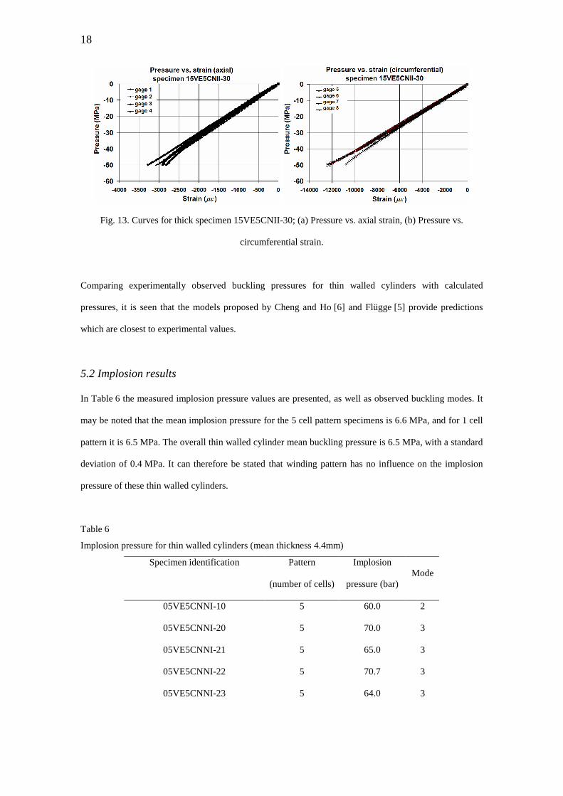
buckling pressure is about 5.5 MPa. For the thick walled cylinders (15VE1CNNI-29, 15VE5CNNI-30) no
buckling behavior is noted. In Figures 12 and 13 the average slope is almost the same between de gages
placed in the same direction until shell instability begins when buckling modes are responsible for
dramatic strain changes. During linear response the averaged pressure vs. strain diagram is still a straight
line, small slope variations may be due to material variations, for example fluctuations in thickness.
a b
Fig. 12. Curves for thin specimen 05VE1CNII-25; (a) Pressure vs. axial strain, (b) Pressure vs.
circumferential strain.
18
Fig. 13. Curves for thick specimen 15VE5CNII-30; (a) Pressure vs. axial strain, (b) Pressure vs.
circumferential strain.
Comparing experimentally observed buckling pressures for thin walled cylinders with calculated
pressures, it is seen that the models proposed by Cheng and Ho [6] and Flügge [5] provide predictions
which are closest to experimental values.
5.2 Implosion results
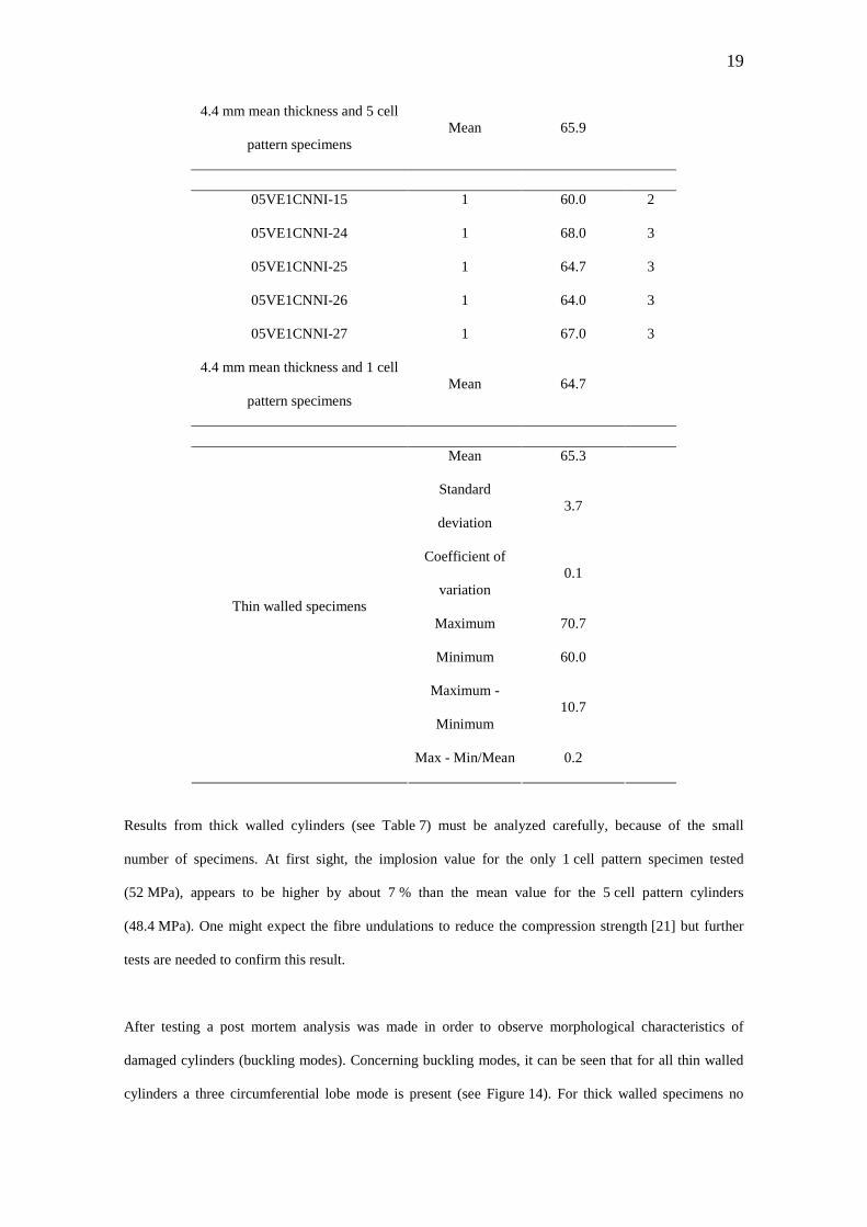
In Table 6 the measured implosion pressure values are presented, as well as observed buckling modes. It
may be noted that the mean implosion pressure for the 5 cell pattern specimens is 6.6 MPa, and for 1 cell
pattern it is 6.5 MPa. The overall thin walled cylinder mean buckling pressure is 6.5 MPa, with a standard
deviation of 0.4 MPa. It can therefore be stated that winding pattern has no influence on the implosion
pressure of these thin walled cylinders.
Table 6
Implosion pressure for thin walled cylinders (mean thickness 4.4mm)
Specimen identification
Pattern
(number of cells)
Implosion
pressure (bar) Mode
05VE5CNNI-10 5 60.0 2
05VE5CNNI-20 5 70.0 3
05VE5CNNI-21 5 65.0 3
05VE5CNNI-22 5 70.7 3
05VE5CNNI-23 5 64.0 3
19
4.4 mm mean thickness and 5 cell
pattern specimens Mean 65.9
05VE1CNNI-15 1 60.0 2
05VE1CNNI-24 1 68.0 3
05VE1CNNI-25 1 64.7 3
05VE1CNNI-26 1 64.0 3
05VE1CNNI-27 1 67.0 3
4.4 mm mean thickness and 1 cell
pattern specimens Mean 64.7
Mean 65.3
Standard
deviation 3.7
Coefficient of
variation 0.1
Maximum 70.7
Minimum 60.0
Maximum -
Minimum 10.7
Thin walled specimens
Max - Min/Mean 0.2
Results from thick walled cylinders (see Table 7) must be analyzed carefully, because of the small
number of specimens. At first sight, the implosion value for the only 1 cell pattern specimen tested
(52 MPa), appears to be higher by about 7 % than the mean value for the 5 cell pattern cylinders
(48.4 MPa). One might expect the fibre undulations to reduce the compression strength [21] but further
tests are needed to confirm this result.
After testing a post mortem analysis was made in order to observe morphological characteristics of
damaged cylinders (buckling modes). Concerning buckling modes, it can be seen that for all thin walled
cylinders a three circumferential lobe mode is present (see Figure 14). For thick walled specimens no
20
clear buckled shape is noted although the fracture pattern might suggest a mode 2 failure in the
circumferential direction and mode 1 in the longitudinal direction (see Figure 15).
Table 7
Implosion pressure for thick walled cylinders (mean thickness 12.6 mm)
Specimen identification
Pattern
(number of cells)
Implosion
pressure (bar) Mode
15VE1CNNI-29 1 520.6 2
15VE5CNNI-30 5 500.8 2
15VE5CNNI-31 5 467.0 2
12.6 mm mean thickness and
5 cell pattern specimens Mean 483.9
Mean 496.1
Maximum 520.6 Thick walled specimens
Minimum 467
a b c
Fig. 14. Damaged thin walled specimen after implosion, showing buckling modes with mode one axial
and mode 3 circumferential; (a) schematic view, (b) and (c) views of a buckled tube.
Calculated buckling modes from all models give the same result (see Table 4), m = 1 and n = 3, one lobe
axial and three lobes in circumferential direction, this agrees with experimentally observed buckling
modes (see Table 6, and Figure 14).
21
a b
Fig. 15. Damaged thick walled specimens; (a) 1 unit cell pattern, (b) 5 unit cell pattern.
6. Conclusions
Results from this study show no strong influence of the two chosen winding patterns on the implosion
pressure of filament wound composite cylinders. Buckling behavior does not seem to be sensitive to these
two winding patterns. Buckling modes for specimen dimensions and characteristics used in this research
are all of the m = 1 and n = 3 type, independent of winding pattern. Surface damage morphology of thick
walled cylinders is not influenced by winding pattern. The choice of 1 and 5 unit cells along the
circumference of cylindrical specimens is made, between several possibilities, for represent extreme cases
(degree of undulation minimum or very high). Moreover, the coincidence of the unit cells through the
thickness direction would have amplified the influence, if it had existed, of the unit cell size on
mechanical behavior. For all that, if there is no clear influence of the winding pattern on implosion
pressure and buckling behavior, we can think that this parameter don’t have a major role in the resistance
of filament wound cylinders under external pressure. All theoretical models predicted axial mode one
(m = 1) and circumferential mode three (n = 3), which corresponds exactly to experimentally observed
buckling modes. Buckling pressure evaluated using the Flügge [5] and Cheng and Ho models [6]
provided the closest critical pressure predictions to the experimental buckling pressure. The different
presented buckling behaviors of tubular structures depend on their thickness, but other geometrical
parameters (different length-diameter ratios, etc) could have of course a direct influence on the buckling
response too.
22
Acknowledgments
Hilario Hernández Moreno wishes to thank the National Council of Science and Technology of Mexico
(CONACYT) and the National Polytechnic Institute of Mexico (IPN) for their scholarship sponsoring.
The authors thank Mrs. Ivan Fernandez Hernandez, Jérémie Bauw, Felipe Afonso, and Erik Vargas Rojas
for their collaboration during their internship at LGMT/PRO2COM. Also many thanks to Mr. Matthieu
Mulle, PhD at LGMT/PRO2COM, for his collaboration during the instrumented implosion test, and
IFREMER for its financial and technical support, with special thanks to Philippe Warnier and Albert
Deuff.
References
1. Hoa SV. Analysis for design of fiber reinforced plastic vessels and piping. Technomic Publication:
Lancaster, 1991.
2. Koussios S, Filament Winding: a Unified Approach, PhD Thesis, Delft University Press, Delft, 2004.
p 1-300.
3. Zhao L,. Mantell SC, Cohen D, McPeak R, Finite element modeling of the filament winding process,
Composite Structures, 2001, Vol. 52(3-4), p. 499-510.
4. Donnell LH. Stability of thin-walled tubes under torsion. NACA report No. 479, 1933. p. 95-116.
5. Flügge W. Stress in shells, 2nd edition. Springer-Verlag Berlin Heidelberg NewYork, 1973.
p. 103-112, 204-217, 439-452.
6. Cheng S, Ho BPC. Stability of heterogeneous anisotropic cylindrical shells under combined loading.
AIAA Journal, Vol. 1, 1963. p. 892-898.
7. Peterson JP, Seide P, Weingarten VI. Buckling of thin-walled circular cylinders. NASA SP 8007, 1968.
p. 13-40.
8. Smitses G. Buckilng of moderately thick laminated cylindrical shells, a review. Composites: Part B,
Vol. 27, 1996. p. 581-587.
9. Fuchs JP, Hyer MW, Starnes JH Jr. Numerical and experimental investigation of bending response of
thin-walled composite cylinders. NASA CR 195730. Blacksburg, 1993.
10. Hahn HT, Jensen DW, Claus SJ, Pai SP, Hipp PA. Structural design criteria for filament-wound
composite shells. NASA CR 195125, 1994.
23
11. Messager T. Buckling of imperfect laminated cylinders under hydrostatic pressure. Composite
Structures, Vol. 53, 2001. p. 301-307.
12. Elghazouli AY, Chryssanthopoulos MK, Spagnoli A. Experimental response of glass-reinforced
plastic cylinders under axial compression. Marine Structures, Vol. 11, 1998. p. 347–371.
13. Carvelli V, Panzeri N, Poggi C. Buckling strength of GFRP under-water vehicles. Composites:
Part B, Vol. 32, 2001. p. 89-101.
14. Lowe A. Lecture notes for ENGN4511. Composite materials, Department of Engineering, Australian
National University, Camberra, 2001. p. 52-53.
15. Lye SW, Boey FYC. Development of a low-cost prototype filament-winding system for composite
components. Journal of Materials Processing Technology, Vol. 52, 1995. p. 570-584.
16. Berthelot JM. Matériaux composites. Tec & Doc, Paris, 1994. p. 63-67.
17. Shen FC. A filament-wound structure technology overview. Materials Chemistry and Physics,
Vol. 42(2), 1995. p. 96-100.
18. International standard ISO 1268-5: 2001, Plastiques renforcés de fibre – Méthodes de fabrication de
plaques d’essai - Partie 5: Moulage par enroulement filamentaire, première édition. Organisation
Internationale de Normalisation. Genève, 2001.
19. Daniel IM, Ishai O. Engineering mechanics of composite materials. Oxford University Press, 1994.
20. Hernandez-Moreno H. Monitoring de la fabrication de tubes composites réalisés par enroulement
filamentaire et comportement mécanique sous pression externe. PhD Thesis, Université Paul Sabatier (in
French), 2006, p. 1-238.
21. Hsiao HM, Daniel IM. Effect of fiber waviness on stiffness and strength reduction of unidirectional
composites under compressive loading. Composites Science and Technology, 1996, Vol. 56(5),