BHM 11/21/17 NTV-DOC243 Agreement: End user agrees to use this product in compliance with all State and Federal laws. NAV-TV Corp. would not be held liable for misuse of its product. If you do not agree, please discontinue use immediately and return product to place of purchase. This product is intended for off-road use and passenger entertainment only. 1 | Page 3950 NW 120 th Ave, Coral Springs, FL 33065 TEL 561-955-9770 FAX 561-955-9760 www.nav-tv.com [email protected]AUDI DYNAMIC-EXT NTV-KIT701 Overview The AUDI-DYN EXT Kit interfaces a backup camera (with dynamic guidelines) and one additional video input (front cam, etc) to the factory media screen in select Audi vehicles with the external MMi media system (MMi controls on the console, not vertical radio face). Kit Content Power/CAN Harness A-Type LVDS-IN Cable AUDI-DYN EXT Interface OSD Menu Remote IR-Eye Cable HD-LINK Optional KIT800
Transcript
BHM 11/21/17
NTV-DOC243
Agreement: End user agrees to use this product in compliance with all State and Federal laws. NAV-TV Corp. would not be held liable for
misuse of its product. If you do not agree, please discontinue use immediately and return product to place of purchase. This product is intended for off-road use and passenger entertainment only.
1 | P a g e
3950 NW 120th Ave, Coral Springs, FL 33065 TEL 561-955-9770 FAX 561-955-9760
The AUDI-DYN EXT Kit interfaces a backup camera (with dynamic guidelines) and one additional video input (front cam, etc) to the factory media screen in select Audi vehicles with the external MMi media system (MMi controls on the console, not vertical radio face).
Agreement: End user agrees to use this product in compliance with all State and Federal laws. NAV-TV Corp. would not be held liable for
misuse of its product. If you do not agree, please discontinue use immediately and return product to place of purchase. This product is intended for off-road use and passenger entertainment only.
2 | P a g e
Interface Connectors
Dip Switch Settings
Dip SW: 1 2 3 4 5 6 7 8
UP AUX MENU OFF (leave UP normally)
CAN TYPE
CAN TYPE
RVC OFF CAN SPEED 1
N/A HI RES KEEP DOWN
DOWN AUX MENU ON (leave UP normally)
CAN TYPE
CAN TYPE
RVC ON CAN SPEED 2
N/A LOW RES KEEP DOWN
YEAR VEHICLE 1 2 3 4 5 6 7 8
Up to 2010
A4, A5, A6, Q5
X X RVC OFF X N/A HIGH RES
X RVC ON N/A LOW RES X
2011+
A4, A5, Q5 X X X RVC OFF X N/A HIGH RES
RVC ON N/A LOW RES X
Up to 2010
Q7 X X RVC OFF X N/A HIGH RES
X RVC ON N/A LOW RES X
2011+
Q3, Q7 X RVC OFF N/A HIGH RES
X X RVC ON X N/A LOW RES X
2011+ A6, Touareg, Lamborghini
X X X RVC OFF N/A HIGH RES
RVC ON X N/A LOW RES X
Note: You must remove power to the unit prior to
making adjustments to the dip switches.
Power/CAN
OUOUT
Dip Switches HDMI Cable from HD-LINK Expansion Board Control
LVDS Video IN
OUOUT
Not Used
LVDS Video OUT RGB IN
Not Used
BHM 11/21/17
NTV-DOC243
Agreement: End user agrees to use this product in compliance with all State and Federal laws. NAV-TV Corp. would not be held liable for
misuse of its product. If you do not agree, please discontinue use immediately and return product to place of purchase. This product is intended for off-road use and passenger entertainment only.
3 | P a g e
AUDI-DYN-EXT Installation (A4, A5, A6, Q5)
1. Remove the factory radio (CD). Depending on the vehicle, this will require EURO tools or
just prying the climate control panel from the sides (use plastic tools!). Disconnect all
harnesses and set the radio aside.
2. Remove/drop the glovebox. This requires removing multiple
8mm bolts which secure it to the dash. In some vehicles the
pocket or single DIN media-gateway must be removed to
access a bolt for removal.
a. Remove this beauty panel before dropping glove box
(newer AUDI’s, beneath glove box):
3. Connect the provided LVDS-IN Cable to the
OEM radio at the pink connector (no nav) or
gray connector (with nav). This connector is
keyed and will only fit in one direction. Run
the other end of this cable out to the glove
box area and connect to the interface plug
labeled ‘VIDEO IN’.
4. Connect the OEM pink (or gray) circular HSD connector previously connected to the
radio (removed in step 1) to the green port on
the interface labeled ‘VIDEO OUT’. You may
need to unwrap/cut factory tape for it reach
the module with proper slack.
5. Reconnect remaining plugs to the radio and carefully place it back into the dash. Don’t
secure the radio until fully tested.
6. Optional: If this car is not equipped with OEM rear parking sensors, you may turn the
PDC off in the OSD menu system (see page 7 for menu information).
Note: If adjusting any RVC or AUX Video menu settings, temporarily connecting the
provided IR-Eye is required. The IR connector is located among the main power harness (2-pin
& 3-pin). See menu settings on page 7 for more info.
ATTENTION INSTALLER: All connections (including CAN) must be made BEFORE
connecting the power harness to this unit for proper startup operation.
BHM 11/21/17
NTV-DOC243
Agreement: End user agrees to use this product in compliance with all State and Federal laws. NAV-TV Corp. would not be held liable for
misuse of its product. If you do not agree, please discontinue use immediately and return product to place of purchase. This product is intended for off-road use and passenger entertainment only.
4 | P a g e
7. Grab the provided Power/CAN Harness from the AUDI-DYN-
EXT kit. Use the chart below to locate and solder (splice,
don’t cut) the following wires to the car (you may have to
extend a pair of CAN wires for Q7):
AUDI A4, A5, Q5 CAN Wires Location
Vehicle Interface wires Connect to AUDI Wire: Wire Location
ALL GROUND (Black) Brown (-) Can Gateway or Radio
POWER (Red) Black/White (ACC +) Passenger side fuse box (extend)
A4/A5/ Q5
CAN HI (Blue)
CAN HI (Orange/Green) CAN Gateway (Right side of radio.
Must remove glove box for access.)
CAN LO (White)
CAN LO (Orange/Brown) CAN Gateway (Right side of radio.
Must remove glove box for access.)
A6 or
Lamborghini*
CAN HI (Blue)
CAN HI (Orange/Blue) Climate Control (Beneath radio)
CAN LO (White)
CAN LO (Orange/Brown) Climate Control (Beneath radio)
Q3/Q7
CAN HI (Blue)
CAN HI (Orange/Black) CAN Gateway (High in drivers dash to
the left of steering wheel)
CAN LO (White) CAN LO (Orange/Brown
with blue dots) CAN Gateway (High in drivers dash to
the left of steering wheel)
VW Touareg
CAN HI (Blue)
CAN HI (Orange/Green) CAN Gateway (High in drivers dash to
the left of steering wheel)
CAN LO (White)
CAN LO (Orange/Brown) CAN Gateway (High in drivers dash to
the left of steering wheel)
CAN Gateway
With
MOST
Fiber
CAN Gateway location (A4, A5, Q5)
*For Lamborghini, the CAN wires may need to be extended to reach the climate control module.
BHM 11/21/17
NTV-DOC243
Agreement: End user agrees to use this product in compliance with all State and Federal laws. NAV-TV Corp. would not be held liable for
misuse of its product. If you do not agree, please discontinue use immediately and return product to place of purchase. This product is intended for off-road use and passenger entertainment only.
5 | P a g e
8. Install your reverse camera and run signal, power and ground wires up front to the AUDI
interface.
9. Power your camera with an ACC source, not a reverse lamp trigger (the purple wire
from the main power harness labeled ‘REAR12VOUT’ provides 12v (+) when in reverese
only, if you want to use a reverse signal).
10. Connect the signal for your camera to the yellow RCA among the Power/CAN Harness
labeled ‘CAMERA’.
11. Optional: If adding an auxillary video in or front camera, connect the signal to the RCA
among the Power/CAN Harness labeled ‘CVBSIN’. If automatic front camera switching is
desired, the setting must be activated in the OSD Menu system. See page 8.
12. Connect the 24-pin white plug from the Power/CAN Harness to the port on the AUDI 09
interface labeled ‘Power/CAN’.
13. UPDATE: For older AUDI’s (only) that do not have the ‘iNAV’ button on the steering
wheel and adding AUX Video/Front Camera, connect (solder) the White wire labeled
‘MMI’ to the MMI data wire located behind the OEM radio at the Euro-style plug, at pin
10. This wire color will vary by vehicle, but the pin location will remain the same.
Press the NAV button near the MMi command knob for switching to the AUX
video/front camera source at any time.
14. Start the car and test for proper functionality before replacing dash pieces. If menu
adjustments are needed (to remove sensor overlay, etc.), proceed to ‘Menu
Adjustments’
Wire side view
BHM 11/21/17
NTV-DOC243
Agreement: End user agrees to use this product in compliance with all State and Federal laws. NAV-TV Corp. would not be held liable for
misuse of its product. If you do not agree, please discontinue use immediately and return product to place of purchase. This product is intended for off-road use and passenger entertainment only.
6 | P a g e
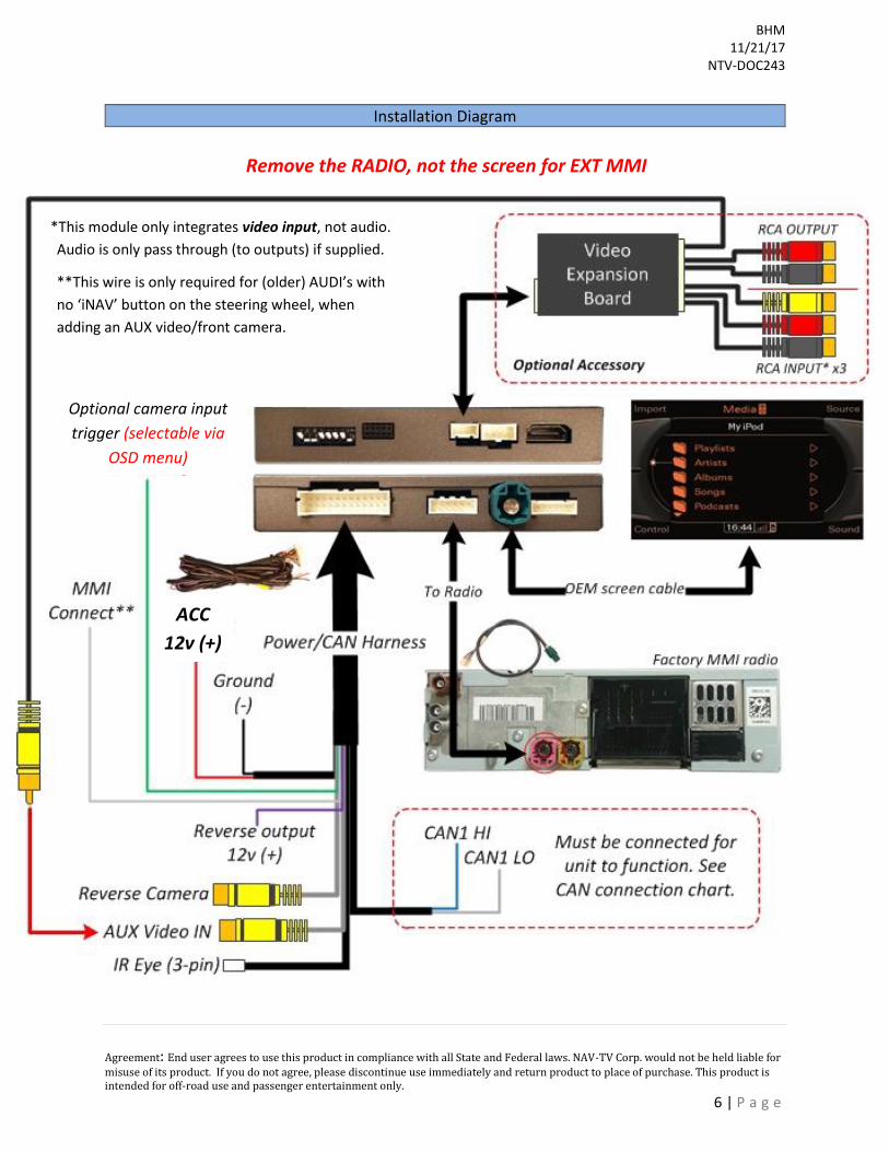
Installation Diagram
*This module only integrates video input, not audio.
Audio is only pass through (to outputs) if supplied.
Remove the RADIO, not the screen for EXT MMI
**This wire is only required for (older) AUDI’s with
no ‘iNAV’ button on the steering wheel, when
adding an AUX video/front camera.
ACC
12v (+)
Optional camera input
trigger (selectable via
OSD menu)
BHM 11/21/17
NTV-DOC243
Agreement: End user agrees to use this product in compliance with all State and Federal laws. NAV-TV Corp. would not be held liable for
misuse of its product. If you do not agree, please discontinue use immediately and return product to place of purchase. This product is intended for off-road use and passenger entertainment only.
7 | P a g e
If adding a front camera OR Aux Video source:
1. Disconnect POWER/CAN Harness from interface
2. Place DIP SWITCH 1 in the DOWN position, reconnect power
3. Press the iNAV button on the steering wheel to activate ‘NAV input’
4. Press OK button on remote 4 times, then press POWER
SET – FRON CAM must be turned on if adding a front camera and the user
wishes for automatic front camera switching. Options for 5, 7, 9 or 11
seconds are user-selectable for the length of time the front camera input
stays active once the vehicle is placed out of reverse.
If the user wants only an AUX video input without front camera, set AV1-
SEL to ON
Once finished with settings, place DIP SWITCH 1 back into the UP position
and reset power to interface.
Menu Adjustments
Before you start:
1. The IR-Eye must be connected 2. Make sure the car’s ignition is on and radio is on 3. You must be in Reverse Camera mode OR AUX Video mode (see
below):
• Reverse Camera Mode adjusts Reverse Camera Settings
• AUX Video Mode adjusts AUX Video Settings 4. Press the OK BUTTON 4 times (numbers will display per press),
then press POWER. 5. The OSD Menu will appear on screen (auto-time out in about 5
seconds if no action occurs).
Functional Parking Guidelines ON/OFF
Parking Distance Control ON/OFF (while in reverse)
Adjust FPG Position
Adjust PDC Position
‘Safe to move?’ ON/OFF
PDC
Return (AUX VID
menu control)
RVC Menu
AUX VIDEO Menu
BHM 11/21/17
NTV-DOC243
Agreement: End user agrees to use this product in compliance with all State and Federal laws. NAV-TV Corp. would not be held liable for
misuse of its product. If you do not agree, please discontinue use immediately and return product to place of purchase. This product is intended for off-road use and passenger entertainment only.
8 | P a g e
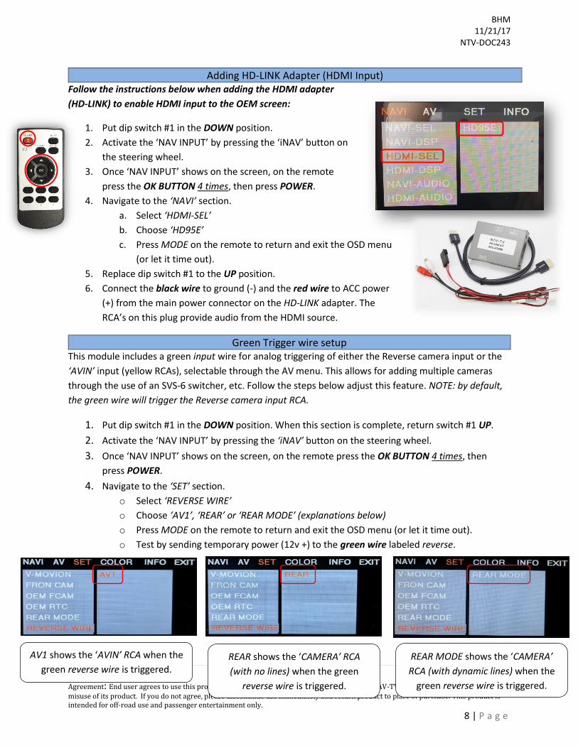
Adding HD-LINK Adapter (HDMI Input) Follow the instructions below when adding the HDMI adapter
(HD-LINK) to enable HDMI input to the OEM screen:
1. Put dip switch #1 in the DOWN position.
2. Activate the ‘NAV INPUT’ by pressing the ‘iNAV’ button on
the steering wheel.
3. Once ‘NAV INPUT’ shows on the screen, on the remote
press the OK BUTTON 4 times, then press POWER.
4. Navigate to the ‘NAVI’ section.
a. Select ‘HDMI-SEL’
b. Choose ‘HD95E’
c. Press MODE on the remote to return and exit the OSD menu
(or let it time out).
5. Replace dip switch #1 to the UP position.
6. Connect the black wire to ground (-) and the red wire to ACC power
(+) from the main power connector on the HD-LINK adapter. The
RCA’s on this plug provide audio from the HDMI source.
Green Trigger wire setup This module includes a green input wire for analog triggering of either the Reverse camera input or the
‘AVIN’ input (yellow RCAs), selectable through the AV menu. This allows for adding multiple cameras
through the use of an SVS-6 switcher, etc. Follow the steps below adjust this feature. NOTE: by default,
the green wire will trigger the Reverse camera input RCA.
1. Put dip switch #1 in the DOWN position. When this section is complete, return switch #1 UP.
2. Activate the ‘NAV INPUT’ by pressing the ‘iNAV’ button on the steering wheel.
3. Once ‘NAV INPUT’ shows on the screen, on the remote press the OK BUTTON 4 times, then
press POWER.
4. Navigate to the ‘SET’ section.
o Select ‘REVERSE WIRE’
o Choose ‘AV1’, ‘REAR’ or ‘REAR MODE’ (explanations below)
o Press MODE on the remote to return and exit the OSD menu (or let it time out).
o Test by sending temporary power (12v +) to the green wire labeled reverse.
AV1 shows the ‘AVIN’ RCA when the
green reverse wire is triggered. REAR MODE shows the ‘CAMERA’
RCA (with dynamic lines) when the
green reverse wire is triggered.
REAR shows the ‘CAMERA’ RCA
(with no lines) when the green
reverse wire is triggered.
BHM 11/21/17
NTV-DOC243
Agreement: End user agrees to use this product in compliance with all State and Federal laws. NAV-TV Corp. would not be held liable for
misuse of its product. If you do not agree, please discontinue use immediately and return product to place of purchase. This product is intended for off-road use and passenger entertainment only.
9 | P a g e
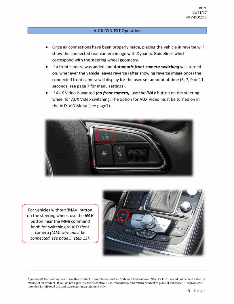
AUDI DYN-EXT Operation
• Once all connections have been properly made, placing the vehicle in reverse will
show the connected rear camera image with Dynamic Guidelines which
correspond with the steering wheel geometry.
• If a front camera was added and Automatic front-camera switching was turned
on, whenever the vehicle leaves reverse (after showing reverse image once) the
connected front camera will display for the user-set amount of time (5, 7, 9 or 11
seconds, see page 7 for menu settings).
• If AUX Video is wanted (no front camera), use the iNAV button on the steering
wheel for AUX Video switching. The option for AUX Video must be turned on in
the AUX VID Menu (see page7).
For vehicles without ‘iNAV’ button on the steering wheel, use the NAV
button near the MMi command knob for switching to AUX/font
camera (MMi wire must be connected, see page 5, step 13).
BHM 11/21/17
NTV-DOC243
Agreement: End user agrees to use this product in compliance with all State and Federal laws. NAV-TV Corp. would not be held liable for
misuse of its product. If you do not agree, please discontinue use immediately and return product to place of purchase. This product is intended for off-road use and passenger entertainment only.
10 | P a g e
FAQs
Q. The unit will not power on, I have no indication of proper operation.
A. This module will not power on properly or display anything (reverse image or AUX video IN) until CAN is properly connected. Q. All I see on the display is a black screen (no factory image pass-through).
A. Verify the video cables (IN/OUT) are connected at the proper location (at the radio). B. Verify you’re using the correct LVDS video connector (pink or gray). C. Verify Dip Switches are set correctly.
Q. Nothing happens on the media screen when I place the vehicle in reverse. A. Make sure DIP Switch 4 is the DOWN position (pull power from the interface first!). If
still nothing, try placing DIP Switch 5 in the opposite position (pull power from the interface first!). Also, DIP Switch 8 must be DOWN, always.
B. Try a different year setting (with same model) from the Dip Switch chart. C. Verify 12v (+) and ground to the interface.
Q. Rear camera image does NOT appear.
A. Verify Dip Switch #4 in set down for aftermarket camera, or up for a factory camera. B. Verify the CAN wires and location of CAN connection. C. Make certain the camera is properly powered. Check voltage at the camera itself. D. Try an alternative video source, don’t assume the power/ground is correct unless
you’ve checked it with a multi-meter! E. If this is a CAN-connected module and you’ve connected the CAN wires, try using the
green wire instead of the CAN connection for reverse activation. Q. Unwanted A/V mode is displayed upon a toggle press (A/V source switching order: OEM->RGB->AV1->AV2->OEM).