– Enhanced Flash memory• 2 Seconds Programming Time
• Low Cost MPLAB-ICD-II Support
• Flexible Program Memory Protection
• Data Memory addressing to 4KB
2
Informatica Industriale
Lezione 2 3
Device Structure
Ogni parte del dispositivo può essere collocata
all’interno di questi gruppi
•Core
•Peripherals
•Special Features
Informatica Industriale
Lezione 2 4
Per Core si intende l’insieme di elementi che rendono il dispositivo operativo:
» Oscillator
» Reset
» Architecture
» CPU (Central Processing Unit)
» ALU (Arithmetic Logical Unit)
» Hardware 8x8 Multiplier
» Memory
» Table Read / Table Write
» System Bus
» Interrupts
» Instruction Set
Device Structure: Core
3
Informatica Industriale
Lezione 2 5
Device Structure:
Peripherals• Per Periferiche si intende l’insieme di componenti
che permette una caratterizzazione del dispositivo
» I/O
» Parallel Slave Port (PSP)
» Timer
» Capture/Compare/PWM (CCP)
» Serial Slave Port (SSP)
» Master Synchronous Serial Port (MSSP)
» Addressable USART
» CAN
» Comparator Voltage Reference
» 10-bit A/D Converter
Informatica Industriale
Lezione 2 6
» Oscillator
» Reset
» Architecture
» CPU (Central Processing Unit) and System Bus
» ALU (Arithmetic Logical Unit)
» Hardware 8x8 Multiplier
» Memory Map
» Table Read / Table Write
» Interrupts
» Instruction Set
Device Structure: Core
4
Informatica Industriale
Lezione 2 7
ResetIl Reset serve per riportare il dispositivo ad uno stato
conosciuto
TIPI DI RESET
• Power-on Reset (POR)
• MCLR Reset during normal operation
• MCLR Reset during SLEEP
• WDT Reset (normal operation)
• Programmable Brown-out Reset (BOR)
• RESET Instruction
• Stack Overflow Reset
• Stack Underflow Reset
Informatica Industriale
Lezione 2 8
Reset Control (RCON) register
• RI: Reset Instruction Flag bit
• TO: Watchdog Time-out Flag bit
• PD: Power-down Detection Flag bit
• POR: Power-on Reset Status bit
• BOR: Brown-out Reset Status bit
5
Informatica Industriale
Lezione 2 9
Stato PC dopo Reset
Informatica Industriale
Lezione 2 10
» Oscillator
» Reset
» Architecture
» CPU (Central Processing Unit) and System Bus
» ALU (Arithmetic Logical Unit)
» Hardware 8x8 Multiplier
» Memory Map
» Table Read / Table Write
» System Bus
» Interrupts
» Instruction Set
Device Structure: Core
6
Informatica Industriale
Lezione 2 11
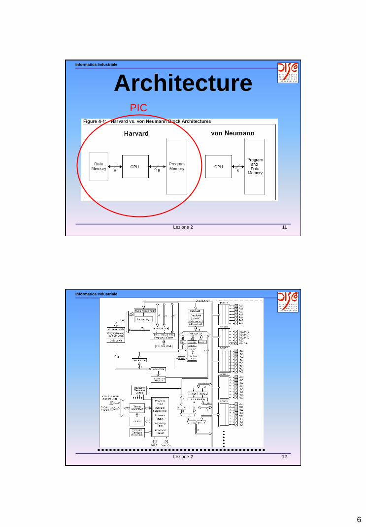
ArchitecturePIC
Informatica Industriale
Lezione 2 12
7
Informatica Industriale
Lezione 2 13
Informatica Industriale
Lezione 2 14
» Oscillator
» Reset
» Architecture
» CPU (Central Processing Unit) and System Bus
» ALU (Arithmetic Logical Unit)
» Hardware 8x8 Multiplier
» Memory Map
» Table Read / Table Write
» System Bus
» Interrupts
» Instruction Set
Device Structure: Core
8
Informatica Industriale
Lezione 2 15
» Oscillator
» Reset
» Architecture
» CPU (Central Processing Unit) & System Bus
» ALU (Arithmetic Logical Unit)
» Hardware 8x8 Multiplier
» Memory Map
» Table Read / Table Write
» System Bus
» Interrupts
» Instruction Set
Device Structure: Core
Informatica Industriale
Lezione 2 16
ALU (Arithmetic Logical Unit)
9
Informatica Industriale
Lezione 2 17
Status Register
• N =Negative bit
• OV=Overflow bit
• Z =Zero bit
• DC=Digit Carry (Half Carry)
• C =Carry
Informatica Industriale
Lezione 2 18
» Oscillator
» Reset
» Architecture
» CPU (Central Processing Unit) & System Bus
» ALU (Arithmetic Logical Unit)
» Hardware 8x8 Multiplier
» Memory Map
» Table Read / Table Write
» System Bus
» Interrupts
» Instruction Set
Device Structure: Core
10
Informatica Industriale
Lezione 2 19
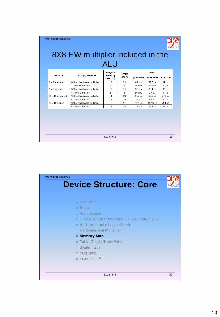
8X8 HW multiplier included in the
ALU
Informatica Industriale
Lezione 2 20
» Oscillator
» Reset
» Architecture
» CPU (Central Processing Unit) & System Bus
» ALU (Arithmetic Logical Unit)
» Hardware 8x8 Multiplier
» Memory Map
» Table Read / Table Write
» System Bus
» Interrupts
» Instruction Set
Device Structure: Core
11
Informatica Industriale
Lezione 2 21
Program & Data Memory
Informatica Industriale
Lezione 2 22
Program Memory Map
12
Informatica Industriale
Lezione 2 23
Data Memory Map
Informatica Industriale
Lezione 2 24
Access Bank
E’ una zona di memoria ad accesso veloce
formata dai primi 128byte del Bank0 (GPR) e
gli ultimi 128 del Bank15 (SFRs) ed è
utilizzata per:
• Intermediate computational values
• Local variables of subroutines
• Faster context saving/switching of variables
• Common variables
• Faster evaluation/control of SFRs (no banking)
Si accede quando a=0
13
Informatica Industriale
Lezione 2 25
» Oscillator
» Reset
» Architecture
» CPU (Central Processing Unit) & System Bus
» ALU (Arithmetic Logical Unit)
» Hardware 8x8 Multiplier
» Memory Map
» Table Read / Table Write
» System Bus
» Interrupts
» Instruction Set
Device Structure: Core
Informatica Industriale
Lezione 2 26
» Oscillator
» Reset
» Architecture
» CPU (Central Processing Unit) & System Bus
» ALU (Arithmetic Logical Unit)
» Hardware 8x8 Multiplier
» Memory Map
» Table Read / Table Write
» System Bus
» Interrupts
» Instruction Set
Device Structure: Core
14
Informatica Industriale
Lezione 2 27
InterruptsInterrupts can come from many sources. These sources currently include:
– External interrupt from the INT, INT1, and INT2 pins
– Change on RB7:RB4 pins
– TMR0,1,2,3Overflow
– USART Interrupts
• Receive buffer full
• Transmit buffer empty
– SSPInterrupt
– SSP I2C bus collision interrupt
– A/D conversion complete
– CCP interrupt
– LVD Interrupt
– Parallel Slave Port
– CAN interrupts
• Receive 1,2 buffer
• Receive invalid
• Transmit 1,2,3 buffer
• Bus wakeup
• Bus invalid error
Informatica Industriale
Lezione 2 28
InterruptsAs other peripheral modules are developed, they will have interrupt sources.
These sources will map into the 10 registers used in the control and status of interrupts. These registers are:
– INTCON
– INTCON1
– INTCON2
– INTCON3
– PIR1
– PIR2
– PIE1
– PIE2
– IPR1
– IPR2
The INTCON register contains the GIE/GIEH bit. This is the Global Interrupt Enable bit. When this bit is set, all interrupts are enabled. If needed for any single device, additional INTCON, PIR,PIE, and IPR registers will be defined.
15
Informatica Industriale
Lezione 2 29
Informatica Industriale
Lezione 2 30
Interrupt Registers:INTCON
16
Informatica Industriale
Lezione 2 31
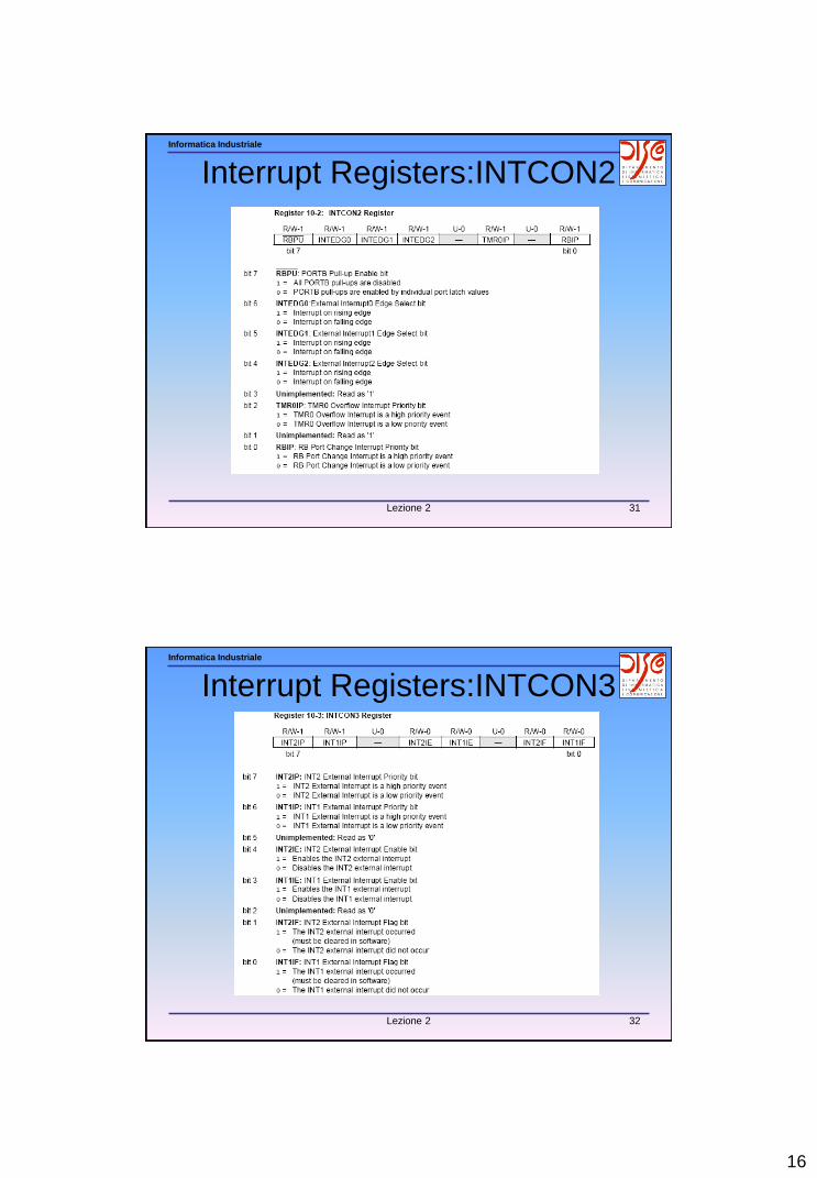
Interrupt Registers:INTCON2
Informatica Industriale
Lezione 2 32
Interrupt Registers:INTCON3
17
Informatica Industriale
Lezione 2 33
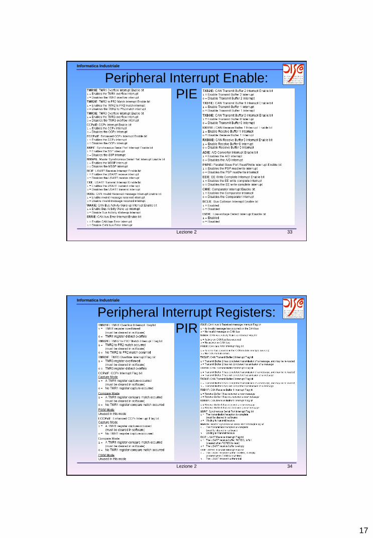
Peripheral Interrupt Enable:
PIE
Informatica Industriale
Lezione 2 34
Peripheral Interrupt Registers:
PIR
18
Informatica Industriale
Lezione 2 35
Interrupt Priority Registers:
IPR
Informatica Industriale
Lezione 2 36
Peripheral Interrupt Registers:
PIR
19
Informatica Industriale
Lezione 2 37
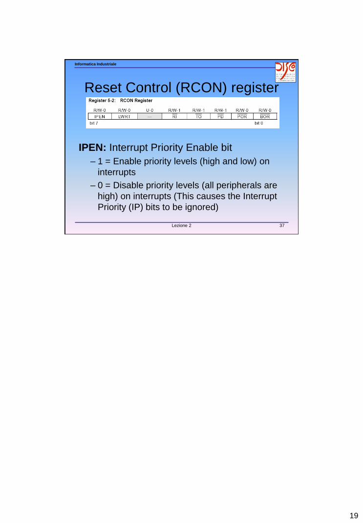
Reset Control (RCON) register
IPEN: Interrupt Priority Enable bit
– 1 = Enable priority levels (high and low) on
interrupts
– 0 = Disable priority levels (all peripherals are