INTERNATIONAL STANDARD ISO/IEC 19794-5:2005 TECHNICAL CORRIGENDUM 2 Published 2008-07-01
INTERNATIONAL ORGANIZATION FOR STANDARDIZATION • МЕЖДУНАРОДНАЯ ОРГАНИЗАЦИЯ ПО СТАНДАРТИЗАЦИИ • ORGANISATION INTERNATIONALE DE NORMALISATIONINTERNATIONAL ELECTROTECHNICAL COMMISSION • МЕЖДУНАРОДНАЯ ЭЛЕКТРОТЕХНИЧЕСКАЯ КОМИССИЯ • COMMISSION ÉLECTROTECHNIQUE INTERNATIONALE
Information technology — Biometric data interchange formats — Part 5: Face image data
TECHNICAL CORRIGENDUM 2
Technologies de l'information — Formats d'échange de données biométriques —
Partie 5: Données d'image de la face
RECTIFICATIF TECHNIQUE 2
Technical Corrigendum 2 to ISO/IEC 19794-5:2005 was prepared by Joint Technical Committee ISO/IEC JTC 1, Information technology, Subcommittee SC 37, Biometrics.
Page 23, 7.2.2
Replace 7.2.2 with the following:
7.2.2 Pose
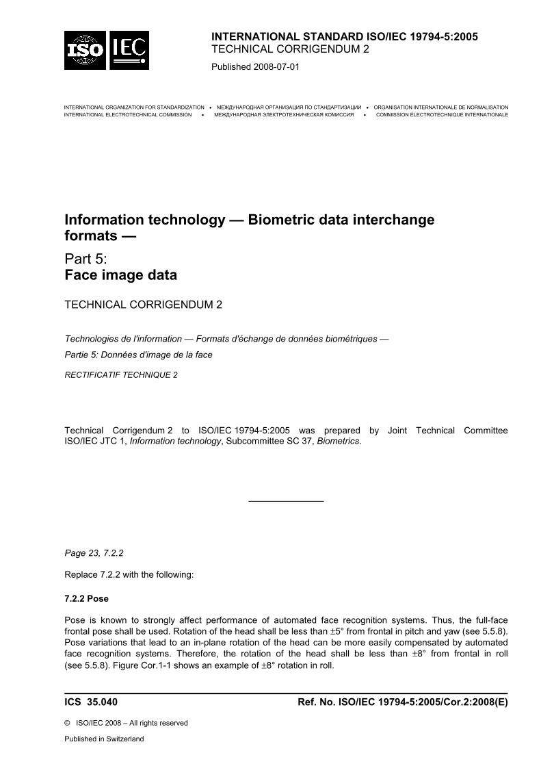
Pose is known to strongly affect performance of automated face recognition systems. Thus, the full-face frontal pose shall be used. Rotation of the head shall be less than ±5° from frontal in pitch and yaw (see 5.5.8). Pose variations that lead to an in-plane rotation of the head can be more easily compensated by automated face recognition systems. Therefore, the rotation of the head shall be less than ±8° from frontal in roll (see 5.5.8). Figure Cor.1-1 shows an example of ±8° rotation in roll.
Figure Cor.1-1 — Sample images with +8° (left) and −8° (right) rotation in roll
The best practice recommendation as outlined in A.2.2 is that the rotation of the head should be less than ±5° from frontal in roll.
This constraint refers to the pose of the subject associated with the face image format data for all applications that call for this format to be used.
Pages 27–29, 8.3.1 to 8.3.6
Replace 8.3.1 to 8.3.6 with the following:
8.3.1 Introduction
The minimum relative dimensions of the full image with respect to the face are specified in 8.3.2 to 8.3.6. The requirements of 8.3.2 to 8.3.6 can be met by images taken in both portrait and landscape mode. Figure 9 shows a portrait image and head outline to display dimensions A, B, BB, CC, and DD which are referenced in 8.3.2 to 8.3.6. In addition to the requirements of 8.3.2 to 8.3.6, the face from chin to crown as defined in 8.3.5 and with the full width as defined in 8.3.4 shall be visible in the image.
Additional constraints on image and head dimensions for sizes appropriate specifically to travel documents are discussed in A.3.2.
Note that for digital images the normative requirements related to the minimum inter-eye distance as defined in 8.4.1 impose further requirements on the minimum head size. A.3.1.1 gives more information on the connection between photo resolution and the photographic requirements of 8.3.2 to 8.3.6.
NOTE This figure is a derivative of AAMVA document DL/ID-2000.
Figure 9 — Geometric characteristics of the full frontal face image
8.3.2 Horizontally centred face
The approximate horizontal midpoints of the mouth and of the bridge of the nose define the imaginary line AA (usually the symmetry axis of the face). Furthermore, the imaginary line BB is defined as the line through the centre of the left eye and the centre of the right eye. The intersection of AA and BB defines the point M as the centre of the face. The x-coordinate Mx of M shall be between 45 % and 55 % of the image width.
8.3.3 Vertical position of the face
The y-coordinate My of M shall be between 30 % and 50 % of the image height. A single exception is allowed for children under the age of 11 years, in which case the higher limit shall be modified to 60 % (i.e. the centre point of the head is allowed to be lower in the image for children under the age of 11). Note that the origin O of the coordinate system is in the upper left corner of the image.
8.3.4 Width of head
The width of a head is defined as the distance between the two imaginary lines parallel to the line AA; each imaginary line is drawn between the upper and lower lobes of each ear and shall be positioned where the external ear connects to the head. The head width is shown as length CC in Figure 9.
To ensure that the entire face is visible in the image, the head width (CC) shall be between 50 % and 75 % of the image width (A).
8.3.5 Length of head
The length of a head is defined as the distance between the base of the chin and the crown measured on the imaginary line AA. This is shown as length DD in Figure 9. The crown is defined as the top of the head ignoring any hair.
In order to assure that the entire face is visible in the image, the minimum image height shall be specified by requiring that the crown-to-chin portion (DD) of the full frontal image pose shall be between 60 % and 90 % of the vertical length of the image (B). A single exception is allowed for children under the age of 11 years, in which case the lower limit shall be modified to 50 %.
8.3.6 Summary of photographic requirements
Table 15 summarizes the photographic requirements for full frontal images specified in 8.3.1 to 8.3.5.
Table 15 — Summary of photographic requirements for full frontal images
Section Definition Requirements 8.3.1 General requirement Head entirely visible in
the image 8.3.2 Horizontal position of face 0,45 A u xM u 0,55 A 8.3.3 Vertical position of face 0,3 B u yM u 0,5 B
8.3.3 Vertical position of face (children under the age of 11)
0,3 B u yM u 0,6 B
8.3.4 Width of head 0,5 A u CC u 0,75 A 8.3.5 Length of head 0,6 B u DD u 0,9 B 8.3.5 Length of head
(children under the age of 11) 0,5 B u DD u 0,9 B
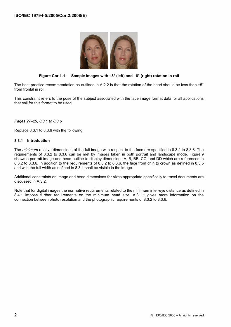
Figure Cor.1-2 shows a typical example of a passport image. The outer rectangle visualizes the maximum dimensions of the head based on the requirements in 8.3.4 and 8.3.5. Furthermore, the inner rectangle shows the minimum width and height dimensions of the head based on the image dimensions.
Figure Cor.1-2 — A sample image with the respective minimal and maximal head dimensions based on the image width and height
Add the following subclause before A.2.2 and renumber subsequent subclauses of A.2:
A.2.2 Pose
The full-face frontal pose should be used. Rotation of the head should be less than ±5° from frontal in every direction – roll, pitch and yaw (see 5.5.8).
Page 34; A.3.1.1
In list item 2), replace “13 mm inches” with “13 mm”.
Add the following at the end of A.3.1.1:
On the other hand, if photographs are scanned at 120 pixels per centimetre (300 ppi) the requirement of 90 pixels minimum inter-eye distance corresponds to an inter-eye distance of approximately 8 mm. In analogy, the best practice requirement of 120 pixels minimum inter-eye distance corresponds to an inter-eye distance of approximately 10 mm for photographs scanned at 120 pixels per centimetre (300 ppi).
Page 35
Replace A.3.2.3 with the following:
A 3.2.3 Summary of best practice photographic recommendations
For convenience, Table 17 summarizes the geometric and pose constraints in A.2.2 and A.3.2.1 to A.3.2.2.
Table 17 — Summary best practices for full frontal images on travel documents
Page 46
Add the following new clause after A.4.6:
A.5 Experimental study on the enrolment of full frontal images for travel documents
This clause describes a study, the results from which provide justification for the tolerances regarding inter-eye distance, relative horizontal position of the face, relative vertical position of the face, head to image width ratio and head to image height ratio.
Section Definition Recommendation
A.2.2 Pose ±5° from frontal in roll, pitch and yaw
A.3.2.1 Width-to-height ratio of image 1,25 u B/A u 1,34 A.3.2.2 Width of head 1,4 CC u A u 2 CC A.3.2.2 Length of head 0,7 B u DD u 0,8 B A.3.2.2 Length of head
The parameters and tolerances used in this study were either
1. the strict tolerances as demanded by this part of ISO/IEC 19794 and ICAO recommendations,
2. the relaxed tolerances as suggested by ICAO for the real-world application of passport image enrolment.
The data used for this study was derived from a large scale sampling of e-passport photographs. The data were contributed by the governments of four high volume e-passport issuing States. All images used in this study were already accepted for the issuance of an e-passport in the respective countries.
The focus of the analysis performed was largely on whether typical passport photos meet the key specifications set out in this part of ISO/IEC 19794; in particular those with respect to
1. pose,
2. pixel resolution between the eye centres,
3. relative horizontal position of the face,
4. relative vertical position of the face,
5. head to image width ratio, and
6. head to image height ratio.
Table 19 — Real-world image datasets used for the analysis
Dataset country No. of images Pixel size (width x height) Format 0 1000 413 x 531 JPEG A 1988 384 x 480 JPEG B 1911 449 x 599 JPEG C 2229 416 x 536 JPEG
The data derived from these passport images are subsequently compared with each other and with the tolerances specified by this part of ISO/IEC 19794.
A.5.2 Experimental results
A.5.2.1 Inter-eye distance
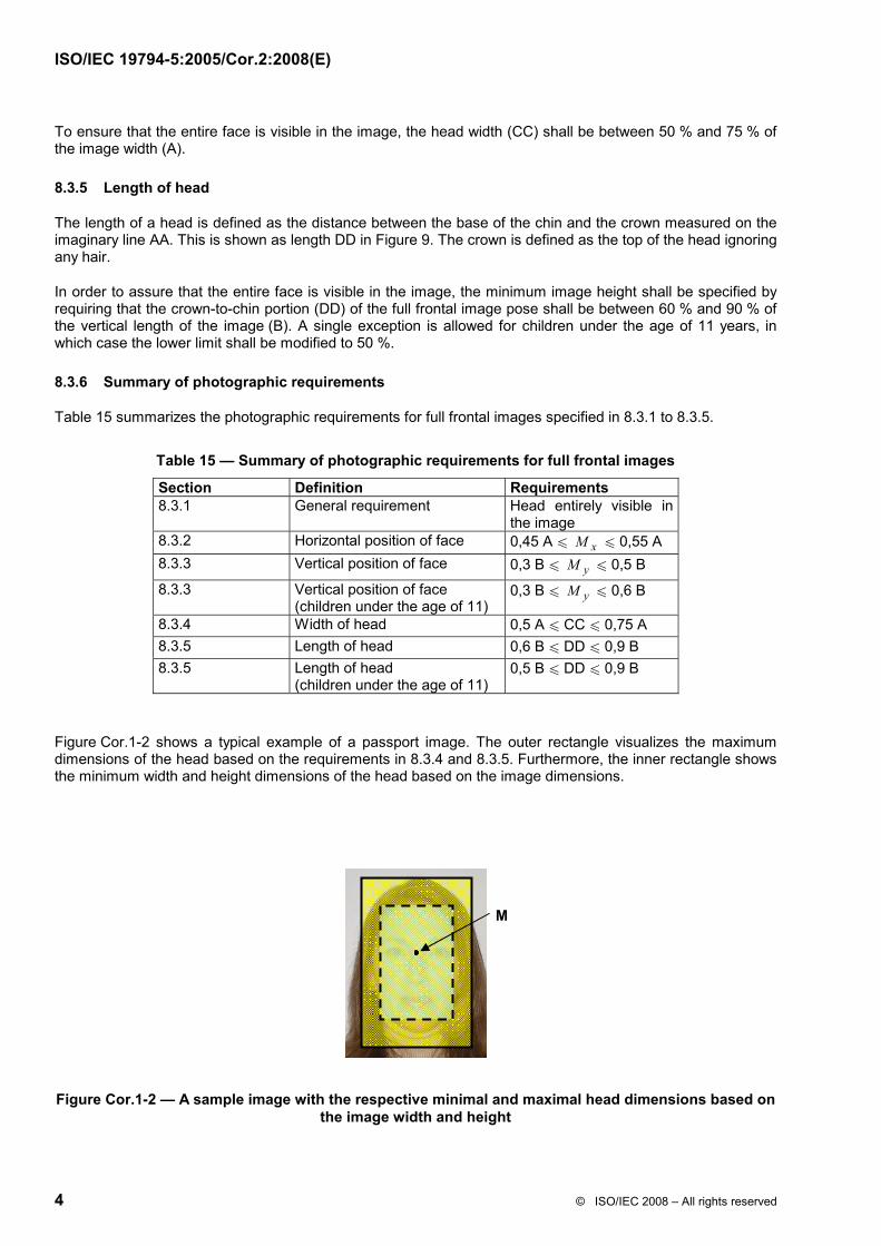
This part of ISO/IEC 19794 specifies a minimum of 90 pixels between eye centres for full frontal images (see 8.4.1). Figure 21 shows the distribution of the inter-eye centres for the four sample data sets.
The requirement of 90 pixels between the eyes was met in almost all of the cases. The average distance between the eyes was found to be at 123,4 pixels.
A.5.2.2 Relative horizontal position of the face
This part of ISO/IEC 19794 specifies that the x-coordinate M x of the centre of the face M shall be between 45 % and 55 % of the image width (see 8.3.2). Figure 22 shows the distribution of the horizontal position of the face ( AM x ) for the four sample data sets.
The average horizontal head position of the 7 128 images is at approximately 49 % of the image width. The specifications of this part of ISO/IEC 19794 have been met by 95,4 % of all passport photos of this study.
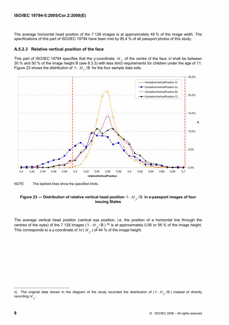
A.5.2.3 Relative vertical position of the face
This part of ISO/IEC 19794 specifies that the y-coordinate yM of the centre of the face M shall be between 30 % and 50 % of the image height B (see 8.3.3) with less strict requirements for children under the age of 11. Figure 23 shows the distribution of 1 /ByM− for the four sample data sets.
Figure 23 — Distribution of relative vertical head position 1 /BM y− in e-passport images of four issuing States
The average vertical head position (vertical eye position, i.e. the position of a horizontal line through the centres of the eyes) of the 7 128 images (1 /BM y− ) 4) is at approximately 0,56 or 56 % of the image height. This corresponds to a y-coordinate of M (M y ) of 44 % of the image height.
4) The original data shown in the diagram of the study recorded the distribution of (1 /BM y− ) instead of directly recordingM y .
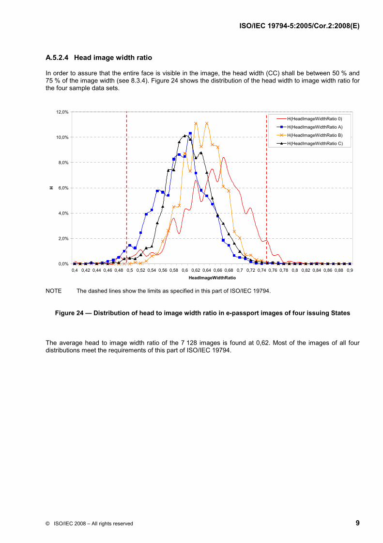
In order to assure that the entire face is visible in the image, the head width (CC) shall be between 50 % and 75 % of the image width (see 8.3.4). Figure 24 shows the distribution of the head width to image width ratio for the four sample data sets.
NOTE The dashed lines show the limits as specified in this part of ISO/IEC 19794.
Figure 24 — Distribution of head to image width ratio in e-passport images of four issuing States
The average head to image width ratio of the 7 128 images is found at 0,62. Most of the images of all four distributions meet the requirements of this part of ISO/IEC 19794.
In order to assure that the entire face is visible in the image, this part of ISO/IEC 19794 specifies that the crown to chin portion (DD) of the full frontal image shall be between 60 % and 90 % of the vertical length of the image (B) (see 8.3.5). Figure 25 shows the distribution of the head height to image height ratio for the four sample data sets.
0,0%
2,0%
4,0%
6,0%
8,0%
10,0%
12,0%
14,0%
0,5 0,55 0,6 0,65 0,7 0,75 0,8 0,85 0,9 0,95 1
HeadImageHeightRatio
H
H(HeadImageHeightRatio 0)
H(HeadImageHeightRatio A)
H(HeadImageHeightRatio B)
H(HeadImageHeightRatio C)
Figure 25 — Distribution of head to image height ratio in e-passport images of four issuing States
The average head to image width ratio of the 7 128 images is found at 0,73. A total of 98,2 % of the data fits within the tolerances specified by this part of ISO/IEC 19794.
A.5.3 Error discussion
The analysis of this study is solely based on the measurements done by automated image quality assurance software (QA-SW). No comparison with the so-called ground truth, i.e. the true (manually measured) values for the parameters under consideration, was performed for all the images. However, this was done at an earlier stage for one country's passport images, where the quality assessment software being used was found to be reasonably accurate, and able to produce reliable statistics for larger datasets such as those reported above.
Additional studies comparing the quality assessment software used for this study with other quality assessment software packages on a large number of passport images showed approximately the following deviations:
That is, except for the eye distance, which is reported slightly larger than might be expected to be true, the other parameters may be expected to be correct within an error margin of 1 %.
The study presented in this annex concentrates on geometrical parameters of the face in the photograph which are important for biometric matching applications. The findings of the study are based on the statistical evaluation of automated image analysis by quality assessment software. Even if individual decisions of the software may have been incorrect, the conclusions based on the aggregation of approximately 7 200 images are certainly valid.
In summary, the analysis given above shows that with current technology the thresholds set forth in this part of ISO/IEC 19794 can be achieved in real world applications. Table 20 and Figure 26 illustrate a summary of these findings. Since the data used for this study were collected from four major e-passport issuing countries across the world, the results can be regarded as representative within the scope of this analysis.
Table 20 — Summary of the compliance of the sample with the requirements specified in this part of ISO/IEC 19794
Criteria Minimum Maximum Images compliant Eyes distance, min. [pixel] 90,00 — 99,9 % Relative horizontal position 0,45 0,55 95,4 % Relative vertical position 0,50 0,70 94,0 % Head to image width ratio 0,50 0,75 98,4 % Head to image height ratio 0,60 0,90 98,2 %
Figure 26 — Percentage of compliant passport photos in the test set of 7 128 images of four issuing States using the tolerances given in 8.3.1 to 8.3.6
A.6 Experimental study on the effects of inter-eye distance and the effect of head pose (roll) on biometric matching performance
A.6.1 Inter-eye distance
The distance between the eyes (i.e. the resolution of the photo) is considered to be one of the most important criteria for successfully applying facial recognition. In order to quantify the effect of “pixels between the eyes” on facial recognition performance, images of varying resolution were investigated using a state-of-the-art facial matching algorithm. Figure 27 shows an increasing verification rate with increasing eye distance. These results also hold for investigations of the identification performance (rank statistics).
Impact of Inter-eye Distance on Performance
95,00
95,50
96,00
96,50
97,00
97,50
98,00
98,50
99,00
0 20 40 60 80 100 120 140 160
Inter-eye Distance [Pixel]
Norm
aliz
ed V
erifi
catio
n Ra
te [%
]
Figure 27 — Normalized verification rate plotted against inter-eye distance at FAR = 0,1 %
A.6.2 Pose
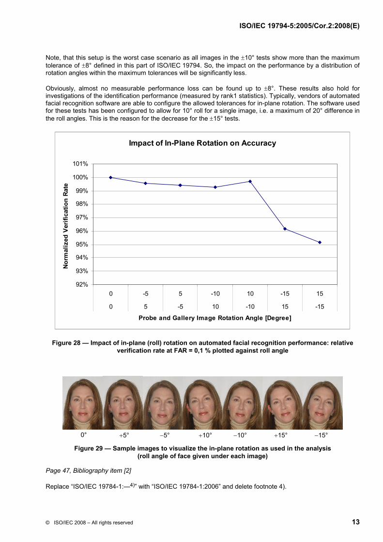
Automated face recognition systems allow for effective compensation of the roll angle of a facial image. Figure 28 shows the facial recognition performance impact due to in-plane (roll axis) rotation of the images.
For the test, 994 gallery images and 736 probe images from the “Feret Color” dataset have been used. In a first step, all images (probe and gallery) have been rotated, so that they show zero roll angle. Then tests have been carried out, where all probes have been rotated by +5° and all gallery images by −5°, then vice versa. This has been repeated for 10°, −10°,15° and −15°. So, the delta in roll angle of probe and gallery is 0°, 10°, 20° and 30°. Figure 29 shows some sample data demonstrating the effect of the rotation.
The verification rate at 0,1 % FAR and 0° has been used to determine the loss due to in-plane rotation, i.e. all other verification rates have been normalized to the verification rate at 0,1 % FAR of the 0° evaluation.
Note, that this setup is the worst case scenario as all images in the ±10° tests show more than the maximum tolerance of ±8° defined in this part of ISO/IEC 19794. So, the impact on the performance by a distribution of rotation angles within the maximum tolerances will be significantly less.
Obviously, almost no measurable performance loss can be found up to ±8°. These results also hold for investigations of the identification performance (measured by rank1 statistics). Typically, vendors of automated facial recognition software are able to configure the allowed tolerances for in-plane rotation. The software used for these tests has been configured to allow for 10° roll for a single image, i.e. a maximum of 20° difference in the roll angles. This is the reason for the decrease for the ±15° tests.
Impact of In-Plane Rotation on Accuracy
92%
93%
94%
95%
96%
97%
98%
99%
100%
101%
0 -5 5 -10 10 -15 15
0 5 -5 10 -10 15 -15
Probe and Gallery Image Rotation Angle [Degree]
Nor
mal
ized
Ver
ifica
tion
Rate
Figure 28 — Impact of in-plane (roll) rotation on automated facial recognition performance: relative verification rate at FAR = 0,1 % plotted against roll angle
Figure 29 — Sample images to visualize the in-plane rotation as used in the analysis (roll angle of face given under each image)
Page 47, Bibliography item [2]
Replace “ISO/IEC 19784-1:—4)” with “ISO/IEC 19784-1:2006” and delete footnote 4).


![Biometric Standards documents/Standards... · Biometric Profiles Biometric [Application] Profile – a conforming subset or combination of base standards used to effect specific biometric](https://static.documents.pub/doc/80x56/5f711372ce578d4ee02aea91/biometric-standards-documentsstandards-biometric-profiles-biometric-application.jpg)


