60
Huffman Codes Prof. Ja-Ling Wu Department of Computer Science and Information Engineering National Taiwan University

Huffman Codes
Prof. Ja-Ling Wu
Department of Computer Science
and Information Engineering
National Taiwan University
2
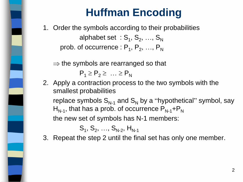
Huffman Encoding
1. Order the symbols according to their probabilities
alphabet set : S1, S2, …, SN
prob. of occurrence : P1, P2, …, PN
the symbols are rearranged so that
P1 P2 … PN
2. Apply a contraction process to the two symbols with the
smallest probabilities
replace symbols SN-1 and SN by a “hypothetical” symbol, say
HN-1, that has a prob. of occurrence PN-1+PN
the new set of symbols has N-1 members:
S1, S2, …, SN-2, HN-1
3. Repeat the step 2 until the final set has only one member.

3
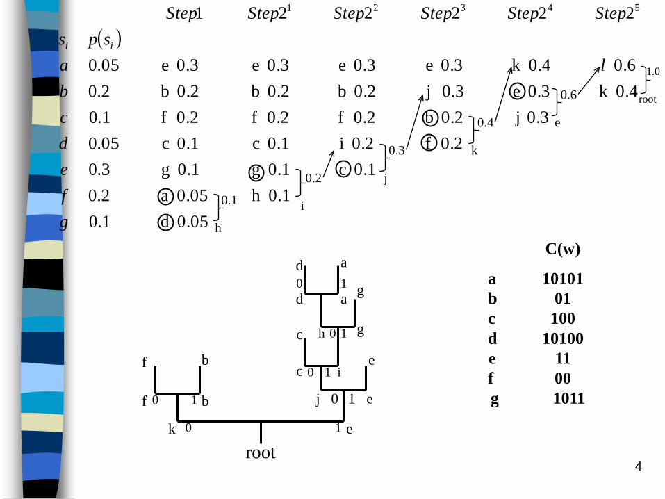
The recursive procedure in step 2 can be viewed as
the construction of a binary tree, since at each step we
are merging two symbols.
At the end of the recursion, all the symbols S1, S2, …,
SN will be leaf nodes of the tree.
The codeword for each symbol Si is obtained by
traversing the binary tree from its root to the leaf
node corresponding to Si
4root
k e
f
f
b
b
1 e
ec
c
g
g
a
a
d
d
h
1 i
j 0
0
0
0
0
0
1
1
1
1
C(w)
a 10101
b 01
c 100
d 10100
e 11
f 00
g 1011
0.05 d 1.0
0.1h 0.05 a 2.0
0.1 c0.1 g 0.1 g 3.0
0.2 f0.2 i0.1 c 0.1 c05.0
0.3 j0.2 b0.2 f0.2 f 0.2 f 1.0
0.4k 0.3 e0.3 j0.2 b0.2 b 0.2 b 2.0
0.6 0.4k 0.3 e0.3 e0.3 e 0.3 e05.0
222221 54321
g
f
e
d
c
b
la
sps
StepStepStepStepStepStep
ii
0.1
h
0.2
i
0.3
j
0.4
k
0.6
e
1.0
root
5
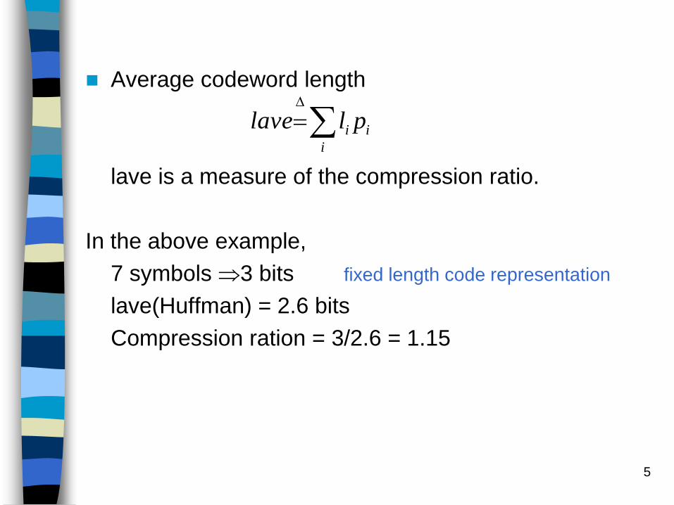
Average codeword length
lave is a measure of the compression ratio.
In the above example,
7 symbols 3 bits fixed length code representation
lave(Huffman) = 2.6 bits
Compression ration = 3/2.6 = 1.15
i
ii pllave

6
Properties of Huffman codes
Fixed-length symbols variable-length codewords :
error propagation
H(s) lave < H(s)+1
H(s) lave < P+0.086
where P is the prob. of the most frequently occurring
symbol. The equality is achieved when all symbol
probs. are inverse powers of two.
The Huffman code-tree can be constructed both by
bottom-up method in the above example
top-down method

7
The code construction process has a complexity of O(Nlog2N). With presorting of the input symbol probs, code construction method with complexity O(N) has been presented in IEEE trans. ASSP-38, pp. 1619-1626, Sept. 1990.
Huffman codes satisfy the prefix-condition : uniquely decodable: no codeword is a prefix of another codeword.
If li satisfy the Kraft constraint then the corresponding codewords can be constructed as the first li bits in the fractional representation of ai
The complement of a binary Huffman code is also a valid Huffman code.
12 il
}1,0{;,,2,1 ,21
1
i
i
j
l
ii cNica j

8
Huffman Decoding
Bit-Serial Decoding : fixed input bit rate — variable output symbol rate
(Assume the binary coding tree is available to the decoder)In practice, Huffman coding tree can be reconstructed from the symbol-to-codeword mapping table that is known to both the encoder and the decoder
Step 1:
Read the input compressed stream bit-by-bit and traverse the tree until a leaf node is reached.
Step 2:
As each bit in the input stream is used, it is discarded. When the leaf node is reached, the Huffman decoder outputs the symbol at the leaf node. This completes the decoding for this symbol.
Step 3:
Repeat steps 1 and 2 until all the input is consumed.
Since the codeword is variable in length, the decoding bit rate is not the same for all symbols.

9
Lookup-table-Based Decoding : constant decoding
rate for all symbols — variable input rate
The look-up table is constructed at the decoder from the symbol-
to-codeword mapping table. If the longest codeword in this table
is L bits, then a 2L entry lookup table is needed. : space constraints
image/video longest L = 16 to 20.
Look up table construction:
– Let Ci be the codeword that corresponds to symbol Si.Assume
Ci has li bits. We form an L-bit address in which the first li bits
are Ci and the remaining L- li bits take on all possible
combinations of “0” and “1”. Thus, for the symbol si, there will
be 2L- li addresses.
– At each entry we form the two-tuple (si, li).

10
Decoding Processes:
1. From the compressed input bit stream, we read in L bits into
a buffer.
2. We use the L-bit word in the buffer as an address into the
lookup table and obtain the corresponding symbol, say sk.
Let the codeword length be lk. We have now decode one
symbol.
3. We discard the first lk bits from the buffer and we append to
the buffer, the next lk bits from the input, so that the buffer
has again L bits.
4. Repeat steps 2 and 3 until all of the symbols have been
decoded.

11
Memory Efficient and High-Speed
Search Huffman Coding, by R. Hashemian IEEE
trans. Communications, Oct. 1995, pp. 2576-2581
Due to variable-length coding, the Huffman tree gets
progressively sparse as it grows from the root
– Waste of memory space
– A lengthy search procedure for locating a symbol
Ex: if K-bit is the longest Huffman code assigned to a set
of symbols, the memory size for the symbols may
easily reach 2K words in size.
It is desirable to reduce the memory size from typical
value of 2K, to a size proportional to the number of the
actual symbols.
– Reduce memory size
– Quicker access
12
Ordering and clustering based Huffman Coding
groups the codewords (tree nodes) within specified codeword lengths
Characteristics of the proposed coding scheme:
1. The search time for more frequent symbols (shorter codes) is
substantially reduced compare to less frequent symbols,
resulting in an overall faster response.
2. For long codewords the search for the symbol is also speed
up. This is achieved through a specific partitioning technique
that groups the code bits in a codeword, and the search for a
symbol is conducted by jumping over the groups of bits
rather than going through the bit individually.
3. The growth of the Huffman tree is directed toward one side of
the tree.
– Single side growing Huffman tree (SGH-tree)

13
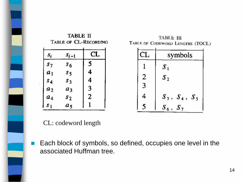
Ex: H=(S, P) S={S1, S2,…, Sn}
P={P1, P2,…, Pn}
No. of occurrence
For a given source listing H, the table of codeword length uniquely groups the symbols into blocks, where each block is specified by its codeword length (CL).
TABLE IReduction Process In The Source List
s1 48 s1 48 s1 48 s1 48 s1 48 a5 52
s2 31 s2 31 s2 31 s2 31 s2 31 s1 48
s3 7 s3 7 a2 8 a3 13 a4 21
s4 6 s4 6 s3 7 a2 8
s5 5 s5 5 s4 6
s6 2 a1 3
s7 1
Merge
Insert (in descending order)
14
Each block of symbols, so defined, occupies one level in the
associated Huffman tree.
CL: codeword length

15
Algorithm 1: Creating a Table of Codeword Lengths
1. The symbols are listed with the probabilities in decending
order (the ordering of the symbols with equal probabilities is
assumed indifferent).
Next, the pair of symbols at the bottom of the ordered list are
merged and as a result a new symbol a1 is created. The
symbol a1, with probability equal to the sum of the
probabilities of the pair, is then inserted at the proper location
in the ordered list.
To record this operation a codeword length recording (CLR)
table is created which consists of three columns:
: Columns 1 and 2 hold the last pair of symbols before being
merged, and column 3, initially empty, is identified as the
codeword length (CL) column (Table II).
16
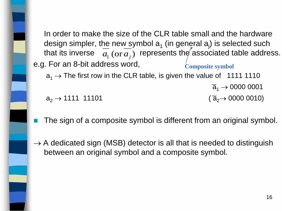
In order to make the size of the CLR table small and the hardware
design simpler, the new symbol a1 (in general aj) is selected such
that its inverse represents the associated table address.
e.g. For an 8-bit address word,
a1 The first row in the CLR table, is given the value of 1111 1110
a1 0000 0001
a2 1111 11101 ( a2 0000 0010)
The sign of a composite symbol is different from an original symbol.
A dedicated sign (MSB) detector is all that is needed to distinguish
between an original symbol and a composite symbol.
)(or 1 jaa
Composite symbol
17
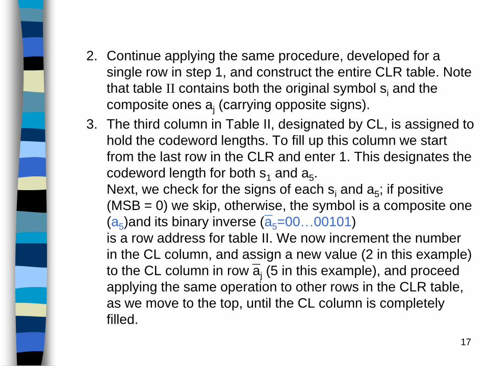
2. Continue applying the same procedure, developed for a
single row in step 1, and construct the entire CLR table. Note
that table II contains both the original symbol si and the
composite ones aj (carrying opposite signs).
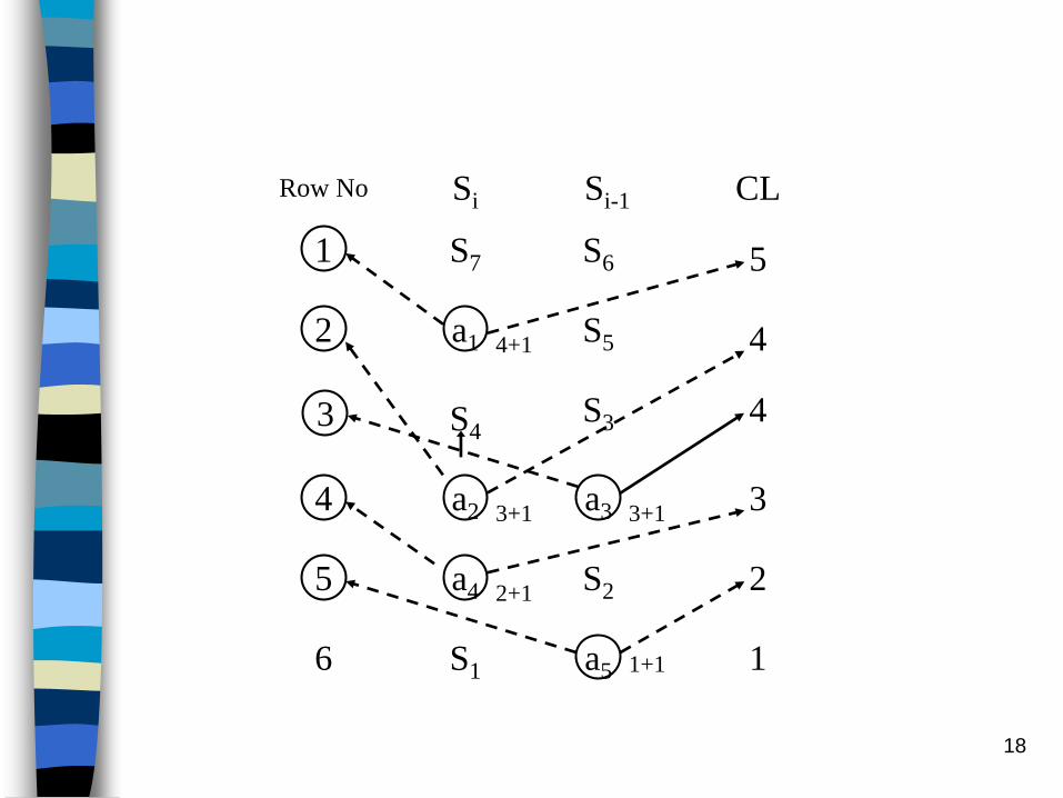
3. The third column in Table II, designated by CL, is assigned to
hold the codeword lengths. To fill up this column we start
from the last row in the CLR and enter 1. This designates the
codeword length for both s1 and a5.
Next, we check for the signs of each si and a5; if positive
(MSB = 0) we skip, otherwise, the symbol is a composite one
(a5)and its binary inverse (a5=00…00101)
is a row address for table II. We now increment the number
in the CL column, and assign a new value (2 in this example)
to the CL column in row aj (5 in this example), and proceed
applying the same operation to other rows in the CLR table,
as we move to the top, until the CL column is completely
filled.
18
1
2
4
5
6
S7 S6
S5
S3S4
a2
a4
S1
a1
a3
a5
S2
3
2
1
4
4
5
CLSi Si-1Row No
1+1
3+13+1
2+1
4+1
3
19
role:
(i) Si, Si-1 中有一為 composite, 則以 composite 為 CL 增加及 new address 之基礎
(ii)若Si, Si-1皆為 original, skip this row and CL 不變
4. Table II indicates that each original symbol in the table has its codeword length (CL) specified.Ordering the symbols according the their CL values gives Table III.
Associated with the so-obtained TOCL one can actually generate a number of Huffman tables (or Huffman trees), each of which being different in codewords but identical in the codeword lengths.

20
Single-Side growing Huffman table (SGHT)
— TableⅣ
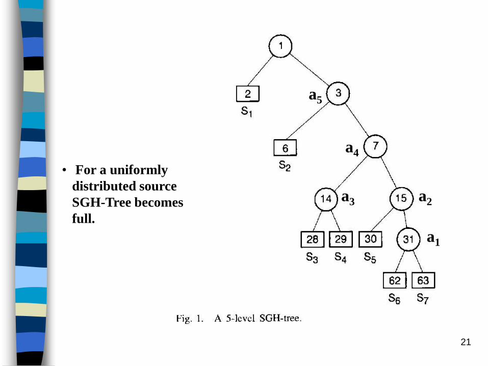
Single-Side growing Huffman tree (SGH-Tree)
— Fig. 1
are adopted.
21
a5
a4
a3 a2
a1
• For a uniformly
distributed source
SGH-Tree becomes
full.
22
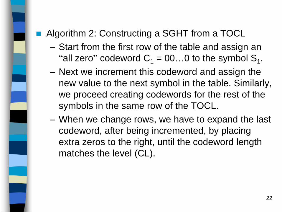
Algorithm 2: Constructing a SGHT from a TOCL
– Start from the first row of the table and assign an
“all zero” codeword C1 = 00…0 to the symbol S1.
– Next we increment this codeword and assign the
new value to the next symbol in the table. Similarly,
we proceed creating codewords for the rest of the
symbols in the same row of the TOCL.
– When we change rows, we have to expand the last
codeword, after being incremented, by placing
extra zeros to the right, until the codeword length
matches the level (CL).
23
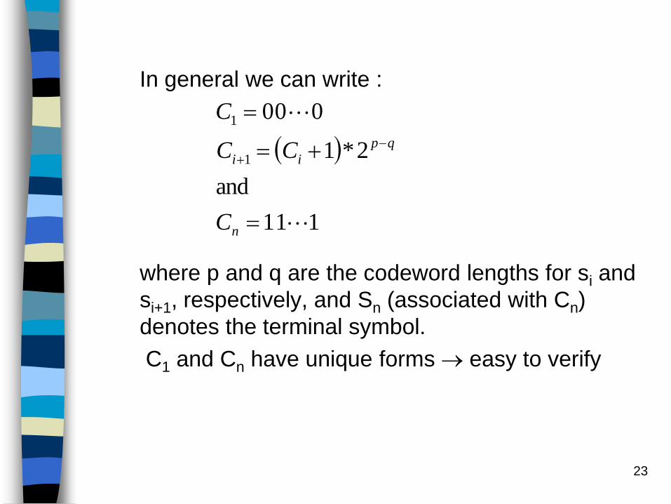
In general we can write :
where p and q are the codeword lengths for si and
si+1, respectively, and Sn (associated with Cn)
denotes the terminal symbol.
C1 and Cn have unique forms easy to verify
111
and
2*1
000
1
1
n
qp
ii
C
CC
C
24
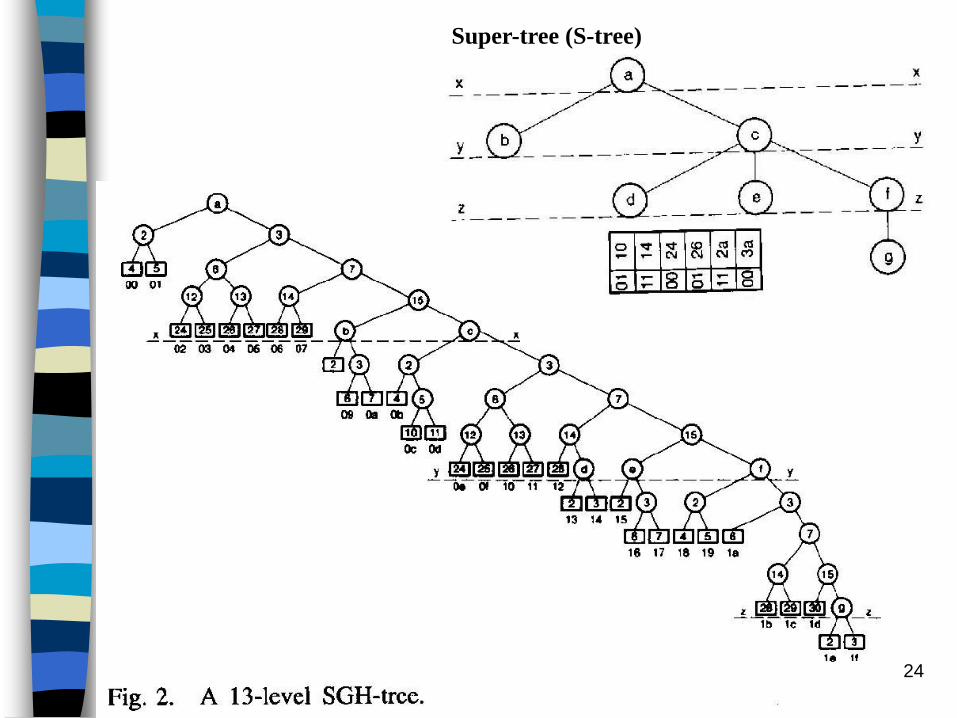
Super-tree (S-tree)

25
xx
yy
zz
26

27
0 1 2 3 4 5 6 7 8 9 a b c d e f
0 00 01 02 03 04 05 06 07
1 08 09 0a 0b 0c 0d 0e 0f 10 11
2 12 13 14 15 16 17 18 19 1a
3 1b 1c 1d 1e 1f
TABLE VIIMemory (RAM) Space Associated with Table VI and Figs. 3 and 4

28
Storage Allocation
For non-uniform source, SGH-Tree becomes sparse.
How to
i) optimize the storage space
ii) provide quick access to the symbol (data)
key Idea:
Break down the SGH-Tree into smaller clusters
(subtrees) such that the memory efficiency
increases.
The memory efficiency B for a K-level binary Huffman
tree%100
2
nodes leaf effective of No.
KKB

29
Ex:1
2 3
6 3
14 15
28 29 30 31
62 63
S1
S2
S3S4 S5
S6 S7
a1
a2a3
a4
a5
2/21 : 100%
3/22 : 75%
4/23 : 50%
6/24 : 37%
7/25 : 22%
30
Remarks:
1. The efficiency changes only when we switch to a new level
(or equivalently to a new CL), and it decreases as we
proceed to the higher levels.
2. Memory efficiency can be interpreted as a measure of the
performance of the system in terms of memory space
requirement; and it is directly related to the sparsity of the
Huffman tree.
3. Higher memory efficiency for the top levels (with smaller CL)
is a clear indication that partitioning the tree into smaller and
less sparse clusters will reduce the memory size. In addition,
clustering also helps to reduce the search time for a symbol.
Definition:
A cluster (subtree) Ti with minimum memory efficiency (MME) Bi,
if there is no level in Ti with memory efficiency less than Bi.
31
SGH-Tree Clustering
Given a SGH-tree, as shown in Fig. 2, depending on the MME (or CL) assigned, the tree is partitioned by a cut line, x-x, at the Lth level (L=4 for the choice of MME=50%, in this example).
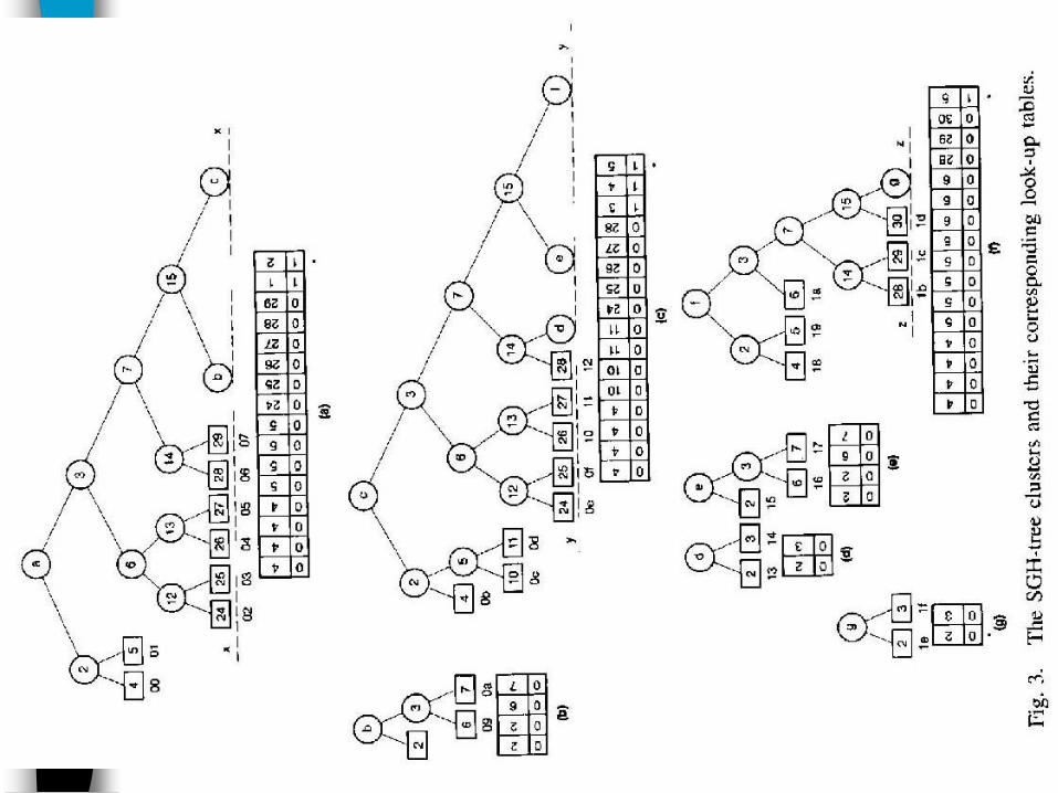
The first cluster (subtree), as shown in Fig.3(a), is formed by removing the remainder of the tree beyond the cut-line x-x.
The cluster length is defined to be the maximum path length from the root to a node within the cluster the cluster length for the first cluster is 4.
Associated with each cluster a look up table (LUT) is assigned, as shown at the bottom of Fig.3(a), to provide the addressing information for the corresponding terminal node (symbol) within the cluster, or beyond.

32
To identify other clusters, in the tree, we draw more cut lines y-y,
and z-z, each L levels apart.
More clusters are generated, each of which starting from a single
node (root of the cluster) and expanded until it is terminated
either by terminal nodes, or nodes being intercepted by the next
cute line.
Next, we construct a super-tree (s-tree) corresponding to a
SGH-Tree. In a s-tree each cluster is represented by a node,
and the links connecting these nodes, representing the branching
nodes in the SGH-tree, shared between two clusters.
The super-table (ST) associated with the s-tree is shown at the
bottom of the tree.
Note that the s-tree has 7 nodes, one for each cluster, while its
ST has 6 entries. This is because the root cluster a is left out and
the table starts from cluster b.
33
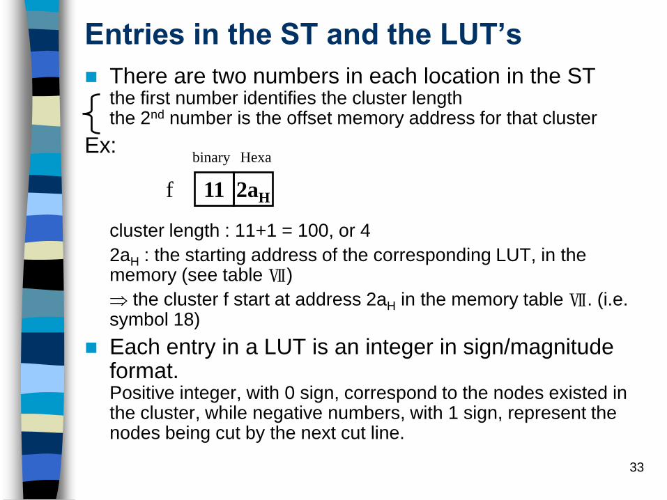
Entries in the ST and the LUT’s
There are two numbers in each location in the STthe first number identifies the cluster lengththe 2nd number is the offset memory address for that cluster
Ex:
cluster length : 11+1 = 100, or 4
2aH : the starting address of the corresponding LUT, in the memory (see table Ⅶ)
the cluster f start at address 2aH in the memory table Ⅶ. (i.e. symbol 18)
Each entry in a LUT is an integer in sign/magnitude format.Positive integer, with 0 sign, correspond to the nodes existed in the cluster, while negative numbers, with 1 sign, represent the nodes being cut by the next cut line.
11 2aHf
binary Hexa

34
The magnitude of a negative integer specifies a location in the ST,
for further search.For example, consider the cluster-C
4 4 4 4 10 10 11 11 24 25 26 27 28 3 4 5
0 0 0 0 0 0 0 0 0 0 0 0 0 1 1 1
1 2 3 4 5 6 7 8 9 10 11 12 13 14 15 16
Sig
n/m
agn
itude f28 ed27262524
0e 0f 10 11 12yy
14 15
76
12 13
4
6
C
5
2
10 110c 0d
0b
35
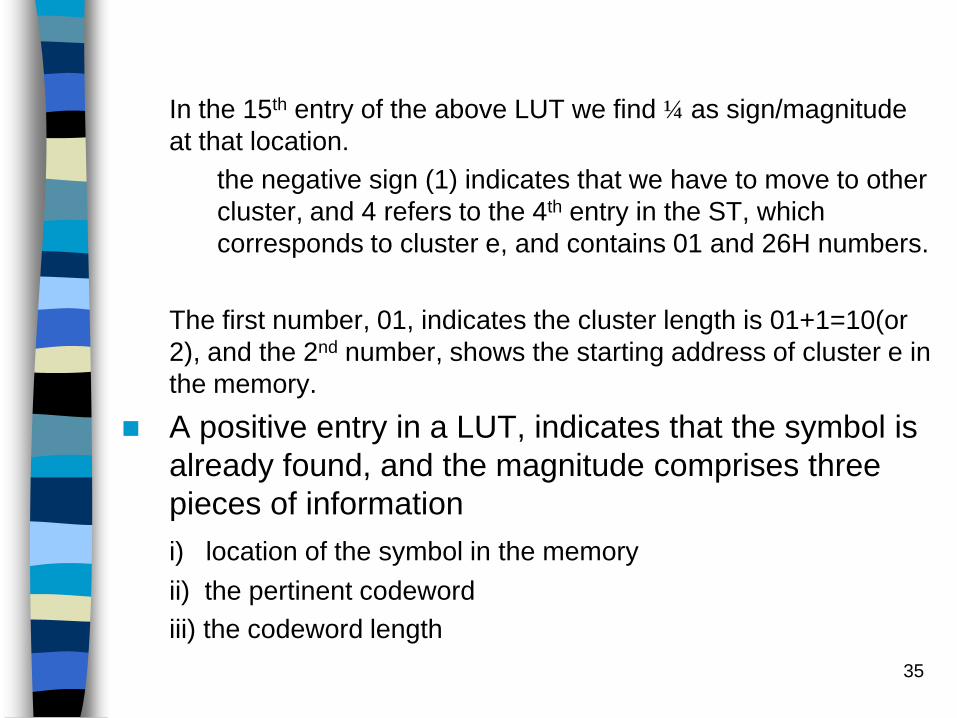
In the 15th entry of the above LUT we find ¼ as sign/magnitude
at that location.
the negative sign (1) indicates that we have to move to other
cluster, and 4 refers to the 4th entry in the ST, which
corresponds to cluster e, and contains 01 and 26H numbers.
The first number, 01, indicates the cluster length is 01+1=10(or
2), and the 2nd number, shows the starting address of cluster e in
the memory.
A positive entry in a LUT, indicates that the symbol is
already found, and the magnitude comprises three
pieces of information
i) location of the symbol in the memory
ii) the pertinent codeword
iii) the codeword length

36
Read the positive integer in binary form, and
identify the most significant 1 bit (MS1B).
The position of the MS1B in the binary
number specifies the codeword length, the
rest of the bits on the right side of the MS1B
gives the codeword, cj, and the magnitude of
cj is, in fact, the relative address of the
symbol in the memory (Table Ⅶ)

37
For example
1 0 4
2 0 4
3 0 4
4 0 4
5 0 5
6 0 5
7 0 5
8 0 5
9 0 24
10 0 25
11 0 26
12 0 27
13 0 28
14 0 29
15 1 1
16 1 2
07 symbol
0 the symbol is found
29 = 0 0 0 1 1 1 0 1
Symbol 07 is located at 1101=dH
7 6 5 4 3 2 1 0
Codeword length = 4
(See Table Ⅶ )
0 1 2 3 4 5 6 7 8 9 a b c d e f
00 01 • • • • • • 02 03 04 05 06 07 • •
The 1st row of the table Ⅶ
29)H= f)H+ d)H
indication of the tree-depth of the node
memory location (address) if the
memory table is offset by f
Cluster length
(codeword length)
LUT for Fig.3(a)

38
Huffman Decoding
The decoding procedure basically starts by receiving an L-bit code cj, where L is the length of the top cluster in the associated SGH-Tree (or the SGHT). This L-bit code cj is then used as the address to the associated look-up table [fig.3(a)]
Example:1. Received codeword : 01100 1011…
first L=4 bit 0110=6 as an address to the LUT given in Fig.3(a).The content of the table at this location is 0/5, as the sign/magnitude.
0the symbol is located in this cluster5 = 0000101, the MS1B is at location 2
CL=2. Next to the MS1B we have 01, which represents the codeword
the symbol (01H) is found at the address 01 in the memory (Table Ⅶ)
MSB
MS1B
39
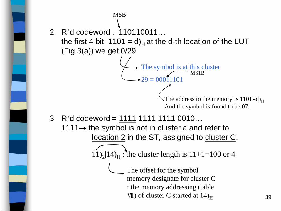
2. R’d codeword : 110110011…
the first 4 bit 1101 = d)H at the d-th location of the LUT
(Fig.3(a)) we get 0/29
3. R’d codeword = 1111 1111 1111 0010…
1111 the symbol is not in cluster a and refer to
location 2 in the ST, assigned to cluster C.
MSB
The symbol is at this cluster
29 = 00011101MS1B
The address to the memory is 1101=d)H
And the symbol is found to be 07.
The offset for the symbol
memory designate for cluster C
: the memory addressing (table
Ⅶ) of cluster C started at 14)H
11)2|14)H : the cluster length is 11+1=100 or 4

40
Our next move is to select another slice of (with length 4) from the
bit stream, which 1111 again. From the 15th location of the LUT
for cluster C we get 1/5
we move to the 15th location in the LUT for cluster f. Here we find
1/6 and refer to the 6th item in the ST.
The data here is read 00)2 and 3a)H
00 CL of cluster g is 00+1=01 ; or 1
3a)H the memory location offset of cluster g.
The symbol is not in cluster C
Location 5 of the ST cluster f
The content is 11)2 2a)H
11+1 = 100 : or 4 : cluster length
2a)H : the offset of memory location of cluster f
The symbol is not located yet, we have to choose
another 4 bit slice from the bit stream : 1111

41
Take 1 bit from the bit stream which is “0” referring the LUT of
cluster g, location “0” gives 0/2
So the symbol is in cluster g, and 2 = 00000010
(i) MS1B is located at location 1 CL = 1
(ii) to the right of MS1B is a single 0 identifying the codeword, and
(iii) the symbol (1e) is at location 3a+0 = 3a in the memory (tableⅦ)
The overall codeword is given as
1111, 1111, 1111, 0, with CL = 4+4+4+1 = 13
42
Remarks:
1. For high probable symbols with short codewords (4
bits or less) the search for the symbol is very fast,
and is completed in the first try. For longer
codewords, however, the search time grows almost
proportional to the codeword length.
If CL is the codeword length
L is the maximum level selected for each cluster
( L = 4 in the above example) then the search time is
closely proportional to 1+CL/L
2. Increasing L:
i. Decreasing search time speed up decoding
ii. Growing the memory space requirement
Trade-off
43
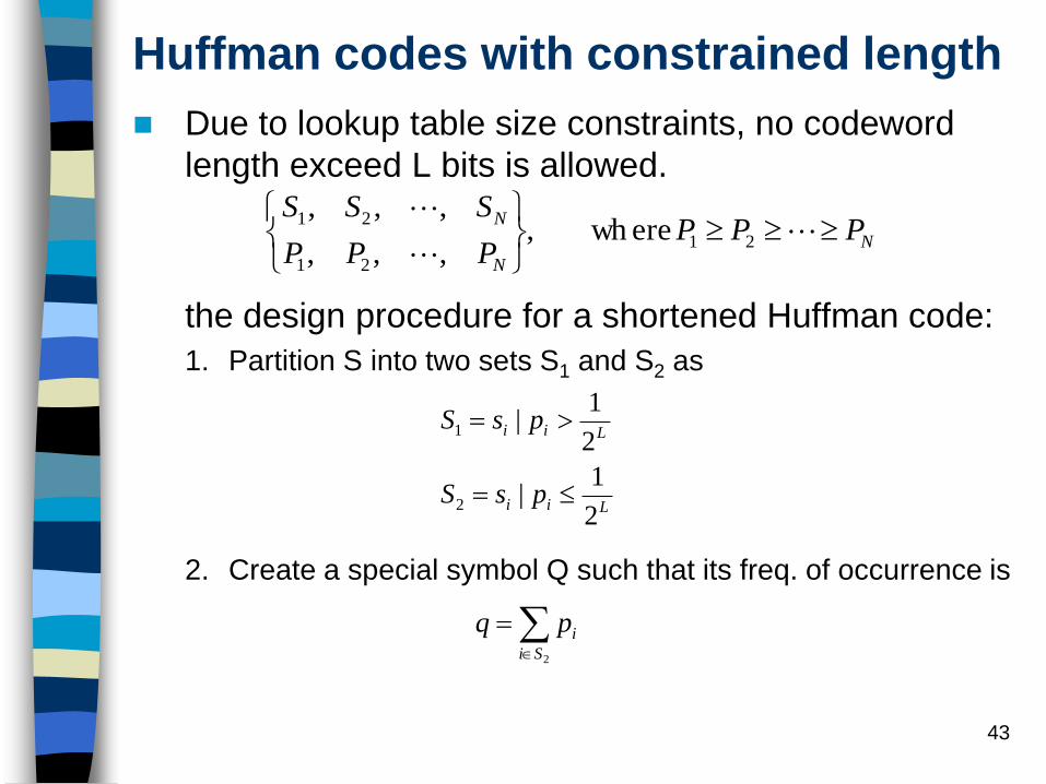
Huffman codes with constrained length
Due to lookup table size constraints, no codeword
length exceed L bits is allowed.
the design procedure for a shortened Huffman code:
1. Partition S into two sets S1 and S2 as
2. Create a special symbol Q such that its freq. of occurrence is
N
N
NPPP
PPP
SSS
21
21
21 ere wh,
,,,
,,,
Lii
Lii
psS
psS
2
1|
2
1|
2
1
2Si
ipq
44
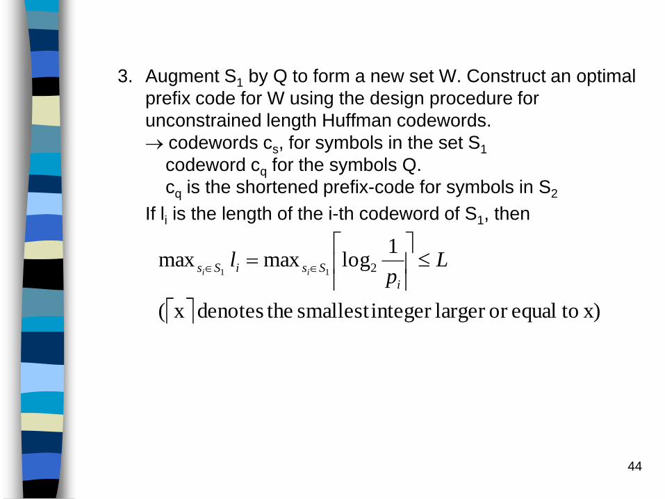
3. Augment S1 by Q to form a new set W. Construct an optimal
prefix code for W using the design procedure for
unconstrained length Huffman codewords.
codewords cs, for symbols in the set S1
codeword cq for the symbols Q.
cq is the shortened prefix-code for symbols in S2
If li is the length of the i-th codeword of S1, then
x) toequalor larger integer smallest thedenotes x(
1logmaxmax 211
Lp
li
SsiSs ii

45
Encoding : input message string m1,m2,…,mk
For all miS1, output the corresponding codeword
from .
For all miS2, output the codeword cq followed by an
L-bit fixed-length binary representation for mi.
(Actually, one can use fewer than L bits, since if there
are symbols in S2 and , then the fixed-
length binary representation for each mi is
bits).
1sC
2sN NNs 2
log22 sN

46
Let lsh be the average codeword length for the shortened codes.
lw be the average codeword length for W.
The worst-case increase in the average codeword length for the
shortened code is bits per symbol (this function attains a
maximum value of ½ ).
5.1
11
log)(
11
log1
log1
log11
log
1log
2
1log
1
1
1log
1log
1log
1log
2
2222
22
22
22
212
222
21
1
sHlavesH
qqsH
pp
pp
ppwHlsH
pppLpqL
qLwHlsH
wHlwH
qLll
wHp
pp
psH
ppwH
Si i
i
Si i
i
Si i
ish
Si i
i
SiLi
Si
i
sh
w
wsh
Si i
i
Si i
i
Si i
i
1log2
47
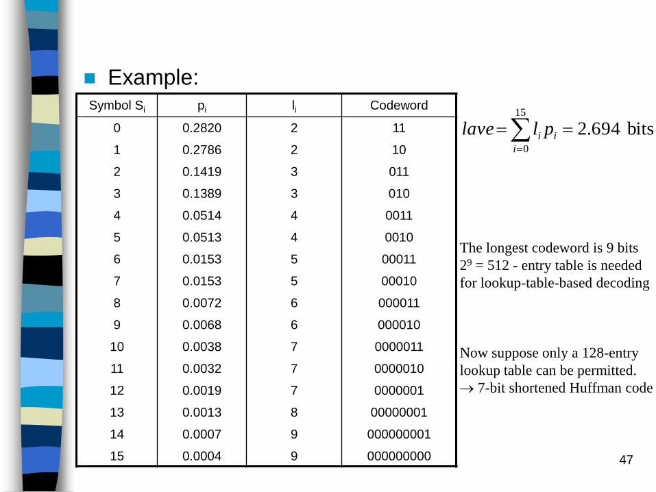
Example:Symbol Si pi li Codeword
0 0.2820 2 11
1 0.2786 2 10
2 0.1419 3 011
3 0.1389 3 010
4 0.0514 4 0011
5 0.0513 4 0010
6 0.0153 5 00011
7 0.0153 5 00010
8 0.0072 6 000011
9 0.0068 6 000010
10 0.0038 7 0000011
11 0.0032 7 0000010
12 0.0019 7 0000001
13 0.0013 8 00000001
14 0.0007 9 000000001
15 0.0004 9 000000000
bits 694.215
0
i
ii pllave
The longest codeword is 9 bits
29 = 512 - entry table is needed
for lookup-table-based decoding
Now suppose only a 128-entry
lookup table can be permitted.
7-bit shortened Huffman code

48
Code construction
1.
0253.0
15. to8ifor since ,,,
,,
15
8
1281
15982
7101
i
i
i
Pq
PsssS
sssS
S0 S1 S2 S3 S4 S5 S6 S7 Q
11 01 101 100 0011 0010 00011 00010 0000
0.2820 0.2786 0.1419 0.1389 0.0514 0.0513 0.0153 0.0153 0.0253

49
Symbol i pi li Codeword Additional
0 0.2820 2 11
1 0.2786 2 01
2 0.1419 3 101
3 0.1389 3 100
4 0.0514 4 0011
5 0.0513 4 0010
6 0.0153 5 00011
7 0.0153 5 00010
8 0.0072 11 0000 0001000
9 0.0068 11 0000 0001001
10 0.0038 11 0000 0001010
11 0.0032 11 0000 0001011
12 0.0019 11 0000 0001100
13 0.0013 11 0000 0001101
14 0.0007 11 0000 0001110
15 0.0004 11 0000 0001111

50
2. For all symbols in S2 we need a prefix code of 4 bits
followed by a 7-bit representation for the specific
symbol in S2
bits 8057.21115
8
7
0
i
i
i
iish ppll

51
Decoding:
1. We first construct a lookup table as described above.
2. From the input bit stream, we fetch bits into a buffer until the buffer
has 7 bits. We access the lookup table location, using the 7 bits as
an address.
This lookup table location contains (mk, lk)
3. The first lk bits in the buffer are discarded by shifting the buffer
contents to the left by lk bits positions.
If mk Q, mk{S0, S1,…S7}, and thus we have correctly decoded this
symbol
If mk = Q, additional bits from the input bit stream are needed for
decoding. We fetch lk bits from the bit stream to fill up the buffer. The
buffer now contains the binary representation for one of the symbols S8,
S9,…S15, and thus we have correctly decoded a symbol from S2.
4. Repeat steps 2 and 3 until the complete message has been
decoded.

52
The key disadvantage of two-level decoding is that we
cannot guarantee a constant symbol rate at the
Huffman decoder output.
Lookup table size (entries) Worst case lsh-lave (bits/symbol)
16 0.4213
32 0.2326
64 0.2326
128 0.1342
256 0.0731
512 0.0338

53
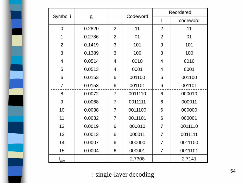
Constrained-length Huffman codes: prefix-free constant
output decoding rate with a table-lookup decoder
For a maximum codeword length of L bits, we define a threshold
T = 2-L
Sort si, i = 1, 2, …, N so that pk pk+1
For each pi, if pi T, set pi = T
Design the codebook using the modified pi values and the
unconstrained-length Huffman code table design approach
Since pi is restricted to at most 2-L, no codeword length will
exceed L bits.
Codeword length 1/ pi : not guarantee
This is due to the fact that some of the properties were set to the
threshold T and hence the ordering among the properties is
obscured.
Rearranging is done by simply sorting the codeword lengths in
ascending order of magnitude and associating this sorted list to
the corresponding list of codewords.
54
Symbol i pi l CodewordReordered
l codeword
0 0.2820 2 11 2 11
1 0.2786 2 01 2 01
2 0.1419 3 101 3 101
3 0.1389 3 100 3 100
4 0.0514 4 0010 4 0010
5 0.0513 4 0001 4 0001
6 0.0153 6 001100 6 001100
7 0.0153 6 001101 6 001101
8 0.0072 7 0011110 6 000010
9 0.0068 7 0011111 6 000011
10 0.0038 7 0011100 6 000000
11 0.0032 7 0011101 6 000001
12 0.0019 6 000010 7 0011110
13 0.0013 6 000011 7 0011111
14 0.0007 6 000000 7 0011100
15 0.0004 6 000001 7 0011101
lave 2.7308 2.7141
: single-layer decoding

55
Constrained-length Huffman codes: The Voorhis method [1974, IEEE Trans. IT]: near optimum codeword length
Determine code lengths l1, l2,…, lN that minimize subject to
the constraints 1li L. For unique decodable codes, we also
require that . The resulting codeword lengths will be such
that 1 l1 l2 … lN L
The I-th codeword is the first li bits of the fraction computed by
.
For an N-symbol alphabet, if L=log2N+d, then this method has a
complexity of O(dN2).
N
N
NPPP
PPP
SSS
21
21
21 and ,
,,,
,,,
N
i
ii pl
12
N
i
li
1
1
2i
k
lk
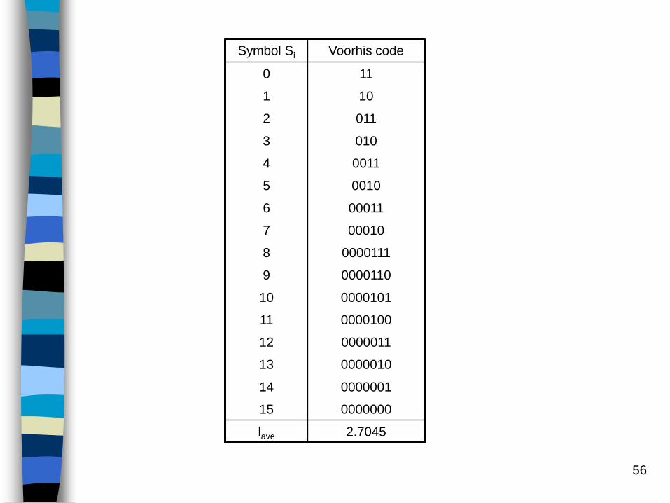
56
Symbol Si Voorhis code
0 11
1 10
2 011
3 010
4 0011
5 0010
6 00011
7 00010
8 0000111
9 0000110
10 0000101
11 0000100
12 0000011
13 0000010
14 0000001
15 0000000
lave 2.7045

57
Home Work:
1. Consider codes that satisfy the suffix condition, which says that no codeword is a suffix of any other codeword. Show that a suffix condition code is uniquely decodable, and show that the minimum average length over all codes satisfying the suffix condition is the same as the average length of the Huffman code for that random variable.
Suffix code
2. Suppose that X=i with probability Pi, i=1, 2, …m. Let libe the number of binary symbols in the codeword associated with X=i, and let ci denote the cost per letter of the codeword when X=i. Thus the average cost C of the description of X is
m
i
iii lcpC1

58
a) Minimize C over all l1,l2,…,lm such that 2-li1. Ignore any
implied integer constraints on li. Exhibit the minimizing
l1*,l2
*,…,lm* and the associated minimum value C*.
b) How would you use the Huffman code procedure to minimize
C over all uniquely decodable codes? Let CHuffman denote this
minimum. Show that
Huffman codes with costs.
m
i
iiHuffman cpCCC1
**
59
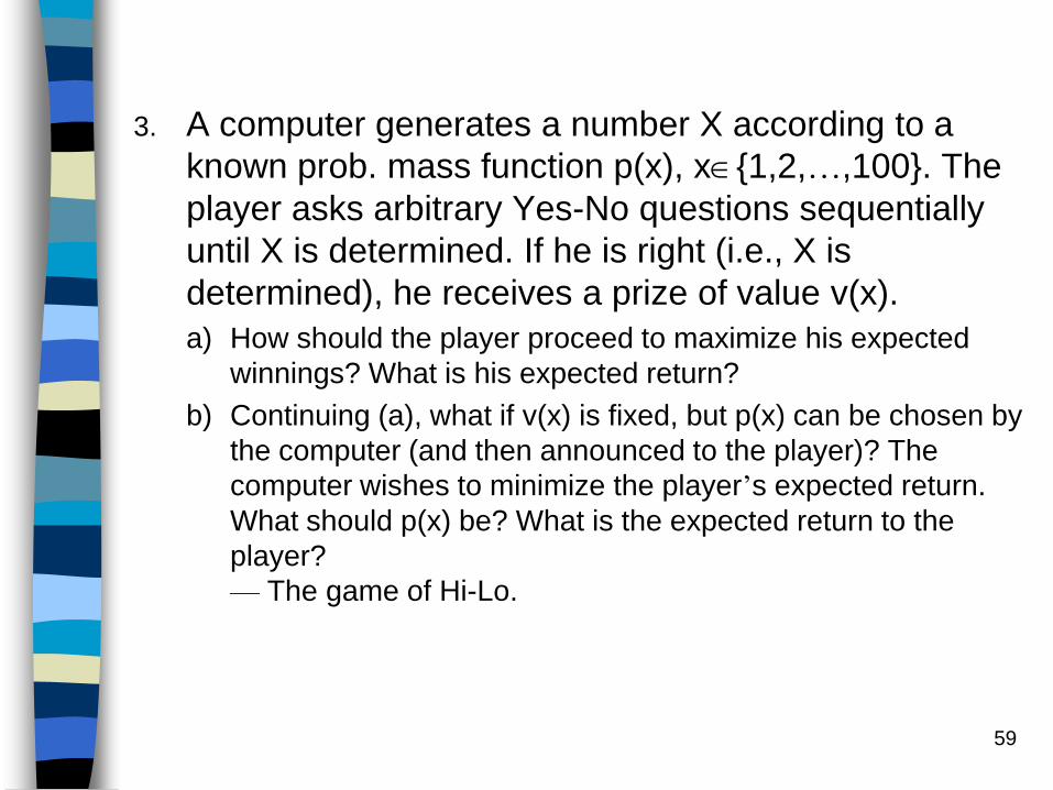
3. A computer generates a number X according to a
known prob. mass function p(x), x{1,2,…,100}. The
player asks arbitrary Yes-No questions sequentially
until X is determined. If he is right (i.e., X is
determined), he receives a prize of value v(x).
a) How should the player proceed to maximize his expected
winnings? What is his expected return?
b) Continuing (a), what if v(x) is fixed, but p(x) can be chosen by
the computer (and then announced to the player)? The
computer wishes to minimize the player’s expected return.
What should p(x) be? What is the expected return to the
player?
— The game of Hi-Lo.

60
4. Although the codeword lengths of an optimal variable
length code are complicated functions of the
message probabilities {p1,p2,…,pm}, it can be said that
less probable symbols are encoded into longer
codewords. Suppose that the message probabilities
are given in decreasing order p1p2 … pm.
a) Prove that for any binary Huffman code, if the most probable
message symbol has probability p1>2/5, then that symbol
must be assigned a codeword of length 1.
b) Prove that for any binary Huffman code, if the most probable
message symbol has probability p1<1/3, then that symbol
must be assigned a codeword of length 2.


