Grommet type IO-Link device compatible
IP67 IP67
∗1 When pin #2 is set to PNP input and pin #4 is set to PNP input (M12 connector)
∗2 When pin #2 is set to PNP output and pin #4 is set to PNP input (M12 connector)
PNP 16 inputs PNP 16 outputs
· SIO mode∗1
PNP 8 inputs· IO-Link mode
4 port
· SIO mode∗2
PNP 4 inputs
PNP 4 outputs· IO-Link mode
4 port
Input type Output type
Wireless System
Compact Remote
∗1 For the e-CON typeCompared with the existing remote, M8 connector/digital 8 inputs specification
Compact
Approx. 61 % reduction∗1Area
Approx. 86 % reduction∗1Volume
Lightweight
Approx. 87 % reduction∗1Weight
PLC PC
BaseB
Base side Remote side
Wireless remote
I/O unitEnd plate (Power supply/U side)
One unit
EX600-W
[mm]
Trademark
EtherNet/IP™ is a trademark of ODVA.
Reduceslabourtime
Compactremote
Existingremote
Applicable to existing wireless systems
Wireless remote
I/O unitEnd plate (Power supply)
Existing remote
End plate (U side)
Products should be ordered separately
and assembled by the customer.
146
100
59.8
20.3
106
73.6
�VariationsG
P 16 inputs
pe
IP
16 outputs
IO-Link dev
#2 is set to PNP input and pin #4
∗1
uts
ode
e
ble
IP67
t (M12 t )
2
ts
puts
de
e
Countries/Regions in which wireless is supportedThis product cannot be used in countries where wireless is not supported. Refer
to the back cover for details on countries in which the product can be used.
155 cm2 a 59.8 cm2
1,139 cm3 a 159 cm3
965 g a 130 g
NewNew
INFORMATION
EX600-W Series20-EU750-UK
Specifi cations
Wireless Communication SpecificationsProtocol SMC original protocol
Radio wave type Frequency Hopping Spread Spectrum (FHSS)
Frequency 2.4 GHz (2403 to 2481 MHz)
Number of frequency channels 79 ch (Bandwidth: 1.0 MHz)
Communication speed 250 kbps
Communication distance 10 m (Depending on the operating environment)
Radio Law certificate Refer to page 8
IO-Link Communication Specifications∗1
Communication speed
COM1 (4.8 kBaud)
COM2 (38.4 kBaud)
COM3 (230.4 kBaud)
Automatically switched according to the device to be connected
Ports for IO-Link devices 4∗2
∗1 Parameter setting for IO-Link devices is not supported. Set using the
dedicated tool before connecting the product.
∗2 Only process data can be sent and received.
General Specifications
Type
e-CON type Grommet type IO-Link device compatible
PNP input
EX600-WDXE1PNP output
EX600-WDYE1PNP input
EX600-WDXA1PNP output
EX600-WDYA1PNP input
EX600-WLXB1PNP output
EX600-WLYB1
Power supply for control
and input (US1)
Power supply voltage 24 VDC ±10 %
Current consumption∗1 100 mA or less 50 mA or less 100 mA or less 50 mA or less 100 mA or less 100 mA or less
Power supply
for output
(US2)
Power supply voltage
—
24 VDC ±10 %
—
24 VDC ±10 %
—
24 VDC ±10 %
Max. load current
(per unit)800 mA 2 A∗2 2 A∗2
Max. load current
(per output)
100 mA
(per output)
100 mA
(per output)
100 mA
(per output)
Electrical
specifications
(Common)
Number of points8 inputs
(1 input/connector)
8 outputs
(1 output/connector)
16 inputs
(2 inputs/connector)
16 outputs
(2 outputs/connector)
8 inputs
(2 inputs/connector)∗34 outputs
(1 output/connector)∗3
Type PNP (-COM)
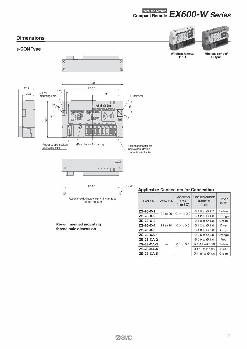
Connector type e-CON (4-pin) M12 5-pin socket (Female)
Max. sensor supply current 2 A/unit, 0.3 A/connector 2 A/unit, 0.3 A/connector 1 A/unit, 0.3 A/connector
Input
Input resistance 1.5 kΩ
—
1.5 kΩ
—
— —
Rated input
current5 mA or less 5 mA or less
2.5 mA or less
(Pin #2)
5.5 mA or less
(Pin #4)
5.5 mA or less
(Pin #4)
Signal OFF-judgement 5 VDC/2 mA or less 5 VDC/2 mA or less 5 VDC/2 mA or less —
Signal ON-judgement 15 VDC/5 mA or more 15 VDC/5 mA or more 15 VDC/5 mA or more —
Protection Short-circuit protection Short-circuit protection Short-circuit protection
OutputMax. load current —
100 mA
(per output)—
100 mA
(per output)—
100 mA
(per output)
Protection — Short-circuit protection — Short-circuit protection — Short-circuit protection
Cable tensile strength 10 N 100 N
Operating ambient temperature 0 to +50°CStorage ambient temperature −10 to +60°CAmbient humidity 35 to 85 %RH
Withstand voltage 10 MΩ or more (500 VDC between external terminals and metallic parts)
Insulation resistance 500 VAC for 1 minute between external terminals and metallic parts
Vibration resistance Compliant with EN61131-2, 5 ≤ f < 8.4 Hz 3.5 mm, 8.4 ≤ f < 150 Hz 9.8 m/s2
Impact resistance Compliant with EN61131-2, 147 m/s2, 11 ms
Enclosure IP20 IP67
Mounting M4 screw through hole 2 locations M5 screw through hole 4 locations M4 screw through hole 2 locations
Weight 130 g 480 g 230 g
∗1 When an external device is not connected (Body only)
∗2 (Per unit) See the output specifications for the load current for each signal.
∗3 Max. number of points when set to SIO-mode
∗ Number of connections when the setting enabling IO-Link devices is selected
1
EX600-W Series
Recommended screw tightening torque:
1.35 to 1.65 N·m
100
90.8 ±0.1
45
59.8
90.8 ±0.8 2 x M4
26.7
20.3FG terminal
20
Push button for pairingSocket connector for
input/output device
connection (4P x 8)
4.5
6.4
ø4.5
2 x (R)
2 x M4
mounting hole
Power supply socket
connector (4P)
Dimensions
e-CON TypeWireless remote/
Input
Wireless remote/
Output
Recommended mounting
thread hole dimension
Applicable Connectors for Connection
Part no. AWG No.
Conductor
area
[mm SQ]
Finished outside
diameter
[mm]
Cover
color
ZS-28-C-124 to 26 0.14 to 0.2
Ø 1.0 to Ø 1.2 Yellow
ZS-28-C-2 Ø 1.2 to Ø 1.6 Orange
ZS-28-C-3
22 to 20 0.3 to 0.5
Ø 1.0 to Ø 1.2 Green
ZS-28-C-4 Ø 1.2 to Ø 1.6 Blue
ZS-28-C-5 Ø 1.6 to Ø 2.0 Grey
ZS-28-CA-1
— 0.1 to 0.5
Ø 0.6 to Ø 0.9 Orange
ZS-28-CA-2 Ø 0.9 to Ø 1.0 Red
ZS-28-CA-3 Ø 1.0 to Ø 1.15 Yellow
ZS-28-CA-4 Ø 1.15 to Ø 1.35 Blue
ZS-28-CA-5 Ø 1.35 to Ø 1.6 Green
2
Wireless System
Compact Remote EX600-W Series
Power supply
for control/input
24 VDC
Power supply socket
1-pin
24 V
2-pin
N.C.
3-pin
GND
4-pin
N.C.
1-pin
24 V
2-pin
N.C.
3-pin
GND
4-pin
Input
FE
1.5 kΩ
(US1)
(US1)
(US1)
Internal circuit
Short-circuit detection
Socket for input device
connection x 8
(0 to 7)
Power supply
for control/input
24 VDC
Power supply
for output
24 VDC
Power supply socket
1-pin
24 V
2-pin
24 V
3-pin
GND
4-pin
GND
1-pin
N.C.
2-pin
N.C.
3-pin
GND
4-pin
Output
FE
(US1)
(US2)
(US1)
(US2)
Internal circuit
Short-circuit detection
Socket for output device
connection x 8
(0 to 7)
Socket for output device
connection x 8 (0 to 7)
Socket for input device
connection x 8 (0 to 7)
Output
Input
e-CON Type/Connector Specifications (Input/Output)
Wireless remote/Input
Wireless remote/Output
Power supply socket connector wiring specifications
Socket connector for input device connection wiring specifications
Socket connector for output device connection wiring specifications
q
w
e
r
q
w
e
r
q
w
e
r
q
w
e
r
Pin no. Terminal name
1 24 V (For control/input)
2 N.C.
3 0 V (For control/input)
4 N.C.
Pin no. Terminal name
1 24 V (For control/input)
2 24 V (For output)
3 0 V (For control/input)
4 0 V (For output)
Pin no. Terminal name
1 24 V (For control/input)
2 N.C.
3 0 V (For control/input)
4 IN
Pin no. Terminal name
1 N.C.
2 N.C.
3 0 V (For output)
4 OUT
3
EX600-W Series
(370)
(310)
(250)
(190)
(130)Recommended screw
tightening torque: 2.7 to 3.3 N·m
4 x M5
90 ±1
72
±1
6.2
Section A
Section A With short jumper connected
8.2
8.2
6.2
6.2
6.2FG terminal
8.2
Labeling
(340)
(280)
(220)
(160)
90 ±0.2
15
8.2
(105)
15
72
±0.2
(85
)
2.5
29.575 (100)
Dimensions
Recommended mounting
thread hole dimensions
Grommet TypePNP 16 inputs PNP 16 outputs
4
Wireless System
Compact Remote EX600-W Series
Power supply
for control/input
24 VDC
Power supply cable
1-pin
24 V
2-pin
Input 2
5-pin
N.C.
3-pin
GND
4-pin
Input 1
1-pin
24 V
1-pin N.C.
2-pin N.C.
3-pin
4-pin
2-pin
N.C.
3-pin
GND
4-pin
N.C.
FE
(US1)
(US1) (US1)
Short
jumper Internal circuit
Short-circuit detection
Input cable x 8
(0 to F)
Pairing cable
1.5 kΩ
1.5 kΩ
Power supply
for control/input
24 VDC
Power supply cable
1-pin
N.C.
2-pin
Output 2
5-pin
N.C.
3-pin
GND
4-pin
Output 1
1-pin
24 V
1-pin N.C.
2-pin N.C.
3-pin
4-pin
2-pin
24 V
3-pin
GND
4-pin
GND
FE
(US1)
(US1) (US2)
(US2)
Short
jumper
Power supply
for output
24 VDC
Internal circuit
Short-circuit detection
Output cable x 8
(0 to F)
Input cable x 8 (0 to F)
Output cable x 8 (0 to F)
Output
Input
PNP 16 inputs
PNP 16 outputs
Grommet Type/Connector Specifications (Input/Output)
Connector Arrangement Specifications
No. DescriptionCable length
[mm]Labelling
Cable with M12
connector
5
7
98
6
4
23
01
0 Pairing line 100 PAIRING M12, 4-pin,
plug (Male)1 Power supply line 130 POWER
2 Input E/F 160 E/F
M12, 5-pin,
socket
(Female)
3 Input C/D 190 C/D
4 Input A/B 220 A/B
5 Input 8/9 250 8/9
6 Input 6/7 280 6/7
7 Input 4/5 310 4/5
8 Input 2/3 340 2/3
9 Input 0/1 370 0/1
Connector Arrangement Specifications
No. DescriptionCable length
[mm]Labelling
Cable with M12
connector
5
7
98
6
4
23
01
0 Pairing line 100 PAIRING M12, 4-pin,
plug (Male)1 Power supply line 130 POWER
2 Output E/F 160 E/F
M12, 5-pin,
socket
(Female)
3 Output C/D 190 C/D
4 Output A/B 220 A/B
5 Output 8/9 250 8/9
6 Output 6/7 280 6/7
7 Output 4/5 310 4/5
8 Output 2/3 340 2/3
9 Output 0/1 370 0/1
Connector Specifications
Labelling PAIRING POWER 0/1 to E/F M12, 4-pin plugM12, 5-pin
socket
Pin no. Description
2
3 4
1
5
1
4 3
21Short jumper
Connected:
Normal mode
(3-pin to 4-pin
short)
Not connected:
Pairing mode
Power supply for control: + (COM)
2 N.C. Input n + 1
3Power supply
for control: − (COM)
Power supply for control: − (COM)
4 N.C. Input n
5 — — N.C.
Connector Specifications
Labelling PAIRING POWER 0/1 to E/F M12, 4-pin plugM12, 5-pin
socket
Pin no. Description
2
3 4
1
5
1
4 3
2
1Short jumper
Connected:
Normal mode
(3-pin to 4-pin
short)
Not connected:
Pairing mode
Power supply for control: + (COM)
N.C.
2Power supply
for output: + (COM)
Output n + 1
3Power supply
for control: − (COM)
Power supply for output: − (COM)
4Power supply
for output: − (COM)
Output n
5 — — N.C.
5
EX600-W Series
Recommended screw tightening torque:
1.35 to 1.65 N·m
2 x M4
45
FG terminal
2 x (R)
2 x M4 mounting hole
4.5
6.4
ø4.5
(255)
(225)
(195)
(165)
(135)
71
55
20
90
.8 ±0
.1
10
0
5
14
.5
20
.3
90
.8 ±0
.8
Dimensions
Recommended mounting
thread hole dimensions
Grommet Type for IO-Link DeviceInput type Output type
6
Wireless System
Compact Remote EX600-W Series
Connector Arrangement Specifications
No. DescriptionCable length
[mm]Labelling Type
1 PORT1 255 —M12, 5-pin,
socket,
A-coded
2 PORT2 225 —
3 PORT3 195 —
4 PORT4 165 —
5Power supply
IN connector135 POWER
M12, 4-pin,
plug,
A-coded
6Power supply
OUT connector— —
M12, 5-pin,
socket,
A-coded
Connector Arrangement Specifications
No. DescriptionCable length
[mm]Labelling Type
1 PORT1 255 —M12, 5-pin,
socket,
A-coded
2 PORT2 225 —
3 PORT3 195 —
4 PORT4 165 —
5Power supply
IN connector135 POWER
M12, 4-pin,
plug,
A-coded
6Power supply
OUT connector— —
M12, 5-pin,
socket,
A-coded
IO ConnectorPin no. Description M12, 5-pin, socket, A-coded
1 L+ (US1)1
4 3
2
5
2 DI (Digital input)
3 L− (US1)
4 CQ (IO-Link)∗1
5 Not used
∗1 Switchable to IO-Link/digital input (PNP input)
IO ConnectorPin no. Description M12, 5-pin, socket, A-coded
1 L+ (US1)1
4 3
2
5
2 DO (Digital output)
3 L− (US1)
4 CQ (IO-Link)∗1
5 0 V (US2)
∗1 Switchable to IO-Link/digital input (PNP input)
Power Supply IN ConnectorPin no. Description M12, 4-pin, plug, A-coded
1 24 V (US1) 2
3 4
1
2 24 V (US2)
3 0 V (US1)
4 0 V (US2)
Power Supply IN ConnectorPin no. Description M12, 4-pin, plug, A-coded
1 24 V (US1) 2
3 4
1
2 24 V (US2)
3 0 V (US1)
4 0 V (US2)
Power Supply OUT ConnectorPin no. Description M12, 5-pin, socket, A-coded
1 24 V (US1)1
4 3
2
5
2 24 V (US2)
3 0 V (US1)
4 0 V (US2)
5 Not used
Power Supply OUT ConnectorPin no. Description M12, 5-pin, socket, A-coded
1 24 V (US1)1
4 3
2
5
2 24 V (US2)
3 0 V (US1)
4 0 V (US2)
5 Not used
Input
Output
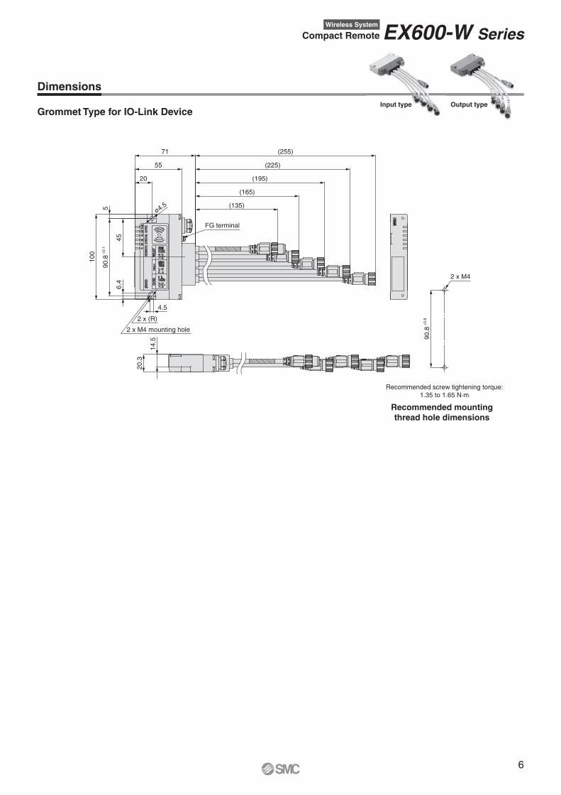
Grommet Type for IO-Link Device/Connector SpecificationsInput type
Output type
7
EX600-W Series
EX600-W Series
Important
Warning� The product is certifi ed as a wireless equipment in accordance with the Radio Act and the Japanese radio law has been obtained. Customers do not need
to apply for a license to use this equipment.Be sure to comply with the following precautions. · Do not disassemble or modify the product. Disassembly and modifi cation are prohibited by law. · This product is for use in Japan, European countries (Austria, Belgium, Bulgaria, Croatia, Czech Republic, Denmark, Estonia, Finland, France,
Germany, Greece, Hungary, Ireland, Italy, Latvia, Lithuania, Netherlands, Norway, Poland, Portugal, Romania, Slovakia, Slovenia, Spain, Sweden, Switzerland, U.K., Turkey), the U.S. and Canada. For use in other countries, please contact SMC.
� This product communicates by radio waves, and the communication may stop instantaneously due to ambient environments and operating methods.SMC will not be responsible for any secondary failure which may cause personal injury, or damage to other devices or equipment.
�When several units are installed closely to each other, slight interference may occur due to the characteristics of the wireless product.� The electromagnetic waves emitted from this product may interfere with implantable medical devices such as cardiac pacemakers and cardioverter
defi brillators, resulting in the malfunction of the medical device or other adverse effects.Please use extreme caution when operating equipment which may have an adverse effect on your implantable medical device. Be sure to thoroughly read the precautions stated in the catalogue, operation manual, etc., of your implantable medical device, or contact the manufacturer directly for further details on what types of equipment need to be avoided.
�The communication performance is affected by the ambient environment, so please perform the communication testing before use.
∗ As of end of September, 2020
8
Specifications are subject to change without prior notice and any obligation on the part of the manufacturer.
SMC CORPORATION Akihabara UDX 15F, 4-14-1, Sotokanda, Chiyoda-ku, Tokyo 101-0021, JAPAN Phone: 03-5207-8249 FAX: 03-5298-5362
SMC Corporation (Europe)
1st printing ZZ printing ZZ 00 Printed in Spain
Lithuania +370 5 2308118 www.smclt.lt [email protected] +31 (0)205318888 www.smc.nl [email protected] +47 67129020 www.smc-norge.no [email protected] +48 222119600 www.smc.pl [email protected] +351 214724500 www.smc.eu [email protected] +40 213205111 www.smcromania.ro [email protected] +7 8123036600 www.smc.eu [email protected] +421 (0)413213212 www.smc.sk [email protected] +386 (0)73885412 www.smc.si [email protected] +34 945184100 www.smc.eu [email protected] +46 (0)86031200 www.smc.nu [email protected] +41 (0)523963131 www.smc.ch [email protected] +90 212 489 0 440 www.smcpnomatik.com.tr [email protected] UK +44 (0)845 121 5122 www.smc.uk [email protected]
Austria +43 (0)2262622800 www.smc.at [email protected] +32 (0)33551464 www.smc.be [email protected] +359 (0)2807670 www.smc.bg [email protected] Croatia +385 (0)13707288 www.smc.hr [email protected] Republic +420 541424611 www.smc.cz [email protected] Denmark +45 70252900 www.smcdk.com [email protected] Estonia +372 6510370 www.smcpneumatics.ee [email protected] +358 207513513 www.smc.fi [email protected] +33 (0)164761000 www.smc-france.fr [email protected] +49 (0)61034020 www.smc.de [email protected] +30 210 2717265 www.smchellas.gr [email protected] +36 23513000 www.smc.hu [email protected] +353 (0)14039000 www.smcautomation.ie [email protected] +39 03990691 www.smcitalia.it [email protected] +371 67817700 www.smc.lv [email protected]