69
UPDATING VERMONT’S COMMERCIAL ENERGY CODE Informational Webinar for Stakeholders MARCH 12 & 14, 2014 http://publicservice.vermont.gov/topics/ energy_efficiency/code_update 1
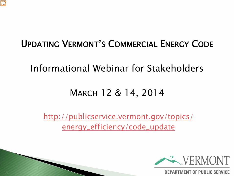
UPDATING VERMONT’S COMMERCIAL ENERGY CODE
Informational Webinar for Stakeholders
MARCH 12 & 14, 2014
http://publicservice.vermont.gov/topics/ energy_efficiency/code_update
1
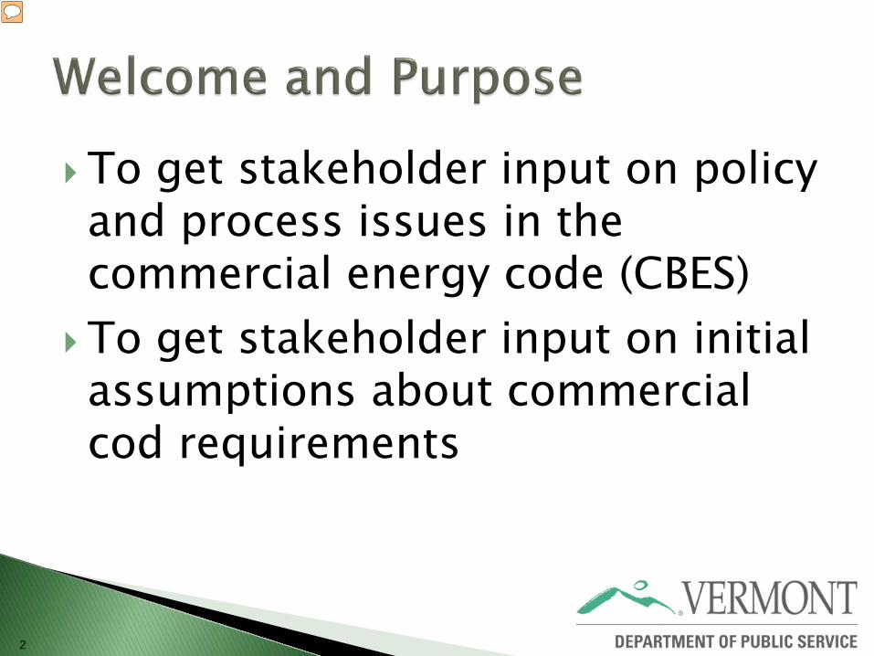
2
To get stakeholder input on policy and process issues in the commercial energy code (CBES)
To get stakeholder input on initial assumptions about commercial cod requirements
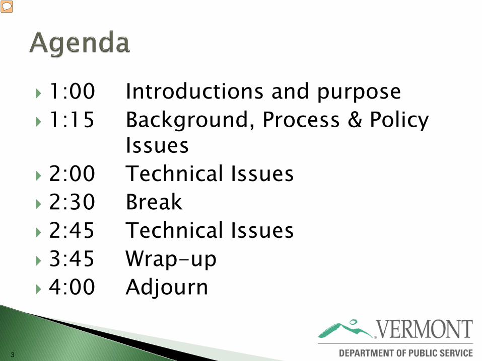
1:00 Introductions and purpose 1:15 Background, Process & Policy Issues
2:00 Technical Issues 2:30 Break 2:45 Technical Issues 3:45 Wrap-up 4:00 Adjourn
3
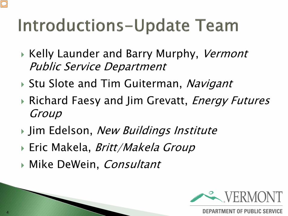
Kelly Launder and Barry Murphy, Vermont Public Service Department
Stu Slote and Tim Guiterman, Navigant Richard Faesy and Jim Grevatt, Energy Futures
Group Jim Edelson, New Buildings Institute Eric Makela, Britt/Makela Group Mike DeWein, Consultant
4
Who are you? What organization do you represent? What is your stake in the codes update?
5

6
Energy code update required by Vermont Law Residential Building Energy Standards (RBES) Commercial Building Energy Standards (CBES) Every 3 years Process managed by Public Service
Department
7
Act 89 ◦ Town administrator requirements Provide information Certificate of Occupancy tied to code
certificate ◦ Stretch code for residential Adoption by local jurisdictions; optional Act 250
8
Effective early 2015 Stakeholder meetings Spring 2014 Legislative Committee on Rulemaking
(LCAR) early fall, 2014 in order to meet target
9
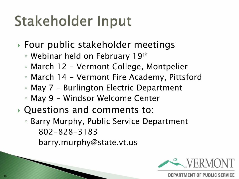
Four public stakeholder meetings ◦ Webinar held on February 19th ◦ March 12 - Vermont College, Montpelier ◦ March 14 - Vermont Fire Academy, Pittsford ◦ May 7 - Burlington Electric Department ◦ May 9 - Windsor Welcome Center
Questions and comments to: ◦ Barry Murphy, Public Service Department 802-828-3183 [email protected]
10
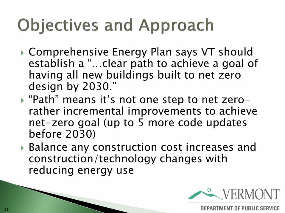
Comprehensive Energy Plan says VT should establish a “…clear path to achieve a goal of having all new buildings built to net zero design by 2030.”
“Path” means it’s not one step to net zero- rather incremental improvements to achieve net-zero goal (up to 5 more code updates before 2030)
Balance any construction cost increases and construction/technology changes with reducing energy use
11
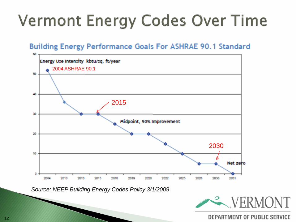
12
Source: NEEP Building Energy Codes Policy 3/1/2009
2015
2030
2004 ASHRAE 90.1
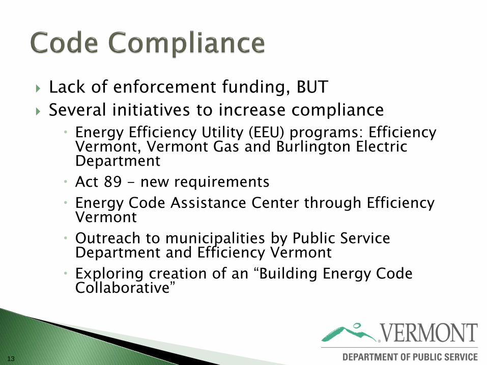
Lack of enforcement funding, BUT Several initiatives to increase compliance
Energy Efficiency Utility (EEU) programs: Efficiency Vermont, Vermont Gas and Burlington Electric Department
Act 89 - new requirements Energy Code Assistance Center through Efficiency
Vermont Outreach to municipalities by Public Service
Department and Efficiency Vermont Exploring creation of an “Building Energy Code
Collaborative”
13
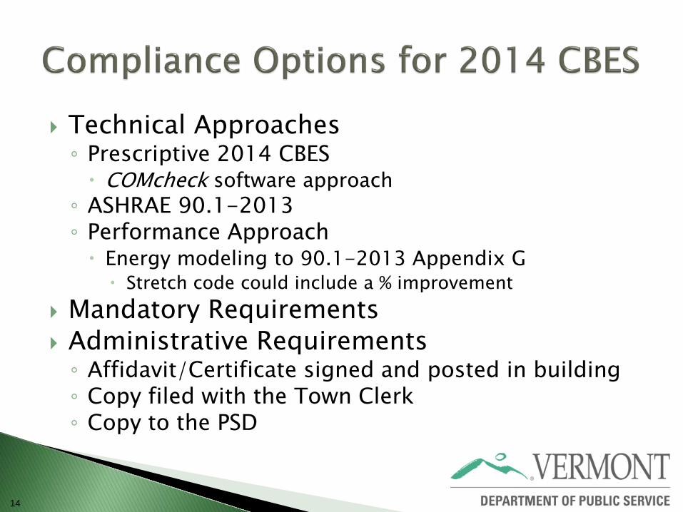
Technical Approaches ◦ Prescriptive 2014 CBES COMcheck software approach ◦ ASHRAE 90.1-2013 ◦ Performance Approach Energy modeling to 90.1-2013 Appendix G Stretch code could include a % improvement
Mandatory Requirements Administrative Requirements ◦ Affidavit/Certificate signed and posted in building ◦ Copy filed with the Town Clerk ◦ Copy to the PSD
14
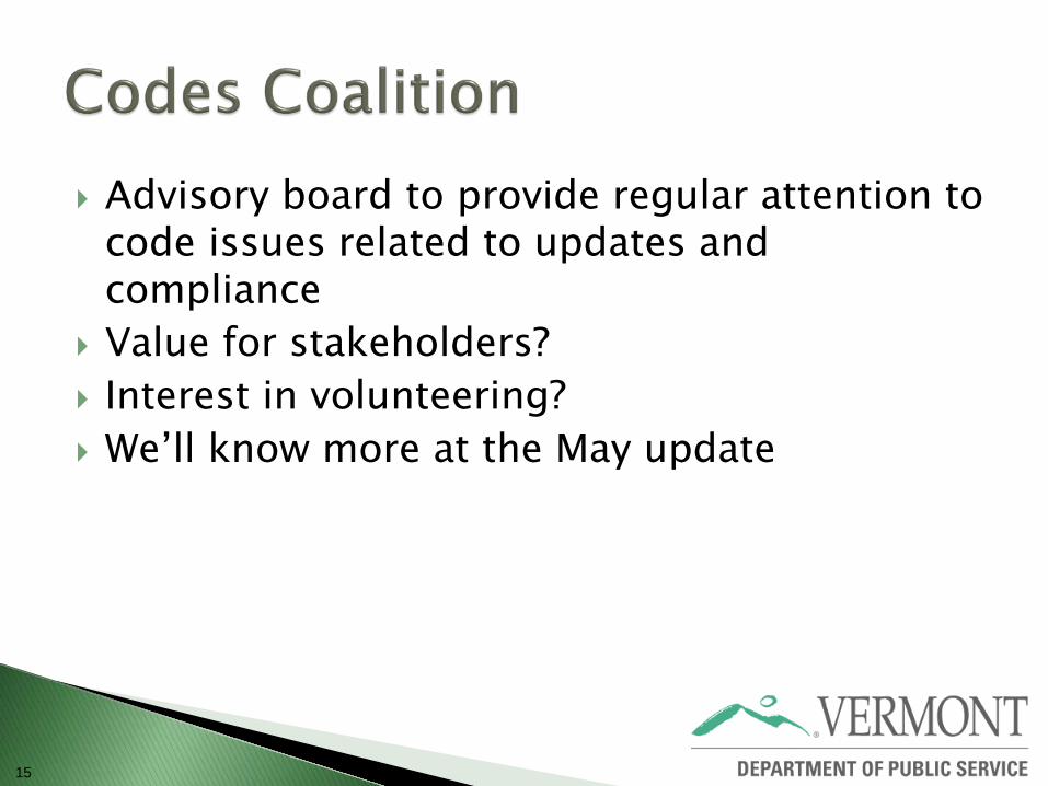
Advisory board to provide regular attention to code issues related to updates and compliance
Value for stakeholders? Interest in volunteering? We’ll know more at the May update
15
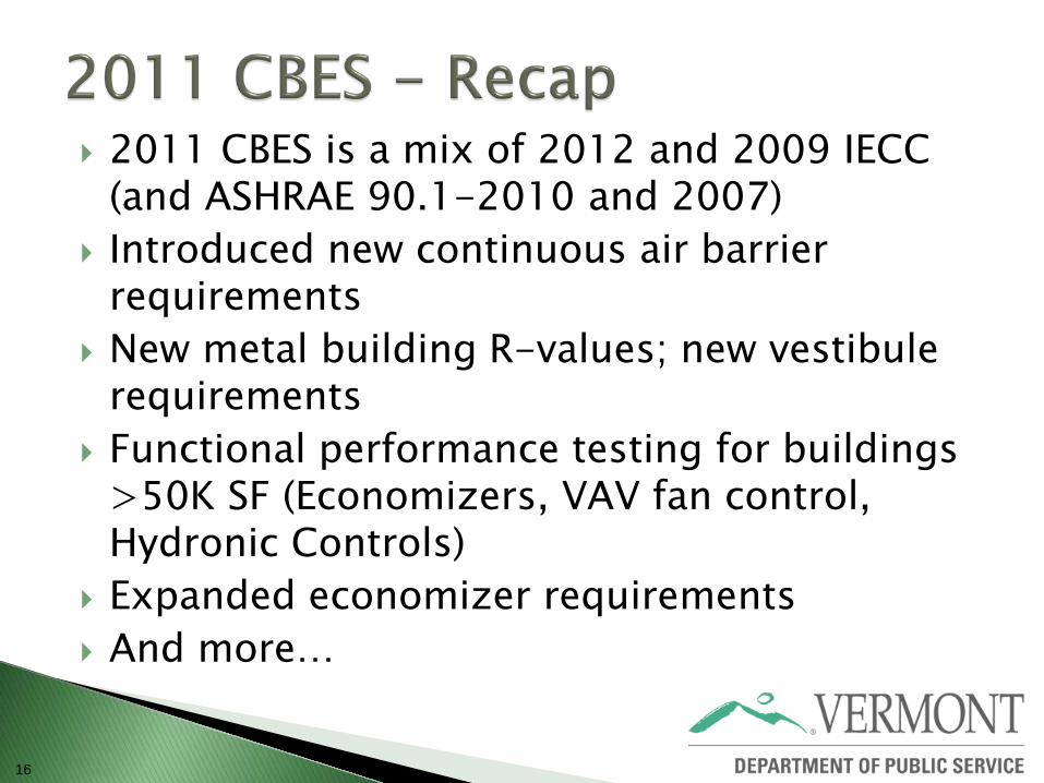
2011 CBES is a mix of 2012 and 2009 IECC (and ASHRAE 90.1-2010 and 2007)
Introduced new continuous air barrier requirements
New metal building R-values; new vestibule requirements
Functional performance testing for buildings >50K SF (Economizers, VAV fan control, Hydronic Controls)
Expanded economizer requirements And more…
16
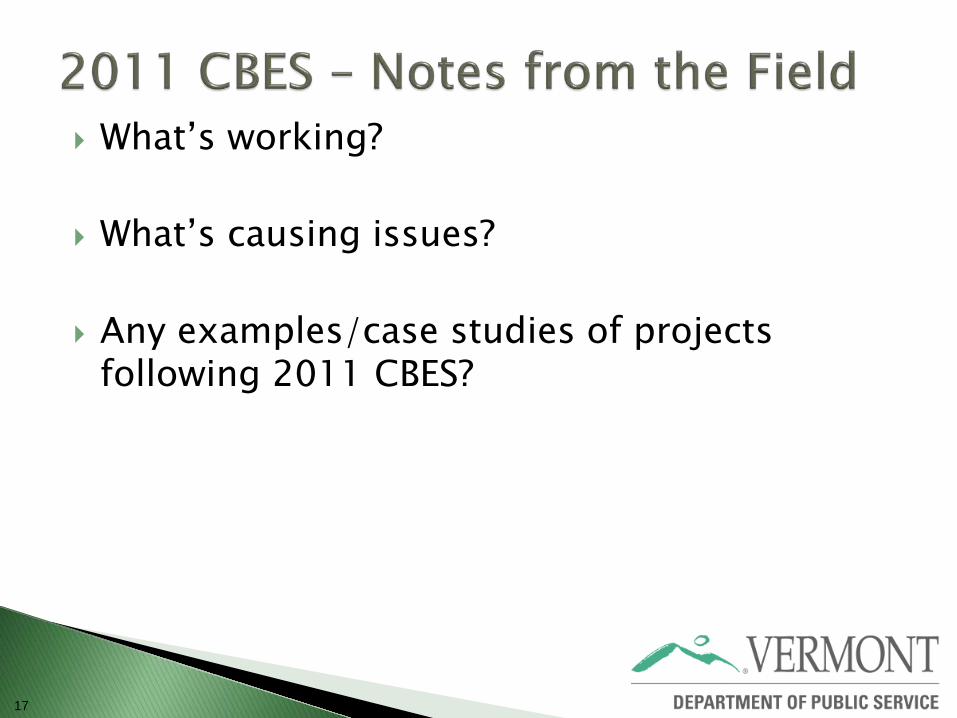
What’s working?
What’s causing issues?
Any examples/case studies of projects following 2011 CBES?
17
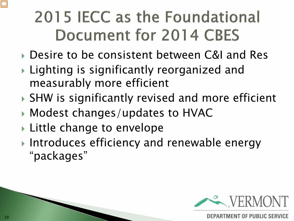
Desire to be consistent between C&I and Res Lighting is significantly reorganized and
measurably more efficient SHW is significantly revised and more efficient Modest changes/updates to HVAC Little change to envelope Introduces efficiency and renewable energy
“packages”
18
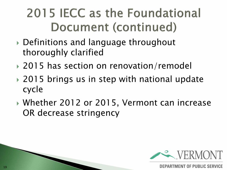
Definitions and language throughout thoroughly clarified
2015 has section on renovation/remodel 2015 brings us in step with national update
cycle Whether 2012 or 2015, Vermont can increase
OR decrease stringency
19
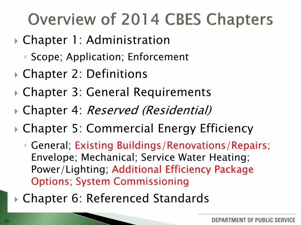
Chapter 1: Administration ◦ Scope; Application; Enforcement
Chapter 2: Definitions Chapter 3: General Requirements Chapter 4: Reserved (Residential) Chapter 5: Commercial Energy Efficiency ◦ General; Existing Buildings/Renovations/Repairs;
Envelope; Mechanical; Service Water Heating; Power/Lighting; Additional Efficiency Package Options; System Commissioning
Chapter 6: Referenced Standards 20
21
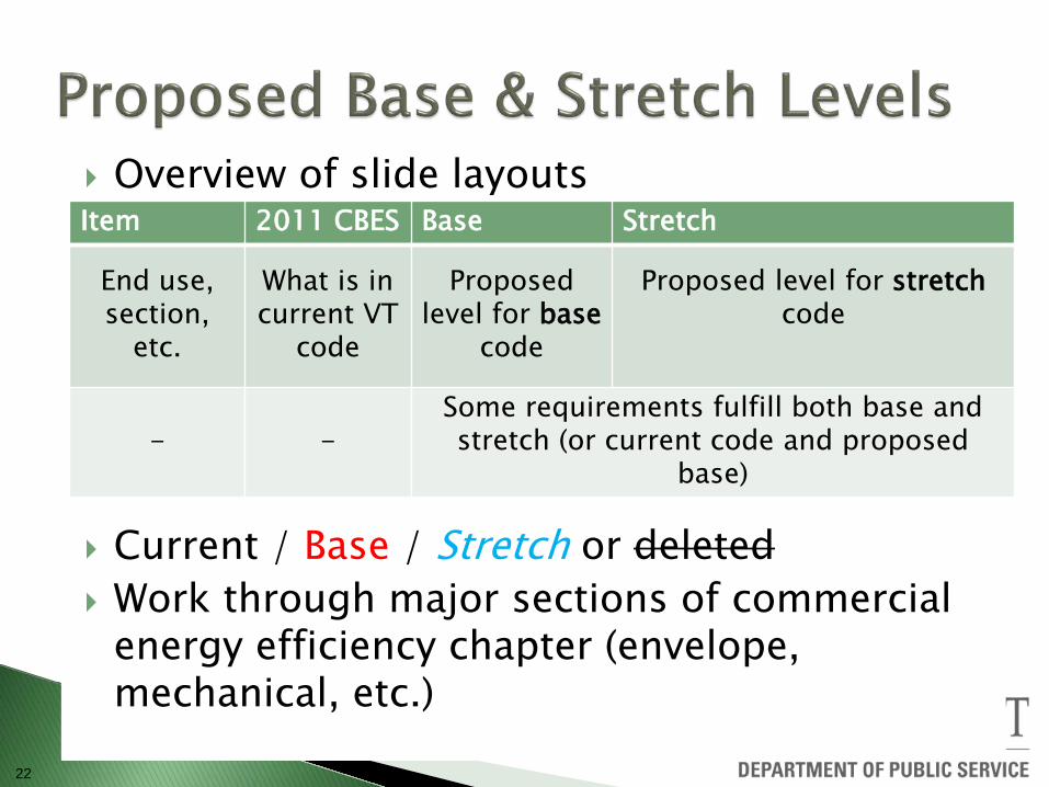
22
Overview of slide layouts
Current / Base / Stretch or deleted Work through major sections of commercial
energy efficiency chapter (envelope, mechanical, etc.)
Item 2011 CBES Base Stretch
End use, section,
etc.
What is in current VT
code
Proposed level for base
code
Proposed level for stretch code
- - Some requirements fulfill both base and stretch (or current code and proposed
base)

23
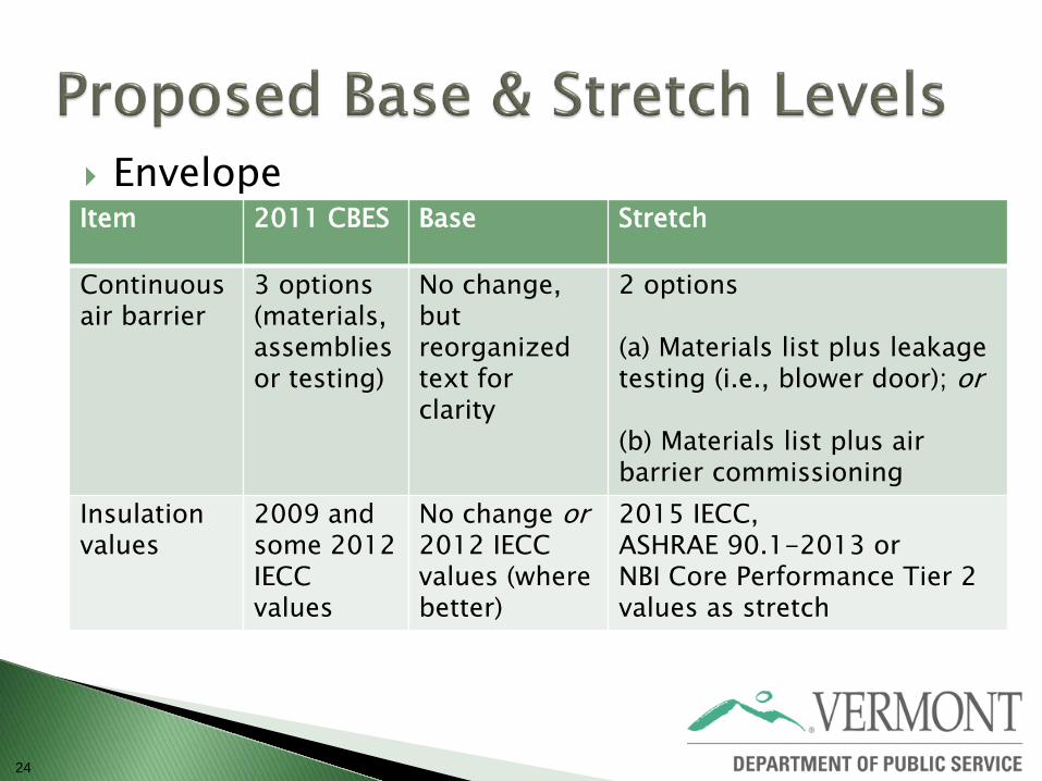
24
Envelope
Item 2011 CBES Base Stretch
Continuous air barrier
3 options (materials, assemblies or testing)
No change, but reorganized text for clarity
2 options (a) Materials list plus leakage testing (i.e., blower door); or (b) Materials list plus air barrier commissioning
Insulation values
2009 and some 2012 IECC values
No change or 2012 IECC values (where better)
2015 IECC, ASHRAE 90.1-2013 or NBI Core Performance Tier 2 values as stretch
25
Envelope – Base Code / Stretch Code
COMPONENT
MAXIMUM OVERALL U-FACTOR MINIMUM R-VALUES
All other Group R All other Group R Roofs Insulation entirely above
deck U-0.032 U-0.028
R-30ci R-35ci
Metal buildings U-0.049 U-0.031 U-0.029
See Assembly Descriptions R-25 + R-11 LS (Liner
System) R-30 + R-11 LS (Liner
System)
Attic and other U-0.027 U-0.021 U-0.017
R-38 R-49
~R-60
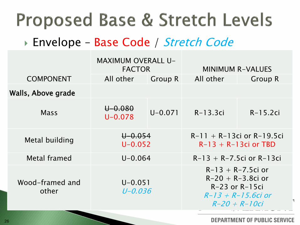
26
Envelope – Base Code / Stretch Code
COMPONENT
MAXIMUM OVERALL U-FACTOR MINIMUM R-VALUES
All other Group R All other Group R
Walls, Above grade
Mass U-0.080 U-0.078 U-0.071 R-13.3ci R-15.2ci
Metal building U-0.054 U-0.052
R-11 + R-13ci or R-19.5ci R-13 + R-13ci or TBD
Metal framed U-0.064 R-13 + R-7.5ci or R-13ci
Wood-framed and other
U-0.051 U-0.036
R-13 + R-7.5ci or R-20 + R-3.8ci or
R-23 or R-15ci R-13 + R-15.6ci or
R-20 + R-10ci
27
Envelope – Base Code / Stretch Code
COMPONENT
MAXIMUM OVERALL U-FACTOR MINIMUM R-VALUES
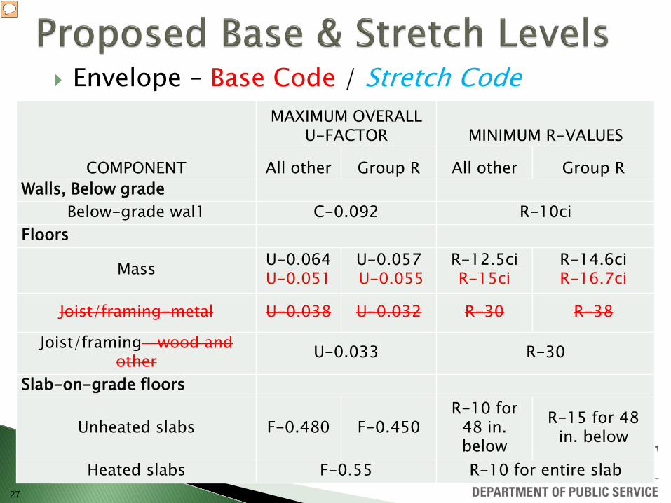
All other Group R All other Group R Walls, Below grade
Below-grade wal1 C-0.092 R-10ci Floors
Mass U-0.064 U-0.051
U-0.057 U-0.055
R-12.5ci R-15ci
R-14.6ci R-16.7ci
Joist/framing-metal U-0.038 U-0.032 R-30 R-38
Joist/framing—wood and other U-0.033 R-30
Slab-on-grade floors
Unheated slabs F-0.480 F-0.450 R-10 for
48 in. below
R-15 for 48 in. below
Heated slabs F-0.55 R-10 for entire slab
28
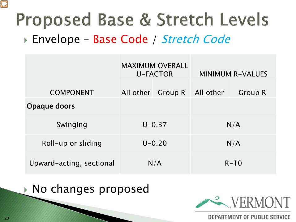
Envelope – Base Code / Stretch Code
No changes proposed
COMPONENT
MAXIMUM OVERALL U-FACTOR MINIMUM R-VALUES
All other Group R All other Group R
Opaque doors
Swinging U-0.37 N/A
Roll-up or sliding U-0.20 N/A
Upward-acting, sectional N/A R-10
29
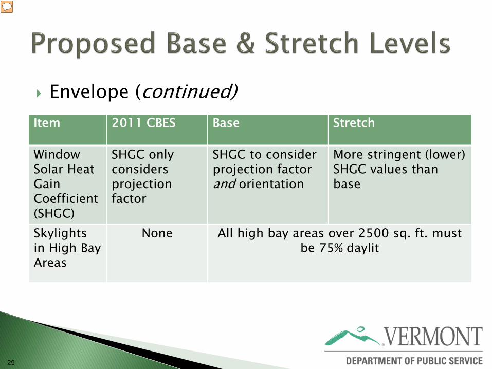
Envelope (continued)
Item 2011 CBES Base Stretch
Window Solar Heat Gain Coefficient (SHGC)
SHGC only considers projection factor
SHGC to consider projection factor and orientation
More stringent (lower) SHGC values than base
Skylights in High Bay Areas
None All high bay areas over 2500 sq. ft. must be 75% daylit
30
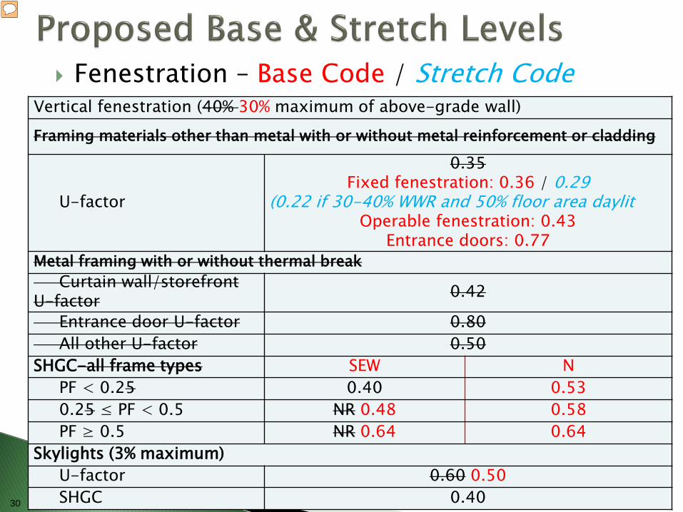
Fenestration – Base Code / Stretch Code
Vertical fenestration (40% 30% maximum of above-grade wall) Framing materials other than metal with or without metal reinforcement or cladding
U-factor
0.35 Fixed fenestration: 0.36 / 0.29
(0.22 if 30-40% WWR and 50% floor area daylit Operable fenestration: 0.43
Entrance doors: 0.77 Metal framing with or without thermal break Curtain wall/storefront U-factor 0.42
Entrance door U-factor 0.80 All other U-factor 0.50 SHGC-all frame types SEW N PF < 0.25 0.40 0.53 0.25 ≤ PF < 0.5 NR 0.48 0.58 PF ≥ 0.5 NR 0.64 0.64 Skylights (3% maximum) U-factor 0.60 0.50 SHGC 0.40
31
32
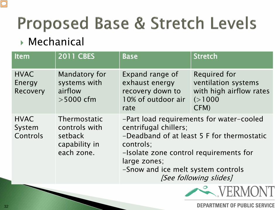
Mechanical
Item 2011 CBES Base Stretch
HVAC Energy Recovery
Mandatory for systems with airflow >5000 cfm
Expand range of exhaust energy recovery down to 10% of outdoor air rate
Required for ventilation systems with high airflow rates (>1000 CFM)
HVAC System Controls
Thermostatic controls with setback capability in each zone.
-Part load requirements for water-cooled centrifugal chillers; -Deadband of at least 5 F for thermostatic controls; -Isolate zone control requirements for large zones; -Snow and ice melt system controls
[See following slides]
33
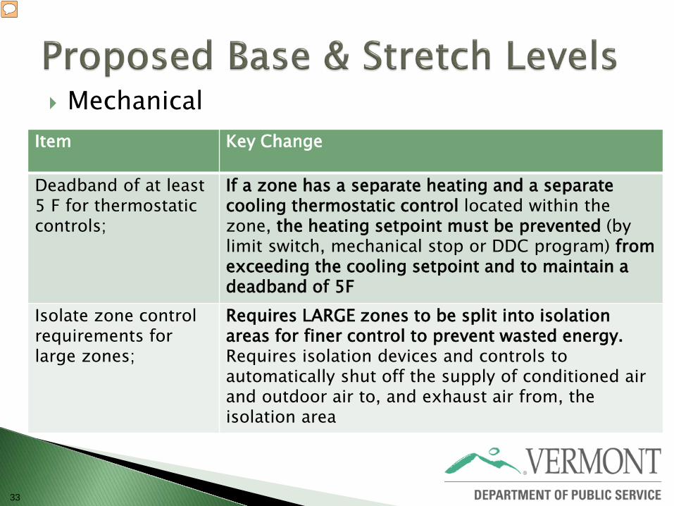
Mechanical
Item Key Change
Deadband of at least 5 F for thermostatic controls;
If a zone has a separate heating and a separate cooling thermostatic control located within the zone, the heating setpoint must be prevented (by limit switch, mechanical stop or DDC program) from exceeding the cooling setpoint and to maintain a deadband of 5F
Isolate zone control requirements for large zones;
Requires LARGE zones to be split into isolation areas for finer control to prevent wasted energy. Requires isolation devices and controls to automatically shut off the supply of conditioned air and outdoor air to, and exhaust air from, the isolation area
34
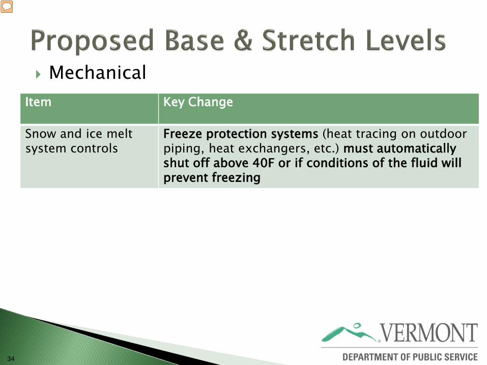
Mechanical
Item Key Change
Snow and ice melt system controls
Freeze protection systems (heat tracing on outdoor piping, heat exchangers, etc.) must automatically shut off above 40F or if conditions of the fluid will prevent freezing
35
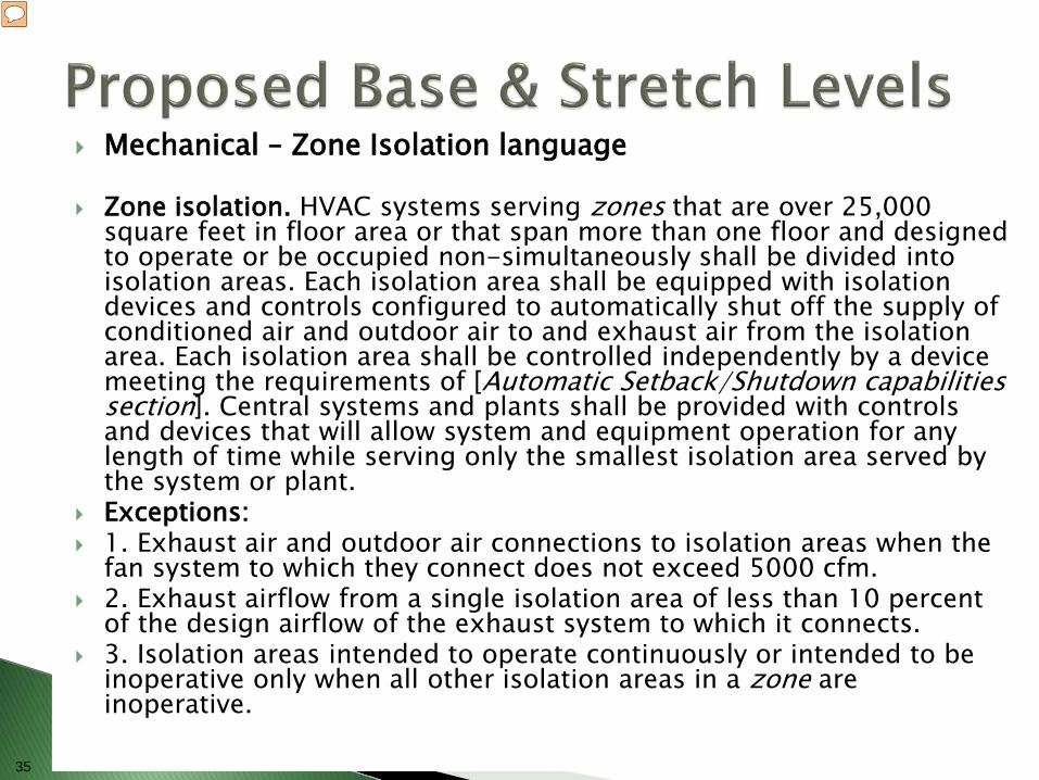
Mechanical – Zone Isolation language
Zone isolation. HVAC systems serving zones that are over 25,000 square feet in floor area or that span more than one floor and designed to operate or be occupied non-simultaneously shall be divided into isolation areas. Each isolation area shall be equipped with isolation devices and controls configured to automatically shut off the supply of conditioned air and outdoor air to and exhaust air from the isolation area. Each isolation area shall be controlled independently by a device meeting the requirements of [Automatic Setback/Shutdown capabilities section]. Central systems and plants shall be provided with controls and devices that will allow system and equipment operation for any length of time while serving only the smallest isolation area served by the system or plant.
Exceptions: 1. Exhaust air and outdoor air connections to isolation areas when the
fan system to which they connect does not exceed 5000 cfm. 2. Exhaust airflow from a single isolation area of less than 10 percent
of the design airflow of the exhaust system to which it connects. 3. Isolation areas intended to operate continuously or intended to be
inoperative only when all other isolation areas in a zone are inoperative.
36
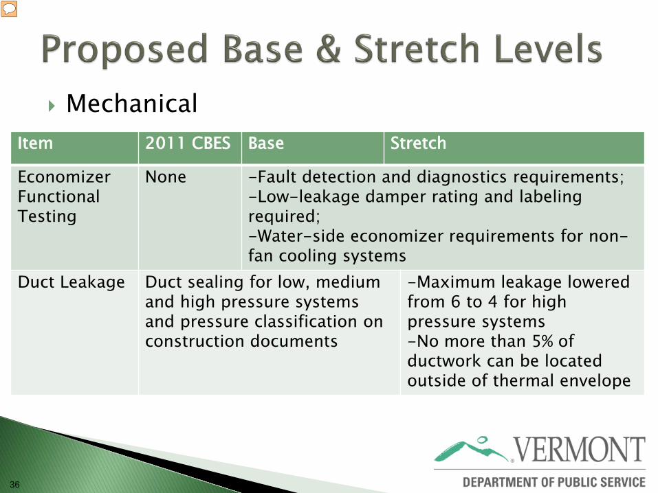
Mechanical
Item 2011 CBES Base Stretch
Economizer Functional Testing
None -Fault detection and diagnostics requirements; -Low-leakage damper rating and labeling required; -Water-side economizer requirements for non- fan cooling systems
Duct Leakage Duct sealing for low, medium and high pressure systems and pressure classification on construction documents
-Maximum leakage lowered from 6 to 4 for high pressure systems -No more than 5% of ductwork can be located outside of thermal envelope
37
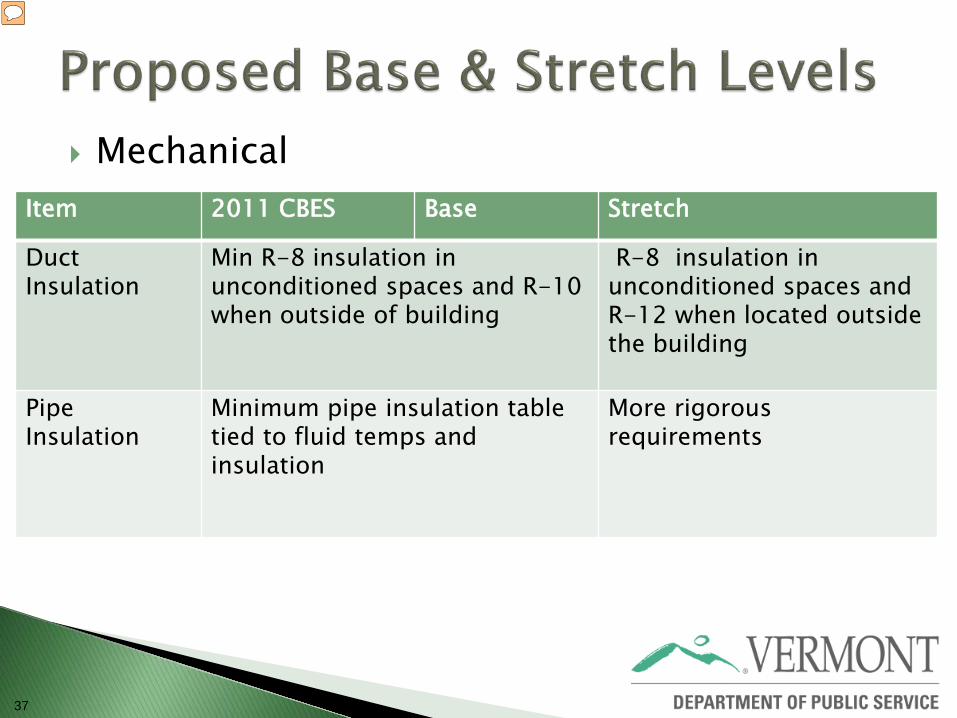
Mechanical
Item 2011 CBES Base Stretch
Duct Insulation
Min R-8 insulation in unconditioned spaces and R-10 when outside of building
R-8 insulation in unconditioned spaces and R-12 when located outside the building
Pipe Insulation
Minimum pipe insulation table tied to fluid temps and insulation
More rigorous requirements
38
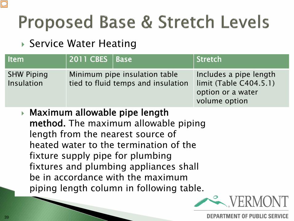
39
Service Water Heating
Maximum allowable pipe length method. The maximum allowable piping length from the nearest source of heated water to the termination of the fixture supply pipe for plumbing fixtures and plumbing appliances shall be in accordance with the maximum piping length column in following table.
Item 2011 CBES Base Stretch
SHW Piping Insulation
Minimum pipe insulation table tied to fluid temps and insulation
Includes a pipe length limit (Table C404.5.1) option or a water volume option
40
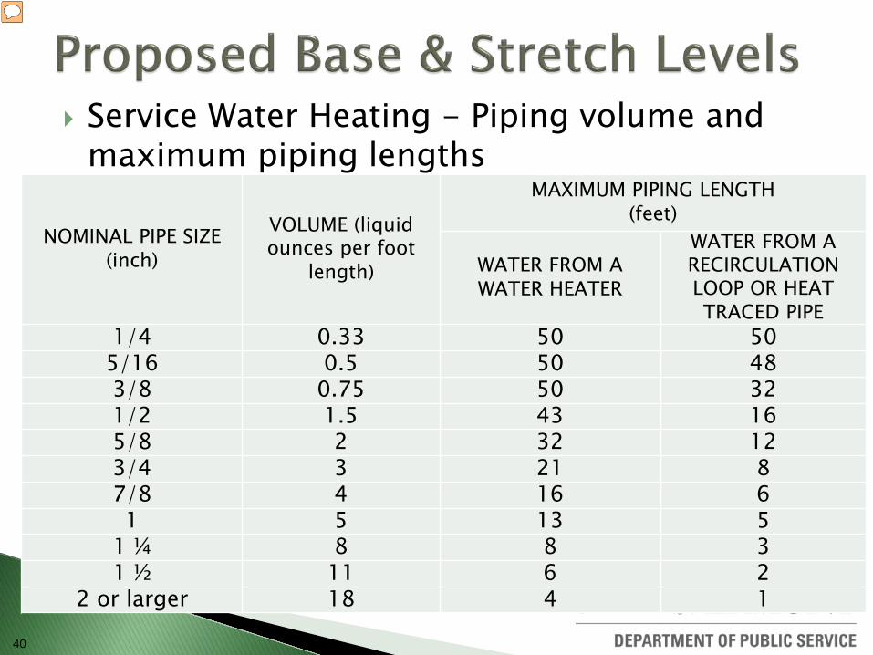
Service Water Heating - Piping volume and maximum piping lengths NOMINAL PIPE SIZE
(inch)
VOLUME (liquid ounces per foot
length)
MAXIMUM PIPING LENGTH (feet)
WATER FROM A WATER HEATER
WATER FROM A RECIRCULATION LOOP OR HEAT TRACED PIPE
1/4 0.33 50 50 5/16 0.5 50 48 3/8 0.75 50 32 1/2 1.5 43 16 5/8 2 32 12 3/4 3 21 8 7/8 4 16 6 1 5 13 5
1 ¼ 8 8 3 1 ½ 11 6 2
2 or larger 18 4 1
41
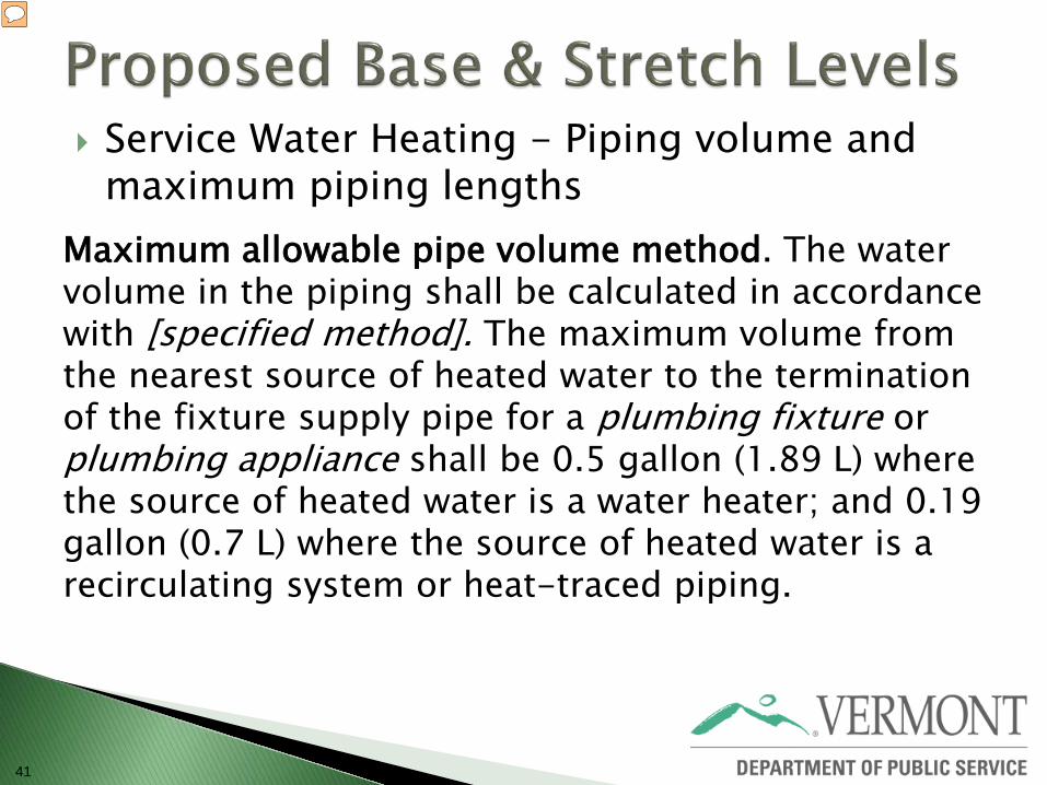
Service Water Heating - Piping volume and maximum piping lengths
Maximum allowable pipe volume method. The water volume in the piping shall be calculated in accordance with [specified method]. The maximum volume from the nearest source of heated water to the termination of the fixture supply pipe for a plumbing fixture or plumbing appliance shall be 0.5 gallon (1.89 L) where the source of heated water is a water heater; and 0.19 gallon (0.7 L) where the source of heated water is a recirculating system or heat-traced piping.
42
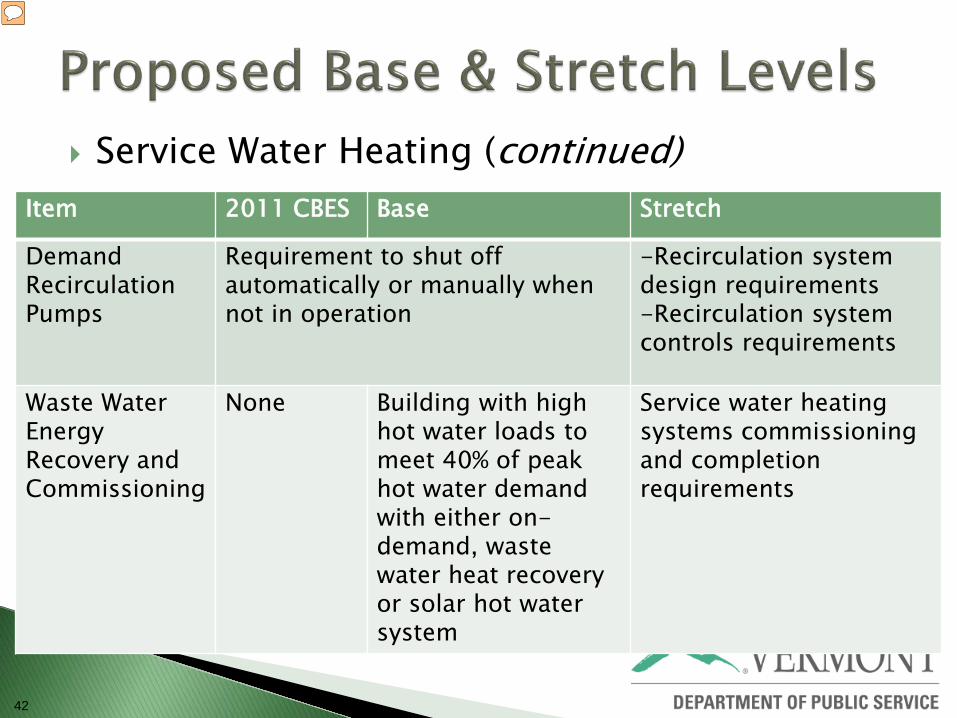
Service Water Heating (continued)
Item 2011 CBES Base Stretch
Demand Recirculation Pumps
Requirement to shut off automatically or manually when not in operation
-Recirculation system design requirements -Recirculation system controls requirements
Waste Water Energy Recovery and Commissioning
None Building with high hot water loads to meet 40% of peak hot water demand with either on-demand, waste water heat recovery or solar hot water system
Service water heating systems commissioning and completion requirements

43
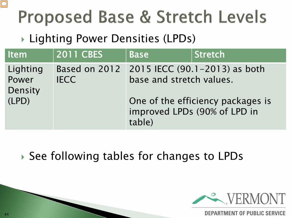
44
Lighting Power Densities (LPDs)
See following tables for changes to LPDs
Item 2011 CBES Base Stretch Lighting Power Density (LPD)
Based on 2012 IECC
2015 IECC (90.1-2013) as both base and stretch values. One of the efficiency packages is improved LPDs (90% of LPD in table)
45
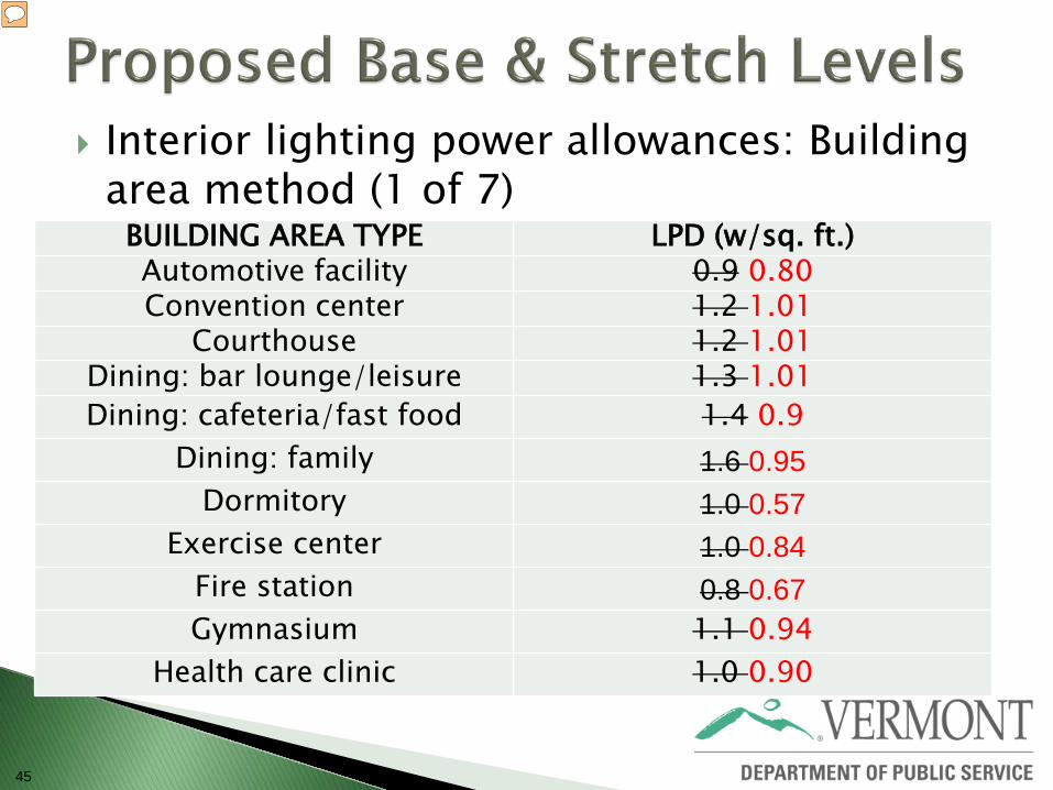
Interior lighting power allowances: Building area method (1 of 7)
BUILDING AREA TYPE LPD (w/sq. ft.) Automotive facility 0.9 0.80 Convention center 1.2 1.01
Courthouse 1.2 1.01 Dining: bar lounge/leisure 1.3 1.01 Dining: cafeteria/fast food 1.4 0.9
Dining: family 1.6 0.95 Dormitory 1.0 0.57
Exercise center 1.0 0.84 Fire station 0.8 0.67 Gymnasium 1.1 0.94
Health care clinic 1.0 0.90
46
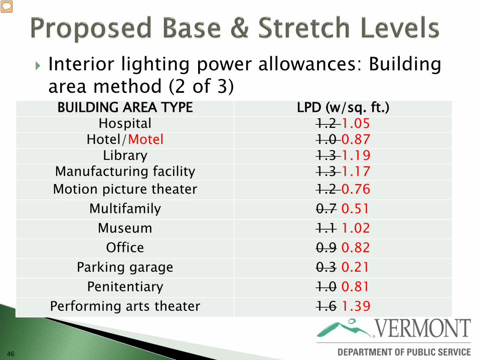
Interior lighting power allowances: Building area method (2 of 3)
BUILDING AREA TYPE LPD (w/sq. ft.) Hospital 1.2 1.05
Hotel/Motel 1.0 0.87 Library 1.3 1.19
Manufacturing facility 1.3 1.17 Motion picture theater 1.2 0.76
Multifamily 0.7 0.51 Museum 1.1 1.02 Office 0.9 0.82
Parking garage 0.3 0.21 Penitentiary 1.0 0.81
Performing arts theater 1.6 1.39
47
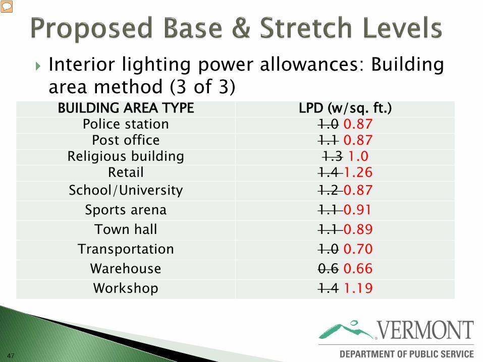
Interior lighting power allowances: Building area method (3 of 3)
BUILDING AREA TYPE LPD (w/sq. ft.) Police station 1.0 0.87
Post office 1.1 0.87 Religious building 1.3 1.0
Retail 1.4 1.26 School/University 1.2 0.87
Sports arena 1.1 0.91 Town hall 1.1 0.89
Transportation 1.0 0.70 Warehouse 0.6 0.66 Workshop 1.4 1.19
48
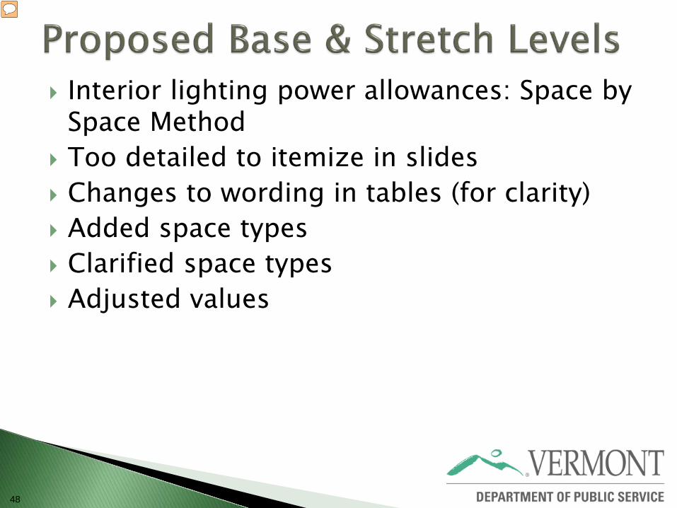
Interior lighting power allowances: Space by Space Method
Too detailed to itemize in slides Changes to wording in tables (for clarity) Added space types Clarified space types Adjusted values
49
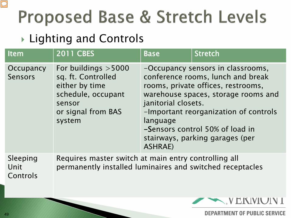
Lighting and Controls
Item 2011 CBES Base Stretch
Occupancy Sensors
For buildings >5000 sq. ft. Controlled either by time schedule, occupant sensor or signal from BAS system
-Occupancy sensors in classrooms, conference rooms, lunch and break rooms, private offices, restrooms, warehouse spaces, storage rooms and janitorial closets. -Important reorganization of controls language -Sensors control 50% of load in stairways, parking garages (per ASHRAE)
Sleeping Unit Controls
Requires master switch at main entry controlling all permanently installed luminaires and switched receptacles
50
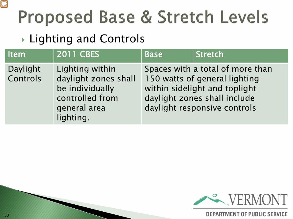
Lighting and Controls
Item 2011 CBES Base Stretch Daylight Controls
Lighting within daylight zones shall be individually controlled from general area lighting.
Spaces with a total of more than 150 watts of general lighting within sidelight and toplight daylight zones shall include daylight responsive controls
51
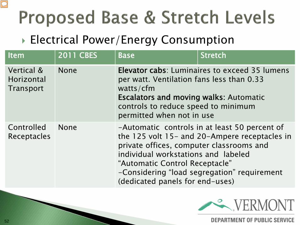
52
Electrical Power/Energy Consumption
Item 2011 CBES Base Stretch
Vertical & Horizontal Transport
None Elevator cabs: Luminaires to exceed 35 lumens per watt. Ventilation fans less than 0.33 watts/cfm Escalators and moving walks: Automatic controls to reduce speed to minimum permitted when not in use
Controlled Receptacles
None -Automatic controls in at least 50 percent of the 125 volt 15- and 20-Ampere receptacles in private offices, computer classrooms and individual workstations and labeled “Automatic Control Receptacle” -Considering “load segregation” requirement (dedicated panels for end-uses)
53
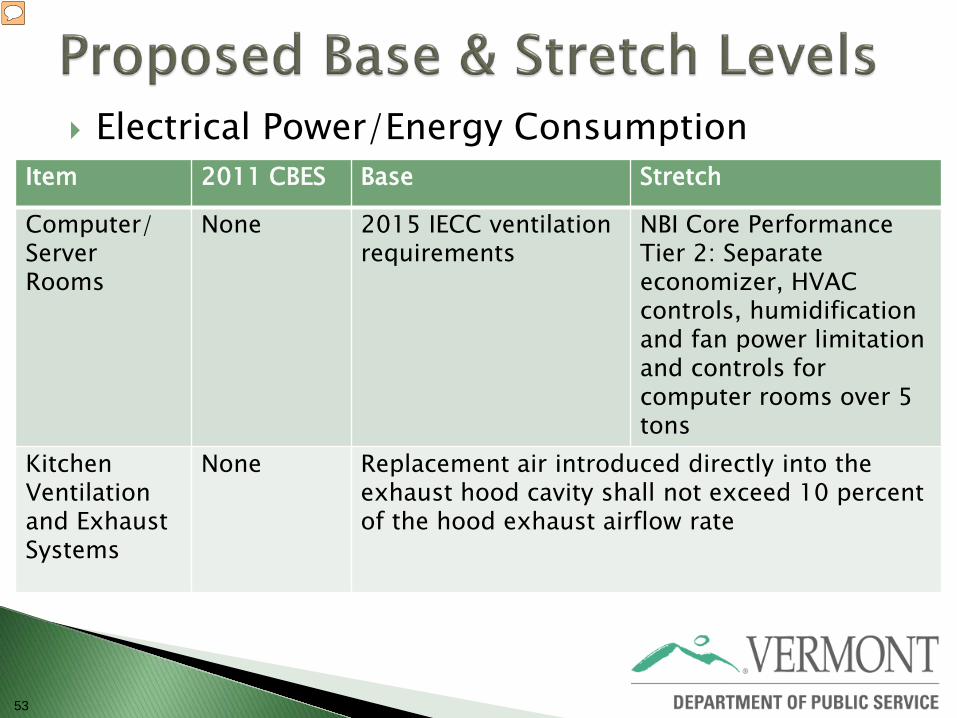
Electrical Power/Energy Consumption
Item 2011 CBES Base Stretch
Computer/ Server Rooms
None 2015 IECC ventilation requirements
NBI Core Performance Tier 2: Separate economizer, HVAC controls, humidification and fan power limitation and controls for computer rooms over 5 tons
Kitchen Ventilation and Exhaust Systems
None Replacement air introduced directly into the exhaust hood cavity shall not exceed 10 percent of the hood exhaust airflow rate
54
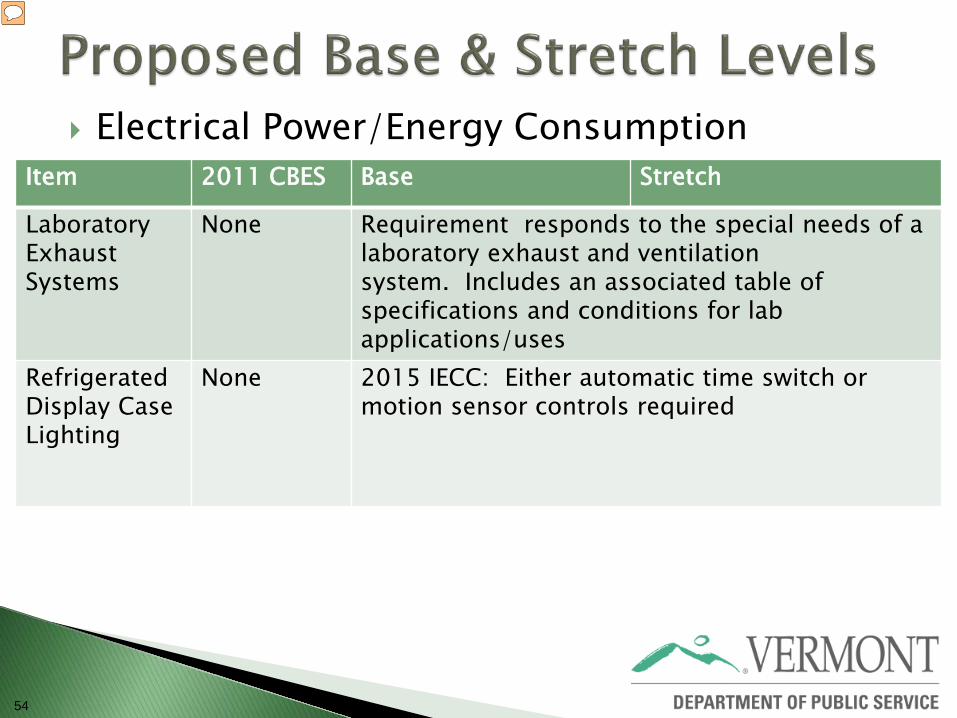
Electrical Power/Energy Consumption
Item 2011 CBES Base Stretch
Laboratory Exhaust Systems
None Requirement responds to the special needs of a laboratory exhaust and ventilation system. Includes an associated table of specifications and conditions for lab applications/uses
Refrigerated Display Case Lighting
None 2015 IECC: Either automatic time switch or motion sensor controls required

55
56
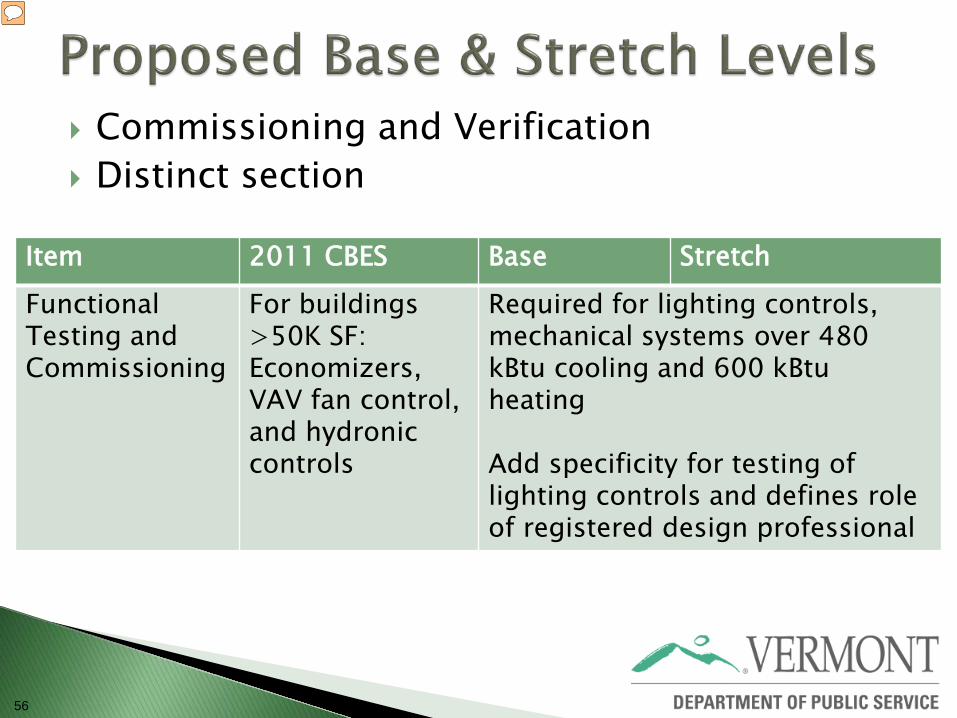
Commissioning and Verification Distinct section
Item 2011 CBES Base Stretch
Functional Testing and Commissioning
For buildings >50K SF: Economizers, VAV fan control, and hydronic controls
Required for lighting controls, mechanical systems over 480 kBtu cooling and 600 kBtu heating Add specificity for testing of lighting controls and defines role of registered design professional
57
58
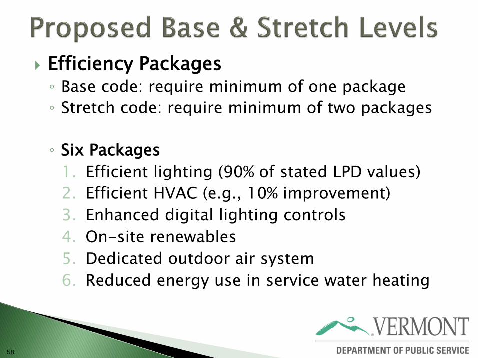
Efficiency Packages ◦ Base code: require minimum of one package ◦ Stretch code: require minimum of two packages
◦ Six Packages
1. Efficient lighting (90% of stated LPD values) 2. Efficient HVAC (e.g., 10% improvement) 3. Enhanced digital lighting controls 4. On-site renewables 5. Dedicated outdoor air system 6. Reduced energy use in service water heating
59
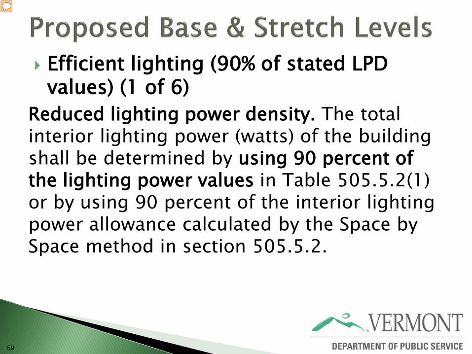
Efficient lighting (90% of stated LPD values) (1 of 6)
Reduced lighting power density. The total interior lighting power (watts) of the building shall be determined by using 90 percent of the lighting power values in Table 505.5.2(1) or by using 90 percent of the interior lighting power allowance calculated by the Space by Space method in section 505.5.2.
60
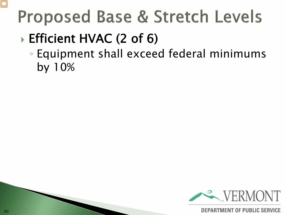
Efficient HVAC (2 of 6) ◦ Equipment shall exceed federal minimums
by 10%
61
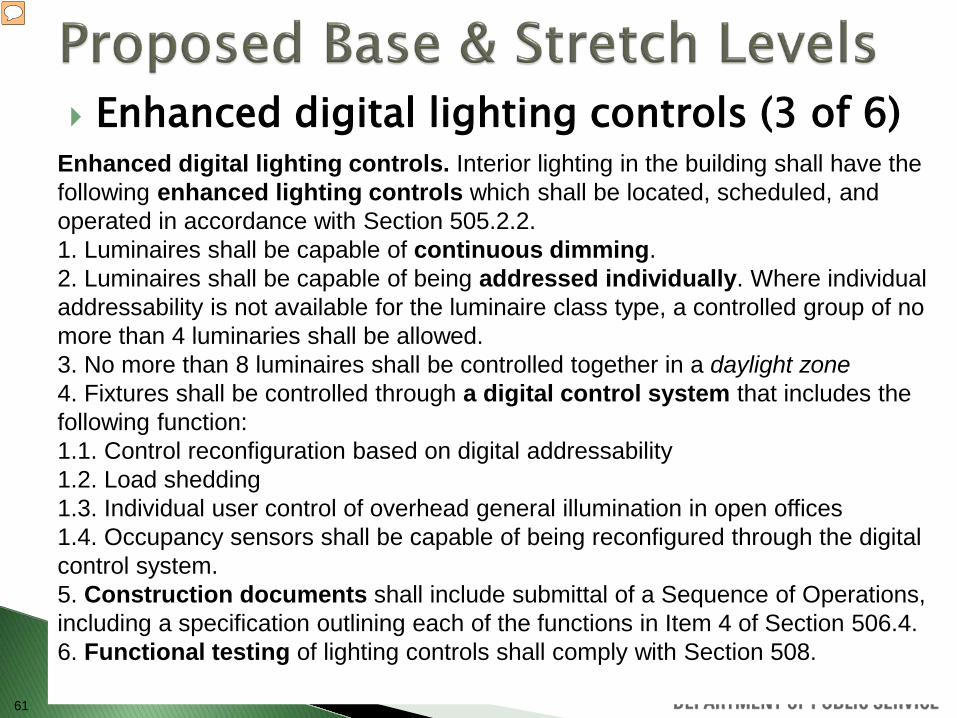
Enhanced digital lighting controls (3 of 6)
Enhanced digital lighting controls. Interior lighting in the building shall have the following enhanced lighting controls which shall be located, scheduled, and operated in accordance with Section 505.2.2. 1. Luminaires shall be capable of continuous dimming. 2. Luminaires shall be capable of being addressed individually. Where individual addressability is not available for the luminaire class type, a controlled group of no more than 4 luminaries shall be allowed. 3. No more than 8 luminaires shall be controlled together in a daylight zone 4. Fixtures shall be controlled through a digital control system that includes the following function: 1.1. Control reconfiguration based on digital addressability 1.2. Load shedding 1.3. Individual user control of overhead general illumination in open offices 1.4. Occupancy sensors shall be capable of being reconfigured through the digital control system. 5. Construction documents shall include submittal of a Sequence of Operations, including a specification outlining each of the functions in Item 4 of Section 506.4. 6. Functional testing of lighting controls shall comply with Section 508.
62
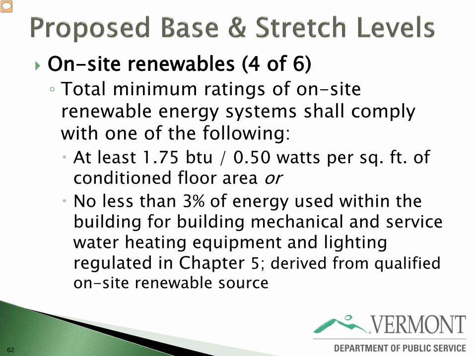
On-site renewables (4 of 6) ◦ Total minimum ratings of on-site
renewable energy systems shall comply with one of the following: At least 1.75 btu / 0.50 watts per sq. ft. of
conditioned floor area or No less than 3% of energy used within the
building for building mechanical and service water heating equipment and lighting regulated in Chapter 5; derived from qualified on-site renewable source
63
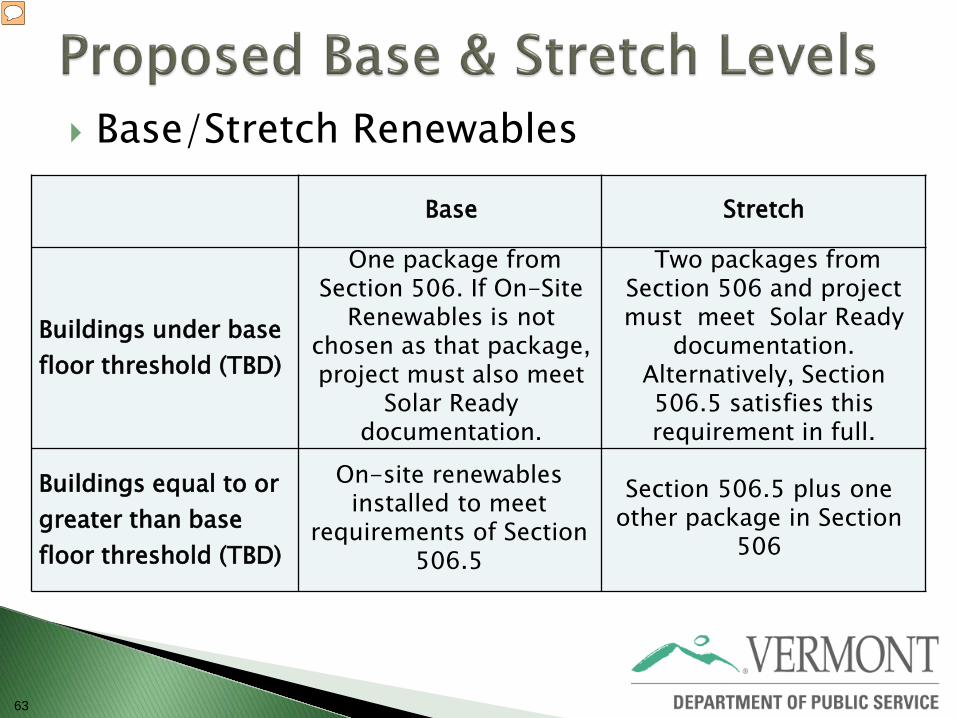
Base/Stretch Renewables
Base Stretch
Buildings under base floor threshold (TBD)
One package from Section 506. If On-Site
Renewables is not chosen as that package, project must also meet
Solar Ready documentation.
Two packages from Section 506 and project must meet Solar Ready
documentation. Alternatively, Section 506.5 satisfies this requirement in full.
Buildings equal to or greater than base floor threshold (TBD)
On-site renewables installed to meet
requirements of Section 506.5
Section 506.5 plus one other package in Section
506

64
Dedicated outdoor air system (5 of 6) ◦ Buildings covered by Section 503.4 [Complex HVAC
Systems]shall be equipped with an independent ventilation system designed to provide no less than the minimum 100 percent outdoor air to each individual occupied space as specified by the International Mechanical Code, to each individual occupied space. ◦ The ventilation system shall be capable of total
energy recovery. The HVAC system shall include supply-air temperature controls that automatically reset the supply-air temperature in response to representative building loads, or to outdoor air temperatures. ◦ The controls shall reset the supply air temperature
at least 25 percent of the difference between the design supply-air temperature and the design room air temperature.
65
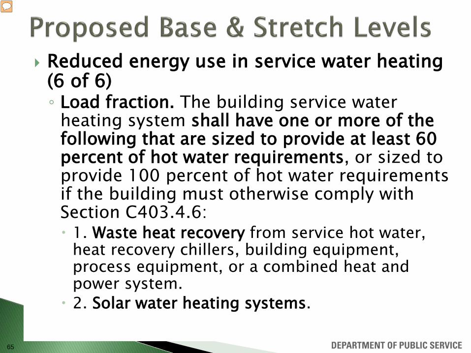
Reduced energy use in service water heating (6 of 6) ◦ Load fraction. The building service water
heating system shall have one or more of the following that are sized to provide at least 60 percent of hot water requirements, or sized to provide 100 percent of hot water requirements if the building must otherwise comply with Section C403.4.6: 1. Waste heat recovery from service hot water,
heat recovery chillers, building equipment, process equipment, or a combined heat and power system.
2. Solar water heating systems.

66
Q & A
67

Identify areas for further discussion
68
◦ Tim Guiterman, Navigant ◦ Stu Slote, Navigant ◦ Jim Edelson, New Buildings Institute
Follow up with:
Barry Murphy, Public Service Department 802-828-3183 [email protected]
http://publicservice.vermont.gov/topics/ energy_efficiency/code_update
69


![SIM Cohort 3 RFA Informational Webinar - 01-04-18 [Read-Only]resourcehub.practiceinnovationco.org/wp-content/... · SIM COHORT 3 RFA INFORMATIONAL WEBINAR DECEMBER 6TH 12:15PM - 1:15PM](https://static.documents.pub/doc/80x56/5f0b1b337e708231d42ee0ea/sim-cohort-3-rfa-informational-webinar-01-04-18-read-only-sim-cohort-3-rfa-informational.jpg)
![New Informational Resources for Addressing First Episode ... TA... · • Informational webinars ... Mobilizing Resources ... on the feedback survey that will follow this webinar!]](https://static.documents.pub/doc/80x56/5f9395f9ba4aac6f9a232fa8/new-informational-resources-for-addressing-first-episode-ta-a-informational.jpg)


