36
MODEL #: R1F, R2F & R4F-IR with IRC90H INFRARED FIRE DETECTION SYSTEM 1, 2 and 4 Channel Rack Mount Controller with IRC90H Detector Part Number: MAN-0024-00 Rev 3

MODEL #: R1F, R2F & R4F-IR with IRC90H
INFRARED FIRE DETECTION SYSTEM
1, 2 and 4 Channel Rack Mount Controllerwith IRC90H Detector
Part Number: MAN-0024-00 Rev 3

Copyright © 2002 Net Safety Monitoring Inc. Printed in Canada
This manual is provided for informational purposes only. Although the information contained in thismanual is believed to be accurate, it could include technical inaccuracies or typographical errors.Changes are, therefore, periodically made to the information within this document andincorporated without notice into subsequent revisions of the manual. Net Safety Monitoring Inc.assumes no responsibility for any errors that may be contained within this manual.
This manual is a guide for the use of a 1, 2 and 4 Channel Rack Mount Controller and the dataand procedures contained within this document have been verified and are believed to beadequate for the intended use of the controller. If the controller or procedures are used forpurposes other than as described in the manual without receiving prior confirmation of validity orsuitability, Net Safety Monitoring Inc. does not guarantee the results and assumes no obligation orliability.
No part of this manual may be copied, disseminated or distributed without the express writtenconsent of Net Safety Monitoring Inc.
Net Safety Monitoring Inc. products, are carefully designed and manufactured from high qualitycomponents and can be expected to provide many years of trouble free service. Each product isthoroughly tested, inspected and calibrated prior to shipment. Failures can occur which arebeyond the control of the manufacturer. Failures can be minimized by adhering to the operatingand maintenance instructions herein. Where the absolute greatest of reliability is required,redundancy should be designed into the system.
Net Safety Monitoring Inc., warrants its sensors and detectors against defective parts andworkmanship for a period of 24 months from date of purchase and other electronic assemblies for36 months from date of purchase.
No other warranties or liability, expressed or implied, will be honoured by Net Safety MonitoringINC
Contact Net Safety Monitoring Inc. or an authorized distributor for details.


Table of ContentsUnit I GENERAL INFORMATION . . . . . . . . . . . . . . . . . . . . . . . . . . . . . . . . . . . 1DESCRIPTION . . . . . . . . . . . . . . . . . . . . . . . . . . . . . . . . . . . . . . . . . . . . . . . . . . . . . . . . . . . . . . . . 1FEATURES . . . . . . . . . . . . . . . . . . . . . . . . . . . . . . . . . . . . . . . . . . . . . . . . . . . . . . . . . . . . . . . . . . 1CONTROLLER SPECIFICATIONS . . . . . . . . . . . . . . . . . . . . . . . . . . . . . . . . . . . . . . . . . . . . . . . . 1
Figure 1 - Controller Dimensions . . . . . . . . . . . . . . . . . . . . . . . . . . . . . . . . . . . . . . . . . . . . 2DETECTOR SPECIFICATIONS . . . . . . . . . . . . . . . . . . . . . . . . . . . . . . . . . . . . . . . . . . . . . . . . . . . 2
Figure 2a - Swivel Mount Dimension . . . . . . . . . . . . . . . . . . . . . . . . . . . . . . . . . . . . . . . . . 3Figure 2b - Detector Dimensions . . . . . . . . . . . . . . . . . . . . . . . . . . . . . . . . . . . . . . . . . . . . 3Figure 3 - Controller
Face-Plate . . . . . . . . . . . . . . . . . . . . . . . . . . . . . . . . . . . . . . . . . . . . . . . . . . . . . . 4BASIC OPERATION - CONTROLLER . . . . . . . . . . . . . . . . . . . . . . . . . . . . . . . . . . . . . . . . . . . . . . 4
CONTROLLER FACEPLATE DESCRIPTION . . . . . . . . . . . . . . . . . . . . . . . . . . . . . . . . . 4OUTPUTS . . . . . . . . . . . . . . . . . . . . . . . . . . . . . . . . . . . . . . . . . . . . . . . . . . . . . . . . . . . . . 4Table 1 - Selectable Output Options . . . . . . . . . . . . . . . . . . . . . . . . . . . . . . . . . . . . . . . . . 5Figure 4 - Jumper Selections for Isolated or Non-isolated Current Outputs . . . . . . . . . . . 5PROGRAMMING OPTIONS . . . . . . . . . . . . . . . . . . . . . . . . . . . . . . . . . . . . . . . . . . . . . . . 5EXTERNAL RESET . . . . . . . . . . . . . . . . . . . . . . . . . . . . . . . . . . . . . . . . . . . . . . . . . . . . . 6AUTOMATIC DIAGNOSTICS AND FAULT IDENTIFICATION . . . . . . . . . . . . . . . . . . . . . 6VOTING LOGIC (not applicable to R1F) . . . . . . . . . . . . . . . . . . . . . . . . . . . . . . . . . . . . . . 6
DETECTOR . . . . . . . . . . . . . . . . . . . . . . . . . . . . . . . . . . . . . . . . . . . . . . . . . . . . . . . . . . . . . . . . . . 6
Unit II IR FIRE DETECTION . . . . . . . . . . . . . . . . . . . . . . . . . . . . . . . . . . . . . . . 7SYSTEM APPLICATION . . . . . . . . . . . . . . . . . . . . . . . . . . . . . . . . . . . . . . . . . . . . . . . . . . . . . . . . 7DETECTOR SENSITIVITY . . . . . . . . . . . . . . . . . . . . . . . . . . . . . . . . . . . . . . . . . . . . . . . . . . . . . . . 7
SPECTRAL SENSITIVITY RANGE . . . . . . . . . . . . . . . . . . . . . . . . . . . . . . . . . . . . . . . . . 7CONE OF VISION . . . . . . . . . . . . . . . . . . . . . . . . . . . . . . . . . . . . . . . . . . . . . . . . . . . . . . . 8Figure 6 - Detector Cone of Vision . . . . . . . . . . . . . . . . . . . . . . . . . . . . . . . . . . . . . . . . . . 8
SYSTEM SENSITIVITY . . . . . . . . . . . . . . . . . . . . . . . . . . . . . . . . . . . . . . . . . . . . . . . . . . . . . . . . . 8
Unit III SYSTEM INSTALLATION . . . . . . . . . . . . . . . . . . . . . . . . . . . . . . . . . . . 8INSTALLATION . . . . . . . . . . . . . . . . . . . . . . . . . . . . . . . . . . . . . . . . . . . . . . . . . . . . . . . . . . . . . . . 8
GENERAL WIRING REQUIREMENTS . . . . . . . . . . . . . . . . . . . . . . . . . . . . . . . . . . . . . . . 8CONTROLLER WIRING . . . . . . . . . . . . . . . . . . . . . . . . . . . . . . . . . . . . . . . . . . . . . . . . . . 9Figure 7a - Wiring for R1F - IR with Non-Isolated Current Output . . . . . . . . . . . . . . . . . 10Figure 7b - Wiring for R1F - IR with Isolated Current Output . . . . . . . . . . . . . . . . . . . . . 11Figure 8a - Wiring for R2F - IR with Non-Isolated Current Output . . . . . . . . . . . . . . . . . 12Figure 8b - Wiring for R2F - IR with Isolated Current Output . . . . . . . . . . . . . . . . . . . . . 12Figure 9a - Wiring for R4F - IR with Non-Isolated Current Output . . . . . . . . . . . . . . . . . 13Figure 9b - Wiring for R4F - IR with Isolated Current Output . . . . . . . . . . . . . . . . . . . . . 14
POSITION AND DENSITY OF DETECTORS . . . . . . . . . . . . . . . . . . . . . . . . . . . . . . . . . . . . . . . 16MOUNTING THE DETECTOR . . . . . . . . . . . . . . . . . . . . . . . . . . . . . . . . . . . . . . . . . . . . 16Figure 10 - Detector with Swivel Mount Assembly . . . . . . . . . . . . . . . . . . . . . . . . . . . . . 16
DIP SWITCH SETTINGS . . . . . . . . . . . . . . . . . . . . . . . . . . . . . . . . . . . . . . . . . . . . . . . . . . . . . . . 16Figure 11a - Relay and Dip Switch Positions . . . . . . . . . . . . . . . . . . . . . . . . . . . . . . . . . 16Figure 11b - Dip Switch Operation . . . . . . . . . . . . . . . . . . . . . . . . . . . . . . . . . . . . . . . . . 16CHANNEL SELECTION . . . . . . . . . . . . . . . . . . . . . . . . . . . . . . . . . . . . . . . . . . . . . . . . . 17CONTROLLER SENSITIVITY ADJUSTMENT . . . . . . . . . . . . . . . . . . . . . . . . . . . . . . . . 17FIRE AREA VOTING SEQUENCE (not applicable to R1F) . . . . . . . . . . . . . . . . . . . . . . 18RELAY OUTPUTS LATCHING/NON-LATCHING . . . . . . . . . . . . . . . . . . . . . . . . . . . . . . 18RELAY OUTPUTS ENERGIZED/DE-ENERGIZED . . . . . . . . . . . . . . . . . . . . . . . . . . . . 18TIME DELAY FOR AREA ALARMS . . . . . . . . . . . . . . . . . . . . . . . . . . . . . . . . . . . . . . . . 19
RELAY SETTINGS . . . . . . . . . . . . . . . . . . . . . . . . . . . . . . . . . . . . . . . . . . . . . . . . . . . . . . . . . . . . 19Figure 11c - Relay Settings . . . . . . . . . . . . . . . . . . . . . . . . . . . . . . . . . . . . . . . . . . . . . . . 19
Unit IV SYSTEM OPERATION . . . . . . . . . . . . . . . . . . . . . . . . . . . . . . . . . . . . 19SYSTEM OPERATION . . . . . . . . . . . . . . . . . . . . . . . . . . . . . . . . . . . . . . . . . . . . . . . . . . . . . . . . 19

STARTUP PROCEDURE . . . . . . . . . . . . . . . . . . . . . . . . . . . . . . . . . . . . . . . . . . . . . . . 19CHECKOUT PROCEDURE . . . . . . . . . . . . . . . . . . . . . . . . . . . . . . . . . . . . . . . . . . . . . . 20MANUAL vi CHECK/COUNT TEST . . . . . . . . . . . . . . . . . . . . . . . . . . . . . . . . . . . . . . . . 20MANUAL CHECK PROCEDURE . . . . . . . . . . . . . . . . . . . . . . . . . . . . . . . . . . . . . . . . . . 21ALTERNATE TEST PROCEDURE . . . . . . . . . . . . . . . . . . . . . . . . . . . . . . . . . . . . . . . . 21
NORMAL OPERATION . . . . . . . . . . . . . . . . . . . . . . . . . . . . . . . . . . . . . . . . . . . . . . . . . . . . . . . . 21FIRE RESPONSE . . . . . . . . . . . . . . . . . . . . . . . . . . . . . . . . . . . . . . . . . . . . . . . . . . . . . 21Table 2 - Current Outputs . . . . . . . . . . . . . . . . . . . . . . . . . . . . . . . . . . . . . . . . . . . . . . . . 22AUTOMATIC DIAGNOSTICS AND FAULT IDENTIFICATION . . . . . . . . . . . . . . . . . . . 22Table 3 - Error Codes . . . . . . . . . . . . . . . . . . . . . . . . . . . . . . . . . . . . . . . . . . . . . . . . . . . 23
MAIN MENU . . . . . . . . . . . . . . . . . . . . . . . . . . . . . . . . . . . . . . . . . . . . . . . . . . . . . . . . . . . . . . . . 23ERROR CHECK MODE (Err Chc) . . . . . . . . . . . . . . . . . . . . . . . . . . . . . . . . . . . . . . . . . 24BYPASS MODE (bPS) . . . . . . . . . . . . . . . . . . . . . . . . . . . . . . . . . . . . . . . . . . . . . . . . . . 24
SPECIAL FUNCTION MENU . . . . . . . . . . . . . . . . . . . . . . . . . . . . . . . . . . . . . . . . . . . . . . . . . . . 24FORCED CURRENT OUTPUT MODE (FoP) . . . . . . . . . . . . . . . . . . . . . . . . . . . . . . . . 24CURRENT CALIBRATION MODE (CuC) . . . . . . . . . . . . . . . . . . . . . . . . . . . . . . . . . . . 25ADDRESS SET MODE (do not use) . . . . . . . . . . . . . . . . . . . . . . . . . . . . . . . . . . . . . . . 25
Unit V MAINTENANCE . . . . . . . . . . . . . . . . . . . . . . . . . . . . . . . . . . . . . . . . . . 25ROUTINE MAINTENANCE . . . . . . . . . . . . . . . . . . . . . . . . . . . . . . . . . . . . . . . . . . . . . . . . . . . . . 25TROUBLESHOOTING . . . . . . . . . . . . . . . . . . . . . . . . . . . . . . . . . . . . . . . . . . . . . . . . . . . . . . . . 26DEVICE REPAIR AND RETURN . . . . . . . . . . . . . . . . . . . . . . . . . . . . . . . . . . . . . . . . . . . . . . . . 26
Appendix A Net Safety Monitoring Inc. Electrostatic Sensitive DeviceHandling Procedure . . . . . . . . . . . . . . . . . . . . . . . . . . . . . . . . . . . . . . . . . . . . 27
Appendix B Record Of Dip Switch Settings . . . . . . . . . . . . . . . . . . . . . . . . 28
Appendix C Wire Resistance In Ohms . . . . . . . . . . . . . . . . . . . . . . . . . . . . . 29

- 1 -
Unit I GENERAL INFORMATIONDESCRIPTIONThe IRC90H Flame Detector combined with the R1F, R2F or R4F-IR fire controller provide fast,reliable flame detection in a wide variety of applications. The microprocessor based controllerssimultaneously monitor up to four infrared (IR) detectors to provide maximum operating flexibilityat minimum expense. The Automatic Visual Integrity (vi) feature provides a continuous check ofoptical surfaces, sensitivity and electronic circuitry of the detector. Automatic fault identificationmonitors system operation and provides a digital display of system status using a numerical code.Controller response includes actuation of relays for direct control of field response devices and afull array of faceplate indicators. Other features include individual channel and area identification,"voting" capability and manual vi testing.
FEATURES< Instantaneous response to infrared radiation< Automatic and manual visual integrity (vi) testing< Adjustable sensitivity and time delay< All automatic test functions performed with the system on line< Automatic fault identification< Individual channel identification with voting options< Latching area LEDs identify the area responding to fire< Micro-processor based controller is easily field-programmable< Two digital displays, one bar graph display and high intensity LEDs indicate
system status information< Relay outputs are field adjustable as latching or non-latching< Alarm relays are programmable for normally energized or de-energized operation< Individual detector output (count rate) can be visually monitored on the digital
display< Two 4-20mA current outputs (R2F and R4F). One 4-20mA output on R1F< Conduit seals recommended to prevent moisture damage but not required
CONTROLLER SPECIFICATIONS< Operating Voltage:
24Vdc nominal. 18 to 32Vdc.
< Power Consumption (controller only):2.4 Watts nominal, 4.4 Watts maximum 100 mA nominal, 180 mA maximum at 24 Volts DC
Maximum startup current is 1.5 Amperes for 10 milliseconds. Power supplies withfold back current limiting are not recommended.
< Maximum Ripple:Ripple should not exceed 5 Volts peak-to-peak. The sum of DC plus ripple mustbe $18 Vdc and #32 Vdc
< Temperature Range:Operating: -40ºC to +85ºC (-40ºF to +185ºF)Storage: -55ºC to +150ºC (-65ºF to +302ºF)

- 2 -
< Relay Contacts:Normally open/normally closed contacts rated for 5 Amperes at 30 Volts DC/ 250Volts AC
< Current Outputs:4-20mA DC into a maximum external loop resistance of 600 Ohms at 18-32 VoltsDC
< Dimensions:Refer to Figure 1
< Shipping Weight (approximate):2 lbs (0.9 kilograms)
< Certification:CSA certified for ordinary, non-hazardous general purpose locations
< System Sensitivity:Sensitivity for the standard controller is field adjustable over a range of 2 through30 unit counts in increments of 2 units. The maximum response distance isachieved at a 2 unit sensitivity setting. For applications involving high backgroundradiation potential, the system can be de-sensitized by increasing the count raterequired to actuate alarms. The 30 unit setting is the lowest sensitivity.
< Response Time:Response to a saturating (high intensity) IR source is typically 10 milliseconds forthe instant alarm outputs and 0.5 seconds for the area alarm outputs whensensitivity is set for 2 units and time delay is set for 0.5 seconds (minimumsettings)
Figure 1 - Controller Dimensions
DETECTOR SPECIFICATIONS< Operating Voltage:
24Vdc ± 3V

- 3 -
Figure 2b - Detector Dimensions
0.5"
5.50
"
0.25"
2.50"
4.13
"
4, 1/4" holes in base for mounting
Figure 2a - Swivel Mount Dimension
< Power Consumption (each detector):1.45 Watts nominal, 2.9 Watts maximum60mA nominal, 120mA maximum
< Temperature Range:Operating: -40ºC to +125ºC (-40ºF to +257ºF)Storage: -55ºC to +150ºC (-65ºF to +302ºF)
< Dimensions:Refer to Figures 2a and 2b
< Detector Enclosure Materials:Available in anodized copper-free aluminum or optional stainless steel
< Shipping Weight (approximate):2 lbs (0.9 kilograms)
< Certification:CSA, NRTL/C, NEMA 4X certified for hazardous locationsClass 1, Division 1, Groups B, C and DIEC approval (Class 1, Zone 1 Groups IIB+H2 T5)
< Spectral Sensitivity Range:The detector responds to IR radiation in the 4.4 micrometre range
< Cone of Vision:The detector has a nominal 90 degree cone of vision

- 4 -
Figure 3 - ControllerFace-Plate
BASIC OPERATION - CONTROLLERCONTROLLER FACEPLATE DESCRIPTION
The controller faceplate provides LEDs and two digital displays foridentifying status conditions, a bar graph display for indicating an alarmcondition and MENU/SET and SELECT/RESET push-button switches fortesting and resetting the system. Refer to Figure 3.
< Digital Displays - The upper digital display is normally off.If a fire alarm or visual integrity fault is detected, it indicatesthe channel number of the alarm or fault. The digitaldisplays indicate system status including system errorcodes, visual integrity (vi) faults, system faults or firealarms. The lower display shows ‘nor’ in normal operatingmode. If more than one channel is in an alarm or faultcondition the digital displays will cycle through thesechannels. Since at least one display is always lit they alsofunction as a power indicator.
< Bar Graph Display - Normally off. Flashing when firedetected in any area.
< INSTANT LED - (no time delay) Flashes when anydetector signal exceeds the fire sensitivity setting.
< AREA 1 & 2 LEDs - (Area 1 only for R1F) If the selected“voting” criteria of the area and the preset time delay haselapsed the corresponding LED starts flashing.
< FAULT LED - Flashes upon detection of an overall systemfault or vi fault.
< CHANNEL LEDs - (1, 2, 3 or 4 depending on model) Flash to indicate detector inalarm and remain illuminated until reset, after an alarm condition has returned tonormal.
< MENU/SET Push-button - is used to enter the main menu, to toggle throughmenu selections and in conjunction with the SELECT/RESET push-button toenter the special functions menu.
< SELECT/RESET Push-button - is used for a basic system reset, menu selectionand with the MENU/SET push-button to enter the special functions menu. Thisswitch is also used during the manual vi test.
OUTPUTS
Relay Outputs:
The instant, area and fault relays have SPDT contacts rated 5A at 30 Volts dc or 250 Volts ac.
The instant and area alarm relays are programmable for either normally energized or normally de-energized operation and for latching or non-latching (programmable as a group not individually).The fault relay is only normally energized. The relays can be configured with jumpers for normallyopen or normally closed contacts.

- 5 -
RECOMMENDATION
The fault relay output should not be used to activate an automatic shutdown procedure.The fault output indicates a potential problem with the controller, not an alarm condition.
Refer to Table 1 for a summary of the relay programming options.
Table 1 - Selectable Output Options
OUTPUTSelectable Normally
Open/ClosedSelectable Normally
Energized/De-EnergizedSelectable
Latching/Non-Latching
AREA1 Y Y Y
INSTANT Y Y Y
FAULT Y N2 N3
1 Area alarms are programmed together, not individually2 Fault relay is no rmally energized3 Fault relay is non-latching
Current Outputs:4-20 mA DC current outputs transmit system information to other devices. The current outputs canbe wired for isolated or non-isolated operation by changing the jumpers as shown in Figure 4.Refer to Unit IV, System Operation for a description of the current output signal levels.
Figure 4 - Jumper Selections for Isolated or Non-isolated Current Outputs
PROGRAMMING OPTIONS
DIP switches located on the circuit board are used to “program” various options including:< channel selection< system sensitivity< fire area voting logic< time delay for fire area alarms

- 6 -
< relay latching/non-latching selection< relay energized/de-energized selection
NOTE:Power to the controller must be cycled OFF-ON to make dip switch changes takeeffect.
EXTERNAL RESET
A normally open, momentary closure switch connected between the external reset terminal andthe negative power terminal provides remote reset.
AUTOMATIC DIAGNOSTICS AND FAULT IDENTIFICATION
The micro-processor based controller features self-testing circuitry that continuously checks forproblems that could prevent proper system response. When power is applied, the micro-processorautomatically tests memory. In the normal operating mode it continuously monitors the system toensure proper functioning. A "watchdog" timer is maintained to ensure that the program is runningcorrectly.
The main loop of the operating program continuously cycles through the automatic visual integrity(vi) test, checking each detector and its wiring. The micro-processor can be interrupted by anyone of several status changes such as a fault or a "fire" signal from one of the detection areas totake appropriate action.
If a system or vi fault is detected the fault LED flashes, digital displays and current outputs identifythe nature of the fault and the fault relay is de-energized.
VOTING LOGIC (not applicable to R1F)
The controller can be DIP switch configured for either one or two monitoring areas. For a one areaconfiguration, all channels are considered as being in Area 1 and both area alarm relays will beactivated together.
The dip switches can be set so that only one channel need be in alarm to activate the area alarmor that any two channels must ‘vote’ (see a fire at the same time) to activate the area alarm. Theinstant alarm will be activated when any channel sees IR radiation exceeding the preset sensitivitysetting, no matter what voting option is being used.
For a two area configuration, channel one (one and two for R4F) make up Area 1 and channel two(three and four for R4F) make up Area 2. With the R4F, each area alarm may be programmedwith different voting criteria (ie. Area 1 may be set so that either channel one OR channel two mayactivate the area alarm, and Area 2 may be set so that both channels three AND four must seethe fire at the same time to activate the area alarm).
DETECTORThe detector responds to IR radiation in the 4.4 micrometre range. It is insensitive to direct orreflected sunlight, arc welding, lightning and other ultraviolet producing phenomena.
The detector is housed in an explosion-proof enclosure that is designed to meet most national andinternational standards. It is available in anodized aluminum or optional stainless steel.
The detector is typically mounted with a swivel mounting assembly which is recommended. Othermounting arrangements are possible.

- 7 -
Unit II IR FIRE DETECTIONSYSTEM APPLICATIONThe detector responds instantly to infrared radiation emitted by a flame. It is designed for use inhazardous locations and is suitable for use in outdoor applications.
Typical applications for IR detection systems are:
< around highly combustible materials< if instantaneous response to flame is needed< where automated fire protection is required< to protect large capital investments
Petroleum Products Handling< petroleum loading terminals< offshore platforms< pipeline stations< tank farms< refineries< engine rooms
Gaseous Fuel Handling< butane and propane loading and storage< pipeline compressor stations< gas gathering facilities< LNG loading, transfer and storage < gas turbines
Other Processes< paint spray booths< chemical and petrochemical production< powder coating booths
Automated fire protection systems also have applications in any manufacturing or research facilitywhere the potential of fire may be low to moderate but the losses due to a fire would be high.
DETECTOR SENSITIVITYSPECTRAL SENSITIVITY RANGE
The IR fire detector responds to a radiation wavelength of 4.4 micrometre. It is not normallysensitive to arc welding, lightning or other ultraviolet sources.
NOTE:Infrared detectors are sensitive to black body heat sources and if this type of radiation canbe expected, nuisance alarms must be controlled through proper application includingcareful positioning and shielding of the detectors. Some applications may require a UV/IRsystem.

- 8 -
CONE OF VISION
The fire detector has a nominal 90 degree cone of vision. Figure 6 shows the cone of vision anddetector response to a IR source at various distances. The practical application distance is up toabout 50 feet (15 metres). The distance is directly related to the intensity of the infrared radiationsource.
Figure 6 - Detector Cone of Vision
SYSTEM SENSITIVITYThe IR tube response to different fires at the same distance is unpredictable. Generally, if a firedoubles in size the tube response is increased by about 60 percent.
Controller sensitivity and time delay settings for various applications is dependent on the severityof the hazard and the action required if a fire occurs. The system can be adjusted to varioussensitivity levels by programming the controller to respond at a pre-determined detector count ratewhich is dependent upon the intensity of the infrared radiation reaching the detector, which in turndepends on the type of fuel, temperature, flame size, distance from the detector and concentrationof IR absorbing vapors present.
Programming the controller to respond to a low count rate results in high system sensitivity.
Unit III SYSTEM INSTALLATIONINSTALLATIONGENERAL WIRING REQUIREMENTS
NOTE:The wiring procedures in this manual are intended to ensure proper functioning of thedevice under normal conditions. However, because of the many variations in wiring codesand regulations, total compliance to these ordinances cannot be guaranteed. Be certainthat all wiring complies with applicable regulations that relate to the installation ofelectrical equipment in a hazardous area. If in doubt, consult a qualified official beforewiring the system.
- 9 -
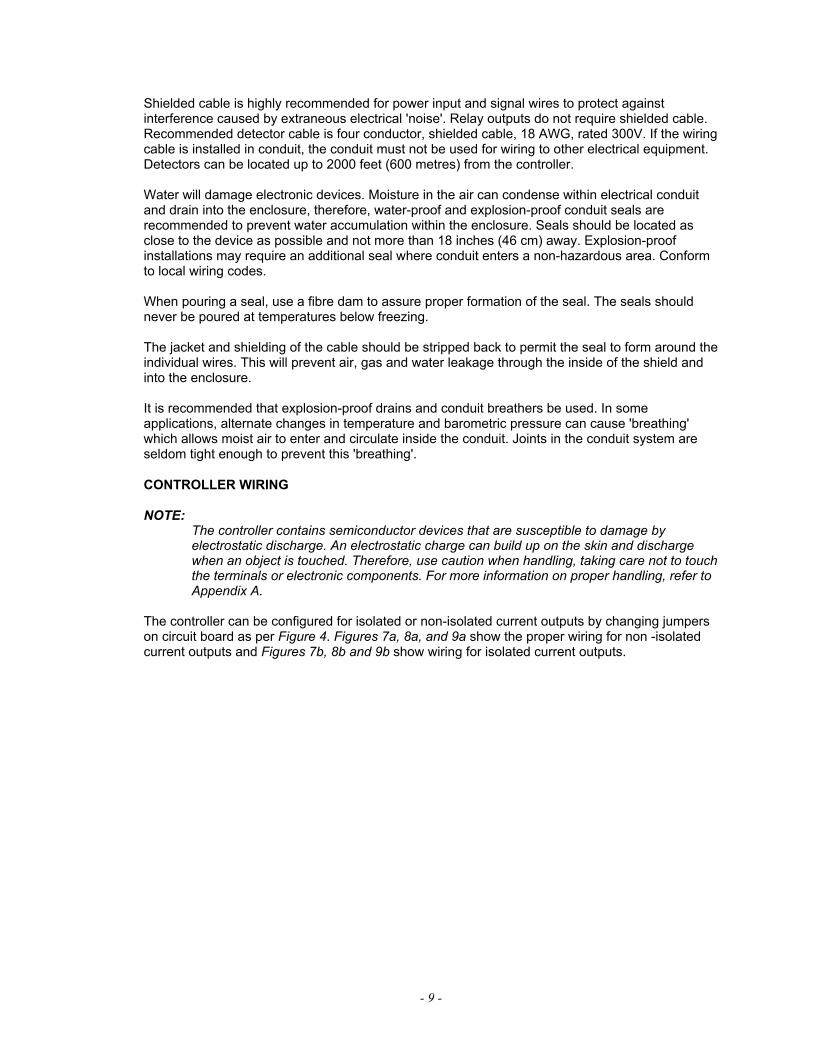
Shielded cable is highly recommended for power input and signal wires to protect againstinterference caused by extraneous electrical 'noise'. Relay outputs do not require shielded cable.Recommended detector cable is four conductor, shielded cable, 18 AWG, rated 300V. If the wiringcable is installed in conduit, the conduit must not be used for wiring to other electrical equipment.Detectors can be located up to 2000 feet (600 metres) from the controller.
Water will damage electronic devices. Moisture in the air can condense within electrical conduitand drain into the enclosure, therefore, water-proof and explosion-proof conduit seals arerecommended to prevent water accumulation within the enclosure. Seals should be located asclose to the device as possible and not more than 18 inches (46 cm) away. Explosion-proofinstallations may require an additional seal where conduit enters a non-hazardous area. Conformto local wiring codes.
When pouring a seal, use a fibre dam to assure proper formation of the seal. The seals shouldnever be poured at temperatures below freezing.
The jacket and shielding of the cable should be stripped back to permit the seal to form around theindividual wires. This will prevent air, gas and water leakage through the inside of the shield andinto the enclosure.
It is recommended that explosion-proof drains and conduit breathers be used. In someapplications, alternate changes in temperature and barometric pressure can cause 'breathing'which allows moist air to enter and circulate inside the conduit. Joints in the conduit system areseldom tight enough to prevent this 'breathing'.
CONTROLLER WIRING
NOTE:The controller contains semiconductor devices that are susceptible to damage byelectrostatic discharge. An electrostatic charge can build up on the skin and dischargewhen an object is touched. Therefore, use caution when handling, taking care not to touchthe terminals or electronic components. For more information on proper handling, refer toAppendix A.
The controller can be configured for isolated or non-isolated current outputs by changing jumperson circuit board as per Figure 4. Figures 7a, 8a, and 9a show the proper wiring for non -isolatedcurrent outputs and Figures 7b, 8b and 9b show wiring for isolated current outputs.

- 10 -
Figure 7a - Wiring for R1F - IR with Non-Isolated Current Output

- 11 -
Figure 7b - Wiring for R1F - IR with Isolated Current Output
- 12 -
Figure 8a - Wiring for R2F - IR with Non-Isolated Current Output

- 13 -
Figure 8b - Wiring for R2F - IR with Isolated Current Output

- 14 -
Figure 9a - Wiring for R4F - IR with Non-Isolated Current Output

- 15 -
Figure 9b - Wiring for R4F - IR with Isolated Current Output

- 16 -
Figure 10 - Detector with Swivel Mount Assembly
POSITION AND DENSITY OF DETECTORSThe detector has a nominal 90º cone of vision. In an application such as a loading rack with aceiling height of 25 feet (7.5 metres) where it is desired to have complete detector coverage atfloor level and a detector is mounted 2 feet (0.6 metre) from the ceiling and pointed straight down,the distance from the detector to the designated level would be 23 feet (7 metres) and because ofits 90º cone of vision the detector would cover a circular area 46 feet (14 metres) in diameter atfloor level. A sketch of the area to be covered will indicate the number of detectors required tomonitor the area. Detectors should be placed as close as practical to the expected fire hazard.
MOUNTING THE DETECTOR
Locate detectors to ensure an unobstructed view of the area to be monitored and whereaccessible for cleaning the detector window and vi reflecting surface. Take care so dirt and dustwill not accumulate and obscure the detector viewing window. To minimize dirt accumulationaround the vi surfaces, mount the detectors so that the internal vi tube is on top. The silverexternal reflector should be placed directly over the vi tube. Refer to Figures 2a and 2b for thedetector and swivel mounting assembly dimensions. Refer to Figure 10 for a diagram of theassembled detector and swivel assembly.
DIP SWITCH SETTINGSNOTE:
To make DIP switch changes take effect, cycle power to the controller off then on.
The DIP switches on the controller circuit board must be properly programmed before applyingpower to the system. There are three banks of 8 position DIP switches which are OFF or ON toselect area and detector combinations, controller sensitivity, fire voting logic, output latching and time delay. See Figure 11a below. The switch banks are numbered from top to bottom as SW 5,SW 4 and SW 3.
Individual ON/OFF switches are designated “SW X.Y where ‘X’ refers to the switch bank and ‘Y’refers to the switch number on ‘X’ bank. See Figure 11b.

- 17 -
Figure 11a - Relay and Dip Switch Positions Figure 11b - Dip Switch Operation
CHANNEL SELECTION
Switches SW 3.1 through SW 3.4 enable the detectors that are to be connected to the controller.The appropriate switch must be set to the ‘OFF’ position to enable each detector connected. If aswitch is off but no detector is connected in that location the controller will indicate a fault. If aswitch is on, but a detector is connected, the controller will appear to be operating correctly butthat detector will be eliminated from the Automatic vi test sequence and any faults occurring in itscircuit will not be annunciated.
R1F only< SW 3.2: OFF: detector 1 connected
ON: detector 1 not connected
R2F only< SW 3.2: OFF: detector 1 connected
ON: detector 1 not connected
< SW 3.4: OFF: detector 2 connectedON: detector 2 not connected
R4F only< SW 3.1: OFF: detector 1 connected
ON: detector 1 not connected
< SW 3.2: OFF: detector 2 connectedON: detector 2 not connected
< SW 3.3: OFF: detector 3 connectedON: detector 3 not connected
< SW 3.4: OFF: detector 4 connectedON: detector 4 not connected
CONTROLLER SENSITIVITY ADJUSTMENT
Switches SW 3.5 through SW 3.8 set controller sensitivity for channel 1 and switches 4.1 through4.4 set the controller sensitivity for channel 2 in 2 unit increments.
< SW 3.5, SW 4.1 ON: 2 units< SW 3.6, SW 4.2 ON: 4 units

- 18 -
< SW 3.7, SW 4.3 ON: 8 units< SW 3.8, SW 4.4 ON: 16 units
The values of each switch in the ON position are added together to represent the sensitivitysetting.
FIRE AREA VOTING SEQUENCE (not applicable to R1F)
SW 4.5, SW 4.6 and SW 4.8 select voting sequence which can be Fire Area 1 only (all detectorsin one area) or Fire Area 1 separate from Fire Area 2. When separate, Fire Area 1 consists ofdetector 1 (1 and 2 for R4F) and Fire Area 2 consists of detector 2 (detector 3 and 4 for R4F).Switch SW 4.7 should be placed in the ‘OFF’ position at all times.
Fire Area 1 Separate from Fire Area 2:
< SW 4.7 OFF< SW 4.8 ON< SW 4.5 programs Fire Area 1 (detector 1 for R2F)
OFF: votes one of two detectors (always OFF for R2F)ON: votes two of two detectors
< SW 4.6 programs Fire Area 2 (detector 2 for R2F)OFF: votes one of two detectors (always OFF for R2F)ON: votes two of two detectors
Fire Area 1 only:
< SW 4.8 OFF< SW 4.7 OFF< SW 4.6 OFF< SW 4.5: OFF: votes any one of all detectors
ON: votes any two of all detectors
NOTE:On R2F and R4F units, when Fire Area 1 is selected, both the Area 1 and Area 2alarm relays will activate if there is an alarm condition.
RELAY OUTPUTS LATCHING/NON-LATCHING
The alarm relays are programmed together for latching or non-latching operation (the fault relay isonly non-latching).
< SW 5.1: ON: non-latching operationOFF: latching operation
NOTE:Latched outputs are unlatched by activating the RESET switch or remote reset.
RELAY OUTPUTS ENERGIZED/DE-ENERGIZED
The area and instant alarm relays can be programmed for normally energized or normally de-energized operation using SW 5.2 . The fault relay is always normally energized. SW 5.2 is factoryset to de-energized operation (ON)
< SW 5.2: OFF: normally energized operationON: normally de-energized operation
< SW5.3: OFF: bypass fault relay at normal 4mAON: bypass fault relay activated 3mA

- 19 -
TIME DELAY FOR AREA ALARMS
NOTE:Time delay affects the area alarms only; the instant alarm operates as soon as a flame isdetected.
The time delay for the area alarms is set using SW 5.4 to SW 5.8. If all of the switches are placedin the ‘OFF’ position the time delay will be 0.25 seconds (minimum setting).
< SW 5.4-8: OFF: 0.25 time delay< SW 5.4: ON: 0.25 time delay< SW 5.5: ON: 0.50 time delay< SW 5.6: ON: 1.00 time delay< SW 5.7: ON: 2.00 time delay< SW 5.8: ON: 4.00 time delay
The total time delay is the added value of the switches turned ON. Switches can be turned ON inany combination for a time delay from 0.25 to 7.75 seconds in 0.25 second increments. Theseswitches are factory set to a 3.0 second time delay.
Example: SW 5.4 OFF time delay = 3.00SW 5.5 OFFSW 5.6 ONSW 5.7 ONSW 5.8 OFF
RELAY SETTINGSThere are four relays on the controller circuit board (three for the R1F-IR) that can be configuredfor normally OPEN or normally CLOSED operation by moving the jumpers which are locatedbelow the relays. See Figure 11a for the location of the relays on the circuit board and Figure 11cfor the settings.
Figure 11c - Relay Settings
Unit IV SYSTEM OPERATIONSYSTEM OPERATIONSTARTUP PROCEDURE
CAUTION:Placing the controller in the Bypass mode inhibits its outputs, preventing actuation of anyextinguishing or alarm circuits that are connected. For maximum safety, however, secureoutput loads (remove power from any devices that would normally be actuated by thesystem) before manually testing the system. Remember to place this same equipmentback into service when the test is complete.

- 20 -
NOTE:SW 5.3 can be configured to control fault relay operation.
1. After setting the DIP switches and making all electrical connections, apply powerto the controller.
2. Perform the Checkout Procedure as described below.
3. If the controller appears to be operating normally (performs power-up countdownand then shows ‘Nor’ on the display), remove mechanical blocking devices andrestore power to the extinguishing loads.
NOTE:Confirm that the detector is correctly aimed at the potential hazard and that noobstructions interfere with its line of vision.
CHECKOUT PROCEDURE
CAUTION:When testing the system, be sure to secure all output devices to prevent unwantedactivation of this equipment and remember to place these same devices back into servicewhen the check-out is complete.
MANUAL vi CHECK/COUNT TEST
The Automatic vi (visual integrity) feature checks the detectors for correct response.The visual integrity test and the count test are performed at the same time.
1. Place the controller in the bypass mode (all outputs inhibited) by keeping theMENU/SET switch activated until ‘Chc’ ‘Err’ or ‘bPS’ are shown on the digitaldisplays. Release the switch and activate it again until ‘bPS’ is shown on theupper display, then activate the SELECT/RESET switch. The upper digital displaywill show ‘Chn’ and the lower digital display will show counts per second.
2. Activate the MENU/SET switch again to toggle through the available channels.When the desired channel is shown on the upper display, activate theSELECT/RESET switch.
3. While in the bypass mode, the lower display will show the units produced by thebackground IR in the detector’s range of vision. Activating the SELECT/RESETswitch will perform the manual vi test, a significant increase in the unit countdisplayed should be observed. (Unit counts should be greater than 55 and lessthan 120. If the counts are not with in this range, the lens and reflector needcleaning or the vi reflector needs adjustment.)
4. When cleaning the viewing window and reflector use a clean lint free cloth andthe cleaning solution provided with detectors. Use only recommended cleaningsolutions.
5. To exit the bypass mode, activate the MENU/SET switch repeatedly until ‘tSt’ isshown on the upper display. Now activate the SELECT/RESET switch.
NOTE:The automatic vi system continuously monitors the operation of the detector but does notmonitor external relays or equipment that may be operated from the relay outputs. It isimportant that the system be manually checked using the MANUAL check procedure on a

- 21 -
regular basis. The whole system (including external equipment) should be checkedperiodically using an IR Test Lamp to simulate a fire.
MANUAL CHECK PROCEDURE
The whole system should be checked periodically with an IR test lamp to make sure that thedetectors are not obstructed, that the area ‘seen’ by the detector has not changed and that thereis no fault in the vi circuit.
CAUTION:Secure all output loads connected to the controller to prevent unwanted activation.
1. Place the channel to be tested in bypass mode as described in the ‘MAIN MENU’section of this manual.
2. Direct the IR test light into a detector viewing window from a distance notexceeding that specified in the test lamp instructions. The unit count displayed onthe lower display should increase to an alarm level.
3. Turn off the IR source.
4. Repeat the test for all detectors in the system.
5. After all detectors have been checked, return the system to the normal operatingmode.
6. Restore power to output loads or remove any mechanical blocking devices.
ALTERNATE TEST PROCEDURE
After each channel is offered for selection in the bypass mode a final ‘tSt bPS’ selection is offered.All channels are now in the test bypass mode. In this mode the unit counts, normally seen when achannel is in bypass, are not seen and the Channel, Instant, and Area LEDs will operate as theywould in the normal operating mode (i.e. flash when a fire condition exists etc.), but the relay andcurrent outputs are inhibited. This is an excellent way to test sensor sensitivity settings and toassure that if a fire occurs the controller will respond. Activate the SELECT/RESET switch, toreturn to the normal operating mode.
NORMAL OPERATIONFIRE RESPONSE
When the controller receives a ‘fire’ signal from any detector in the system, it is compared to thestored information of the program. If the signal level is greater than the programmed sensitivitysetting:
1. The instant alarm relay and the appropriate current output change status and theinstant LED flashes.
2. The upper display cycles through all detectors responding to the fire (CH1, CH2,CH3, or CH4).
3. The lower digital display indicates a fire (‘Fir’).
4. One or more channel LEDs turn on (blinking), indicating the channel(s) detectingIR radiation.

- 22 -
If the signal level is greater than the programmed sensitivity setting for longer than the preset timedelay and the selected ‘voting’ criteria has been satisfied, the appropriate area outputs changestatus and the corresponding area LED flashes. The bar graph display also flashes.
NOTE:When a fire signal is no longer present, the channel LED(s) and the instant and areaLEDs will be latched on until manually reset (LEDs are on, but no longer flashing).
Current Outputs
4-20 mA DC current outputs transmit system information to other devices. The current outputs canbe wired for isolated or non-isolated operation by changing a jumper connection as shown inFigure 4. The current output can have a maximum external loop resistance of 600 Ohms. Table 2shows the current output levels for various situations.
Table 2 - Current Outputs
Current Output Situation0 mA Off or shorted signal output, or loss of power 1 mA Fault2 mA Power fault4 mA Normal 5 mA VI fault channel 16 mA VI fault channel 27 mA VI fault channel 38 mA VI fault channel 49 mA VI fault more than one channel15 mA Instant alarm channel 116 mA Instant alarm channel 217 mA Instant alarm channel 318 mA Instant alarm channel 419 mA Instant alarm more than one channel 19.5 mA Fire (area alarm)
AUTOMATIC DIAGNOSTICS AND FAULT IDENTIFICATION
If a fault is detected:< the fault LED flashes, < the digital displays identify that a fault has occurred< the current outputs change state< the fault relay output becomes de-energized < if a specific individual detector fault is detected (example, wiring problems), the
corresponding channel LED will be on
Refer to Table 3 to identify the error messages. If more than one error is occurring, the messagewill continuously cycle through all the errors, changing every few seconds.

- 23 -
Table 3 - Error Codes
UpperDisplay
LowerDisplay Error What to do
12 OUT Internal 12 Vdc supply out ofoperating range 1
Recycle power and call factory ifproblem persists
5 OUT Internal 5 Vdc supply out ofoperating range 1
Recycle power and call factory ifproblem persists
24H OUT Controller supply is greater than32Vdc
Check your power supply
24L OUT Controller 24 Vdc supply is lessthan 18Vdc
Check your power supply
ch OiH Visual integrity error (signalreceived is too high)
Contact factory
chx2 OiL Visual integrity error (signalreceived is too low)
Clean detector window and reflectorCheck for proper wiring connections
rSt E71Reset push-button is damaged, orhas been activated for more than15 seconds
Make sure no magnetic objects are inclose proximity to the switch
Ert Err External reset switch short error Make sure external reset switch is notdamaged or shorted to ground.
CFg Err Configuration error; incorrect dipswitch settings
Check dip switch settings and recyclepower
E91 Err System RAM error Contact factoryE92 Err Power is not stable Contact factoryE94 Err EEPROM data not correct Contact factory
E97 Err EEPROM reading, or writing notcorrect
Contact factory
E98 COE Duplicate CAN address detected Contact factoryE99 COE Lost communication Contact factory
1 If an internal power supply problem occurs, recycle power to the controller. If the problempersists, contact supplier
2 If more than one channel has a vi error, the upper display will sequentially show eachchannel number
If a fault has occurred, but no longer exists, the fault LED will remain illuminated and the displayswill alternate between ‘nor’ and ‘Err Fnd’. To find out what the fault was, enter the error checkmode by keeping the MENU/SET switch activated until ‘Chc Err’ is displayed, then activating theSELECT/RESET switch. The display should now show ‘dSP Err’. Activate the SELECT/RESETswitch and the fault error codes are sequentially displayed. Once all faults have been displayed,‘Clr Err’ is displayed. To clear the fault codes, activate the SELECT/RESET switch.
MAIN MENUThe main menu is entered by activating the MENU/SET switch for approximately 5 seconds until‘Chc’ ‘Err’ or ‘bPS’ is shown on the displays. Repeatedly activating the MENU/SET switch willtoggle through the selections. When the desired selection is shown on the displays, activate theSELECT/RESET switch to choose the selection. To exit the main menu without choosing anoption, toggle through the selections until ‘rtn’ is shown on the lower display.

- 24 -
ERROR CHECK MODE (Err Chc)
This selection is shown when a fault is occurring or has occurred when accessing the mainmenu. Enter the main menu and activate the SELECT/RESET switch when ‘Chc’ is shown on theupper display and ‘Err’ is shown on the lower display. ‘dsP’ will be shown on the upper displayand ‘Err’ on the lower display. To see the errors activate the SELECT/RESET switch. Thecontroller will display each error for approximately 5 seconds. Once all errors have been shown,‘Clr’ will be shown on the upper display and ‘Err’ on the lower. Activate the SELECT/RESETswitch to clear the errors and return to the normal operating mode.
If it is not necessary to see what errors have been logged, but only to clear them, activate theMENU/SET switch when ‘dsP’ ‘Err’ is shown. The ‘Clr’ ‘Err’ selection will be displayed. Activatethe SELECT/RESET switch to clear the errors and return to the normal operating mode.
NOTE:If no errors exist, this function is hidden and can not be accessed.
BYPASS MODE (bPS)
This selection is used for testing detector operation without activating alarm outputs. To enter thismode, first enter the main menu, toggle through the selections using the MENU/SET switch andactivate the SELECT/RESET switch when ‘bPS’ is shown on the lower display. ‘Ch1' will beshown on the upper display and the IR seen by the detector is shown on the lower display inUnits. A range of between 55 and 120 units is expected.
Activating the SELECT/RESET switch while a channel is in bypass will perform the manual vitest. A significant increase in the units should be observed on the lower display.
Activating the MENU/SET switch will toggle through all of the active channels and then show ‘tSt’on the upper display and ‘bPS’ on the lower display. In this manual test mode, all alarm outputsare inhibited, but the faceplate indicators will operate as in the normal operating mode. If a flameoccurs or IR test lamp is used to activate the detectors the faceplate indicators operate as in thenormal operating mode, but the alarm outputs will not activate. To exit the bypass mode, activatethe SELECT/RESET switch while ‘tSt bPS’ is displayed.
SPECIAL FUNCTION MENUTo enter the special function menu activate both switches simultaneously for 20 seconds, until‘FoP’ is shown on the lower display. This menu is a little harder to enter because it is not intendedfor general use. The items in this menu are used for system maintenance and calibration ofequipment. ‘Fop’, ‘CuC’ and ‘Adr Set’ can be displayed by repeatedly activating the MENU/SETpush button when in the special function menu until the desired mode is displayed. Press theSELECT/RESET button to choose the desired mode.
FORCED CURRENT OUTPUT MODE (FoP)
The forced current output mode is used to check the current output calibration and the operationof any devices connected to the current outputs.
To enter the forced current output mode, enter the special function menu. When ‘FoP’ is shown onthe lower display activate the SELECT/RESET switch. Upon successful entry into this mode theupper display will flash ‘gPn’. Activate the MENU/SET switch until the desired area output isreached (‘gPA’ = Area 1 and gPb’ = Area 2), then activate the SELECT/RESET switch. When anarea has been chosen for forced current output, the upper display will alternate between ‘GPn’and ‘FoP’ and the lower display will show what type of current output is being placed on thecurrent output line:

- 25 -
Flt -> Fault (1mA)POE -> Power error (2mA)Nor -> Normal (4mA)OP1 -> Visual integrity error channel 1 (5mA)OP2 -> Visual integrity error channel 2 (6mA)OP3 -> Visual integrity error channel 3 (7mA)OP4 -> Visual integrity error channel 4 (8mA)OPA -> Visual integrity error on more than one channel (9mA)in1 -> Instant alarm channel 1 (15mA)in2 -> Instant alarm channel 2 (16mA)in3 -> Instant alarm channel 3 (17mA)in4 -> Instant alarm channel 4 (18mA)inA -> Instant alarm on more than one channel (19mA)Fir -> Area alarm (19.5mA)
The controller will start with the fault output and the push buttons are used to scroll up and downthrough the different outputs. To exit this mode, scroll down past the Fault output selection until‘rtn’ is displayed then wait 10 seconds. The controller will return to the normal operating mode.
CURRENT CALIBRATION MODE (CuC)
The next selection in the special function menu is the current calibration mode.The current outputsare factory calibrated, however this mode can be used to calibrate the current outputs of thecontroller if they are not providing the correct current values. Upon successful entry into this modethe upper display will flash ‘gPn’. Activate the MENU/SET switch until the desired area output isreached (‘gPA’ = Area 1 and ‘gPb’ = Area 2), then activate the SELECT/RESET switch. Once anarea has been selected, the upper display will alternate between ‘CuC’ and the area that is beingcalibrated. The lower display will show a constant which will rise and fall as the current is adjusted(constant does not show the current on the outputs), and the instant LED will flash. Place amilliamp meter between the area current output and common ground. Use the push buttons toraise and lower the current. Once the current measured is as close to 4mA as possible, do notactivate any switches for 10 seconds. After 10 seconds have gone by the number shown on thelower display will change to a much higher number. The instant LED will be extinguished and thearea LED will begin flashing. This tells the operator to calibrate the current output for the high endof the current output range. Use the push-button to raise or lower the current output until it is asclose as possible to 20 mA. Do not activate any switches for 10 seconds and the controller willreturn to the normal operating mode.
ADDRESS SET MODE (do not use)
Do not use the final selection which is Address Set Mode.
Unit V MAINTENANCEROUTINE MAINTENANCEThe detector requires no periodic calibration. To maintain maximum sensitivity, the viewingwindows and reflectors should be cleaned on a routine basis depending on the type and amountof contaminants in the area.
The rubber o-rings on the detector housing are used to ensure it is watertight. The housingsshould be opened periodically and the o-rings inspected for breaks, cracks or dryness. To testthem, remove the o-rings from the detector housing and stretch them slightly. If cracks are visible,the o-ring should be replaced. If they feel dry to the touch, a thin coating of lubricant should beapplied. When re-installing the o-rings, be sure that they are properly seated in the groove on thehousing. These o-rings must be properly installed and in good condition to

- 26 -
prevent water from entering the detector and causing failure. The life expectancy of rubber o-rings varies, depending on the type and amount of contaminants present in the area. Theperson who maintains the system must rely on experience and common sense to determine howfrequently the rings should be inspected. A coating of lubricant should also be applied to theenclosure threads before reassembling the detector to help prevent moisture from entering.
CAUTION:The O-ring should be lubricated with polyalphaolefin grease, such as GRS-450 made byCPI Engineering. Silicone based lubricants should never be used if catalytic typecombustible gas sensors are being used in conjunction with the IR detectors, sincesilicone lubricant on or near the combustible gas sensor will cause permanent damage tothe sensing element.
TROUBLESHOOTINGThe automatic vi (visual integrity) feature continuously checks the detectors for correct response.If a problem is detected, the fault LED will turn on, the upper digital display will indicate whichchannel has the problem and the lower digital display will show “OIL” or “OIH” The fault relay willbecome de-energized.
If a fault is in the detector or wiring, the upper display will indicate which detector is affected. Thelower display will indicate by code number the type of fault. If the fault is in the micro-processorcircuitry, the fault LED will turn on, but the upper digital display will remain blank. Refer to Table 3for a detailed explanation of the status/fault codes.
DEVICE REPAIR AND RETURNThe detector and controller are not designed to be repaired by the customer in the field. If aproblem should develop, first carefully check for proper wiring and programming. If it is determinedthat the problem is caused by an electrical malfunction, the unit must be returned to the factory forrepair.
Net Safety Monitoring Inc. encourages its distributors to make advance replacement unitsavailable to the user during the warranty period. This allows Net Safety Monitoring Inc. to taketime to repair the unit completely while users keep their operations running with the advancereplacement unit.
Prior to returning items, contact the nearest distribution office so that an RMI (Return MaterialIdentification) number can be assigned. A written statement describing the malfunction mustaccompany the returned item to simplify finding the cause of the failure and reduce the time andcost of the repair. Pack the item to protect it from damage and use an anti-static bag or aluminum-backed cardboard as protection from electrostatic discharge.

i
Appendix A Net Safety Monitoring Inc. ElectrostaticSensitive Device Handling Procedure
With the trend toward increasingly widespread use of microprocessors and a wide variety of otherelectrostatic sensitive semiconductor devices, the need for careful handling of equipmentcontaining these devices deserves more attention than it has received in the past.
Electrostatic damage can occur in several ways. The most familiar is by physical contact.Touching an object causes a discharge of electrostatic energy that has built up on the skin. If thecharge is of sufficient magnitude, a spark will also be visible. This voltage is often more thanenough to damage some electronic components. Some devices can be damaged without anyphysical contact. Exposure to an electric field can cause damage if the electric field exceeds thedielectric breakdown voltage of the capacitive elements within the device.
In some cases, permanent damage is instantaneous and an immediate malfunction is realized.Often, however, the symptoms are not immediately observed. Performance may be marginal oreven seemingly normal for an indefinite period of time, followed by a sudden and mysteriousfailure.
Damage caused by electrostatic discharge can be virtually eliminated if the equipment is handledonly in a static safeguarded work area and if it is transported in a package or container that willrender the necessary protection against static electricity. Net Safety Monitoring Inc. modules thatmight be damaged by static electricity are carefully wrapped in a static protective material beforebeing packaged. Foam packaging blocks are also treated with an anti-static agent. If it should everbecome necessary to return the module, it is highly recommended that it be carefully packaged inthe original carton and static protective wrapping.
Since a static safeguarded work area is usually impractical in most field installations, cautionshould be exercised to handle the module by its metal shields, taking care not to touch electroniccomponents or terminals.
In general, always exercise all of the accepted and proven precautions that are normally observedwhen handling electrostatic sensitive devices.
A warning label is placed on the packaging, identifying those units that use electrostatic sensitivesemiconductor devices.
*Published in Accordance with E1Astandard 471

ii
Appendix B Record Of Dip Switch SettingsDIP SWITCH ON OFF
SW3.1
SW3.2
SW3.3
SW3.4
SW3.5
SW3.6
SW3.7
SW3.8
SW4.1
SW4.2
SW4.3
SW4.4
SW4.5
SW4.6
SW4.7
SW4.8
SW5.1
SW5.2
SW5.3
SW5.4
SW5.5
SW5.6
SW5.7
SW5.8

iii
Appendix C Wire Resistance In OhmsDistance
(Feet) AWG #20 AWG #18 AWG #16 AWG #14 AWG #12 AWG #10 AWG #8
100 1.02 0.64 0.40 0.25 0.16 0.10 0.06
200 2.03 1.28 0.08 0.51 0.32 0.20 0.13
300 3.05 1.92 1.20 0.76 0.48 0.30 0.19
400 4.06 2.55 1.61 1.01 0.64 0.40 0.25
500 5.08 3.20 2.01 1.26 0.79 0.50 0.31
600 6.09 3.83 2.41 1.52 0.95 0.60 0.38
700 7.11 4.47 2.81 1.77 1.11 0.70 0.44
800 8.12 5.11 3.21 2.02 1.27 0.80 0.50
900 9.14 5.75 3.61 2.27 1.43 0.90 0.57
1000 10.20 6.39 4.02 2.53 1.59 1.09 0.63
1250 12.70 7.99 5.03 3.16 1.99 1.25 0.79
1500 15.20 9.58 6.02 3.79 2.38 1.50 0.94
1750 17.80 11.20 7.03 4.42 2.78 1.75 1.10
2000 20.30 12.80 8.03 5.05 3.18 2.00 1.26
2250 22.80 14.40 9.03 5.68 3.57 2.25 1.41
2500 25.40 16.00 10.00 6.31 3.97 2.50 1.57
3000 30.50 19.20 12.00 7.58 4.76 3.00 1.88
3500 35.50 22.40 14.10 8.84 5.56 3.50 2.21
4000 40.60 25.50 16.10 10.00 6.35 4.00 2.51
4500 45.70 28.70 18.10 11.40 7.15 4.50 2.82
5000 50.10 32.00 20.10 12.60 7.94 5.00 3.14
5500 55.80 35.10 22.10 13.91 8.73 5.50 3.46
6000 61.00 38.30 24.10 15.20 9.53 6.00 3.77
6500 66.00 41.50 26.10 16.40 10.30 6.50 4.08
7000 71.10 44.70 28.10 17.70 11.10 7.00 4.40
7500 76.10 47.90 30.10 19.00 12.00 7.49 4.71
8000 81.20 51.10 23.10 20.20 12.70 7.99 5.03
9000 91.40 57.50 36.10 22.70 14.30 8.99 5.65
10 000 102.00 63.90 40.20 25.30 15.90 9.99 6.28
NOTE: RESISTANCE SHOWN IS ONE WAY. THIS FIGURE SHOULD BE DOUBLED WHENDETERMINING CLOSED LOOP RESISTANCE.


Distributed By:
2721 Hopewell Place NE Calgary, Alberta, Canada T1Y 7J7Telephone: (403) 219-0688 Fax: (403) 219-0694www.net-safety.comE-mail: [email protected]


