20
INFRARED MOTION DETECTOR CAMERA TRIGGER MANUAL GCT1 MOTION DETECTOR CAMERA TRIGGER GLOLAB CORPORATION
INFRARED MOTION DETECTOR
CAMERA TRIGGER MANUAL
GCT1 MOTION DETECTOR CAMERA TRIGGER
GLOLAB
CORPORATION

Thank you for buying our GCT1 Motion Detector. This circuit was developed in response to many requests for a motion detector that can be used with a film or digital camera for wildlife or deer trail photographs. You can find information on how to modify a camera for use with a motion detector at http://www.jesseshuntingpage.com/camera-mods.html. The GCT1 can also be used together with RF modules to build a wireless motion detector. The goal of Glolab is to produce top quality electronic kits, products and components. All of our kits are designed by Glolab engineers and tested in our laboratory. Mechanical devices, prototypes and enclosures are fabricated in our precision machine shop.
Glolab Corporation has two locations in New York’s Hudson Valley. Our electronics laboratory and kit packaging is located in Wappingers Falls and our machine shop is in Lagrangeville. In addition to our kits, RF modules and GCT1 modules, we supply some special and hard to find parts such as our Pyroelectric Infrared Sensor and Infrared Fresnel lens for those of you who want to design and build your own projects. Technical help is available by email from [email protected].
Copyright © 2003 Glolab Corporation 307 Pine Ridge Drive Wappingers Falls, NY 12590
2
Introduction_____________
The GCT1 is designed to detect the motion of an animal both in daylight and at night and to provide outputs that can be used to activate a camera flash and shutter when motion is detected. A switch selectable feature wakes up the flash circuit of a camera that has a built-in sleep function so the camera is always ready to take a picture. Built-in walk test LEDs for testing range and detection angle, and switch selectable delays between shutter triggering are some other features of these modules.
The modules are offered as wired and tested OEM parts to be used in a product. A complete unit that can detect an animal and operate a camera shutter can be assembled using the GCT1, an infrared Fresnel lens, a power source, appropriate camera, enclosure and a few other parts depending on the desired result.
Features______
• Shutter and flash outputs to trigger camera o Repeating flash output option to wake up sleeping camera – 100ms pulse every 2 min
• Switch selectable walk test mode o Module mounted LED above and below sensor
• Switch selectable delays between shutter triggering o 5 sec, 1 min, 10 min, 30 min
• Switch selectable delay extend mode o Helps prevent repeat pictures of same animal
• Ready output flashes LED on delay timeout o Indicates camera is ready to take a picture
• Amplifier sensitivity control to adjust detection range • Temperature compensated sensitivity
• Day / night input for photocell to prevent photos during daylight
• PC module pads for connecting external controls
o Sensitivity switch, delay switch, mode switch, ready LED
• Only 35 microamperes standby current for long battery life
3
GCT1 Module________________ Description The GCT1 PC module is 2.0 X 2.0 inches square with circuit components on one side and a pyroelectric infrared sensor and two light emitting diodes (LEDs) are on the other side. The module should be mounted with the LEDs above and below the sensor for maximum sensitivity to horizontal motion. Four holes on the corners spaced 1.8 inches apart accept # 4 mounting screws. A Fresnel lens or other focusing device can be placed in front of the sensor to increase sensing distance by focusing infrared radiation onto the sensor elements. Ready When power is turned on there will be a fifteen second delay before a picture can be taken and before motion is sensed when in test mode. This delay allows time for the circuits to stabilize and all mechanical vibration to stop before motion is sensed. An optional external ready LED blinks for one half second whenever a delay times out and the camera is ready to take another picture. This is useful to verify that power is applied and everything is working correctly, especially when the camera is first turned on. Pads marked “READY” are provided to connect an external LED. A current limiting resistor for the LED is built into the module. Test mode The LEDs on the sensor side of the module are for a walk test function. Pads marked “TEST” are provided to connect an external test switch. The sensor detection distance is tested by closing the test switch and walking in front of the camera. When motion is detected, the LEDs will light for one second and are positioned on the module so they can be visible through the Fresnel lens in front of the sensor if one is used. There is a one second delay between motion detection when in test mode. Delay A four-position DIP switch mounted on the module selects the delay between shutter activation and selects two other functions as shown in table 1. The first two switches, 1 – 2, set the delay to five seconds when both are OFF, one minute when switch 1 is ON, ten minutes when switch 2 is ON, and thirty minutes when both switches 1 and 2 are ON. Delay accuracy is about ±10%. Switch 3 selects delay extend mode that resets the delay timeout to zero whenever more motion is detected before the delay times out. This extends the delay and helps to avoid repeat pictures of the same animal that might continue to move in front of the camera. Delay extend is most useful when short delay settings are used as it could prevent a picture from ever being taken if used with long delays. For example, if delay extend is ON when delay is set for thirty minutes and motion is detected every twenty-five minutes or less, the delay will extend forever and no pictures will be taken. Switch, 4 selects flash wakeup mode that pulses a camera’s flash circuit once each two minutes. This switch should be ON when the GCT1 is used with a camera that requires a flash wakeup pulse.
4
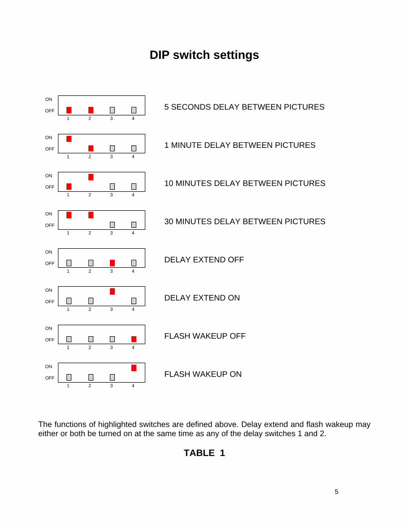
DIP switch settings
1 2 3 4
1 2 3 4
1 2 3 4
1 2 3 4
1 2 3 4
1 2 3 4
1 2 3 4
1 2 3 4
ON
OFF
ON
OFF
ON
OFF
ON
OFF
ON
OFF
ON
OFF
ON
OFF
ON
OFF
5 SECONDS DELAY BETWEEN PICTURES
1 MINUTE DELAY BETWEEN PICTURES
10 MINUTES DELAY BETWEEN PICTURES
30 MINUTES DELAY BETWEEN PICTURES
DELAY EXTEND OFF
DELAY EXTEND ON
FLASH WAKEUP OFF
FLASH WAKEUP ON
The functions of highlighted switches are defined above. Delay extend and flash wakeup may either or both be turned on at the same time as any of the delay switches 1 and 2.
TABLE 1
5
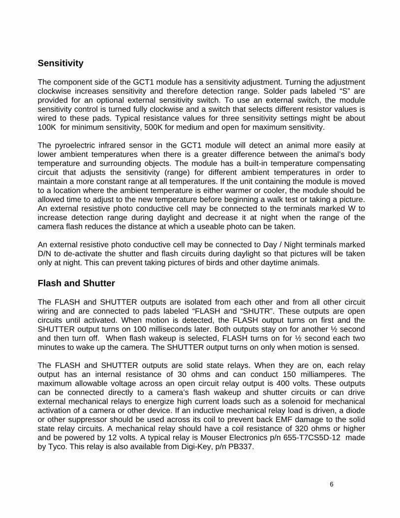
Sensitivity The component side of the GCT1 module has a sensitivity adjustment. Turning the adjustment clockwise increases sensitivity and therefore detection range. Solder pads labeled “S” are provided for an optional external sensitivity switch. To use an external switch, the module sensitivity control is turned fully clockwise and a switch that selects different resistor values is wired to these pads. Typical resistance values for three sensitivity settings might be about 100K for minimum sensitivity, 500K for medium and open for maximum sensitivity. The pyroelectric infrared sensor in the GCT1 module will detect an animal more easily at lower ambient temperatures when there is a greater difference between the animal’s body temperature and surrounding objects. The module has a built-in temperature compensating circuit that adjusts the sensitivity (range) for different ambient temperatures in order to maintain a more constant range at all temperatures. If the unit containing the module is moved to a location where the ambient temperature is either warmer or cooler, the module should be allowed time to adjust to the new temperature before beginning a walk test or taking a picture. An external resistive photo conductive cell may be connected to the terminals marked W to increase detection range during daylight and decrease it at night when the range of the camera flash reduces the distance at which a useable photo can be taken. An external resistive photo conductive cell may be connected to Day / Night terminals marked D/N to de-activate the shutter and flash circuits during daylight so that pictures will be taken only at night. This can prevent taking pictures of birds and other daytime animals. Flash and Shutter The FLASH and SHUTTER outputs are isolated from each other and from all other circuit wiring and are connected to pads labeled “FLASH and “SHUTR”. These outputs are open circuits until activated. When motion is detected, the FLASH output turns on first and the SHUTTER output turns on 100 milliseconds later. Both outputs stay on for another ½ second and then turn off. When flash wakeup is selected, FLASH turns on for ½ second each two minutes to wake up the camera. The SHUTTER output turns on only when motion is sensed. The FLASH and SHUTTER outputs are solid state relays. When they are on, each relay output has an internal resistance of 30 ohms and can conduct 150 milliamperes. The maximum allowable voltage across an open circuit relay output is 400 volts. These outputs can be connected directly to a camera’s flash wakeup and shutter circuits or can drive external mechanical relays to energize high current loads such as a solenoid for mechanical activation of a camera or other device. If an inductive mechanical relay load is driven, a diode or other suppressor should be used across its coil to prevent back EMF damage to the solid state relay circuits. A mechanical relay should have a coil resistance of 320 ohms or higher and be powered by 12 volts. A typical relay is Mouser Electronics p/n 655-T7CS5D-12 made by Tyco. This relay is also available from Digi-Key, p/n PB337.
6

Power A six to twelve volt battery will power the circuits. Power is connected to the PC module solder pads marked “POWER, + and –“. After the selected delay times out, the ready LED will blink indicating that the camera is ready to take another picture and most of the circuits will go into a sleep mode where the total current used by the module will drop to 35 microamperes. The motion detector part of the module remains active during sleep and will wake up the sleeping parts of the module when motion is detected. In average use, the GCT1 will draw only 35 microamperes most of the time. A nine volt alkaline battery should power the module for at least one year and possibly much longer. The average current will be a little higher when flash wakeup mode is selected because the circuits will wake up each two minutes to pulse the FLASH output for 100 milliseconds and wake up the camera. Installation A Fresnel lens can be mounted in an enclosure and held in place with tape or silicone rubber. There is no known effective adhesive that will bond to the lens material without the danger of damage to its surface. Although silicone rubber will not bond to the lens, it can be applied so as to overlap the edge of the lens and form a captive mount. For a secure waterproof seal, an O ring could be recessed into the inner surface of an enclosure and the lens flange held against it by an inner flange of metal or plastic that is held in place by screws or cement. The module PC board can be spaced away from the lens by threaded nylon spacers. If a FL65 Fresnel lens having a focal length of 0.65 inch is used and mounted against the inner surface of an enclosure, four 7/8 inch long threaded nylon spacers Digi-Key p/n 1902GK will mount the GCT1 module so that the sensor is the correct distance from the lens. Connect the shutter and flash terminals on the GCT1 to the shutter and flash contacts within the camera or connect only the shutter terminals if the camera does not have separate flash contacts. If the camera has a common contact for both shutter and flash, one shutter and one flash terminal on the GCT1 may be connected together and to the camera common contact. Shutter and flash terminals on the GCT1 are non-polarized and may be connected in either direction. Information on how to modify a camera for use with a motion detector can be found at http://www.jesseshuntingpage.com/camera-mods.html. After installing the module and wiring it into your application, close the test switch, apply power and wait 15 seconds for the circuits to stabilize and become active. If a ready LED is used, it will turn on for one half second. If the unit has been moved to a new location, allow time for temperature stabilization. Maximum detection range can be found by walking across the front of the sensor at increasing distances until the test light no longer lights. There is a one second delay between motion detection when in test mode. Range can be adjusted with the sensitivity control on the module or with an external control or switch if used.
7

ABSOLUTE MAXIMUM RATINGS
PARAMETER RATING UNITS Power supply voltage 1 15.0 Volts Flash open circuit output voltage 2 400 Volts Shutter open circuit output voltage 2 400 Volts Flash output current 3 150 Milliamperes Shutter output current 3 150 Milliamperes Voltage applied to any control terminal 4 5.3 Volts
Notes:
1. Voltage from + to – power terminals on PC board 2. Voltage across terminals when output is off 3. Load current when output is on 4. External voltage applied to any terminal other than power and outputs
TYPICAL OPERATION
PARAMETER MIN TYPICAL
MAX UNITS
Power supply voltage 5 5.5 9.0 14.5 Volts Flash open circuit output voltage 6 - 3.0 350 Volts Shutter open circuit output voltage 6 - 3.0 350 Volts Flash output current 7 - 1.0 150 Milliamperes Shutter output current 7 - 1.0 150 Milliamperes Voltage applied to any control terminal 8 - - 5.2 Volts
Notes:
5. Voltage from + to – power terminals on PC board 6. Voltage across terminals when output is off 7. Load current when output is on 8. External voltage applied to any terminal other than power and outputs
Ordering information______________
PART NUMBER DESCRIPTION GCT1 standard camera trigger module
8
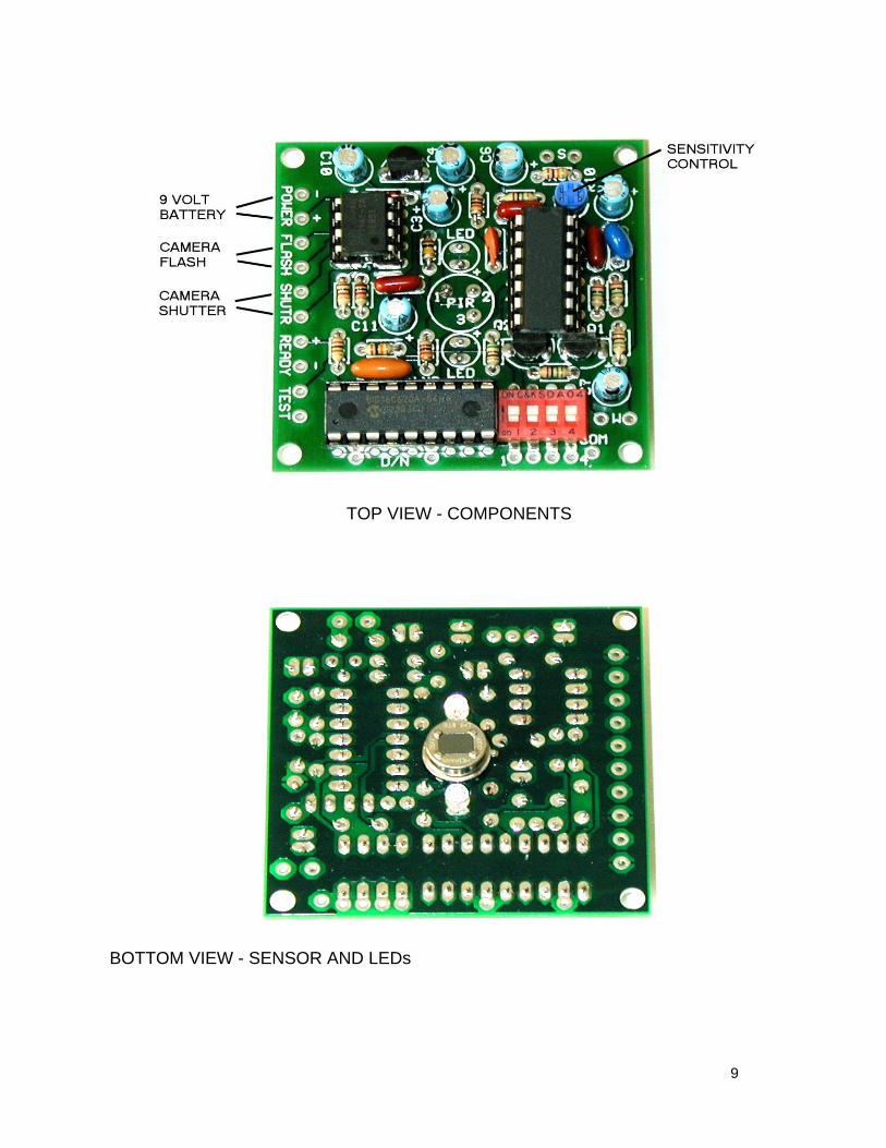
TOP VIEW - COMPONENTS
BOTTOM VIEW - SENSOR AND LEDs
9
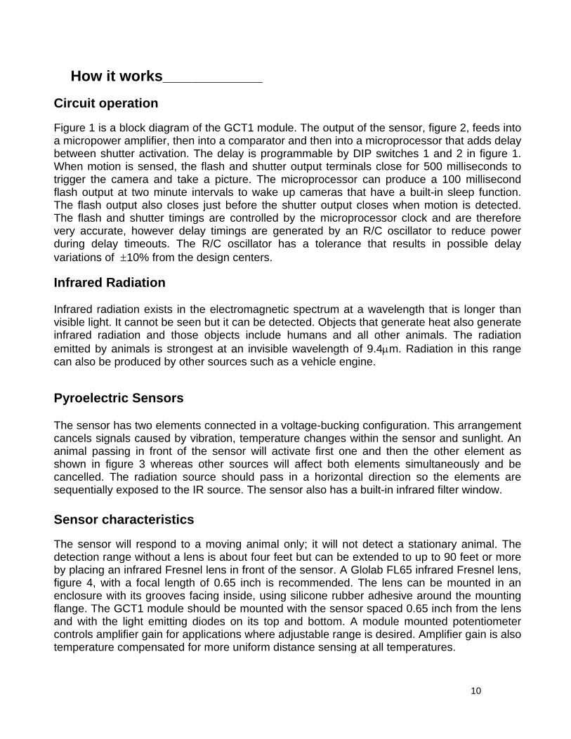
How it works____________ Circuit operation Figure 1 is a block diagram of the GCT1 module. The output of the sensor, figure 2, feeds into a micropower amplifier, then into a comparator and then into a microprocessor that adds delay between shutter activation. The delay is programmable by DIP switches 1 and 2 in figure 1. When motion is sensed, the flash and shutter output terminals close for 500 milliseconds to trigger the camera and take a picture. The microprocessor can produce a 100 millisecond flash output at two minute intervals to wake up cameras that have a built-in sleep function. The flash output also closes just before the shutter output closes when motion is detected. The flash and shutter timings are controlled by the microprocessor clock and are therefore very accurate, however delay timings are generated by an R/C oscillator to reduce power during delay timeouts. The R/C oscillator has a tolerance that results in possible delay variations of ±10% from the design centers. Infrared Radiation Infrared radiation exists in the electromagnetic spectrum at a wavelength that is longer than visible light. It cannot be seen but it can be detected. Objects that generate heat also generate infrared radiation and those objects include humans and all other animals. The radiation emitted by animals is strongest at an invisible wavelength of 9.4µm. Radiation in this range can also be produced by other sources such as a vehicle engine.
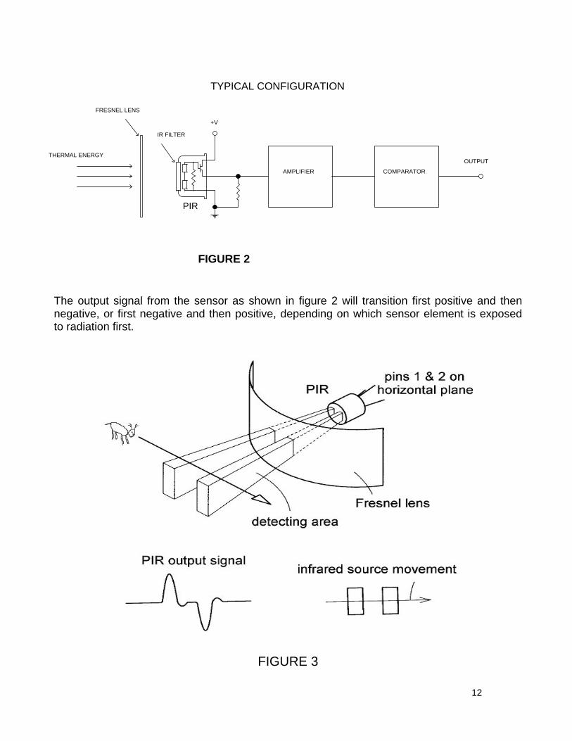
Pyroelectric Sensors The sensor has two elements connected in a voltage-bucking configuration. This arrangement cancels signals caused by vibration, temperature changes within the sensor and sunlight. An animal passing in front of the sensor will activate first one and then the other element as shown in figure 3 whereas other sources will affect both elements simultaneously and be cancelled. The radiation source should pass in a horizontal direction so the elements are sequentially exposed to the IR source. The sensor also has a built-in infrared filter window. Sensor characteristics The sensor will respond to a moving animal only; it will not detect a stationary animal. The detection range without a lens is about four feet but can be extended to up to 90 feet or more by placing an infrared Fresnel lens in front of the sensor. A Glolab FL65 infrared Fresnel lens, figure 4, with a focal length of 0.65 inch is recommended. The lens can be mounted in an enclosure with its grooves facing inside, using silicone rubber adhesive around the mounting flange. The GCT1 module should be mounted with the sensor spaced 0.65 inch from the lens and with the light emitting diodes on its top and bottom. A module mounted potentiometer controls amplifier gain for applications where adjustable range is desired. Amplifier gain is also temperature compensated for more uniform distance sensing at all temperatures.
10
AM
PLI
FIE
RC
OM
PA
RA
TOR
SE
NS
OR
LEN
SFR
ES
NE
L
MIC
RO
PR
OC
ES
SO
RR
ELA
YS
AN
IMA
LM
OV
ING
SW
D/N
TES
TR
EA
DY
12
34
CO
MS
HU
TRFL
AS
H
FIGURE 1
11
PIR
FRESNEL LENS
THERMAL ENERGY
+V
OUTPUT
COMPARATORAMPLIFIER
IR FILTER
TYPICAL CONFIGURATION
FIGURE 2
The output signal from the sensor as shown in figure 2 will transition first positive and then negative, or first negative and then positive, depending on which sensor element is exposed to radiation first.
FIGURE 3
12
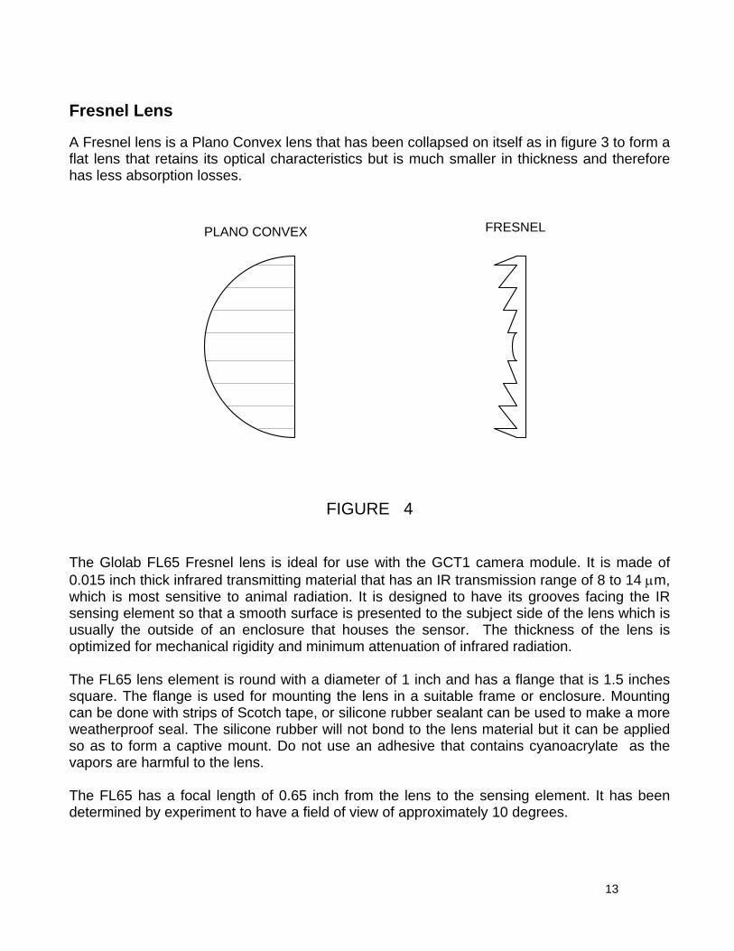
Fresnel Lens A Fresnel lens is a Plano Convex lens that has been collapsed on itself as in figure 3 to form a flat lens that retains its optical characteristics but is much smaller in thickness and therefore has less absorption losses.
PLANO CONVEX FRESNEL
FIGURE 4
The Glolab FL65 Fresnel lens is ideal for use with the GCT1 camera module. It is made of 0.015 inch thick infrared transmitting material that has an IR transmission range of 8 to 14 µm, which is most sensitive to animal radiation. It is designed to have its grooves facing the IR sensing element so that a smooth surface is presented to the subject side of the lens which is usually the outside of an enclosure that houses the sensor. The thickness of the lens is optimized for mechanical rigidity and minimum attenuation of infrared radiation. The FL65 lens element is round with a diameter of 1 inch and has a flange that is 1.5 inches square. The flange is used for mounting the lens in a suitable frame or enclosure. Mounting can be done with strips of Scotch tape, or silicone rubber sealant can be used to make a more weatherproof seal. The silicone rubber will not bond to the lens material but it can be applied so as to form a captive mount. Do not use an adhesive that contains cyanoacrylate as the vapors are harmful to the lens. The FL65 has a focal length of 0.65 inch from the lens to the sensing element. It has been determined by experiment to have a field of view of approximately 10 degrees.
13
Applications_______ The following pages show how external connections to the GCT1 are made and how external devices can be added to provide additional features. Optional external parts can be purchased from several parts distributors. Two are listed below. Mouser Electronics, 1-800-346-6873, www.mouser.comDigi-Key Corporation, 1-800-344-4539, www.digikey.com GCT1APP1. Remote sensitivity. The switch used in this application may be of the rotary type Mouser p/n 10YX043 or Digi-Key p/n EG1958 or may be a three position toggle switch with a center off Mouser p/n 108-MS550H. GCT1APP2. Day / Night control. A resistive photo conductive cell for this application is Digi-Key p/n PDV-P8001 that has a light resistance of 8K ohms in daylight and an dark resistance of 200K. These cells are non-polarized and may be connected in either direction. A SPST toggle switch Mouser p/n 108-MS550K can be connected in series with the cell to turn D/N sensing on and off. This cell can also be used to deactivate the circuit with a flashlight so the camera can be moved without taking a picture GCT1APP3. Night sensitivity. A resistive photo conductive cell Digi-Key p/n PDV-P8001 that has a light resistance of 8K in daylight and a dark resistance of 200K will work in this application when used with a 300K series resistor. These cells are non-polarized and may be connected in either direction. GCT1APP4. Ready LED. Almost any LED will work. A typical part is Mouser p/n 604-L7113SRD/D or Digi-Key p/n MV8191. GCT1APP5. Test switch. Any SPST toggle or other switch can be used. Typical Mouser p/n 108-MS550K GCT1APP6. Delay selector. An external DIP or rotary selector switch may be used. A typical 2 pole 4 position rotary selector switch is Mouser p/n is 10YX034 or Digi-Key p/n EG1956. GCT1APP7. Delay extend. A SPST toggle switch can be used. Typical Mouser p/n 108-MS550K. GCT1APP8. External relays. Since the solid state relay within the GCT1 has an internal resistance of 30 ohms, a mechanical relay that draws low current and has a 12 volt coil should be used for this application. A typical relay is Mouser p/n 655-T7CS5D-12 or Digi-Key p/n PB337 with contacts rated at 10 amperes. The relay coil should be shunted with a silicon diode Mouser p/n 625-1N914 or almost any other silicon diode. Only one relay is needed for applications where only the shutter output is used, for example, to power a solenoid.
14
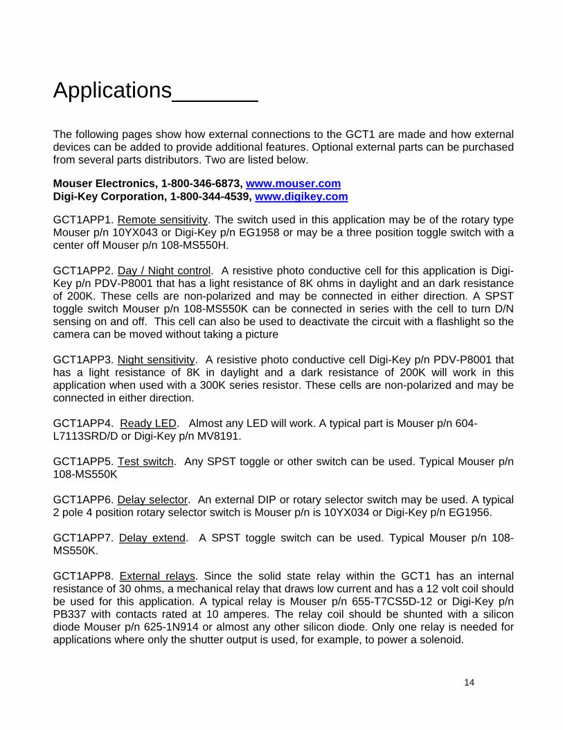
An external SENSITIVITY switch can be added to the S terminals as shown in figure GCT1APP1. The internal sensitivity control should be set fully clockwise to maximum resistance so that the external switch can control sensitivity. The switch may be a rotary or toggle type.
POWER
FLASH
SHUTR
READY
TEST COM
1 2 3 4
_
+
_
+
TO uP
TO uP
DELAY SELECT
TO CKTS
EXTERNALSENSITIVITYLOW
MEDIUM
HIGH 500K
S
R10 1MSENSITIVITY
TO CKT
W
D/N
100K
Figure GCT1APP1
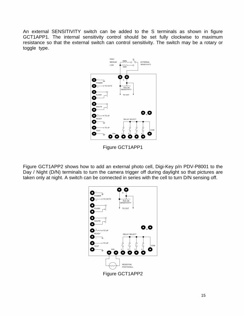
Figure GCT1APP2 shows how to add an external photo cell, Digi-Key p/n PDV-P8001 to the Day / Night (D/N) terminals to turn the camera trigger off during daylight so that pictures are taken only at night. A switch can be connected in series with the cell to turn D/N sensing off.
POWER
FLASH
SHUTR
READY
TEST COM
1 2 3 4
_
+
_
+
TO uP
TO uP
DELAY SELECT
TO CKTS
S
R10 1MSENSITIVITY
TO CKT
W
PHOTOCELLRESISTIVE
D/N
Figure GCT1APP2
15
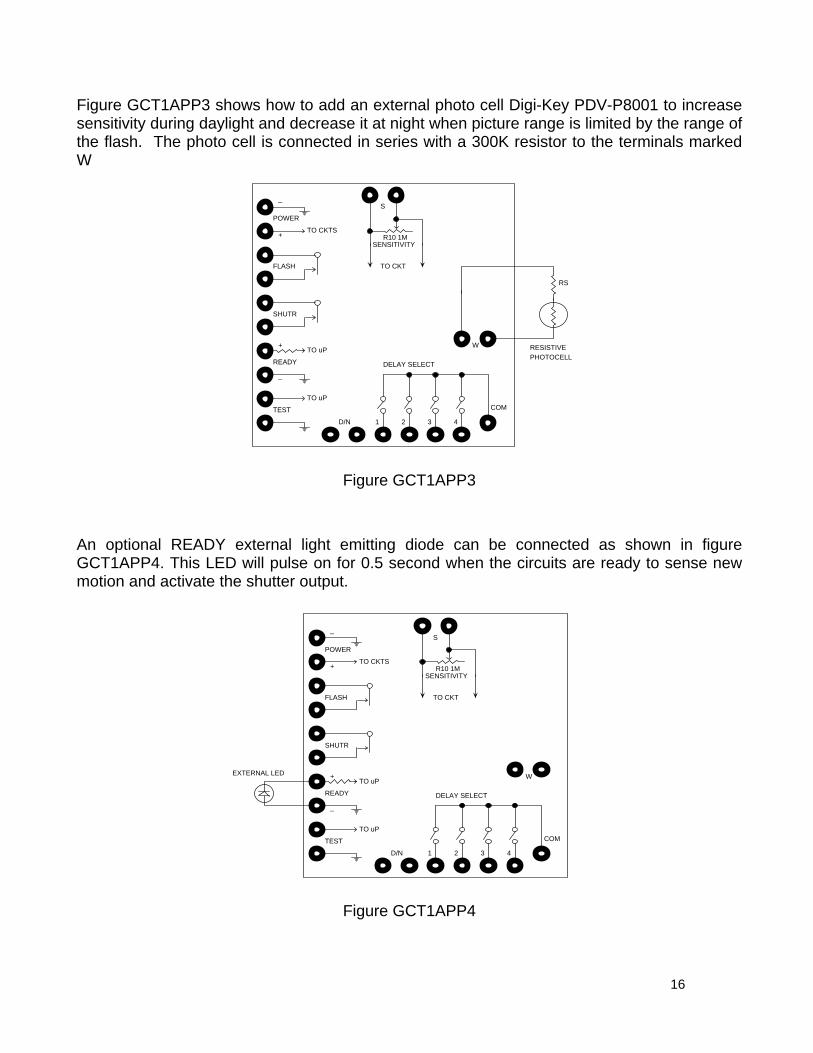
Figure GCT1APP3 shows how to add an external photo cell Digi-Key PDV-P8001 to increase sensitivity during daylight and decrease it at night when picture range is limited by the range of the flash. The photo cell is connected in series with a 300K resistor to the terminals marked W
POWER
FLASH
SHUTR
READY
TEST COM
1 2 3 4
_
+
_
+
TO uP
TO uP
DELAY SELECT
TO CKTS
S
R10 1MSENSITIVITY
TO CKT
W
PHOTOCELLRESISTIVE
D/N
RS
Figure GCT1APP3
An optional READY external light emitting diode can be connected as shown in figure GCT1APP4. This LED will pulse on for 0.5 second when the circuits are ready to sense new motion and activate the shutter output.
POWER
FLASH
SHUTR
READY
TEST COM
1 2 3 4
_
+
_
+
TO uP
TO uP
DELAY SELECT
TO CKTS
S
R10 1MSENSITIVITY
TO CKT
WEXTERNAL LED
D/N
Figure GCT1APP4
16
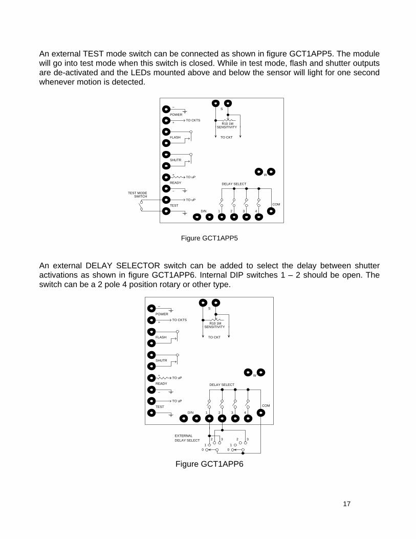
An external TEST mode switch can be connected as shown in figure GCT1APP5. The module will go into test mode when this switch is closed. While in test mode, flash and shutter outputs are de-activated and the LEDs mounted above and below the sensor will light for one second whenever motion is detected.
POWER
FLASH
SHUTR
READY
TEST COM
1 2 3 4
_
+
_
+
TO uP
TO uP
DELAY SELECT
TO CKTS
S
R10 1MSENSITIVITY
TO CKT
W
SWITCHTEST MODE
D/N
Figure GCT1APP5
An external DELAY SELECTOR switch can be added to select the delay between shutter activations as shown in figure GCT1APP6. Internal DIP switches 1 – 2 should be open. The switch can be a 2 pole 4 position rotary or other type.
POWER
FLASH
SHUTR
READY
TEST COM
1 2 3 4
_
+
_
+
TO uP
TO uP
DELAY SELECT
TO CKTS
S
R10 1MSENSITIVITY
TO CKT
W
10
2EXTERNALDELAY SELECT
D/N
10
23 3
Figure GCT1APP6
17
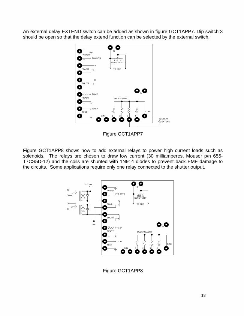
An external delay EXTEND switch can be added as shown in figure GCT1APP7. Dip switch 3 should be open so that the delay extend function can be selected by the external switch.
POWER
FLASH
SHUTR
READY
TEST COM
1 2 3 4
_
+
_
+
TO uP
TO uP
DELAY SELECT
TO CKTS
S
R10 1MSENSITIVITY
TO CKT
W
DELAYEXTEND
D/N
Figure GCT1APP7
Figure GCT1APP8 shows how to add external relays to power high current loads such as solenoids. The relays are chosen to draw low current (30 milliamperes, Mouser p/n 655-T7CS5D-12) and the coils are shunted with 1N914 diodes to prevent back EMF damage to the circuits. Some applications require only one relay connected to the shutter output.
POWER
FLASH
SHUTR
READY
TEST COM
1 2 3 4
_
+
_
+
TO uP
TO uP
DELAY SELECT
TO CKTS
S
R10 1MSENSITIVITY
TO CKT
W
+ 12 VDC
D/N
Figure GCT1APP8
18

WARRANTY STATEMENT WHAT DOES OUR WARRANTY COVER? • Any defect in material or workmanship. FOR HOW LONG AFTER THE ORIGINAL PURCHASE? • To the original purchaser only – 90 days HOW DO I SEND MY MODULE, IN OR OUT OF WARRANTY? • Fax to (845) 297-9772 or email to [email protected] for return authorization. • Properly pack your module, use anti-static packing. • Include a copy of the sales receipt or other evidence of date of original purchase (if the
module was purchased within the last 90 days). • Include a description of the defect. • Include payment for any service or repair not covered by warranty, as determined by
Glolab Corporation. • Ship the unit via FedEx insured or equivalent to: GLOLAB CORPORATION 307 PINE RIDGE DRIVE WAPPINGERS FALLS, NY 12590 WHAT DOES OUR WARRANTY NOT COVER? • Water or moisture damage. • Damage from misuse, neglect, or acts of nature (lightning, floods etc.). • Modules that have been operated beyond absolute maximum ratings. • Modules that may have been modified without authorization from Glolab Corp. • Modules purchased and/or operated outside the USA, its territories, or Canada. • Modules serviced by a service facility other than Glolab Corporation. • Other equipment that may or may not have been connected to this module. • Modules purchased more than 90 days from current date. LIMITS OF LIABILITY • No liability is assumed for any consequential damages resulting from the use of this
module. • Glolab is not responsible for nor warrants this module for merchantability or fitness for a
particular purpose. The information in this manual is believed to be accurate at the time of publication. However, Glolab assumes no responsibility arising from the use of the specifications described. The applications mentioned herein are used solely for the purpose of illustration and Glolab makes no warranty or representation that such applications will be suitable without further modification, nor recommends the use of its products for applications that may present risk to human life or to property due to malfunction or otherwise. Glolab reserves the right to change its design and specifications without prior notification.
19

GLOLAB CORPORATION 307 Pine Ridge Drive Wappingers Falls, NY 12590 voice - (845) 297-9771 Fax - (845) 297-9772 Email - [email protected] http://www.glolab.com © 2003 Glolab Corp.
20


