INFRASTRUCTURE DESIGN AND CONSTRUCTION STANDARDS December 15, 2006 Revised: December 31, 2007 Revised: May 10, 2005 (Resolution #050267) Prepared by ARAPAHOE COUNTY DEPARTMENT OF PUBLIC WORKS AND DEVELOPMENT Resolution No. 190242 Adopted April 19, 2019
Transcript
INFRASTRUCTURE DESIGN AND
CONSTRUCTION STANDARDS
December 15, 2006 Revised: December 31, 2007
Revised: May 10, 2005 (Resolution #050267)
Prepared by ARAPAHOE COUNTY DEPARTMENT
OF PUBLIC WORKS AND DEVELOPMENT
Resolution No. 190242
Adopted April 19, 2019
ACKNOWLEDGEMENTS
The Arapahoe County Department of Public Works and Development wishes to thank the following named individuals for their assistance and contributions that made this manual possible.
Project Managers
Scott Wiggs, PE, Engineer III Sue Liu, Engineer II
Arapahoe County Staff
Dave Schmit, PE, Director, Department of Public Works and Development Jim Pankonin, PE, Engineering Division Manager Chuck Haskins, PE Program Manager, Land Development Services Stacey Thompson, Engineer II Dan Slanina, Engineer II Ashley Byerley, Engineer I Jeff Scott, Chief Engineering Inspector Mick Fields, Engineering Inspector Polonia Koprowski, Engineering Inspector Jim Marks, Engineering Inspector Michelle Florman, Administrative Liz Ellis, Cover Design Melissa Kendrick, Program Manager, Planning Peggy Vana, Administrative
Technical Assistance
Structural Engineering Kenneth Hawkins, III, PE Hedrick & Associates 2455 West Main Street Littleton, CO 80120
Geotechnical Engineering Darrel Holmquist, PE CTL Thompson 2600 McHale Court, Suite 180 Austin, Texas 78758
Internal Review Committee
Bryan Weimer, Program Manager, Capital Improvements Program Brian Love, PE, Assistant Program Manager, Capital Improvements Program Steve Gardner, PE, Program Manager, Stormwater Management Jerry Mashka, Arapahoe County Traffic Engineer
Revised 12/27/06
TABLE OF CONTENTS
Chapter Title Page
1 GENERAL PROVISIONS 1.1
2 SUBMITTAL PROCEDURES 2.1
3 SUBMITTAL REQUIREMENTS FOR CONSTRUCTION PLANS 3.1
4 ROADWAY DESIGN AND TECHNICAL CRITERIA 4.1
5 PAVEMENT DESIGN AND TECHNICAL CRITERIA 5.1
6 BRIDGES AND MAJOR DRAINAGE STRUCTURES 6.1
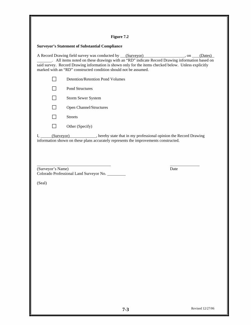
7 RECORD DRAWINGS 7.1
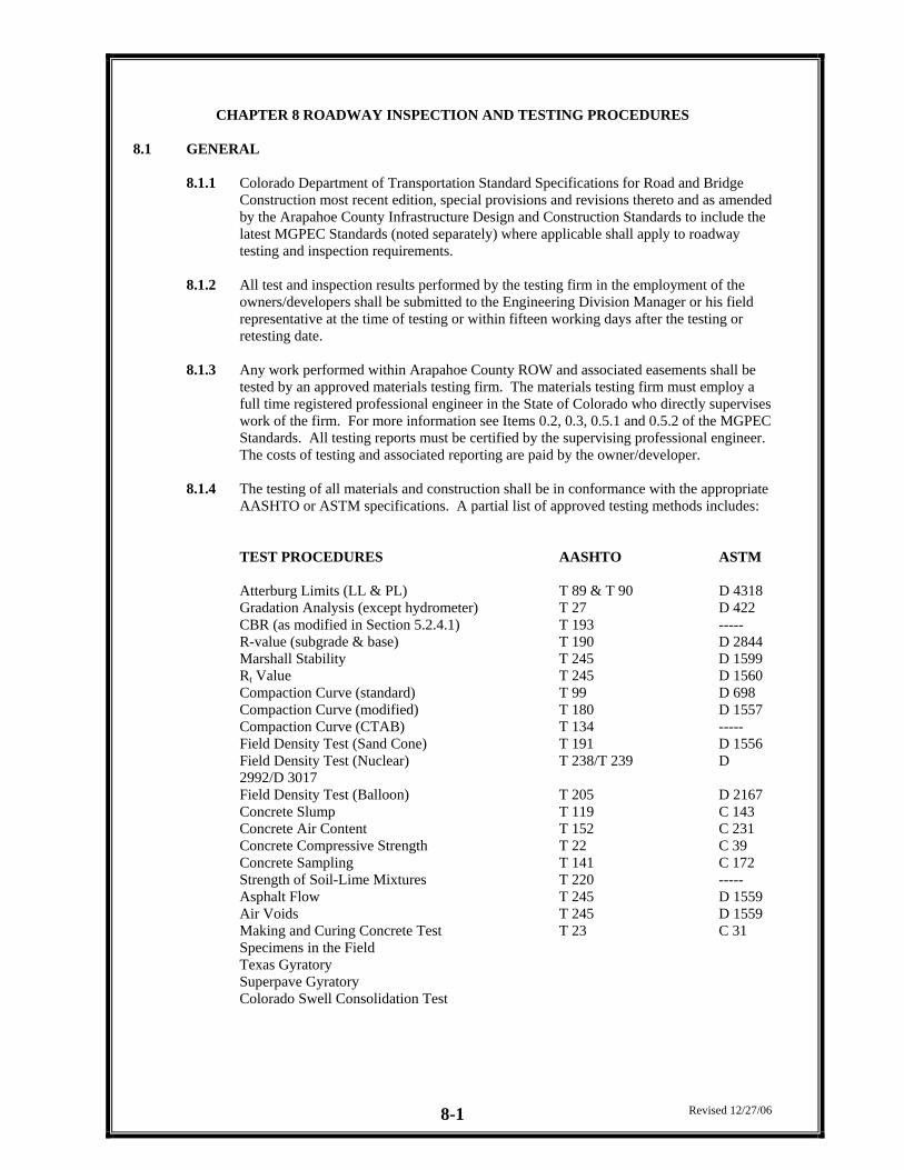
8 ROADWAY INSPECTION AND TESTING PROCEDURES 8.1
9 PERMIT, BONDING AND ACCEPTANCE REQUIREMENTS 9.1
10 UTILITY LOCATIONS 10.1
11 ACCESS REQUIREMENTS 11.1
12 PUBLIC IMPROVEMENTS COST ESTIMATE 12.1
13 FORMS 13.1
14 SMALL CELL WIRELESS COMMUNICATION FACILITY (WCF) 14.1 REGULATIONS
APPENDICES
APPENDIX A – STANDARD DETAILS
APPENDIX B – GUIDELINES FOR TRAFFIC IMPACT STUDIES
APPENDIX C – GUIDELINES FOR TRAFFIC CONTROL DURING CONSTRUCTION
APPENDIX D – CONSTRUCTION SPECIFICATION TOLERANCES
APPENDIX E - UTILITY LOCATE AND POTHOLE REPAIR
APPENDIX F – EXAMPLE COST ESTIMATE, COLLATERAL LETTER OF INTENT, &
IRREVOCABLE LETTER OF CREDIT
Revised 12/27/06
CHAPTER 1 GENERAL PROVISIONS
INDEX Section Topic Page 1.1 Short Title 1.1 1.2 Jurisdiction 1.1 1.3 Purpose 1.1 1.4 Enactment Authority 1.1 1.5 Amendment and Revisions 1.1 1.6 Enforcement Responsibility 1.1 1.7 Review and Approval 1.2 1.8 Interpretation 1.2 1.9 Relationship to Other Standards 1.2 1.10 Variances 1.2 1.11 Abbreviations 1.3
CHAPTER 1 - GENERAL PROVISIONS
1.1 SHORT TITLE These regulations, together with all future amendments, shall be known as the “Arapahoe County Infrastructure Design and Construction Standards” (hereinafter referred to as “Standards”) and are part of the Arapahoe County Subdivision Regulations (hereinafter referred to as “ Regulations”). The original Roadway Design and Construction Standards Manual was adopted by the Arapahoe County Board of County Commissioners (hereinafter called “BOCC”) by resolution in 1986. The previous manual is hereby repealed and replaced by these Standards.
1.2 JURISDICTION These Standards shall apply to all land within the unincorporated areas of Arapahoe County, except where the County’s jurisdiction is superseded by the State or by another jurisdiction.
1.3 PURPOSE These Standards present the minimum design and technical criteria for analysis and design of roadway facilities. All subdivisions, re-subdivisions, planned unit developments, or any other proposed construction submitted for approval under the provisions of the Regulations shall include adequate roadway system analysis and appropriate roadway system design. Such analysis and design shall conform to the criteria set forth herein. Options to comply with the provisions of these Standards may be provided by the applicant. However, it shall be the responsibility of the applicant to demonstrate that an option meets or exceeds the minimum criteria contained herein. Policies and technical criteria not specifically addressed in this document shall follow the design recommendations of the American Association of State Highway and Transportation Officials (AASHTO) “Policies on Geometric Design of Highways and Streets”, the latest edition and the “Standard Construction Specifications” of the Colorado Department of Transportation.
1.4 ENACTMENT AUTHORITY The Regulations are adopted pursuant to the authority conferred within: Article 28 of Title 30 (County Planning); Article 2 of Title 43 (State, County and City Highway Systems); Article 67 of Title 24 (Planned Unit Development Act); Article 20 of Title 29 (Land Use Control and Conservation); and other applicable sections of Colorado Revised Statutes, as amended. Pursuant to the above authority statutory, these Standards are adopted by resolution and are incorporated by reference as a part of the Regulations.
1.5 AMENDMENT AND REVISIONS The Standards may be amended from time to time as new technology is developed and/or the experience gained in the use of these Standards indicates a need for revision. Technical Modifications to these Standards shall be approved by the Director, Public Works and Development. Policy Changes within these Standards shall be approved by the BOCC, following the recommendations of the Director of the Department of Public Works and Development (or the Director’s named representative). The Director, Public Works and Development, shall monitor the performance and effectiveness of the Standards and will recommend changes, amendments or revisions, as needed.
Revised 12/27/06 1-1
1.6 ENFORCEMENT RESPONSIBILITY It shall be the duty of the Director of the Department of Public Works and Development, acting on behalf of the BOCC to enforce the provisions of these Standards.
1.7 REVIEW AND APPROVAL
The County shall review all submittals for general compliance to these Standards. Approval by the County does not relieve the owner, engineer or designer from responsibility of insuring that the calculations, plans, specifications, construction, and record drawings are in compliance with the Standards as stated in the owner’s and engineer’s certifications.
1.8 INTERPRETATION
In the interpretation and application of the provisions of the Standards, the following shall govern: 1.8.1. In their interpretation and application, these provisions shall be regarded as the minimum
requirements for the protection of the public health, safety, comfort, morals, convenience, prosperity, and welfare of the residents of the County. These Standards shall therefore be regarded as remedial and shall be liberally construed to further their underlying purposes.
1.8.2. Whenever a provision of these Standards and any other provisions of the Regulations or any
provision in any law, ordinance, resolution, rule, or regulation of any kind, contain any restrictions covering any of the same subject matter, whichever standards are more restrictive or impose higher standards or requirements shall govern.
1.8.3. These Standards shall not abrogate or annul any public improvement construction plans or
permits which have been filed with and approved prior to the effective date of these Standards, provided that the improvements have been constructed within the two-years from the date of approval. Public improvement construction plans or permits which have expired approvals (i.e. improvements have not been constructed, within two-years from the approval date) shall be required to be re-submitted in accordance with the requirements of these Standards. The Director shall have final authority to resolve any conflict in the interpretation of these Standards.
1.9 RELATIONSHIP TO OTHER STANDARDS
Since the County is the approval authority for land use changes, these Standards, which stipulate certain minimum conditions for land use changes, shall apply. If a special district imposes more stringent standards, this difference is not considered a conflict, and the more stringent standard shall apply. If the State or Federal Government imposes more stringent standards, criteria, or requirements, these shall be incorporated into this document after proper notice and public hearing(s) required modifying the County Regulations and Standards.
1.10 VARIANCES
Variances from these Standards will be considered on a case-by-case basis in accordance with procedures in the Regulations and Standards (refer to Section 3.2 of the Standards for variance procedure).
Revised 12/27/06 1-2
Revised 12/27/06 1-3
1.11 ABBREVIATIONS As used in these Standards, the following abbreviations shall apply: AASHTO American Society of State Highway & Transportation Officials AASHTO “GREEN” A Policy on Geometric Design of Highways & Streets ACI American Concrete Institute ASTM American Society of Testing Materials BOCC Arapahoe County Board of County Commissioners CDOT Colorado Department of Transportation CDOH Colorado Department of Highways (which name CDOT, CDOH and
stay consistent) FEMA Federal Emergency Management Agency IGA Inter-governmental Agreement MGPEC Metropolitan Governments Pavement Engineers Council MUTCD Manual on Uniform Traffic Control Devices OSHA Occupational Safety Hazard Administration PWD Public Works and Development ROW Rights-of-way SDDTC Arapahoe County Storm Drainage Design and Technical Criteria
Manual SIA Subdivision Improvement Agreement TSEA Traffic Signal Escrow Agreement UD&FCD Urban Drainage and Flood Control District USDCM Urban Storm Drainage Criteria Manual USGS United States Geological Survey
CHAPTER 2 - SUBMITTAL PROCEDURES
INDEX Section Topic Page 2.1 Drawings and Specifications Submittal Procedures 2.1 2.2 Revisions to approved Plans 2.3 2.3 Submittal Checklist 2.4 2.4 Drafting Standards 2.7 2.5 Fees and Penalties 2.7
CHAPTER 2 - SUBMITTAL PROCEDURES
2.1 DRAWINGS AND SPECIFICATIONS SUBMITTAL PROCEDURE
2.1.1 Overview Consulting engineers and developers seeking approval and acceptance of civil engineering reports and construction plans are required to follow the procedures outlined herein. Your adherence to these procedures will assist in an efficient review of engineering plans and reports. Submittal procedures and requirements for the various County land development processes can be found in the County’s Land Development Code and in a Planning Division publication "Land Development Application Guide."
2.1.2 Presubmittal Meetings
The Planning Division routinely conducts presubmittal meetings at which time applicants ask questions about the various County land development processes, obtain direction or information from Planning and Engineering Staff. These meetings may be used by the applicant to obtain very basic information about County procedures, requirements, or standards as a basis to begin development planning. Alternatively, the applicant may use the meeting as a final check by staff to verify if a specific type of application is complete.
2.1.2.1 Division of Engineering Presubmittal Meetings
The Land Development Services Section of the Engineering Division will reserve time for the purpose of meeting with applicants who plan to submit public improvement construction plans. In this meeting, the applicant may consult with the County Engineering Division for general information regarding applicable design criteria, required procedures, drainage concerns and submittal requirements.
2.1.3 Land Use Plan Submittals
Land use applications submitted to the Planning Division for all subdivisions or developments, whether residential, retail, commercial or office, shall include Preliminary Construction Drawings and Reports for the proposed development. The Preliminary Construction Plans shall be a minimum of 50% complete at the time of initial submittal. Construction Plans at 50% complete shall include, preliminary roadway and storm sewer profiles non-detailed grading plans, horizontal control plans, overall utility plan and standard design details. Construction plans shall be a minimum of 75% complete for acceptance of the Engineer’s Cost Estimate. Estimates of Public Improvements and the associated Improvements Agreement.
2.1.3.1 County acceptance of the Construction Plans constitutes:
− Engineering Division review and acceptance of the final design concept shown on the Construction Plans.
− Engineering Division concurrence with the Engineer’s Cost Estimate of Public
Improvements, as defined in Chapter 12.
− Engineering Division review and acceptance of an Improvement Agreement as defined in the Arapahoe County Publication “Understanding Improvement Agreements”, Latest Edition.
Revised 12/27/06 2-1
2.1.3.2 Approval of the Final Construction Plans shall be completed prior to the issuance of any Land Development Construction Permits. Approval of the Final Construction Plans shall not occur prior to final approvals of the associated land use application.
2.1.4 Engineering Review Objective
The Engineering Division objective is to issue comments on Construction Plans prior to the Planning Commission hearing, or within 30 calendar days if a Planning Commission hearing is not applicable, however, the actual time required is a function of the submittal complexity and overall workload of the Engineering Division. In the event the Construction Plans are submitted as part of a Land Use Case the review time shall coincide with the time allowed for the case submittal review as set forth by the Planning Division. The applicant will be advised of the estimated completion date for review of submitted documents.
2.1.5 Results of Engineering Review
After the review is completed, comments and/or redlines along with the disposition copy of the Application for Review and Approval, AC Form 581 (See Chapter 13 for an example copy of this form), will be returned to the applicant or his representative. The applicant or his representative will be notified by phone when the submittal is ready to be picked up, or if the applicant chooses, the information will be mailed out. If the Construction Plans are returned to the consultant for lack of adequate information or are considered seriously deficient, any resubmitted plans shall be considered a new submittal.
2.1.6 Developer Revision of Engineering Plans and Reports
The applicant’s representative shall make all the requested revisions on their original plans/report and resubmit according to the instructions. Seriously deficient plans or plans encompassing a significant area may require several reviews prior to approval. In the event the applicant does not address the comments issued by the Engineering Division, Staff reserves the right to re-assess fees based on the requirements set forth in the most recent Engineering Fee Schedule.
2.1.7 Submitting Revised Plans
When submitting revised plans or reports to the Engineering Division, the resubmittal must contain:
1. A completed application for Review and Approval (AC Form 581).
2. The revised plans and/or reports.
3. All redlines from previous Staff reviews, and a point by point response to staff
comments.
4. Review fees, if applicable.
If all the above items are not included with the submittal package submitted, the resubmittal may be returned without further action until such time as they are included.
Revised 12/27/06 2-2
2.1.8 Number of Plans for Approval Required Once plans and/or reports have been accepted for approval by the Engineering Division, the Applicant’s representative shall submit to the Engineering Department a minimum of five (5) sets of blackline copies of the Construction Plans & Reports. All five (5) sets must be signed and stamped by a Professional Engineer, registered in the State of Colorado. The Engineering Division will approve Construction Plans and Reports by signing all five (5) sets. One (1) set of signed plans / reports will be returned to the Applicant’s and four (4) sets of signed plans / reports shall be retained by the Engineering Division for County Records. The representative may also submit additional signed sets of Construction Plan and Report blacklines to be approved and signed by the Engineering Division for use by the, owner / developer, consultant, contractors, etc. Arapahoe County will not approve copies that have not been signed and stamped by a professional engineer.
2.1.9 Time Needed for Final Approval after Submittal The maximum length of time needed to process resubmitted final Construction plans will be ten (10) working days. This time may be extended under unusual conditions of workload.
2.1.10 Priority of Submittals
The Engineering Division’s policy on processing submittals. Applications are prioritized on a first come, first serve basis categories, no exceptions:
1. Blackline copies for approval by County 2. Resubmittal 3. Initial submittal
Complete submittals are those, which include all drawings and supporting reports. Partial or incomplete submittals that are missing one or more items applicable to the review process may be, at the discretion the Engineering Division, held or returned until all required information is submitted. If you have any questions regarding what constitutes a complete submittal for a specific project, call the, Land Development Services Section, of the Engineering Division.
When partial or incompleted plans are returned to the applicant, the resubmittal of those plans will be considered an initial submittal. Additional review fees may be assessed. 2.2 REVISIONS TO APPROVED PLANS
2.2.1 Plan Expiration and Extensions Construction plans, pavement design reports, drainage reports, and other technical documents are approved initially approved for twenty-four (24) months. If the improvements are not constructed during this time period and the plans expire, the applicant must resubmit the plans for standard re-approval.
2.2.2 Revisions to Approved Plans
Whenever updates or revisions to previously approved construction plans, specifications or drainage reports are necessary, the applicant will submit updates or revisions through the normal document submittal process. After all the Engineering Division comments and revisions have been incorporated, the blackline sheets containing revisions may be submitted for approval by the applicant. This approval submittal shall meet requirements of 2.1.8.
Requests for updates and revisions to construction plans will be considered only if there are NO impacts to the original development plan(s) or drainage report. The County will review the original development plan(s) or drainage report for compliance with current standards under normal review procedures (requests for updates will be considered resubmittals), and if found in compliance with current standards, the construction plan(s), pavement design report(s), or drainage report(s) will be approved.
Revised 12/27/06 2-3
2.2.3 Field Changes Minor changes to construction plans can be made in the field provided that the Engineering Division approves the changes prior to implementation. Failure to receive approval of field changes from the Engineering Division may result in non-acceptance of the facility. All field changes must be accurately depicted on the record drawings as defined in Chapter 7. The applicant shall provide to the Engineering Division a letter, signed and sealed by the Professional Engineer responsible for the original design stating that the proposed field change shall not deviate from the intent of the original design.
2.3 SUBMITTAL CHECKLIST
2.3.1 Final Construction Plans and supporting documents are required for all public improvements and improvements within Arapahoe County rights-of-ways, this applies to all land development applicants Metropolitan District improvements, special purpose district public improvements, or other improvements in Arapahoe County Right-of-Way. Approval authority is the Director, Public Works and Development.
2.3.1.1 A completed Application for Review & Approval (Form 581). 2.3.1.2 Engineering Review & Approval Fee.
2.3.1.3 Street Plan and Profile.
2.3.1.4 Storm Sewer Plan and Profile as recommended in the Phase III Drainage Report,
including details for all structures and material specifications.
2.3.1.5 Culvert plan, profile and construction detail for structures.
2.3.1.6 Detailed Grading Plan – Grading plans that include relevant spot elevations including, but not limited to, high and low points, Points of Curvature, Points of Tangency and Points of Curb Return. Include the detailed Grading, Erosion and Sediment Control Plans within the Grading plan set.
2.3.1.7 Horizontal Control Plan – Provides detail of the proposed horizontal layout of the site
including, but not limited to, line and curve information, parking lot dimensions, building setback dimensions, etc.
2.3.1.8 Traffic Signing and Striping Plan including Traffic Signal Phasing Plans. 2.3.1.9 Traffic Signal plans if applicable.
2.3.1.10 Pavement Thickness Design Report with supporting geotechnical information Note:
Final Construction Plans may be signed without a Final Pavement Design. An appropriate note indicating (1) a preliminary design basis or (2) that no design is complete, must be included. No pavement construction permits will be issued without an approved pavement design (See Chapter 5).
2.3.1.11 Landscaping Plans in conformance with Arapahoe County Streetscape Guidelines and
Section 3.19 of the Standards. Landscape and irrigation Plans for improvements located within County Right-of-Way shall be submitted as a separate document from the Construction Plans.
2.3.1.12 All utility construction plans as approved by the governing district or utility. If
installation within existing County roads, they must be approved by the County (see 2.3.5). If these plans are for lines to be installed with the proposed roadways, the plans are provided for information only.
2.3.1.13 If not previously approved, the Phase III Drainage Report (see Storm Drainage Design
and Technical Criteria, Section 2.4).
2.3.1.14 Public Improvements Cost Estimate.
Revised 12/27/06 2-4
2.3.2 Pavement Design Report
When the pavement design report is not submitted as a part of a Final Construction Plans, an Application for Review and Approval of the Pavement Design Report shall be submitted. The Director, has the authority for approval. The Pavement Design Report shall be completed prior to issuance of any permits, in the event of excessive cut/fill (more than five (5) feet) the applicant shall submit a Preliminary Pavement Design and follow up with a Design Confirmation Report prior to paving operations commencing. The submittal of the Pavement Design Report must include the following: 2.3.2.1 A completed Application for Review & Approval (Form 581).
2.3.2.2. Engineering Review & Approval fee.
2.3.2.3 Proposed design and alternatives including a geotechnical engineering report (refer to
Chapter 5 of the Standards).
2.3.3 Phase III Drainage Report When the Phase III Drainage report is not submitted as a part of a Final Construction Plans, an Application for Review and Approval of the drainage report shall be submitted. The approval authority is the Director, Public Works and Development. 2.2.3.1 A completed Application for Review & Approval (Form 581).
2.2.3.2 Engineering Review & Approval Fee.
2.3.3.3 A drainage report & plan including all the requirements identified with the Storm Drainage Design & Technical Criteria Manual (latest revisions).
2.3.3.4 A review and approval fee shall be paid by the applicant for a submitted Phase III
Drainage Report.
2.3.4 Final Construction Plans for County Roadway Access When access to a County roadway is proposed and the request is not part of a land use application. Final Construction Plans of the improvements are required. The Director has the authority for approval. The submittal of the Final Construction Plans shall include the following:
2.3.4.1 A completed Application for Review and Approval (Form 581). 2.3.4.2 Engineering Review and Approval fee.
2.3.4.3 Plan and profile of the existing street(s) showing construction details of the access
point(s). The plan and profile grades of the existing streets are to be shown a minimum of 150’ in each direction of the access point(s). At the discretion of the County’s Engineer, the plan and profile of the existing street may be required to be extended beyond the minimum distance.
2.3.4.4 The Engineering Division reserves the right to restrict traffic movements in the future.
Revised 12/27/06 2-5
2.3.5 Final Construction Plans for Utility Work in Arapahoe County Right-of-Way For new installations or major extensions of utility lines that are proposed within the County Right-of-way and/or under existing County roadways, an Application for Review & Approval shall be submitted. These requirements do not apply to maintenance work or service taps from existing mains to new users. The Director has the authority of approval. Refer to Chapter 9 of these Standards for Permit Bonding and Inspection Requirements for Street Cut and R.O.W Use
Permit applications. Utility Design and Construction shall conform to the requirements in Chapter 10 of these Standards. The submittal of the Utility Plans shall include the following information:
2.3.5.1 A completed Application for Review and Approval (Form 581).
2.3.5.2 Engineering Review and Approval fee. 2.3.5.3 Street plan and profile including the location of the street cuts, size and location of
utilities being repaired, replaced or constructed.
2.3.5.4 Specifications and construction details of trench backfill, compaction, and roadway reconstruction, as described within Chapter 8 of these Standards. This information can be provided through notes and details.
2.3.5.5 Plan for traffic control during construction (may be supplied by contractor prior to permit
issuance).
2.3.6 Revisions or Updates to Approved Final Construction Plans When revisions or updates to previously approved Construction Plans are proposed, an Application for Review and Approval shall be submitted. The Director has the authority for approval. The submittal of the Revisions or Updates shall include the following information:
2.3.6.1 A completed Application for Review and Approval (Form 581).
2.3.6.2 Engineering Review and Approval fee.
2.3.6.3 Letter stating the scope and purpose of the construction plan revisions.
2.3.6.4 The previously approved construction plan sheets, marked up with revisions.
2.3.6.5 The revised final construction plan sheets, including all appropriate notes and details.
2.3.6.6 Referral to other approving agencies (additional copies required).
2.3.7 Striping and/or Signing Plan
When Signing and Striping Plans are not submitted with the Final Construction Plans, an Application for Review and Approval of the Signing and Striping Plans shall be submitted. The Director has the authority for approval. The submittal of the Signing and Striping Plans shall include the following:
2.3.7.1 A completed Application for Review and Approval (AC Form 581).
2.3.7.2 Engineering Review and Approval fee.
2.3.7.3 Plan of the existing signing and striping, see Chapter 3, Section 3.16. 2.3.7.4 Plan of proposed signing and striping, see Chapter 3, Section 3.16.
2.3.7.5 No review fee need accompany the application if Arapahoe County is contracted to
install the signs.
2.3.7.6 If the Applicant is to furnish and install the signs/striping, the Engineering Review and Approval Fee shall be that for final construction.
Revised 12/27/06 2-6
2.3.8 Grading, Erosion, and Sediment Control (GESC) Plans and Report
Revised 12/27/06 2-7
The GESC Plans and Report are required to be submitted as a separate stand alone documents for review and approval. Please refer to the GESC Manual for the submittal requirements. The Director has the authority of approval. The submittal of the GESC Plans and Report shall include the following: 2.3.8.1 A completed Application for Review and Approval (Form 581).
2.3.8.2 Engineering Review and Approval fee.
2.3.8.3 GESC Plans and Reports in accordance with the GESC Manual.
2.3.9 Landscaping and Irrigation Plans Landscaping and Irrigation Plans are required for any landscaping proposed within or adjacent to County Rights-of-Way and/or County easements. The improvements could affect sight distances, drainage characteristics, structural stability of existing or proposed public improvements, or other safety issues. Chapter 3, Section 3.19 of the Standards and the Arapahoe County Land Development Code, Streetscape Guidelines latest edition. The submittal of the Landscaping and Irrigation Plans shall include the following:
2.3.9.1 A completed Application for Review and Approval (Form 581).
2.3.9.2 Engineering Review and Approval fee.
2.3.9.3 Landscaping and Irrigation Plans. Landscaping and Irrigation Plans including but not limited to, location and description of all proposed vegetation, irrigation lines, proposed street cuts, direction of drainage flows, street names, vicinity map, key map, general notes and the signature block.
2.4 DRAFTING STANDARDS 2.4.1 General
All plans submitted for approval and recordation shall meet the following minimum standards to facilitate microfilming. A. Plans shall be 24” x 36”. Final plans shall be blackline originals. B. Double plan and profile sheets will not be allowed. C. Development plans shall meet current Arapahoe County drafting standards, which are
available from the Mapping Section of the Engineering Division.
2.4.2 Lettering Letter size shall not be less than one-tenth (0.10) of an inch. (Number 100 Leroy template).
LETTERING USED ON ENGINEERING DRAWINGS, WHETHER BE FREEHAND, TYPED, OR THE USE OF A LETTERING GUIDE WILL, BE GREATER THAN OR EQUAL TO A NUMBER 100 LETTERING GUIDE (0.10). ALL LETTERING MUST BE IN SHARP CONTRAST WITH THE BACKGROUND OF THE ORIGINAL LETTER SIZE AND CONTRAST IS A MUST FOR MICROFILMING ENGINEERING DRAWINGS FOR RECORDS AND SECURITY NEEDS. THIS PARAGRAPH DEMONSTRATES THE MINIMUM ALLOWABLE LETTER SPACING (MAXIMUM DENSITY).
2.5 FEES AND PENALTIES Submittal Fees and Penalties shall be assessed in accordance with the current Engineering Fee Schedule.
CHAPTER 3 – SUBMITTAL REQUIREMENTS FOR CONSTRUCTION PLANS
INDEX
Section Topic Page 3.1 General 3.1 3.2 Variances, Waivers and Appeals 3.2 3.3 Vicinity Map 3.3 3.4 Key Map 3.3 3.5 Construction Plans and Detail Sheets 3.4 3.6 Cover Sheet 3.4 3.7 Approval Block 3.4 3.8 Required Notes 3.5 3.9 Scale 3.6 3.10 North Arrow 3.6 3.11 Date of Plan 3.6 3.12 Seal and Signature 3.6 3.13 Underground Utilities 3.6 3.14 Private Improvements 3.7 3.15 Requirements for Roadway Plan & Profiles 3.7 3.16 Signing and Striping Plan 3.10 3.17 Details 3.13 3.18 Range Points – Property Monuments – Benchmarks 3.13 3.19 Landscape Plans 3.13
Revised 06/03/09 3-1
CHAPTER 3 – SUBMITTAL REQUIREMENTS FOR CONSTRUCTION PLANS
3.1 GENERAL
The following information is required with the submittal of construction plans for any roadway or storm drainage improvement that will ultimately be maintained by Arapahoe County Public Works and Development (PWD). Private improvements may be reviewed for public safety. 3.1.1 All Construction Plans, Phases II and III Drainage Reports, Geotechnical
Reports/Pavement Designs shall be prepared by or under the direction of a Professional Engineer, registered in the State of Colorado, and shall be reviewed for the minimum requirements set forth herein. The Professional Engineer should be aware that additional information and analysis, beyond the minimum requirements, may be required for a proposed project, if unusual conditions or construction challenges are anticipated.
3.1.2 Certification
3.1.2.1 Preliminary Construction Plans submitted for review shall be prepared by a
Professional Engineer, registered in the State of Colorado. The plans must include the following statement on the cover sheet:
“I hereby affirm that these (preliminary/final) construction plans for (name of subdivision, development or project) were prepared by me (or under my direct supervision) in accordance with the requirements of the Infrastructure Design and Construction Standards and the Stormwater Management Manual.”
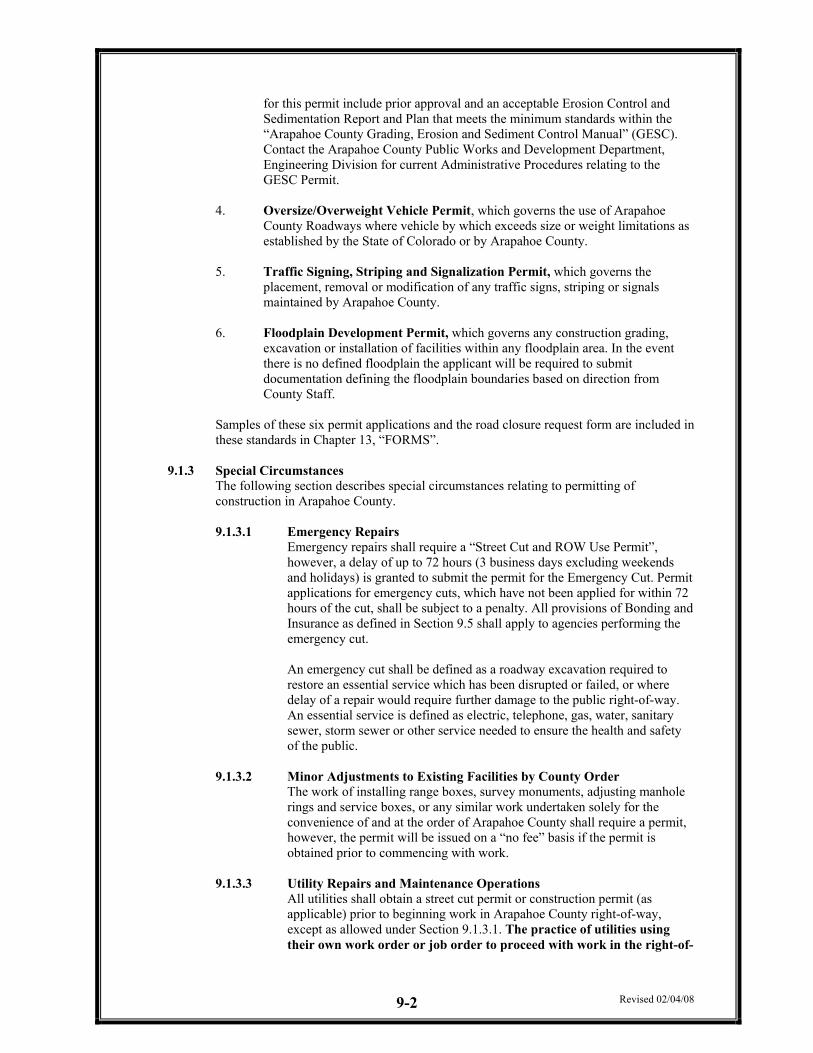
Name of Engineer PE Number Name of Engineering Firm
This statement shall be signed, stamped and dated by the Registered Professional Engineer who prepared or directed the preparation of the plans.
3.1.2.2 Final Construction Plans submitted to Arapahoe County for approval shall contain the affirming statement in 3.1.2.1. The statement shall be signed and stamped by the Registered Professional Engineer (Colorado Registration required) who prepared the plans, or directed the preparation of the plans.
3.1.2.3 Unless otherwise identified or noted, all construction plan submittals are
assumed to comply with the requirements of these Standards and the Drainage Criteria. Variances or waivers of the Standards or Drainage Criteria should be formally requested of the Engineering Division, as set forth in Section 3.2.1. Failure to comply with prescribed procedures may result in review delays, additional review fees, or both.
3.1.3 The policy and practice of Arapahoe County is not to accept the liability for facilities
designed by others. Arapahoe County does not accept responsibility for the accuracy and adequacy of the design. The County Engineer, through approval of the Construction Plans, indicates the Engineering Division has reviewed the document and found it in general compliance with the Regulations, Standards and Drainage Criteria, or approved variances thereof.
Revised 06/03/09 3-2
3.2 VARIANCES, WAIVERS AND APPEALS
3.2.1 General
If a special district, developer, contractor or utility provider responsible for public improvements proposes to design and construct improvements in variance to the criteria of these Standards, variance request(s) shall be submitted to the Engineering Case Manager and the Technical Review Committee (TRC) for review and recommendation. The variance request(s) are required to be identified with the initial submittal of Final Construction Plans. The variance request(s) shall consist of: 3.2.1.1 Identification of the criteria requested to be waived or varied. 3.2.1.2 Identification of the alternative design or construction criteria.
3.2.1.3 Justification for the variance or waiver request(s), including potential
impact to the capital maintenance costs.
3.2.2 Appeal of Variance Decisions
3.2.2.1 Levels of Appeal If the Engineering Case Manager or the TRC denies a variance or waiver request, the appeal process consists of two levels:
1. Appeal to the Director.
2. Appeal to the BOCC.
3.2.2.2 Appeal Procedure and Timing
If a variance or waiver request (see section 3.2.1) is denied, the applicant may appeal the decision. The appeal process is as follows:
1. Appeal to the Director, Public Works and Development
Within six (6) working days of receipt of a written appeal of a TRC variance recommendation, the Director shall respond in writing to the applicant, defining a date, time and location at which the applicant may present his appeal. The date of the meeting shall not be more than twelve (12) working days from the date of receipt of the written appeal.
At the appeal meeting it shall be the responsibility of the applicant to clearly define and justify the variance or waiver requested. Staff shall be responsible for presenting the reasons and basis for denying the original variance request.
The Director shall provide a written recommendation to the applicant within five (5) working days of the appeal meeting.
2. Appeal to the Board of County Commissioners (BOCC) If the Director upholds the TRC’s recommendation for denial of a variance request, the applicant may make a final administrative appeal to the BOCC. The appeal should be made directly through the Engineering Case Manager. The Engineering Case Manager will be responsible for scheduling the appeal through the Board of County Commissioners. The appeal should include:
Revised 06/03/09 3-3
1. The variance or waiver being requested with a brief
justification for the variance or waiver request. 2. The written recommendations from Staff and the Director for
the variance or waiver request, including the variance request from the applicant.
3. The estimated amount of time required to present the appeal to
the BOCC.
It is strongly recommended that the appeal of the variance or waiver request be taken to the BOCC with the land use application(s). If the appeal is taken to the BOCC prior to the public hearing for the land use application(s), the BOCC cannot be given specific information related to the land use application to render a decision on the appeal. The County Attorney’s Office shall schedule a public hearing agenda item at the next available hearing date. The applicant shall be notified of the hearing date for the appeal within six (6) working days of receipt of the written appeal. The appellant shall make his presentation before the BOCC within the time requested in the written appeal. The Public Works and Development Department shall have the opportunity to rebut the appeal presentation with a brief summary of findings of fact, description of circumstances and staff judgment used in the initial and appeal decisions.
3.3 VICINITY MAP
3.3.1 The Vicinity Map shall be to scale at a minimum of 1”=2000’. The Vicinity Map should include the location and names of all arterial roadways within one mile of the proposed construction, and all other roadways in the vicinity of the proposed construction. The Vicinity Map should also include the major drainage ways in this area. Shading shall indicate the project area. This map is required on the cover sheet or first sheet of all submittals.
3.3.2 The minimum size of the Vicinity Map is 3” x 3”.
3.3.3 The Vicinity Map cannot include any portion of the map that is copyrighted. The
Construction Plans will be part of the public record, where copyrights are prohibited. 3.4 KEY MAP
3.4.1 The Key Map shall be to scale at a minimum of 1”=500’. The Key Map should include the location and name of all roadways within and adjacent to the proposed construction, including future roadways being developed. The Key Map should include a north arrow.
3.4.2 A Key Map is required on every sheet showing proposed roadway, storm drainage or
grading improvements. The proposed roadway, storm drainage or grading area improvements on each sheet shall be shaded.
3.5 CONSTRUCTION PLANS AND DETAIL SHEETS
All construction plans and detail sheets shall include the following information.
Revised 06/03/09 3-4
3.6 COVER SHEET
The Cover Sheet shall contain the following information: 1. Project Name 2. Standard and Additional Notes, if applicable 3. Approval Block 4. Sheet Index 5. Vicinity Map 6. Arapahoe County Case Number (lower, left-hand corner) 7. Certification Statements 8. Legal Description 3.6.1 Title Block
A title block is required on every sheet. The following information shall be included in the title block: 1. Subdivision Name and Filing Number 2. Development Plan Name 3. Type of Improvements 4. Name, address, zip code, and telephone number of the consulting engineer 5. Name, address, zip code, and telephone number of the developer or contact
representative 6. Sheet Number
3.6.2 The title block shall be located in the lower right-hand corner, the right side margin or along the bottom edge of the sheet.
3.7 APPROVAL BLOCK
3.7.1 All construction plans for roadways, storm sewer, and drainage improvements, must
show the approval signature of the Director, Public Works and Development as a condition of Construction Permit issuance. Stormwater detention or retention facilities, etc. must show the approval signature of the Director prior to the issuance of construction permits.
3.7.1.1 Plans for traffic control during construction must be approved prior to the
issuance of construction permits. 3.7.1.2 Signing and Striping plans require the approval from the Traffic Section, if
the plans are not included in the overall Public Improvements Construction Plans.
3.7.2 The approval block shall be located in the lower right-hand corner of the sheet. 3.7.3 An example approval block is shown on Figure 3.1.
FIGURE 3.1 COUNTY APPROVAL BLOCK
Revised 06/03/09 3-5
3.8 REQUIRED NOTES
These notes shall appear on the cover sheet. If a cover sheet is not provided, these notes shall be included on every sheet of the submittal: (1) The County Engineer Stamp and Signature affixed to this document indicates the
Department of Public Works and Development has reviewed the document and found it in general conformance with the Arapahoe County Subdivision Regulations or approved variances to those regulations. The County Engineer, through approval of this document, assumes no responsibility, other than stated above, for the completeness and/or accuracy of these documents. The owner and engineer understand that it is the policy and practice of Arapahoe County not to accept liability for facilities designed by others. The responsibility for the engineering adequacy of the facilities depicted in this document lies solely with the Registered Professional Engineer whose stamp and signature are affixed to this document.
(2) All roadway construction shall conform to the Arapahoe County Infrastructure Design
and Construction Standards.
(3) All materials and workmanship shall be subject to inspection by the Arapahoe County Department of Public Works and Development. The County reserves the right to accept or reject any such materials and workmanship that does not conform to its standards and specifications.
Revised 06/03/09 3-6
(4) The contractor shall notify the Arapahoe County Department of Public Works and Development Inspection Section at 720-874-6500, a minimum of 48 hours and a maximum of 96 hours prior to starting construction.
(5) The contractor shall verify the location of existing utilities prior to actual construction.
For information contact the Denver Inter-Utility Group at 303-534-6700, or at 1-800-922-1987.
(6) The contractor shall have one (1) signed copy of the plans (approved by the Department
of Public Works and Development) and one (1) copy of the Infrastructure Design and Construction Standards at the job site at all times.
(7) A plan for traffic control during construction shall be submitted to Arapahoe County for
approval with the permit application. A Street Cut and Right of Way Use Permit or Public Improvement Construction Permit will not be issued without an approved traffic control plan for traffic control during construction.
(8) These construction plans shall be considered valid for a period of two (2) years from the
date of County acceptance, after which time these plans shall be void and will be subject to additional review and acceptance by Arapahoe County.
(9) Contractor shall notify the Arapahoe County Engineering Inspection Section when
working outside of the public right-of-way on a facility, which will be conveyed to the County, Urban Drainage and Flood Control District, or other special district for maintenance (storm sewer, energy dissipaters, detention pond outlet structures, or other drainage infrastructure). Failure to notify the Engineering Inspection Section to allow for inspection of this construction may result in non-acceptance of the facilities by the County.
3.9 SCALE
Scales listed below are the minimums. Larger scales may be required where necessary to clarify details. 1. Plan and Profile Sheets: Horizontal: 1”=50’
Vertical: 1”=5’ 2. Drainage Plans (Master, Preliminary, Final), Site Plans, etc. range from 1”=50’ to 1”=100’.
3.10 NORTH ARROW
The North Arrow shall point to the top or to the right margin of each sheet. All details and drawings provided on each sheet shall be oriented with the North Arrow.
3.11 DATE OF PLAN The original date of the plans and any revisions must be shown in the title block.
3.12 SEAL AND SIGNATURE The seal and signature of the Professional Engineer, registered in the State of Colorado, under whose supervision the plans were prepared, shall be located next to the approval Certification Statement block on the cover sheet, and located consistently on each additional sheet.
3.13 UNDERGROUND UTILITIES
The type, size, location and number of all underground utilities shall be shown on the plans. Field verified elevations (USGS Adjusted Datum and Date) and locations may be required for all underground utilities that will potentially affect the design or construction of the improvements. It will be the responsibility of the contractor to verify the existence and location of all underground utilities prior to commencing any new construction. Field located utilities shall be added to the record drawings submitted as a condition of probationary acceptance of the public improvements.
Revised 06/03/09 3-7
3.14 PRIVATE IMPROVEMENTS
3.14.1 Private Improvements such as roadways, drainage improvements, utilities, etc. shall be clearly shown and labeled as “Private” on each sheet of the construction plans.
3.14.2 An approved Pavement Design Report conforming to Chapter 5 of these Standards shall
be required for all Private Residential Roadway Improvements.
3.14.3 The following note shall appear on each sheet of the construction plans that private improvements occur:
Arapahoe County shall not be responsible for the maintenance of roadway and appurtenant improvements, including storm drainage structures and pipes, for the following private streets: (List all applicable private roadways)
3.14.4 When a request is made for the County to assume maintenance of any private improvement, it shall be the responsibility of the applicant to satisfactorily demonstrate that the private improvements were constructed in accordance with the Arapahoe County Standards in effect at the time of the original construction of the private improvement.
3.14.5 The County will review these requests under normal review procedures as previously
outlined in these Standards.
3.14.6 Private Improvements that were not constructed in accordance with the applicable design, construction standards and specifications will not be accepted for maintenance by Arapahoe County.
3.15 REQUIREMENTS FOR ROADWAY PLAN AND PROFILES
3.15.1 Plan View
The Plan view shall include, but is not limited to, the following information:
3.15.1.1 Existing and proposed property lines, right-of-way lines, easements, and/or tracts. Type and dimension of each easement or tract. Dimension right-of-way lines.
3.15.1.2 Survey lines and stations shall be based on centerline only. Other profiles
may be included but shall be referenced to centerline stationing utilizing station equations. Stationing along horizontal radius curves, and other departures from normal roadway cross sections shall equate flowline and centerline stationing with station equations. Cul-de-sac stationing shall be based on flowline stationing.
3.15.1.3 Internal and adjacent roadways, including roadway names.
3.15.1.4 Sight triangles, intersection sight lines, and access sight lines.
3.15.1.5 Existing and proposed utilities and structures, including, but not limited to:
Water Valves Electric Fire Hydrants Ditches and Swales Sanitary Sewer Facilities Curbs and Gutters Storm Drainage Facilities Pavement Limits Telecommunications Facilities Bridges and Culverts Natural Gas Facilities Guard Rails Fence Limits Transit Facilities Petroleum Facilities Traffic Signals & Appurtenances
Revised 06/03/09 3-8
3.15.1.6 Stationing and critical elevations (flowline, invert of pipe, etc.) of all
existing or proposed utility or drainage appurtenances, box culverts, precast or cast-in-place drainage structures, drainage appurtenances within right-of-way or within drainage easements. Location of utilities shall be dimensioned horizontally and vertically from roadway centerline profile grade.
3.15.1.7 Storm drainage flow arrows, particularly at intersections.
3.15.1.8 Match lines and consecutive sheet numbering, beginning with the cover
sheet.
3.15.1.9 Stationing and elevations of all curb returns (PCR and CL of Handicap Ramp), horizontal Points of Curvature (PC), Points of Tangency (PT), Points of Continued Curvature (PCC), etc., high and low points existing and proposed vertical curves.
3.15.1.10 Existing and proposed curb return radii.
3.15.1.11 Locations of mid-block handicap ramps.
3.15.1.12 Complete horizontal curve data – radius, degree of curvature, length of
curve, tangent length, and central angle.
3.15.1.13 Centerline stations of all non-single family residential driveways and all roadway intersections.
3.15.1.14 Survey line ties to section corners or quarter corners, consistent with the
Final Plat.
3.15.1.15 Typical cross-sections for the existing and proposed roadways. These cross sections shall appear on the detail sheet, or on the first sheet of the submittal showing roadway design. The details shall include the classification of the roadway, profile grade design point (centerline, flowline, top of curb, lip of gutter, etc), roadway width, right-of-way width, type of curb and gutter, width of walk, pavement cross slope, pavement thickness (if available at time of submittal) including the material and thickness of the base, and sub-base. Refer to Chapter 5 for Pavement Thickness Designs.
3.15.1.16 Construction plans for arterial improvements shall include construction
information and lane details a minimum of 150-feet beyond the limits of construction for the new construction and existing facilities. This also applies to any roadway intersecting an arterial, or any collector intersection requiring signalization.
3.15.1.17 The basis of the elevations and stationing of the plan and profile views shall
be the same, i.e.) flowline and flowline, centerline and centerline, etc.
3.15.2 Profile The profile shall include, but is not limited to, the following information: 3.15.2.1 Existing grades (dashed line-type) and the design grade (continuous line-
type). Both grades are to be clearly labeled with the basis of the stationing (i.e. flowline, centerline, etc.).
Revised 06/03/09 3-9
3.15.2.2 All design elevations shall be centerline, back of curb, lip of gutter, or flowline (preferred). The design elevations for the record drawings shall be the same, when possible. The basis for the design elevations shall be clearly labeled on the plan and profile drawings, or included within a sheet note.
3.15.2.3 Stationing shall be continuous for the entire portion of the roadway shown
in the plan view, with centerline station equations clearly labeled (i.e. ROAD A CL STA X = ROAD B CL STA Y) for all non-single family driveways and all intersecting roadways.
3.15.2.4 All existing curb, gutter, sidewalk and pavement adjacent to the proposed
design. Basis for existing grades shall be as-built elevations at intervals not to exceed twenty-five (25) feet. Previously approved designs are not an acceptable means of establishing existing grades. See Chapter 4 of these Standards for additional information.
3.15.2.5 Existing utilities. The elevations and locations of all existing utilities in the
immediate vicinity of the proposed construction shall be shown on the plans. Refer to Section 3.13 of these Standards.
3.15.2.6 Stationing (and offset if flowline is used as basis for elevations) and
elevations of all existing and proposed Points of Curb Returns (PCR’s), horizontal Points of Curvature (PC), Points of Tangency (PT), Points of Continuous Curvature (PCC), etc.
3.15.2.7 Stationing and elevations of all existing (as-built) and proposed vertical
grade breaks. The use of grade breaks is limited by these Standards. Refer to Chapter 4.
3.15.2.8 Proposed grades and the lengths, or the slope between grade breaks.
3.15.2.9 Vertical curves shall be labeled with Vertical Points of Intersection (VPI),
Vertical Points of Curvature (VPC), Vertical Points of Tangency (VPT), high and low points (if applicable, stationing and elevations). All vertical curves shall be labeled with the Length of Curve (L) and the K Coefficient values, where K=L/A, and A is the algebraic difference in grade.
3.15.2.10 For profiles of non-controlling roadways, the right and left flowline
transitions shall be profiled to detail the transition into the controlling roadway (generally the roadway with higher classification or traffic volume).
3.15.2.11 Profiles for all curb returns (except medians), see Section 4.6.8 of these
Standards for further information.
3.15.2.12 Cross-sections shall be provided for all roadways that are classified as a Collector or Arterial.
3.15.3 Additional Notes
The following notes shall appear on the cover sheet of all submittals containing roadway design. If a cover sheet has not been used, these notes shall be included on every sheet of the submittal containing roadway design. 3.15.3.1 Inspection: Construction shall not commence until adequate permits have
been issued. If an Arapahoe County Inspector is not available after proper
Revised 06/03/09 3-10
notice (48-96 hours in advance) of construction activity has been provided, the permittee may commence work in the Inspector’s absence. However, Arapahoe County reserves the right to not accept improvements completed in the Inspector’s absence.
3.15.3.2 Paving shall not begin until the Director of Public Works has approved the
Geotechnical (Soils) Report and Pavement Design. Subgrade compaction tests must also be completed and approved by the Engineering Inspection Section prior to paving.
3.15.3.3 Standard Arapahoe County handicap ramps are to be constructed at all curb
returns and “T” intersections.
3.15.3.4 All stationing is centerline, unless otherwise noted.
3.15.3.5 All elevations are based on the USGS datum with date. Range Points or monuments shall be shown on Construction Location Plans. IMPORTANT: SEE SECTION 3.18.6 FOR PROPER DATUM UTILIZATION.
3.15.3.6 Private Improvements Note. See section 3.14 of these Standards.
3.15.3.7 Except where otherwise provided, the Colorado Department of
Transportation’s Standard Specifications shall apply. 3.16 SIGNING AND STRIPING PLANS
3.16.1 Signing and Striping plans shall conform to the “Manual on Uniform Traffic Control Devices (MUTCD)”, latest edition.
3.16.1.1 Submittal
Signing and Striping Plans are required to include an overall area map noting all specific use areas, such as schools, parks, recreation centers, libraries, commercial, industrial, etc. The sheets following the area map are to be broken down into segments, for notation of signage and striping details.
3.16.1.2 Review Process There are two stages of review that Signing and Striping Plans that must completed prior to Final Approval by the Arapahoe County Traffic Engineer.
3.16.1.2.1 The first stage is the initial submittal of the Signing and
Striping Documents. The submitted plans will be redlined and returned to the Consultant to address the comments.
3.16.1.2.2 The second stage of the review is a resubmittal of the revised
Signing and Striping documents. Provided it is determined by the County Traffic Engineer that all comments have been addressed and that no other issues have arisen from the modifications, the County Traffic Engineer shall sign off the signature line (to be added to the document by the consultant) on the plan cover sheet accepting the design of the signing and striping plans. If the Final Submittal is acceptable the Arapahoe County Engineering Division will notify the
Revised 06/03/09 3-11
Engineer to submit blue/blackline copies of the plans for final signoff and approval.
3.16.1.2.3 As these procedures require time to complete, all plans should
be submitted along with the roadway construction plans and the Phase III Drainage Report.
3.16.1.3 Variance
Any variance from Arapahoe County sign standards shall require obtaining written permission from the Arapahoe County Engineering Division. The developer must also submit in writing to the Arapahoe County Public Works Department proof of responsibility for supplying and maintaining non-standard signs and materials in perpetuity.
3.16.1.4 Acceptance Procedure
The acceptance procedures described in Chapter 9 of this document shall apply to signage and striping.
3.16.1.5 General Provision
All traffic control devices shall conform to the Federal “Manual on Uniform Traffic Control Devices” (MUTCD) and the “Colorado Supplemental to the MUTCD”. Additional specifications and illustrations are located in the Colorado Department of Transportation’s “M&S Standards”.
3.16.1.5.1 Sign Warrants
Traffic control devices, which are not warranted by MUTCD, shall not be installed. When MUTCD guidelines are not applicable for a given case, a traffic engineering study will be requested. The study will address the existing conditions, safety issues and the applicable warrants.
3.16.1.5.2 Utility Locations Installers shall be responsible for locating all underground utilities.
3.16.1.5.3 Construction Areas Type III Lighted flashers, as opposed to steady burn barricades, shall be set at ends of roadways, separating finished and unfinished areas.
3.16.2 The Signing Plan should include:
3.16.2.1 Show the general longitudinal location of each sign (by location Station, Offset and Elevation relative to Centerline Stationing).
3.16.2.2 Specify the sign legend and sign type (From MUTCD).
3.16.2.3 Specify sign size.
3.16.2.4 Provide a typical detail for installation dimensions (height, distance from
curb, etc).
3.16.2.5 Specify design speed used as basis for street design (or as constructed).
Revised 06/03/09 3-12
3.16.2.6 Detail post and base dimensions and installation plan (showing any wedges or sleeves, depth below surface, any material used). Breakaway posts shall be used.
3.16.2.7 Specify the blank gauge of the sign.
3.16.2.8 Note the reflectorization provided.
3.16.3 The Striping Plan should include:
3.16.3.1 Color designation. 3.16.3.2 Lane Width.
3.16.3.3 Striping including begin/end station, offset and elevation.
3.16.3.4 Typical treatments for acceleration and deceleration lanes, turning lanes and
crosswalks.
3.16.4 The following notes shall be on all Signing and Striping Plans:
1. All traffic control devices shall conform to the Federal “Manual on Uniform Traffic Control Devices” (MUTCD), the Colorado Supplemental MUTCD and the “Arapahoe County Infrastructure Design & Construction Standards”. Further specifications and illustrations are located in the Colorado Department of Transportation “M&S Standards.
2. A field inspection of location and installation of all signs shall be
performed by Arapahoe County. All discrepancies identified during the field inspection must be corrected before the two-year warranty period shall begin.
3. The contractor installing signs is responsible for locating and protecting
all underground utilities.
4. Type III lighted barricades shall be set at ends of roadways, separating finished and unfinished construction areas.
5. Special Care should be taken in sign locations to ensure an
unobstructed view of each sign.
6. In urban areas, 7-foot minimum post length shall be maintained from bottom of the sign panel to the new edge of pavement. Refer to the “Manual on Uniform Traffic Control Devices” (MUTCD) for additional height requirements in urban areas.
7. Lateral offset shall be 8-feet minimum from flowline on collectors and
arterials, and 6-feet minimum on local roadways. Refer to the MUTCD for additional height requirements in urban areas.
8. Delineation of roadways shall be as specified in the Colorado
Department of Transportation “M&S Standards”.
9. Raised median islands shall be delineated.
Revised 06/03/09 3-13
10. Signage and Striping has been determined by information available at the time of review. Prior to initiation of the warranty period, Arapahoe County reserves the right to require additional signage and/or Striping if they determine that an unforeseen condition warrants such signage according to MUTCD or CDOT M&S Standards. All signage and striping shall fall under the requirements of the two (2) year warranty period for new construction.
11. On all Signage and Striping Plans, in the “Acceptance Block”, in
addition to the County Traffic Engineer signature and date lines, a signature and date line shall also be provided for the Director, PWD.
12. All traffic control devices shall be high intensity grade reflectivity.
13. Crosswalks:
1. Shall be constructed using preformed thermoplastic. 2. Shall Line Up Handicap Ramps. 3. Shall be centered on lane lines so as to be straddled by vehicles.
14. All removed signs shall be returned to Arapahoe County.
3.16.5 All regulatory signs must be supported by a resolution by the Board of County
Commissioners. PWD will request appropriate resolutions, based on the signing plan, at such time as installation is eminent.
3.17 DETAILS
The Construction Plans shall include adequate construction details of structures or improvements not covered by the Arapahoe County Standard Details. Applicable Arapahoe County Standard Details found in the Appendix of these Standards shall be bound in the Contract Technical Specifications or shall be included in the Construction Plans. The document that includes the Standard Details shall be available on the job site at all times.
3.18 RANGE POINTS – PROPERTY MONUMENTS – BENCHMARKS
3.18.1 All monuments delineating boundaries of property or witness thereof shall be set in
accordance with this section and all applicable State of Colorado Laws and Regulations. 3.18.2 Any “aliquot corner” (section, quarter-section, etc.) as described in the Public Land
Survey System, shall be monumented per Colorado State Statutes. If such corner falls within asphalt or concrete, a Range Box shall be installed (see Standard Detail, SP-17) to protect and provide access to said corner.
3.18.3 All Range Points shall be housed in a Range Box as shown on standard detail drawing
SP-17. Range Boxes shall be set after the roadways, public or private, have been paved. The top of the Range Box shall be set approximately ¼” below finished grade.
3.18.4 Range Boxes shall be set at the following locations:
1. PC and PT 2. Intersections 3. Center of cul-de-sacs 4. Angle Points 5. Intersections with roadways or subdivision boundaries 6. Maximum spacing between Range Points is ¼ mile
3.18.5 A minimum of two (2) benchmarks, providing date established elevation and datum, shall
be set for each 20 acres or part thereof.
Revised 06/03/09 3-14
3.18.6 Effective Immediately, Arapahoe County will require all plats, development plans,
construction plans, utility plans, or any plan seeking approval from the County to utilize the NAVD 1988 vertical datum. Arapahoe County will no longer accept the NAVD 1929 vertical datum with the exception of minor amendments to existing projects.
3.19 LANDSCAPE AND IRRIGATION PLANS
This section provides the minimum design criteria to be used in the preparation of landscaping and irrigation plans. All Landscape and Irrigation Plans shall be prepared in accordance with the Arapahoe County Streetscape Guidelines of the Land Development Code. 3.19.1 Sight Distance
Sight distance shall be designed in accordance with Sections 3-302.02 (Sight triangles) and 3-302.03 (Sight lines) of the Streetscape Guidelines and by Section 4.5.9.3 of these Standards. The sight triangles and sight lines shall be labeled and dimensioned on the plans.
3.19.2 Landscape Criteria The proposed landscaping within Arapahoe County Rights-of-Way shall conform to Section 3-302.03 of the Land Development Code.
3.19.3 Irrigation System Design Criteria
The irrigation system shall be designed in accordance with Section 3-302.04 of the Land Development Code. The Irrigation Plans and details shall be included within the plans. The plans shall also include the boring and trenching information, including distances. If trenching is proposed, the plans shall include the trench detail (Standard Detail SP-19) located in Appendix A of these Standards.
3.19.4 Streetscape Design Criteria
The streetscape design shall follow the requirements of the Section 3-303 of the Land Development Code. All right-of-way widths shall be dimensioned and labeled within the plan submittal. Medians shall be labeled at Staff’s discretion, if applicable. The Utility Notification Center of Colorado (UNCC) information must be included in the plan submittal on all applicable pages.
3.19.5 Certification
The landscape architectural construction document submitted for review shall be prepared by a Landscape Architect licensed in Colorado and certified as shown below on the cover sheet:
“I hereby affirm that these final landscape architectural construction plans within (name of the roadway) right-of-way for (name of subdivision, development or project) were prepared by me (or under my direct supervision) for the owners thereof, in accordance with the Colorado Revised Statute Title 12, Article 45, the Arapahoe County’s Streetscape Guidelines of the Land Development Code and the requirements of the Arapahoe County’s Infrastructure Design and Construction Standards Manual. I understand that Arapahoe County does not and will not assume liability for landscape and irrigation systems designed by others.”
Signature by a Licensed Landscape Architect State of Colorado License Number (Affix Seal) Date Name of Landscape Architectural Firm
The plans shall also contain the following developer certification statement on the cover sheet:
Revised 06/03/09 3-15
“(Name of Developer) hereby certifies that the landscape and irrigation systems for (Name of Subdivision, Development or Project) shall be constructed according to the design presented on the landscape architectural construction plans. I understand that Arapahoe County does not and will not assume liability for the landscape and irrigation systems designed by my landscape architect. I further understand that Arapahoe County may require additional information if the submitted plan does not function as intended.”
“I have reviewed the information contained herein and accept responsibility for the requirements set forth.”
Name of Developer Authorized Signature Date
3.19.6 License Landscape Agreement
The Project Owner/Developer shall enter into a License Landscape Agreement with Arapahoe County, as a condition of plan approval. Arapahoe County will not be responsible for landscaping and irrigation improvements or related appurtenances within the County Right-of-Way.
CHAPTER 4-ROADWAY DESIGN AND TECHNICAL CRITERIA
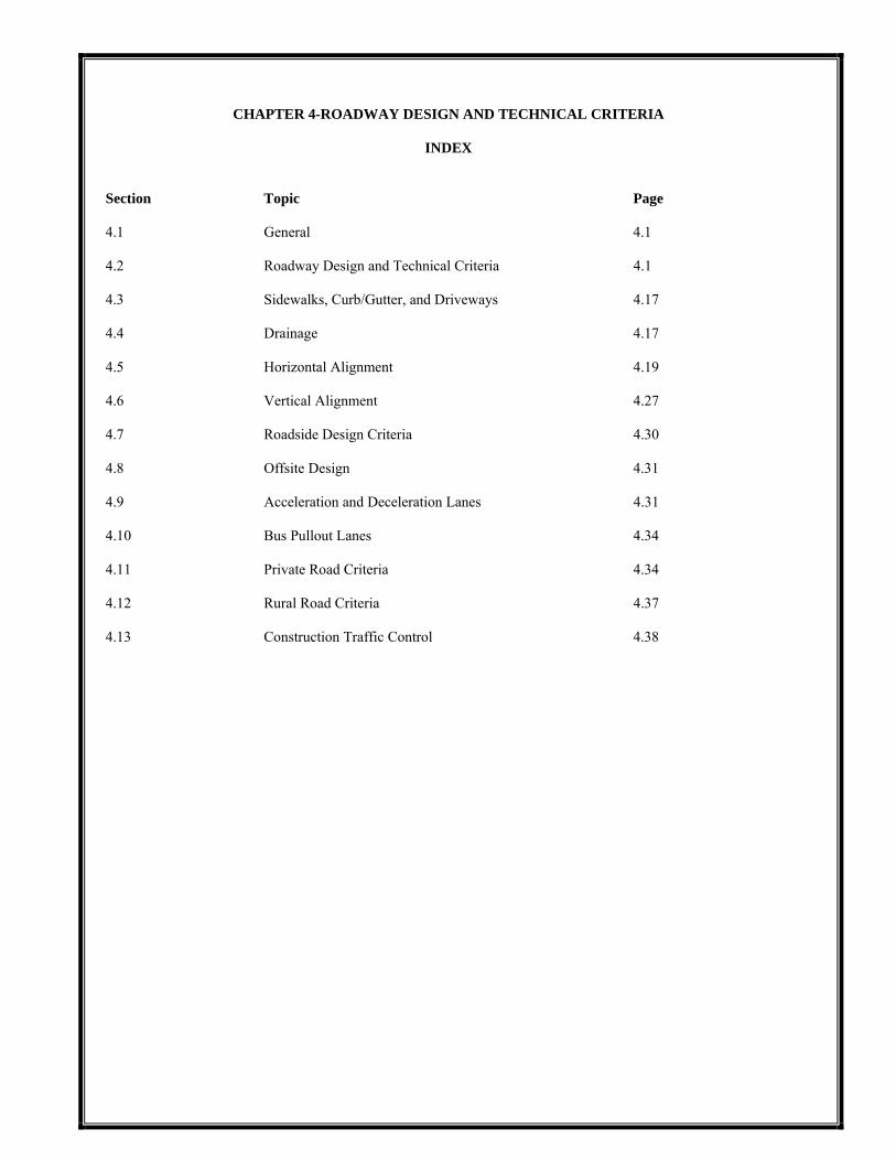
INDEX Section Topic Page 4.1 General 4.1 4.2 Roadway Design and Technical Criteria 4.1 4.3 Sidewalks, Curb/Gutter, and Driveways 4.17 4.4 Drainage 4.17 4.5 Horizontal Alignment 4.19 4.6 Vertical Alignment 4.27 4.7 Roadside Design Criteria 4.30 4.8 Offsite Design 4.31 4.9 Acceleration and Deceleration Lanes 4.31 4.10 Bus Pullout Lanes 4.34 4.11 Private Road Criteria 4.34 4.12 Rural Road Criteria 4.37 4.13 Construction Traffic Control 4.38
Revised 12/27/06 4-1
CHAPTER 4-ROADWAY DESIGN AND TECHNICAL CRITERIA 4.1 GENERAL
This section sets forth the minimum design, technical criteria and specifications to be used in the preparation of all roadway plans. 4.1.1 Within this chapter of the Roadway Design and Technical Criteria, AASHTO “Green Book” refers
to “A Policy on Geometric Design of Highways and Streets” most recent revision, as published by the American Association of State Highway and Transportation Officials.
4.2 ROADWAY DESIGN AND TECHNICAL CRITERIA
Arapahoe County has adopted a Functional Street Classification Plan based on traffic volumes, land use and expected growth. This Functional Street Classification Plan designates streets as local, collector (major and minor) and arterial (major and minor). The following criteria applies to each classification. Standard roadway cross sections are presented in Appendix A. 4.2.1 Planning Principles for Local Circulation Systems.
4.2.1.1 A local circulation system is a traffic management method, implemented to convey
vehicular, pedestrian and bicycle traffic through developed areas. Basic considerations in the design of local circulation systems must recognize the following factors:
4.2.1.1.1 Safety – for vehicular, pedestrian and bicycle traffic. 4.2.1.1.2 Efficiency of Service – for all users.
4.2.1.1.3 Livability – especially as affected by traffic elements in the circulation system.
4.2.1.1.4 Economy – These standards take economics into account while providing for
the safest roadway progression possible.
4.2.1.2 The following principles are an elaboration on one or more of these four factors. The principles are not intended as absolute criteria, since instances may occur where certain principles conflict. The principles should, therefore, be used as guidelines to proper circulation systems layout.
4.2.1.2.1 Ensure Vehicular, Pedestrian and Bicycle Access – The primary function
of a local street is to serve the abutting properties. Street widths, placement of sidewalks, patterns of streets and number of intersections are related to the safe and efficient access to abutting lands.
4.2.1.2.2 Minimize Through Trips – Through traffic on local and collector streets
increases the average speed and volume and thus the accident potential, thereby reducing residential amenities. Through traffic can be discouraged by creating a circuitous route between neighborhoods and higher volume streets and by channeling or controlling median crossings along peripheral routes.
4.2.1.2.3 Control Access to Arterials – Local circulation systems and land
development patterns should not detract from the efficiency of peripheral arterial facilities. Ideally, land development should occur so that no local streets require direct access to arterial routes. The number of access points between the local circulation system and arterial system should be minimized. Intersections along arterial routes should be properly spaced for
Revised 12/27/06 4-2
efficient signalization and traffic flow. The streets that do intersect the arterial system will tend to have higher volumes since they are the only exit points.
4.2.1.2.4 Discourage Speeding – Residential street should be designed to discourage
excessive speed (more than 25 m.p.h.). This can be accomplished through the use of curvilinear alignments and circuitous routes in the street system.
4.2.1.2.5 Minimize Pedestrian – Vehicular Conflicts – Pedestrian travel from
within the area to points outside should require a minimum number of street crossings. Sometimes this can be achieved through proper design of street patterns, land use arrangements and pedestrian routes. Typical methods include use of cul-de-sacs, loop streets, special pedestrian routes or walkways and the proper placement of high pedestrian traffic generators. In general, while vehicular flow must be outward oriented to the peripheral arterials, pedestrian travel should be inward-oriented to avoid these heavier vehicular flows.
4.2.1.2.6 Minimize Space Devoted to Street Use – It is desirable to minimize local
street mileage to reduce construction and maintenance costs as well as to permit the most economic land use. Streets should also have an appearance commensurate with their function. They should be in keeping with the residential character.
4.2.1.2.7 Relate Street to Topography – Local streets will be more attractive and
economical if they are constructed to closely adhere to existing topography. Using the existing topography of the area can enhance the important role that streets play in overall storm drainage system.
4.2.1.2.8 Layout Street to achieve Optimum Subdivision of Land – The
arrangement of streets should permit economical and practical patterns, shapes and sizes of development parcels. Streets, as a function of land use must not unduly hinder the development of land. Distances between streets, number of streets, and related elements all have a bearing on the efficiency of a subdivision. Access to adjoining properties should also be encouraged.
4.2.3 Urban Local
A local street is a general term denoting a residential roadway designed or operating with the following characteristics, No commercial property shall be permitted access to a local roadway:
A. POSTED SPEED LIMIT – 25 mph maximum per AASHTO “Green Book”.
Posted or Prima facie speeds for the various street classifications are normally 5-10 miles per hour less than the design speed of that street.
B. TRAFFIC VOLUMES – Less than 1,500 vehicles per day for residential
roadways with backing driveway access. Less than 2,500 vehicles per day for residential roadways with non-backing driveway access.
C. LIMITED CONTINUITY
D. SAFETY – Designed for the safety of pedestrians and bicyclists, and the ease of
access to adjacent parcels of land.
E. TRAFFIC CONTROL – Stop signs, yield signs, or right-of-way rules for uncontrolled intersections.
Revised 12/27/06 4-3
F. FUNCTION – Local streets provide direct access to adjacent property. Traffic carried by local streets should have an origin or a destination within the neighborhood. Utility line easements should be available.
G. RIGHT-OF-WAY – In single-family residential areas with monolithic rollover
curb, gutter and sidewalk: 50 feet minimum. In single-family residential with 5-foot detached sidewalk: 60 feet minimum. In multiple-family residential areas: 60 feet minimum.
H. NUMBER OF MOVING LANES – Two.
I. ACCESS CONDITIONS – Intersections at grade with direct access to abutting
property permitted.
J. PLANNING CHARACTERISTICS – Local streets should be designed to discourage through traffic from moving through the neighborhood. Local streets should not intersect major collectors or arterial streets. Single-Family Residential Local Roadways shall have either monolithic rollover curb, gutter and sidewalk or 5-foot detached sidewalk. Multi-family Residential Local Roadways shall have 5-foot detached sidewalk.
1. See section 11.2 for intersection spacing criteria.
K. TYPE OF CURB AND GUTTER – vertical, Hollywood type and high-speed
Type 2 (Sections IM and IIM as defined by CDOT M & S Standards) are permissible with attached sidewalk.
L. CUL-DE-SACS and KNUCKLES – Cul-de-sacs shall have a minimum flowline
radius of thirty-eight (38) feet, Knuckles shall have a minimum flowline radius of forty-five (45) feet (see detail SP-24). Cul-de-sacs may have a maximum length of 500 feet or a maximum of 15 dwelling units whichever is most restrictive. Extended lengths and/or increased number of dwelling units may be permitted only with written approval from the affected Fire Protection District and approval by the Board of County Commissioners.
O. MINIMUM LENGTH OF TANGENTS BETWEEN CURVES – (Reverse Curves Permissible) Minimum Tangent Length on Local Roadways shall be at least 25 feet.
P. MINIMUM LENGTH OF VERTICAL CURVES: See Table 4.6.
Q. STREET GRADES: A minimum longitudinal flowline grade of 1.0% shall be required on all Local streets except at curb returns, knuckles, and bubbles where the minimum flowline grade shall be 1.0%. Maximum grade shall be 7%. See table 4.1, table 4.6 and Section 4.4.2 (inlets).
Revised 12/27/06 4-4
R. CURB RADII – See table 4.3.
S. Maximum Tangent Length – ¼ Mile.
4.2.3 Collector
Minor Collector A minor collector is a general term denoting a roadway designed or operating with the following characteristics:
A. POSTED SPEED LIMIT – Between 25 and 35 mph. Posted or prima facie
speeds for the various street classifications are normally 5-10 miles per hour less than the design speed of that street.
B. TRAFFIC VOLUMES – Generally less than 7,000 vehicles per day.
C. CONTINUOUS – For less than 2 miles.
D. TRAFFIC VOLUMES – Designed to handle traffic volumes loading from and
onto local, other collector, and arterial roadways.
E. TRAFFIC CONTROL – on minor collectors provided by stop signs.
F. DRIVEWAYS – No back out drives permitted.
G. FUNCTION – Collector streets collect and distribute traffic between arterial and local streets and serve as main connectors within communities, linking one neighborhood with another. Traffic carried by minor collector streets should have an origin or a destination within the community. Utility easements should be available.
H. RIGHT-OF-WAY WIDTH – 76 feet minimum.
I. NUMBER OF MOVING LANES – Two.
J. ACCESS CONDITIONS – Intersections at grade with direct access to abutting
property permitted.
K. TRAFFIC CHARACTERISTICS – Regulation of traffic accomplished through the use of stop signs and channelization. Traffic signals normally used only at intersections with major collectors and arterial streets.
L. PLANNING CHARACTERISTICS –Minor Collector streets should have
continuity throughout a neighborhood but need not extend beyond the neighborhood. Intersections with minor collectors, major collectors and arterial streets should be at least one-quarter mile apart. Detached sidewalks are required with a 7 foot landscaped area separating the sidewalk and roadway.
M. TYPE OF CURB AND GUTTER – Vertical or high speed Type 2 (Sections IM
and IIM as defined by CDOT M & S Standards) permitted, detached sidewalk required.
N. STREET WIDTHS – 46’ paved with plus 2-2’ gutter pans (50’ flowline –
flowline).
Revised 12/27/06 4-5
O. MINIMUM RADIUS OF CURVATURE ON CENTER LINE (HORIZONTAL): See Table 4.2.
P. MINIMUM LENGTH OF TANGENTS BETWEEN CURVES – (Reverse
curves permissible) Minimum Tangent length shall be equal to or greater than the sum of the Superelevation Runoff Length and the Tangent Runout Length. See Section 4.5.5.3.
Q. MINIMUM LENGTH OF VERTICAL CURVES – See Table 4.6.
R. STREET GRADES – Minimum grade 1% - Maximum grade 6%.
S. CURB RADII – See Table 4.3.
4.2.3.2 Major Collector
A major collector is a general term denoting a roadway designed or operating with the following characteristics:
A. POSTED SPEED LIMIT – Between 30 and 45 mph. Posted or prima facie
speeds for the various street classifications are normally 5-10 miles per hour less than the design speed of that street.
B. TRAFFIC VOLUMES – Generally between 7,000 and 12,000 vehicles per day
when the land, which the collector serves, is fully developed.
C. CONTINUOUS – For 2 or more miles.
D. TRAFFIC VOLUMES – Designed to handle traffic volumes loading from and onto local, other collector and arterial roadways.
E. TRAFFIC CONTROL – Provided by traffic signals
F. DRIVEWAYS – No back-out drives permitted
G. FUNCTIONS – Major collector streets permit relatively unimpeded traffic
movement and are intended for use on those routes where four (4) moving lanes are required but where a larger classified street is not warranted.
H. RIGHT-OF-WAY – 88 feet.
I. NUMBER OF MOVING LANES – four.
J. ACCESS CONDITION:
1. Intersection at grade. 2. Intersection with other streets will not be restricted. 3. Access from street of lower classification will be permitted but in all cases
will be controlled by traffic-control devices when warrants are met. 4. Normally, all abutting property will be allowed access to the streets and will
face the street but perhaps with increased setback requirements.
K. TRAFFIC CHARACTERISTICS 1. Regulation of traffic accomplished by signs and channelization. 2. Traffic signals will normally be located only at intersection with streets of
equal or higher classification. 3. Parking shall be prohibited.
Revised 12/27/06 4-6
L. PLANNING CHARACTERISTICS 1. Major collector streets should be employed where traffic demands are high
and right-of-way acquisition costs are not prohibitive. 2. Detached sidewalk required except at intersections. See Roadway Cross
Section for Major Collector at Intersection in the appendix. 3. Design elements (Trees, open space, etc.) are recommended.
M. TYPE OF CURB AND GUTTER – Vertical or High speed Type 2 (Sections IM
and IIM as defined by CDOT M & S Standards), detached sidewalk required except at intersections where attached walk is permitted. High speed Type 2 (Sections IM and IIM as defined by CDOT M & S Standards) Curb is required for all roadways with a posted speed of 45 miles per hour and above.
N. STREET WIDTHS – There are two types of Major Collectors one at
intersections and one when between intersections. The street widths are as follows for each options: 1. At Intersections – 4-12’ travel lanes; 1-14 center median; 2-2’ gutter pans;
2-5’ bike lanes (76’ flowline – flowline). 2. Between Intersections – 4-12’ travel lanes, 2-2’gutter pans and 2-5’ bike
lanes (62’ flowline – flowline).
O. MINIMUM RADIUS OF CURVATURE ON CENTER LINE (HORIZONTAL); See Table 4.2.
P. MINIMUM LENGTH OF TANGENTS BETWEEN CURVES – Minimum
Tangent length shall be equal to or greater than the sum of the Superelevation Runoff Length and the Tangent Runout Length. See Section 4.5.5.1
Q. MINIMUM LENGTH OF VERTICAL CURVES. See Table 4.6.
R. STREET GRADES – Minimum grade 1% maximum grade 6%.
S. CURB RADII – See Table 4.3.
4.2.4 Arterial
4.2.4.1 Minor Arterial An arterial street is a general term denoting a roadway designed or operating with the following characteristics:
A. POSTED SPEED LIMIT – Greater than or equal to 35 mph. Posted or prima
facie speeds for the various street classifications are normally 5-10 miles per hour less than the design speed of that street.
B. WIDTH – 4-lane minimum width, plus additional auxiliary lanes.
C. TRAFFIC VOLUMES – 12,000 TO 20,000 vehicles per day expected traffic
volume when the land, which the arterial serves, is fully developed.
D. ACCESS – Limited access to adjacent parcels of land.
E. CONTINUITY – Several miles, generally connecting with intercity routes.
F. TRAFFIC CONTROL – On arterial provided by traffic signals.
Revised 12/27/06 4-7
G. FUNCTION – Arterial routes permit relatively unimpeded traffic movement and are intended for use on these routes where four moving lanes and one left-turn lane are required but where a major arterial cross section would not be warranted.
H. RIGHT-OF-WAY WIDTH – 114 feet minimum.
I. NUMBER OF MOVING LANES – Four.
J. ACCESS CONDITIONS – Intersection at grade. Intersection with other streets
will not be restricted. Access from street of lower classification will be permitted but in all cases will be controlled by traffic control devices. Normally, all abutting property will be allowed access to the street if no other access is available and will face the street but perhaps with increased setback requirements.
K. TRAFFIC CHARACTERISTICS – Regulation of traffic accomplished by signs
and channelization. Traffic signals will normally be located only at intersections with streets of equal or higher classification. Parking shall be prohibited.
L. PLANNING CHARACTERISTICS – Arterial should be spaced from ½ to 1
mile apart and should, where possible, be continuous. Arterial should act as boundaries between neighborhood areas. Arterial cross section should be employed where traffic demands are high and right-of-way acquisition costs are not prohibitive. Detached sidewalk required. Separate major land uses.
M. TYPE OF CURB AND GUTTER – Vertical or High speed Type 2 (Sections IM
and IIM as defined by CDOT M & S Standards), detached 8’ sidewalk required. High speed Type 2 (Sections IM and IIM as defined by CDOT M & S Standards) Curb is required for all roadways with a posted speed of 45 miles per hour and above.
N. STREET WIDTHS – 4-12’ travel lanes; 1-16’ left turn lane/striped median; 2-2’
gutter pans 2-5’ bike lanes plus acceleration/deceleration lanes at intersections (78’ flowline – flowline).
O. MINIMUM RADIUS OF CURVATURE ON CENTER LINE
(HORIZONTAL); See Table 4.2.
P. MINIMUM LENGTH OF TANGENTS BETWEEN CURVES – Minimum Tangent length shall be equal to or greater than the sum of the Superelevation Runoff Length and the Tangent Runout Length. See Section 4.5.5.1.
Q. MINIMUM LENGTH OF VERTICAL CURVES – See Table 4.6.
R. STREET GRADES – Minimum grade 1% maximum grade 6%.
S. CURB RADII- See Table 4.3.
4.2.4.2 Major Arterial (4 Lane)
A. POSTED SPEED LIMIT – Greater than or equal to 35 mph. Posted or prima
facie speeds for the various street classifications are normally 5-10 miles per hour less than the design speed of that street.
B. WIDTH – 4-lane minimum width, plus additional turn lanes.
Revised 12/27/06 4-8
C. TRAFFIC VOLUMES – 12,000 to 30,000 vehicles per day expected traffic
volume when the land, which the arterial serves, is fully developed.
D. ACCESS – Limited access to adjacent parcels of land.
E. CONTINUITY – Several miles, generally connecting with intercity routes.
F. TRAFFIC CONTROL – On arterial provided by traffic signals.
G. FUNCTION – Major arterial streets permit rapid and relatively unimpeded traffic movement through the county, connecting major land use elements as well as communities with one another.
H. RIGHT-OF-WAY WIDTH –114’ minimum.
I. NUMBER OF MOVING LANES – Four.
J. ACCESS CONDITIONS – Intersections will generally be at grade.
Intersections will normally be located at one-quarter mile intervals. Traffic control devices shall control access from collector and arterial streets. Normally, abutting properties and local streets will not be allowed direct access to the street. Abutting properties should not face on the roadway unless separated from it by a frontage road.
K. TRAFFIC CHARACTERISTICS – Movement of traffic will be controlled by
signals and channelization. Parking shall be prohibited. Roadway should have a median strip between them.
L. PLANNING CHARACTERISTICS – Major arterial streets should be spaced
approximately one mile apart and should traverse the entire city and/or county. Major arterial streets should not bisect neighborhoods but should act as boundaries between them. Detached sidewalk required.
M. TYPE OF CURB AND GUTTER – Vertical or High speed Type 2 (Sections IM
and IIM as defined by CDOT M & S Standards), detached 8’ sidewalk required. High speed Type 2 (Sections IM and IIM as defined by CDOT M & S Standards) Curb is required for all roadways with a posted speed of 45 miles per hour and above.
N. STREET WIDTHS – 4-12’ travel lanes; 14’ medians; 2-1’ median gutter pans,
2-2’ gutter pans 2-5’ bike lanes plus necessary left turn and acceleration/deceleration lanes and 4’ median at intersections (78’ flowline – flowline).
O. MINIMUM RADIUS OF CURVATURE ON CENTER LINE
(HORIZONTAL); See Table 4.2.
P. MINIMUM LENGTH OF TANGENTS BETWEEN CURVES – Minimum Tangent length shall be equal to or greater than the sum of the Superelevation Runoff Length and the Tangent Runout Length. See Section 4.5.5.1.
Q. MINIMUM LENGTH OF VERTICAL CURVES. See Table 4.6.
R. STREET GRADES – Minimum grade 1% maximum grade 6%.
Revised 12/27/06 4-9
S. CURB RADII – See Table 4.3.
4.2.4.3 Major Arterial (6 Lane)
A. POSTED SPEED LIMIT – Greater than or equal to 35 mph. Posted or prima facie speeds for the various street classifications are normally 5-10 miles per hour less than the design speed of that street.
B. WIDTH – 6-lane minimum width, plus additional turn lanes.
C. TRAFFIC VOLUMES – 12,000 to 45,000 vehicles per day expected traffic
volume when the land, which the arterial serves, is fully developed.
D. ACCESS – Limited access to adjacent parcels of land.
E. CONTINUITY – Several miles, generally connecting with intercity routes.
F. TRAFFIC CONTROL – On arterial provided by traffic signals.
G. FUNCTION – Major arterial streets permit rapid and relatively unimpeded traffic movement throughout the county, connecting major land use elements as well as communities with one another.
H. RIGHT-OF-WAY WIDTH – 144’ minimum.
I. NUMBER OF MOVING LANES – Six.
J. ACCESS CONDITIONS – Intersections will generally be at grade.
Intersections will normally be located at one-quarter mile intervals. Access from collector and arterial streets shall be controlled by traffic control devices. Normally, abutting properties and local streets will not be allowed direct access to the street. Abutting properties should not face on the roadway unless separated from it by a frontage road.
K. TRAFFIC CHARACTERISTICS – Movement of traffic will be controlled by
signals and channelization. Parking shall be prohibited. Roadways should have a median strip between them.
L. PLANNING CHARACTERISTICS – Major arterial streets should be spaced
approximately one mile apart and should traverse the entire city and/or county. Major arterial streets should not bisect neighborhoods but should act as boundaries between them. Detached sidewalk required.
M. TYPE OF CURB AND GUTTER – Vertical or High speed Type 2 (Sections IM
and IIM as defined by CDOT M & S Standards), detached 10’ sidewalk required. High speed Type 2 (Sections IM and IIM as defined by CDOT M & S Standards) Curb is required for all roadways with a posted speed of 45 miles per hour and above.
N. STREET WIDTHS – 6-12’ travel lanes; 26’ medians; 2-1’ median gutter pans,
2-2’ gutter pans, plus necessary left turn and acceleration/deceleration lanes and 4’ minimum median at intersections (104’ flowline – flowline).
O. MINIMUM RADIUS OF CURVATURE ON CENTER LINE
(HORIZONTAL); See Table 4.2.
Revised 12/27/06 4-10
P. MINIMUM LENGTH OF TANGENTS BETWEEN CURVES – Minimum Tangent length shall be equal to or greater than the sum of the Superelevation Runoff Length and the Tangent Runout Length. See Section 4.5.5.1.
Q. MINIMUM LENGTH OF VERTICAL CURVES. See Table 4.6.
R. STREET GRADES – Minimum grade 1% maximum grade 6%.
S. CURB RADII – See Table 4.3.
4.2.4.4 Urban Expressway (8 Lanes)
A. POSTED SPEED LIMIT – Greater than or equal to 35 mph. Posted or prima
facie speeds for the various street classifications are normally 5-10 miles per hour less than the design speed of that street.
B. WIDTH – 8-lane minimum width, plus additional turn lanes.
C. TRAFFIC VOLUMES – 45,000 vehicles per day expected minimum traffic
volume when the land, which the expressway serves, is fully developed.
D. ACCESS – Limited access to adjacent parcels of land.
E. CONTINUITY – Several miles, generally connecting with intercity routes.
F. TRAFFIC CONTROL – On expressway provided traffic signals.
G. FUNCTION – Expressway streets permit rapid and relatively unimpeded traffic movement throughout the county, connecting major land use elements as well as communities with one another.
H. RIGHT-OF-WAY WIDTH – 168’ minimum.
I. NUMBER OF MOVING LANES – Eight.
J. ACCESS CONDITIONS –ACCESS CONDITIONS – Intersections will either
be at grade or grade-separated dependant on traffic volumes. Intersections will normally be located at one-mile intervals. Access from arterial streets shall be controlled by traffic control devices or grade separated interchanges. Abutting properties should not face on the roadway unless separated from it by a frontage road.
K. TRAFFIC CHARACTERISTICS – Movement of traffic will be controlled by
signals and channelization. Parking shall be prohibited. Roadways should have a median strip between them.
L. PLANNING CHARACTERISTICS – Expressway streets should only be
utilized when traffic projections provide necessity and should traverse the entire city and/or county. Expressway streets should not bisect neighborhoods and should only be accessed by Arterial roadways. Detached sidewalk required.
M. TYPE OF CURB AND GUTTER – High speed Type 2 (Sections IM and IIM as
defined by CDOT M & S Standards), detached 10’ sidewalk required.
Revised 12/27/06 4-11
N. STREET WIDTHS – 8-12’ travel lanes; 26’ raised median; 2-1 median gutter pans, 2-2’ gutter pans plus necessary left turn and acceleration/deceleration lanes and 4’ minimum median at intersections (128’ flowline – flowline).
O. MINIMUM RADIUS OF CURVATURE ON CENTER LINE
(HORIZONTAL); See Table 4.2.
P. MINIMUM LENGTH OF TANGENTS BETWEEN CURVES – Minimum Tangent length shall be equal to or greater than the sum of the Superelevation Runoff Length and the Tangent Runout Length. See Section 4.5.5.1.
Q. MINIMUM LENGTH OF VERTICAL CURVES. See Table 4.6.
R. STREET GRADES – Minimum grade 1% maximum grade 6%.
S. CURB RADII – See Table 4.3.
4.2.5 Freeways
Freeways are designed and built to provide inter-city, inter-county, and/or interstate traffic flow. They are controlled access roadways. All Freeway and Interstate Improvements are under the jurisdictional authority of the State of Colorado. Proposed Improvements shall not be approved by Arapahoe County.
A. FUNCTION – Freeways permit rapid and unimpeded movement of traffic
through and around the County.
B. RIGHT-OF-WAY WIDTH – 300 feet minimum.
C. NUMBER OF MOVING LANES – Four to ten.
D. ACCESS CONDITIONS – Access will be completely controlled. No intersections at grade will be permitted.
E. TRAFFIC CHARACTERISTICS – No traffic signals. Parking prohibited.
Roadways will be divided.
F. PLANNING CHARACTERISTICS –Freeways should connect with main highways approaching and leaving the county from all directions. Freeways should be so aligned as to serve the major traffic generators within the county. (Major business district, major industrial areas, regional shopping centers, etc.) Freeways should not bisect neighborhoods or communities but should act as boundaries between them.
G. DESIGN CRITERIA – To be developed on a case-by-case basis but generally
conforming to CDOT standards and criteria.
4.2.6 Rural Primary (4-Lane)
A. POSTED SPEED LIMIT – Greater than or equal to 35 mph. Posted or prima facie speeds for the various street classifications are normally 5-10 miles per hour less than the design speed of that street.
B. WIDTH – 2-lane minimum width with expansion capability to 4-lanes, plus
additional turn lanes.
Revised 12/27/06 4-12
C. TRAFFIC VOLUMES – Generally between 10,000 and 20,000 vehicles per day when the land in which the roadway serves is being fully developed.
D. ACCESS- Limited access to adjacent parcels of land.
E. CONTINUITY – Several miles, generally connecting rural towns.
F. TRAFFIC CONTROL – On Rural Primary provided by traffic signals and/or
signs.
G. FUNCTION – Rural Primary Roads permit relatively unimpeded traffic movement throughout the rural portion of the County.
H. RIGHT-OF-WAY WIDTH – 114’ minimum.
I. NUMBER OF MOVING LANES- four.
J. ACCESS CONDITIONS – Intersections will generally be at grade.
Intersections will normally be located at one-quarter mile intervals. Abutting properties, collector and local streets shall normally be allowed acceptable access to the street.
K. TRAFFIC CHARACTERISTICS – Movement of traffic will be controlled by
signals and channelization. Parking shall be prohibited.
L. PLANNING CHARACTERISTICS – Rural Primary Roads should be utilized along section lines and where traffic projections warrant the additional lanage and right-of-way.
M. STREET WIDTHS – 4-12’ travel lanes; 2-6’ shoulders plus necessary left turn
and acceleration/deceleration lanes and variable width drainage ditch area (60’ Edge of Shoulder – Edge of Shoulder).
N. MINIMUM RADIUS OF CURVATURE ON CENTER LINE
(HORIZONTAL); See Table 4.2.
O. MINIMUM LENGTH OF TANGENTS BETWEEN CURVES- Minimum Tangent length shall be equal to or greater than the sum of the Superelevation Runoff Length and the Tangent Runout Length. See Section 4.5.5.1.
P. MINIMUM LENGTH OF VERTICAL CURVES. See Table 4.6.
Q. STREET GRADES – Minimum grade 1% maximum grade 6%.
R. CURB RADII – See Table 4.3.
4.2.7 Rural Secondary (2-Lane)
A. POSTED SPEED LIMIT – Greater than or equal to 35 mph. Posted or prima
facie speeds for the various street classifications are normally 5-10 miles per hour less than the design speed of that street.
B. WIDTH – 2-lane width, plus additional turn lanes.
C. TRAFFIC VOLUMES – Generally between 7,000 and 10,000 vehicles per day
when the land in which the roadway serves is fully developed.
Revised 12/27/06 4-13
D. ACCESS – Direct access to adjacent parcels of land.
E. CONTINUITY – Generally less than 2 miles, generally connecting Rural
Primary Roads.
F. TRAFFIC CONTROL – On Rural Secondary provided by traffic control signs.
G. FUNCTION – Rural Secondary Roads collect and distribute traffic between Rural Primary Roads and Rural Local Roads.
H. RIGHT-OF-WAY WIDTH – 60’ minimum (Must be wide enough to
accommodate roadside drainage requirements).
I. NUMBER OF MOVING LANES – two.
J. ACCESS CONDITIONS – Intersections will generally be at grade. Abutting properties and rural local streets will normally be allowed acceptable access to the street.
K. TRAFFIC CHARACTERISTICS – Movement of traffic will be controlled by
signage. Parking shall be prohibited.
L. PLANNING CHARACTERISTICS – Rural Secondary Roads should be utilized as collector roadways for distribution of Rural Primary Road traffic.
M. STREET WIDTHS – 2-14’ travel lanes; 2-6’ shoulders plus necessary left turn
and acceleration/deceleration lanes and variable width drainage ditch area (40’ Edge of Shoulder – Edge of Shoulder).
N. MINIMUM LENGTH OF VERTICAL CURVES. See Table 4.6.
O. MINIMUM LENGTH OF TANGENTS BETWEEN CURVES – Minimum
Tangent length shall be equal to or greater than the sum of the Superelevation Runoff Length and the Tangent Runout Length. See Section 4.5.5.1.
P. MINIMUM LENGTH OF VERTICAL CURVES. See Table 4.6.
Q. STREET GRADES – Minimum grade 1% maximum grade 6%.
R. CURB RADII – See Table 4.3.
4.2.8 Rural Local (2-Lane)
A. POSTED SPEED LIMIT – Greater than or equal to 25 mph. Posted or prima
facie speeds for the various street classifications are normally 5-10 miles per hour less than the design speed of that street.
B. WIDTH – 2-lane width, plus additional turn lanes.
C. TRAFFIC VOLUMES – Generally less than 1,500 vehicles per day when the
land in which the roadway serves is fully developed.
D. ACCESS – Direct access to adjacent parcels of land.
E. LIMITED CONTINUITY.
Revised 12/27/06 4-14
F. TRAFFIC CONTROL – On Rural Local provided by traffic signs.
G. FUNCTION – Traffic carried by Rural Local Streets should have an origin or
destination within the neighborhood.
H. RIGHT-OF-WAY WIDTH – 50’ minimum (Must be wide enough to accommodate roadside drainage requirements).
I. NUMBER OF MOVING LANES – two.
J. ACCESS CONDITIONS – Intersections will generally be at grade. Abutting
properties shall normally be allowed acceptable access to the street.
K. TRAFFIC CHARACTERISTICS – Movement of traffic will be controlled by traffic control signs. Parking shall be prohibited.
L. PLANNING CHARACTERISTICS – Rural Local Roads should be designed to
discourage through traffic. Access to rural primary roads is discouraged.
M. STREET WIDTHS – 2-14’ travel lanes; 2-6’ shoulders plus necessary left turn and acceleration/deceleration lanes and variable width drainage ditch area (40’ flowline – flowline).
N. MINIMUM RADIUS OF CURVATURE ON CENTER LINE
(HORIZONTAL); See Table 4.2.
O. MINIMUM LENGTH OF TANGENTS BETWEEN CURVES- Minimum Tangent length shall be equal to or greater than the sum of the Superelevation Runoff Length and the Tangent Runout Length. See Section 4.5.5.1.
P. MINIMUM LENGTH OF VERTICAL CURVES. See Table 4.6.
Q. STREET GRADES – Minimum grade 1% maximum grade 6%.
R. CURB RADII – See Table 4.3.
4.2.9 Roadway Specifications
Table 4.1 shows a summary of the minimum roadway construction requirements and other related information.
LOCAL URBAN EXPRESSWAYMINOR MAJOR MINOR MAJOR 4-LANE MAJOR 6-LANE
DESIGN SPEED 30-35 30-35 40 45 55 55 55DRIVING LANES 2 2 4 4 4 6 8MINIMUM R.O.W. 50' 76' 88' 114' 114' 144' 168'ROADWAY WIDTH AND 34' 50' 62' 78' 78' 104' 128'COMPOSITION OF 30' PAVED WIDTH 46' Paved 58' paved 74' paved 74' paved 100' paved 124' pavedCROSS SECTION AT 2-2' GUTTER PANS 2-2' gutter pans 2-2' gutter pans 2-2' gutter pans 2-2' gutter pans 2-2' gutter pans 2-2' gutter pansINTERSECTIONROADWAY WIDTH AND SAME SAME 76' SAME SAME SAMECOMPOSITION OF 72' pavedCROSS SECTION NOT 2-2' gutter pansAT INTERSECTIONSIDEWALK, CURB COMBINATION, VERTICAL OR VERTICAL OR VERTICAL OR VERTICAL OR VERTICAL OR VERTICAL ORGUTTER VERTICAL OR HIGH SPEED TYPE 2 HIGH SPEED TYPE 2 HIGH SPEED TYPE 2 HIGH SPEED TYPE 2 HIGH SPEED TYPE 2 HIGH SPEED TYPE 2
HIGH SPEED TYPE 2 DETACHED 6' WALK DETACHED 6' WALK DETACHED 8' WALK DETACHED 8' WALK DETACHED 10' WALK DETACHED 10' WALKCURB RETURN MINIMUMRADII-INTERSECT ARTERIAL - 40' 40' 50' 50' 50' 50'-INTERSECT COLLECTOR 30' 40' 40' 40' 40' 40' --INTERSECT LOCAL 20' 30' - - - - -MINIMUM RADIUS ATCURVE AT CENTERLINE 100-300' 300-475 700 900PER AASHTOMIN TANGENT LENGTH Min. 25 Min. 90-105 Min. 120 Min. 132BETWEEN REVERSE CURVESMAXIMUM GRADE OFINTERSECTION-INTERSECT ARTERIAL - 1%-3% 1%-3% 1%-2% 1%-2% 1-2% 1-2%-INTERSECT COLLECTOR 1%-4% 1%-3% 1%-3% 1%-3% 1%-3% 1%-3% --INTERSECT LOCAL 1%-4% 1%-4% 1%-4% - - - -MIN-MAX STREET 1%-7% 1%-6% 1%-6% 1%-6% 1%-6% 1%-6% 1%-5%GRADIENTVERTICAL ALIGNMENT CONTROLMINIMUM PAVEMENTSECTION
COLLECTOR ARTERIALTable 4.1 ROADWAY CONSTRUCTION STANDARDS
Super Elevation is required see section 4.5.5
See Table 5.4
Equals the Super Elevation Runoff Length + Tangent Runout Length
See Table 4.6
Equals the Super Elevation Runoff Length + Tangent Runout Length
Revised 12/27/06 4-16
RURAL LOCALSECONDARY PRIMARY
DESIGN SPEED 35 50 60DRIVING LANES 2 2 4MINIMUM R.O.W. 50' 60' 114'ROADWAY WIDTH AND 40' 40' 60'COMPOSITION OF 28' Paved 28' Paved 48' pavedCROSS SECTION AT 2-6' Gravel Shoulders 2-6' Gravel Shoulders 2-6' Gravel ShouldersINTERSECTIONROADWAY WIDTH AND SAME SAME SAMECOMPOSITION OF CROSS SECTION NOT AT INTERSECTIONSIDEWALK, CURB Normally Normally NormallyGUTTER no Curb & Gutter no Curb & Gutter no Curb & Gutter
or Sidewalk or Sidewalk or SidewalkCURB RETURN MINIMUMRADII-INTERSECT ARTERIAL EOA Return EOA Return EOA Return-INTERSECT COLLECTOR same as same as same as -INTERSECT LOCAL Table 4.1 Table 4.2 Table 4.3MINIMUM RADIUS ATCURVE AT CENTERLINE 100-300' See Table 4.2 See Table 4.2PER AASHTOMIN TANGENT LENGTH 25 90-105 120BETWEEN REVERSE CURVESMAXIMUM GRADE OFINTERSECTION-INTERSECT ARTERIAL-INTERSECT COLLECTOR-INTERSECT LOCALMIN-MAX STREET 1%-7% 1%-6% 1%-6%GRADIENT 7% in Mountainous 7% in Mountainous
Terrain TerrainVERTICAL ALIGNMENT See Table 4.6 See Table 4.6 See Table 4.6CONTROLMINIMUM PAVEMENT As Defined by As Defined by As Defined bySECTION Pavement Design Pavement Design Pavement Design
Report Report Report
TABLE 4.1 ROADWAY CONSTRUCTION STANDARDS CONT.
1-3% desirable
RURAL COLLECTOR
Revised 12/27/06 4-17
4.3 SIDEWALKS, CURB/GUTTER, AND DRIVEWAYS 4.3.1 Roadway typical sections shall be as specified by these Standards. Details are located in
Appendix A of these Standards.
4.3.2 Sidewalks or bicycle paths shall be constructed on both sides of all urban roadways unless specifically deleted by action of the Board of County Commissioners.
4.3.3 All sidewalks used in conjunction with vertical or high-speed Type 2 (Sections IM and IIM as defined by CDOT M & S Standards) curb and gutter shall have a minimum width of five feet.
4.3.4 Combination curb, gutter and walk is approved for use on local roadways only. Vertical or high-speed Type 2 (Sections IM and IIM as defined by CDOT M & S Standards) curb, gutter and detached walk shall be used on all other roadways.
4.3.5 State law requires that handicap ramps be installed at all intersections and at certain mid-block locations for all new construction or reconstruction of curb and sidewalks. (CRS 42-2-107 {2}. Handicap ramps shall be constructed in accordance with the Arapahoe County Standards Details found in Appendix A of these Standards or the Americans with Disabilities Act Standards (most recent revision) whichever is more restrictive. Handicap ramps may be shown at all curb returns or called out by a general note on the development plans, but must be shown (located) at all “T” intersections. Whenever referencing a handicap ramp call out the specific Arapahoe County Standard Detail to be used to construct that ramp.
4.3.6 Curb cuts are allowed for commercial/industrial or high volume residential driveways. In general,
when the number of parking spaces serviced by the driveway exceeds ten (10), radius returns are required (See Table 4.3 for flowline radius).
4.3.7 Where curb cuts are allowed based on traffic considerations, concentrated storm water runoff must
not be discharged across the sidewalk. The Design Engineer is responsible for determining acceptable alternatives to convey flows. Sidewalk Chases will be strongly discouraged in new developments and will only be permitted as a Final Alternative. (See Section 4.4.6). If this is not possible due to grading restraints, radius returns and a crosspan must be used.
4.3.8 Curb cuts and driveways shall be constructed in accordance with the Arapahoe County Standard Detail Sp. 6 found in Appendix A of these Standards.
4.4 DRAINAGE
The minor and major storm drainage systems are designed in accordance with the Arapahoe County Storm Drainage Criteria Manual. Because safe and efficient conveyance of traffic is the primary function of roadways, the storm drainage function of the roadway (such as allowable gutter capacity and street overtopping) will be designed to the limits set forth in the Manual. In the case of conflict caused by requirements of the Manual, drainage requirements shall govern.
4.4.1 Crosspans
Crosspans shall be constructed in accordance with the Arapahoe County Standard Details (SP-7, in Appendix A). Crosspans are not permitted across collector or arterial roadways, nor are they allowed on roadways with storm sewer systems. Crosspans shall be a minimum of 8-feet wide, additional width may be required to accommodate drainage flows.
Double crosspans (crosspan on both sides of major roadway running parallel to one another) may be used parallel to collector or arterial roadways to convey storm runoff across residential roadways. The use of double crosspans elsewhere, or the use of any crosspan on roadways where
Revised 12/27/06 4-18
the vertical grade exceeds four and one-half (4.5) percent at the crosspan will be considered only after all other alternatives have been exhausted.
4.4.2 Inlets
Inlets shall be located to intercept the curb flow at the point curb flow capacity is exceeded by the storm runoff. Refer to Chapter 9 in the Manual for curb capacity. Inlets shall also be installed to intercept cross-pavement flows at points of transition in superelevation. Due to the presence of handicap ramps, inlets are not allowed in the curb return, but will be located at the tangent points of the curb returns.
4.4.3 Cross Slope
Except at intersections, or where superelevation is required, roadways shall be level from top of curb to top of curb (or flowline to flowline) and shall have a two (2) percent crown. At or within 150’ of an intersection, the maximum elevation difference between flowlines is that dictated by the allowable intersection grade (Figure 4.3) and the actual distance between flowlines.
4.4.3.1 Parabolic or curved crowns are not allowed. In no case shall the pavement cross slope at warped intersections exceed the grade of the through street.
4.4.3.2 The rate of change in pavement cross slope, when warping side streets at intersections,
shall not exceed one (1) percent every twenty-five (25) feet horizontally on a local roadway, one (1) percent every thirty-seven and one-half (37.5) feet horizontally on a collector roadway, or one (1) percent every fifty-six and one-half (56.5) feet horizontally on arterial roadways. See Section 4.6.6 of these standards.
4.4.4 Temporary Erosion Control
Temporary erosion control is required along and at the ends of all roadways that are not completed due to project phasing, subdivision boundaries, etc., in accordance with the Manual, Chapter 14, the Arapahoe County Grading, Erosion and Sediment Control (GESC) Manual and other approved Public Works and Development Administrative Procedures.
4.4.5 Permanent Erosion Control
Permanent Erosion Control is required for all new site development as well as redevelopment. All Permanent Erosion Control measures shall be performed in accordance with the Manual and the Arapahoe County Grading, Erosion and Sediment Control Manual (GESC).
4.4.6 Sidewalk Chases
Where curb cuts are allowed based on traffic considerations, concentrated storm water runoff must not be discharged across the sidewalk. The Design Engineer is responsible for determining acceptable alternatives to convey flows. Sidewalk Chases will be strongly discouraged in new developments and will only be permitted as a Final Alternative through the variance process (See Section 3.2). If this is not possible due to grading restraints, radius returns and a crosspan must be used. In the event a chase section is approved, the chase sections shall not be located within the curb cut or driveway. A hydraulic design shall be in required in accordance with the Manual. Approved Sidewalk chase sections are to be constructed in accordance with the Arapahoe County Standard Details found in Appendix A of these Standards.
∗ Superelevation required at design speed 45 mph and up ∗ All design calculations for superelevation shall be submitted along with plan and profile
4.5.2 Curb Return Radius
Minimum return radius shall be shown in Table 4.3 below.
TABLE 4.3 CURB RETURN RADII
AT 90º INTERSECTIONS (MEASURED ALONG FLOWLINE)
4.5.3 Design Speed
Horizontal alignment design speed shall be consistent with the requirement for vertical alignment design speed. If no superelevation is required and a normal crown section exists, the horizontal curve data, up to 40 mph, as shown in Table 4.2 shall be considered.
4.5.4 Barricades
Whenever roadways terminate due to project phasing, subdivision boundaries, etc., barricades are required. Design and construction shall comply with the requirements of the Manual of Uniform
INTERSECTING STREETS THROUGH STREET ARTERIAL COLLECTOR LOCAL
SERVICE ARTERIAL 50’ 40’ NOT
PERMITTED COLLECTOR 40’ 40’ *30’
LOCAL SERVICE
NOT PERMITTED
30’ *20’
* NO PARKING IS ALLOWED WITHIN 30-FEET OF PCR ON APPROACHES TO ALL CONTROLLED INTERSECTIONS. ALL OTHER APPROACHES AND DEPARTURES
SHALL HAVE NO PARKING OR DRIVEWAY ACCESS WITHIN 20-FEET OF THE PCR,
Revised 12/27/06 4-20
Traffic Control Devices most recent edition. Details shall be shown on the construction drawings, and installation shall be provided by the developer.
4.5.5 Superelevation
Superelevation is required for curves on all roadway classifications of arterial designation or higher and for selected collector roadways that will require superelevation to function properly. Horizontal curve radius and superelevation shall be in accordance with the requirements detailed within this manual and the recommendations of all supporting references.
The use of Superelevation shall be avoided on all roadways with a design speed of 40 mph or less. If superelevation cannot be avoided on a roadway with a design speed of 40 mph or less all design criteria within these standards and recommendations of the AASHTO “Green Book” shall apply.
The use of Superelevation on County roadways with a design speed greater than 40 mph shall be designed in conformance with these standards and recommendations of the AASHTO “Green Book” shall apply.
The following procedure is an outline for the correct application of superelevation on roadways within Arapahoe County.
4.5.5.1 Definitions Regarding Superelevation
Superelevation Runoff – That length of roadway needed to accomplish the change in cross slope from a section with the adverse crown removed (flat) to the fully superelevated section, or vice versa.
Transition Points – Beginning or ending of tangent runout, superelevation runoff of full superelevation.
Tangent Runout – That length of roadway needed to accomplish the change in cross slope from a normal (2.0%) crown section with the adverse crown removed (flat), or vice versa.
4.5.5.2 General
One of the most important factors to consider in highway safety is the centrifugal force generated when a vehicle traverses a curve. Centrifugal force increases as the velocity of the vehicle and/or the degree of curvature increases.
In order to overcome the effects of centrifugal force, all curves must be superelevated. It is impossible to balance centrifugal force by superelevation alone, because for any given curve radius a certain superelevation rate is exactly correct for only one driving speed. At all other speeds there will be a side thrust either outward or inward, relative to the curve, which must be offset by side friction.
From the Law of Mechanics the basic formula that governs vehicular operation on a curve is:
R
VR
VgRV
effe
15
067.0
01.01
01.0 222
===+
+
e = Rate of Superelevation f = Side Friction Factor V = Velocity in MPH R = Horizontal Curve Radius g = Gravity
Revised 12/27/06 4-21
The Standard Equation used to determine Side Friction Factors is:
eR
Vf 01.015
2
−=
The following table lists the acceptable friction factors on Low Speed Urban Roadways for superelevation design:
The minimum radius for a given speed, rate of superelevation and side friction factor is:
( )efVR
01.015
2
min +=
4.5.5.3 Standards for Superelevation on State Roadways
CDOT’S M & S (“M” Standards) on Superelevation shall be used to determine the required rate of Superelevation for all state jurisdictional roadways.
The Division “M” Standards include tables that detail the required rate of Superelevation for various degrees of curvature along the horizontal curve. The applicable tables within the Division “M” Standards are as follows:
Maximum superelevation rates of 0.04 to 0.06 foot per foot are commonly used on major streets. On freeways and expressways, maximum rates of 0.08 to 0.10 apply. The lower value should be used where snow and ice are significant factors, particularly on facilities with numerous bridges. In suburban areas, rural design criteria may be considered for freeways and other arterial on new location. Maximum superelevation rates of 0.08 to
Revised 12/27/06 4-22
0.10 are applicable for rural areas where there are no climatic problems, although future operational changes caused by increased urbanization should be considered.
4.5.5.4 Standards for Superelevation on County Roadways
When necessary the AASHTO “Green Book” design recommendations on superelevation shall be used to determine the required rate of superelevation for all roadways within Arapahoe County Jurisdiction that require superelevation. Superelevation shall be used for all curves on roadways of arterial designation or higher and for selected collector roadways that have no other options. It is strongly discouraged to have superelevation on local roadways.
Maximum superelevation rates of 0.04 to 0.06 foot per foot are commonly used on Arterial and Collector roadways, respectively, when superelevation is necessary. On local roadways superelevation should always be avoided, in the event superelevation is deemed necessary on a local roadway maximum rates of 0.04 to 0.06 shall apply. The lower value should be used where snow and ice are significant factors, particularly on facilities with numerous bridges.
Superelevation Runoff and Tangent Runout distances shall be measured from the point of curvature heading into the curve and from the point of tangency coming out of the curve. The roadway shall be at 85% of desired superelevation prior to entering the curve and must not begin transitioning back to a normal crown section until out of the curve.
The standard calculation is used to create AASHTO “Green Book” Exhibit 3-29 from the AASHTO “Green Book” 2001 to determine the Super Elevation Runoff Length for high-speed roadways:
( ) ( )wd
r bewnLΔ∗
= 1
Lr = Minimum Length of Superelevation Runoff Δ = Maximum relative gradient n¹ = number of lanes rotated bw = adjustment factor for number of lanes rotated w = width of one lane of traffic ed = design superelevation rate
The standard calculation is used to create AASHTO “Green Book” Exhibit 3-29 from the AASHTO “Green Book” 2001 to determine the Super Elevation Runoff Length for low-speed roadways:
C
fVLr
22.47=
Lrr = Minimum Length of Superelevation Runoff C = Rate of change of friction factor f = friction factor Vd = Design Speed
Revised 12/27/06 4-23
The standard calculation is used to create AASHTO “Green Book” Exhibit 3-29 from the AASHTO “Green Book” 2001 to determine the Tangent Runout Length for both high-speed and low-speed roadways:
)( rd
nct L
ee
L =
enc = normal cross slope (usually 2%) ed = design superelevation rate Lr = Minimum Length of Superelevation Runoff Lt = Tangent Runout Length
4.5.5.4 Urban Street Conditions Every effort should be made to maintain standard rates of superelevation. However, in urban areas, street intersections, established street grades, curbs and drainage conditions may require a reduction in the rate of superelevation, or different rates for each half of the roadbed. In warping areas for drainage, adverse superelevation should be avoided.
4.5.5.5 Effect of Grade
Drivers tend to travel somewhat faster in the downgrade than in the upgrade direction. This should be recognized in the designs for divided highways and ramps on steep grades.
Where practical, the designer should use a higher design speed for the downgrade and a lower design speed for the upgrade. The variation of design speed will depend upon the rate and length of grade and the degree of curvature compared with other curves on the highway section.
4.5.6 Spiral Curves
Spiral curves shall be used only on arterial roadways within Arapahoe County (State Highways excluded) and only upon written approval of the Director, Public Works and Development. With approval from the Director, spiral curves shall be designed in accordance with the AASHTO “Green Book” (Chapter 4 in AASHTO “Green Book” 2001).
4.5.7 Railroad Crossings
The Arapahoe County Engineering Division strongly discourages at-grade railroad crossings. All railroad crossings should be designed as grade separated structures and will only be permitted at-grade in extreme circumstances.
All railroad crossings shall be designed in accordance with AASHTO “Green Book” and must be approved by the affected railroad company.
4.5.8 Cul-de-sacs
The following criteria shall be used for cul-de-sac horizontal geometry.
1. Minimum property line radius 45’ 2. Minimum Flowline radius 38’ 3. Maximum length of cul-de-sac 500’ length or a maximum
measured along & between the of 15 residential dwelling units, radius point, and the ROW line whichever is greater. of the abutting street
Revised 12/27/06 4-24
Longer distances and/or increased number of dwelling units may be permitted with approval from the affected Fire Protection District and the Board of County Commissioners.
4.5.9 Sight Distances
4.5.9.1 General The major considerations in alignment design are safety, grade, profile, road area, design speed, sight distance, topography, drainage, and performance of heavy-duty vehicles. Alignment should provide for safe and continuous operation at a uniform design speed. Road layout shall bear a logical relationship to existing or platted roads in adjacent properties.
4.5.9.2 Horizontal Alignment
a. Sight Distance. Horizontal alignment must provide at least the minimum
stopping distance for the design speed at all points. This includes visibility at intersections as well as around curves and roadside encroachments.
b. Stopping Site Distance. The minimum stopping sight distance is the distance
required by the driver of a vehicle traveling at the design speed to bring the vehicle to a stop after an object on the road becomes visible. Stopping sight distance is calculated in accordance with the AASHTO “Green Book”, Latest Edition (see Exhibit 3-57, page 229-230 in AASHTO “Green Book” 2001). Object height is 6” above road surface and viewer’s height is 3.50 feet above road surface.
Where an object off the pavement restricts sight distance, the minimum radius of curvature is determined by the stopping sight distance. In no case shall the stopping sight distance be less than as specified in Table 4.4. A likely obstruction may be a bridge abutment or line of column, wall, cut sideslope, or a side or corner of a building. The sight distance design procedure shall assume a 6’–0” fence (as measured from actual finished grade) exists at all property lines except in the sight-distance triangles required at all intersections.
The lateral clearance, inner edge of pavement to sight obstructions, for various radii of inner edge of pavement and design speeds, is shown graphically in AASHTO “Green Book” Exhibit 3-57. The position of the driver’s eye and the object sighted are assumed to be 6’ from the inner edge of pavement, with the sight distance being measured along this arc.
From AASHTO “Green Book” Exhibit 3-1 and Exhibit 3-7
c. Passing Sight Distance. Passing sight distance is the minimum sight distance that must be available to enable the driver of one vehicle to pass another safely and comfortably without interfering with oncoming traffic traveling at the design speed. Two-lane roads should provide adequate passing zones. Required passing sight distance for given design speeds are given in Table 4.4.
d. Coefficient of Friction. The coefficient of friction (f) shall conform to the
values shown in Table 4.5 for snowpacked conditions rather than as shown in Exhibit 3-13 of the AASHTO “Green Book”, page 144.
TABLE 4.5
COEFFICIENT OF FRICTION DESIGN CRITERIA FOR SNOWPACKED
DESIGN SPEED f
30-40 0.24 40-50 0.22 50-60 0.21 60-70 0.20
4.5.9.3 Intersection Sight Distance
4.5.9.3.1 Sight Triangle – There shall be an unobstructed site distance along both approaches of both sides at an intersection and across their included corners for distances sufficient to allow the operators of vehicles, approaching simultaneously, to see each other in time to prevent collisions at the intersection. The sight triangle relationship developed for use in Arapahoe County is based upon the dimensions shown in detail SP-26 in Appendix A.
Any object within the sight triangle more than thirty-six (36) inches above the elevation of the adjacent roadway shall constitute a sight obstruction, and shall be removed or lowered. Such objects include: buildings, cut slopes, hedges, trees, bushes, utility cabinets or tall crops. This design criteria also requires the elimination of parking within the sight triangle and applies whether the intersecting roads are level or on grades.
Revised 12/27/06 4-26
4.5.9.3.2 Departure Sight Distance – The clear sight line for viewing traffic
approaching from both the left and the right shall use the minimum intersection sight distance detailed in this manual.
4.5.9.3.2.1 The clear sight distance for viewing traffic approaching from
the left (See AASHTO “Green Book” Exhibit 9-50) shall utilize Exhibit 9-55 from the AASHTO “Green Book” to determine the distance required for leg B of the Departure Sight Triangle. Leg A for a two-lane road shall always be ½ of the lane width + 14.5 feet. The distance for Leg A and Exhibit 9-55 will vary based on the width of the roadway.
4.5.9.3.2.2 The clear sight distance for viewing traffic approaching from
the right (see AASHTO “Green Book” Exhibit 9-50) shall utilize Exhibit 9-58 from the AASHTO “Green Book” to determine the distance required for a leg B of the Departure Sight Triangle. Leg A for a two-lane roadway shall always be 1 lane + ½ of a lane width + 14.5 feet. The distance for leg A and the distances shown in AASHTO “Green Book” Exhibit 9-58 will vary based on the width of the roadway.
4.5.9.3.2.3 The impacts of median height and landscaping on departure
sight distance shall also be evaluated. The evaluation of the distance shall also be evaluated. The evaluation of the sight distance shall take into account both when the trees are newly planted and once mature.
4.5.9.4 Vertical Alignment
Both the horizontal and vertical sight distance should be checked to insure that the sight distance along the major highway is sufficient to allow a vehicle to cross or turn left, whichever is required.
a. By determining graphically the sight distances on the plans and recording them
at frequent intervals, the designer can appraise the overall layout and affect a more balanced design by minor adjustments in the plan or profile. Methods for scaling sight distances are demonstrated in AASHTO “Green Book” Exhibit 3-8. The exhibit also shows a typical sight distance record that would be shown on the final plans.
Because the view of the roadway ahead may change rapidly in a short distance, it is desirable to measure and record sight distance for both directions of travel at each station. Both horizontal and vertical sight distances should be measured and the shorter lengths recorded. In the case of two-lane streets, passing sight distance in addition to stopping sight distance should be measured and recorded.
b. Horizontal sight distance on the inside of a curve is limited by obstructions such as buildings, hedges, wooded areas, high ground, or other topographical features. These generally are plotted on the plans. Horizontal sight is measured with a straightedge, as indicated at the upper left in AASHTO “Green Book” Exhibit 3-8. The cut slope obstruction is shown on the worksheets by a line representing the proposed excavation slope at a point 2.0’ (average of 3.50 and 0.5’) above the road surface for stopping sight distance and at a point about 3.75’ above the road surface for passing sight distance. The position of this line
Revised 12/27/06 4-27
with respect to the centerline may be scaled from the plotted roadway cross sections. The topping sight distance should be measured between points on the one traffic lane, and passing sight distance from the middle of one lane to the middle of the other lane as outlined in AASHTO “Green Book” Exhibits 3-57a and 3-57b.
c. Vertical sight distance may be scaled from a plotted profile by the method
illustrated at the right center of AASHTO “Green Book” Exhibit 3-8. A transparent strip with parallel edges 3.5 feet apart and with a scratched line 2.00’ from the upper edge, in accordance with the vertical scale, is a useful tool. The lower edge of the strip is placed on the station from which the vertical sight distance is desired, and the strip is pivoted about this point until the upper edge is tangent to the profile. The distance between the initial station and the station on the profile intersected by the 2.00’ line is the stopping sight distance. The distance between the initial station and the station on the profile intersected by the lower edge of the strip is the passing sight distance.
d. A simple sight distance record is shown in the lower part of AASHTO “Green
Book” Exhibit 3-8. Sight distances in both directions are indicated by arrows and figures at each station on the plan and profile sheet of the proposed highway. To avoid the extra work of measuring unusually long sight distances that may occasionally be found, a selected maximum value may be recorded. In the example shown, all sight distances of more than 3,000’ are recorded as 3,000+, and where this occurs for several consecutive stations, the intermediate values are omitted. Sight distances less than 1,000’ may be scaled to the nearest 50’ and those greater than 1,000’ to the nearest 100’.
e. The methodology of graphically determining sight distances may well require
longer stopping sight distances than noted in Table 4.4 or AASHTO “Green Book” Exhibits 3-57a and 3-57b. However, in urban design, the combination of horizontal curves, vertical curves and intersections occurring at the same time is very real. The graphic solution then is a simple means to determine the controlling sight distances.
4.6 VERTICAL ALIGNMENT
Design controls for vertical alignment are shown on Table 4.6 below.
TABLE 4.6 VERTICAL ALIGNMENT CONTROLS
DESCRIPTION DESIGN
SPEED*
MAXIMUM GRADE**
K VALUE CREST***
K VALUE SAG***
V.C.L. MIN. CREST
V.C.L. MIN. SAG
LOCAL 35 7 35-50 40-50 50 50
MINOR COLLECTOR 35 6 35-50 40-50 50 50 MAJOR COLLECTOR 40 6 55-65 65-80 50 50 MINOR ARTERIAL 45 6 65-85 80-95 70 80
* The design speed is a minimum of five (5) mph over the posted speed for each classification.
Revised 12/27/06 4-28
** The maximum grades indicated should only be used in extreme topographic conditions. The designer should strive to minimize the use of these grades for considerable lengths and on north facing slopes.
***K values exceeding 125 on curbed streets should be checked for drainage. Multiple inlets may be required within long sag vertical curves where the longitudinal slope is less then 0.4%.
4.6.1 Permissible Roadway Grades
The minimum allowable grade for roadways or alleys is one (1) percent. The minimum allowable grade for knuckles and cul-de-sacs is one (1) percent. The maximum allowable grade for any roadway is shown in Table 4.6 of these Standards. In areas where a one percent slope is difficult to obtain a variance to this criteria may be granted if deemed appropriate by Staff.
The maximum permissible centerline grade at intersections will be four (4) percent for local roadways intersecting any roadway, three (3) percent for collector/collector or collector/arterial intersections and two (2) percent for all arterial/arterial intersections. These grades are maximum instantaneous flowline grades for the stated distances (each side of street) of the minor (intersecting) street (See Detail SP-25 in Appendix A). Desirable intersection grades should be in the range of one (1) to three (3) percent for all intersecting streets with the limit of two (2) percent for arterial.
Then, intersection grade of the major (through) street at the intersection may be dictated by design considerations for that street. However, if the major street intersection grade exceeds 3% the type of access and access control will be dictated by Arapahoe County.
4.6.3 Changing Grades
The use of grade breaks in lieu of vertical curves is discouraged. However, if a grade break is necessary and the algebraic difference in grade (A from the equation K=L/A) does not exceed eight tenths (0.008 ft./ft.) of a percent along the roadway, the grade break will be permitted.
The maximum grade break allowed at the point of tangency at a curb return for local and collector roads shall be two (2) percent and for arterial roadways a maximum of one (1) percent.
4.6.4 Cross Fall
Except at intersections, or where superelevation is required, roadways shall be level from top of curb to top of curb (or flowline to flowline). The distance from intersections with which cross fall will be permitted shall be determined by criteria in Section 4.4.3, Cross-Slope.
4.6.5 Vertical Curves
When the algebraic difference in grade (A) is at or exceeds eight-tenths (0.008) ft/ft) of a percent, a vertical curve shall be used. Design criteria for vertical curves is found in Table 4.6 of these standards. The minimum gradient into and out of a sag (sump) vertical curve is 1 percent (0.01 ft/ft). Minimum length of a vertical curve is shown in Table 4.6 of these standards. All vertical curves shall be labeled, in the profile, with length of curve (L) and K (=L/A) values.
4.6.6 Intersections
In addition, the following criteria shall apply at intersections.
4.6.6.1 The grade of the “through” street shall take precedence at intersections. At intersections of roadways with the same classification, the more important roadway, as determined by the Arapahoe County Engineering Division, shall have this precedence. The design should warp side streets to match through streets with as short a transition as possible. See below.
Revised 12/27/06 4-29
4.6.6.2 The key criteria for determining the elevation of the curb return on the side street and the amount of warp needed on a side street transitioning to a through street are:
A. Permissible grade in the stop/start lane. (See Section 4.6.2 of these Standards).
B. Pavement cross slope at the P.C.R.’s on the side street and permissible warp in
pavement cross slope. (See Section 4.4.3 of these Standards).
C. Normal vertical curve criteria. (See Section 4.6.5 of these Standards).
D. Vertical controls within the curb return itself. (See Section 4.6.8 of these Standards).
4.6.6.3 The elevation at the PCR of the curb return on the through street is always set by the
grade of the through street in conjunction with normal pavement cross slope allowances.
4.6.6.4 Carrying the crown at a side street into the through street is permitted only when drainage considerations warrant such a design. Refer to Section 4.4.3.2 for street cross slope allowances.
4.6.6.5 Dipping the flowline to the extent that the lip of gutter is dipped is not permitted, except
as specified by Arapahoe County Standards Details concerning curb opening inlets. Tipping an inlet for the benefit of drainage is also not permitted.
4.6.6.6 A more detailed review shall be performed for arterial-arterial intersections to maximize
drivability. Few arterial intersections will have a uniform 2% cross slope, the majority of them having one or more sides warped. (See Sections 4.4.3 and 4.6.6 of these standards for rates of pavement warp allowed). A Plan View drawing of all arterial/arterial intersections will be required showing spot elevations on a 10-foot by 10-foot grid.
4.6.6.7 Whenever possible, intersections shall be made at right angles or radial to a curve. No
intersecting angle of less than seventy-five (75) degrees will be allowed.
4.6.7 Curb Returns Minimum fall around curb returns for flow along the curb line shall be as follows:
Curb return profiles are required for all curb return radii equal to or greater than twenty-five (25’) feet within the public right-of-way. A midpoint elevation along the arc length of the curb return shall be shown for all curb return radii. Curb return design shall be set in accordance with the
Revised 12/27/06 4-30
following design procedure. Curb Return Profiles shall be extended 100-feet in each direction to ensure adequate design with impacted roadways. General standards for flowline control and profiles within the curb returns shall be as follows:
4.6.8.1 The point of tangency at each curb return shall be determined by the projected tangent
grade beginning at the point of intersections (PI) of the flowlines.
4.6.8.2 The arc length and external distance of the curb return shall be computed and indicated on the drawing.
4.6.8.3 Show the corresponding flowline (or top of curb) grade for 100-feet on each roadway
beyond the PCR.
4.6.8.4 Design the flowline of the curb return such that a maximum cross slope between the midpoint of the curve and the PI (tangent intersect) does not exceed +5 percent. Grade breaks are the PCR’s will not exceed two (2) percent for local and collector streets and one (1) percent for arterial. The flowline design of the curb return will be accomplished within the return without affecting street grades beyond the PCR. Maximum vertical curves will equal the arc length of the curb return. The elevation and location of the high or low point within the return, if applicable, is to be called out in the profile.
4.6.8.5 Scale for the curb return profile shall match the plan and profile scale the curb return is
shown on. The scale shall not exceed 1” = 50’ horizontally and 1” = 5’ vertically.
4.6.9 Connection With Existing Roadways
4.6.9.1 Connection with existing roadways shall be smooth transitions conforming to normal vertical curve criteria (see Section 4.6 of these Standards) if the algebraic difference in grade (A) between the existing and proposed grade exceeds eight tenths (0.008 ft/ft) of a percent. When a vertical curve is used to make this transition, it shall be fully accomplished prior to the connection with the existing improvement, and also comply with the grade requirements at intersection approaches.
4.6.9.2 Existing grade shall be shown for at least three-hundred (300) feet with field verified as-
builts showing stations and elevations at twenty-five (25) foot intervals. In the case of connection with an existing intersection, these as-builts are to be shown within a three-hundred (300) foot radius of the intersection. This information will be included in the plan and profile that shows that proposed roadway.
4.6.9.3 Previously approved designs are not acceptable means of establishing existing grades.
However, they are to be referenced on the construction plans, where they occur.
4.6.9.4 The basis of the as-built elevations shall be the same as the design elevation (both flowline or both top of curb, etc.) when possible.
4.7 ROADSIDE DESIGN CRITERIA
4.7.1 Recovery Zones Recovery Zone is the area adjacent to a roadway that is needed to recover a vehicle when it leaves the roadway. This area must meet certain slope requirements and be clear from any obstructions or additional safety measures may be required. On foreslopes (also called fillslopes) a slope of 4:1 or flatter is considered recoverable. Non-recoverable foreslopes (slopes ranging from 3:1 to 4:1) shall be designed in accordance with the AASHTO Roadside Design Guide. Critical foreslopes (slopes steeper than 3:1) shall require guardrail or other form of roadside barrier if closer to the traveled roadway than the recommended clear zone distance (see Section 4.7.2).
Revised 12/27/06 4-31
4.7.2 Clear Zones
Clear Zones are the distance necessary to meet the recovery zone slope requirements for safe recovery of a motor vehicle in the event it leaves the roadway. Acceptable clear zone distance shall be determined utilizing the latest version of the AASHTO Roadside Design Guide (See Figures 3.1a and 3.1b from the 2001 AASHTO Roadside Design Guide) for determining clear zone distance for slopes of 4:1 or flatter.
4.7.3 Obstructions
Roadside obstructions include both non-traversable terrain and fixed objects (inlets, trees, buildings, pedestrians, etc.). Roadside obstructions within the clear zone are strongly discouraged. In the event that obstructions do exist within the clear zone, Roadside Barrier Warrants shall be checked to determine if a roadside barrier is necessary. In the event warrants are met the applicant shall be responsible for providing an acceptable type of roadside barrier.
4.7.4 Guard Rail Requirements
Guard Rail Requirements shall meet or exceed the minimum standards set for in the AASHTO Roadside Design Guide, Chapters 3, 5 and 10. Guard Rail options may also be selected using the CDOT M & S Standards.
4.8 OFFSITE DESIGN
The design grade, and existing ground at that design grade, of all roadways that dead end due to project phasing, subdivision boundaries, etc., shall be continued, in the same plan and profile as the proposed design, for at lease five hundred (500) feet or to its intersection with an arterial roadway as determined by County Engineering Division Staff. This limit shall be extended to one thousand (1,000) feet when arterial roadways are being designed.
4.8.1 If the offsite roadway, adjacent to the proposed development is not fully improved, the developer
is responsible for the design and construction of a transition for the safe conveyance of traffic from his improved section to the existing roadway. The following ratios shall be applied to the taper of lane change necessary for this transition:
Redirect Taper Ratios
Posted Speed Limit 30 or less 35 40 45 50 55 60 65 70 Taper Ratio 15:1 20:1 30:1 45:1 50:1 55:1 60:1 65:1 70:1 4.8.2 The County Engineering Division Staff should be contacted to establish unusual criteria. This
contact is the responsibility of the applicant.
4.9 ACCELERATION AND DECELERATION LANES The design of the collector and arterial street systems depends upon the proper control of access to developments. The location and design of access points must minimize traffic hazards and interference to through traffic movements. To ensure proper access control, the following standards for deceleration lanes have been established. The need for deceleration lanes is established by the approved Traffic Impact Study for the Final Plat or Final Development Plan.
4.9.1 Requests for exemption from the requirements for acceleration and deceleration lanes shall be
based upon a traffic engineering study that presents trip generation data for the proposed development in terms of impacts upon through traffic flows. Such requests shall be reviewed by the Traffic Engineer and may be approved, except if any of the following conditions exist during the long range traffic planning horizon:
4.9.1.1 For exemption of a right turn Deceleration Lane the traffic volume in the travel lane must
fall below 150 vph (vehicles per hour) during both A.M. and P.M. peak hour.
Revised 12/27/06 4-32
4.9.1.2 For exemption of a left turn deceleration lane the opposing traffic volume must fall below 100 vph during both the A.M. and P.M. peak hour.
4.9.1.3 For exemption of a right turn acceleration lane the traffic volume in the travel lane must
fall below 120 vph during both the A.M. and P.M. peak hour.
4.9.1.4 For exemption of a left turn acceleration lane the traffic volume in the inside travel lane must fall below 120 vph during both the A.M. and P.M. peak hour.
4.9.1.5 Other unique condition determined by the review engineer that warrants special design
consideration.
4.9.2 Acceleration and deceleration lanes may be required along segments of collector streets if the proposed development constitutes a potential for creating a traffic hazard or unnecessarily impedes through traffic movements. In the event that acceleration or deceleration lanes are required for a collector roadway, the designing engineer shall conform to all of the acceleration and/or deceleration lane design standards detailed in the latest edition of the AASHTO “Green Book”.
4.9.3 Acceleration and deceleration lanes shall have a minimum paved width of eleven feet (11’) unless
otherwise approved at a lesser width by the Director, PWD.
4.9.4 The design minimums for acceleration and deceleration lanes on Arterial roadways was determined using the minimum standards set forth in the “State of Colorado State Highway Access Code Volume 2”. The following tables detail the requirements for the determination of Roadway Classification, Acceleration and Deceleration Lengths, Taper Lengths, Storage Lengths and when each of the criteria should be accounted for in design.
4.9.5 The access classification should be determined by utilizing the Arapahoe County Transportation
Plan roadway designations and then determining the corresponding access classifications. The table below lists the Access Classification for Arterial and Expressways:
ACCESS CLASSIFICATION
TABLE 4.10 FOR ARTERIALS AND EXPRESSWAYS
ROADWAY TYPE ACCESS CLASSIFICATION
MINOR COLLECTOR NR-C MAJOR COLLECTOR NR-C MINOR ARTERIAL NR-B MAJOR ARTERIAL NR-B
URBAN EXPRESSWAY NR-A FROM THIS STATE OF COLORADO STATE HIGHWAY ACCESS CODE VOLUME 2, CODE OF COLORADO REGULATIONS 601-1
Revised 12/27/06 4-33
4.9.6 The Components of Speed Change Lanes vary based on the roadway access classification. The table below lists the components for speed change lanes for each access classification:
COMPONENTS OF SPEED CHANGE LANES LENGTH
TABLE 4.11 FOR ARTERIALS AND EXPRESSWAYS
ACCESS CLASSIFICATION LEFT TURN DECELERATION RIGHT TURN
4.9.9 The lead-in taper length for the deceleration lane shall be based upon the posted speed limit along the street, except that a minimum of one hundred sixty (160’) shall be required. The following table details the taper ratios for each possible posted speed limit:
4.9.10 Deceleration lanes shall be provided for all exclusive right-turn access points: i.e., right-in/right-out driveways.
4.9.11 The deceleration lane and the associated signage and pavement marking shall be installed, as per
the requirements established by the Traffic Engineer, prior to the issuance of any Certificate of Occupancy within the development.
4.10 BUS PULLOUT LANES
If recommended by the Regional Transportation District, bus pullout lanes shall be designed and construction by the adjacent subdivider.
4.10.1 The design of the pullout lanes will be governed by dimensions shown in Table 4.15 and shall be
reviewed and approved according to procedures set forth in these Design Standards. Bus pullout lanes shall be constructed using Portland Cement Concrete using the methodologies described in the MGPEC Pavement Design Standards and Construction Specifications.
4.10.2 The Pavement Design Soils Report (see Chapter 5) shall consider the requirements of the pullout lane separately from the adjacent roadway.
4.10.3 Bus pullouts shall be construction with no less than 50 feet between an intersection curb return
curve (PC) and the beginning of the lead-in taper. 4.11 PRIVATE ROAD CRITERIA
The following minimum requirements shall apply to all applications for private roadways.
Revised 12/27/06 4-35
4.11.1 Definition Private Road is defined as any roadway, serving two or more residential lots, which will not be maintained by Arapahoe County.
4.11.2 County Policy Arapahoe County will only consider assuming ownership and maintenance of any private road if the roadway in question was designed by a registered Professional Engineer in the State of Colorado and the roadway meets all applicable Standards for Public Roadways including paving requirements.
4.11.3 Use, Placement and Maintenance
4.11.3.1 Use of a Private Roadway Private Roadway use in subdivision design may be appropriate if all of the following are present: • Common Ownership of the Private Roadway can be established and the
roadway serves as access only to those within the common ownership. • Financial Participation from a common ownership can be demonstrated to
provide perpetual maintenance of the Private Roadway. • The roadway does not interrupt or prelude continuity of present or planned
Public Roadway connections. • The Roadway carries less than 1,500 vehicles per day with direct backing access
or 2,500 vehicles per day without direct backing access.
4.11.3.2 Placement Private Roadways shall be placed in a tract of common ownership (typically a Homeowner’s Association for residential property). The roadway tract must contain all appurtenances to the private roadway, including but not limited to; curb, gutter, sidewalk, and associated drainage facilities. Requests for placing detached sidewalk in an easement instead of a tract will be considered on a case-by-case basis.
4.11.3.3 Maintenance
The roadway tract owner must demonstrate that perpetual maintenance of the private roadway can be provided for by implementation of a viable maintenance plan (as described in 4.11.4.3).
4.11.4 Submittal Requirements
4.11.4.1 Pavement Design
4.11.4.1.1 Private Roadway shall be paved with materials and methods consistent with the Arapahoe County Land Development Code and the Standards for Paving Public Roads detailed in this manual.
4.11.4.1.2 Private Roadway applications shall include a pavement design in
conformance with the Pavement Design and Technical Criteria (see Chapter 5).
4.11.4.2 Cost Estimate
4.11.4.2.1 Private Roadways, sidewalks, and roadway appurtenances costs shall be
included as a necessary improvement within the Subdivision Improvement Agreement (SIA) and subject to collateral in a form accepted by the County.
4.11.4.3.1 Proposals for Private Roadways shall include a plan for perpetual maintenance of the roadway. This plan shall be prepared and certified by a Colorado Licensed Professional Engineer, and shall contain:
A) A life cycle cost analysis with a minimum design life of 20-years and
utilizing a 4% rate to account for annual inflation and construction cost increases.
B) Estimated current costs of proposed roadway, curb, gutter and sidewalk construction (installed).
C) Schedule and cost of major maintenance events as chip or fog sealing, resurfacing, etc.
D) Cost of annual and routine maintenance such as crack sealing, pothole repair, etc.
E) Projected future value cost of replacement at the end of the design life. F) If restricted parking sections are proposed, include a plan for no
parking enforcement and an estimate for annual enforcement costs. G) Identify the proposed method of implementation of a funding
mechanism for plan (i.e. HOA fees, fees with property sales deposited to escrow, district formation and taxation, etc.).
H) If fees are the selected funding mechanism in G) above, provide an estimated monthly cost, per developed unit, calculated to demonstrate adequate funding to provide perpetual maintenance of the roadway. If district formation is selected, provide a copy of the district service plan and letter of intent to form said district.
I) Certification and statement by a Colorado Licensed Professional Civil Engineer indicating that the report was prepared by, or under direct supervision of said licensed professional.
J) Certification and Statement of owner of intent to implement the plan as a mechanism for perpetual maintenance of roadway.
4.11.4.3.2 Construction Plans
4.11.4.3.2.1 Construction Plans shall be submitted in conformance with Chapter 4 of these Standards.
4.11.4.3.3 Intersections
4.11.4.3.3.1 Private intersections with other private roads may require an increase in the roadway pavement width at the approach to accommodate storage, additional laneage and provide for proper roadway alignment.
4.11.4.3.3.2 Private intersections with public roads: Private roads
shall meet all public roadway standards at the intersection. Transitions of pavement width and transition distance will be reviewed on a case-by-case basis.
4.11.4.4 Private Roadway Attributes – Urban Areas
4.11.4.4.1 Pavement widths will vary with the amount of on-street parking proposed. Intersections, drainage crossings or special conditions may require additional pavement width, as determined on a case-by-case basis.
4.11.4.4.1.1 No on-street parking
• Option is not allowed.
Revised 12/27/06 4-37
4.11.4.4.1.2 Parking One Side (See Appendix for cross section)
• A 26-foot minimum paved section (two 10-foot drive lanes plus 6-foot parking lane).
• Approval of the local fire jurisdiction. • Posting of one side roadway “NO PARKING”. • Enforcement of “NO PARKING” areas by tract
owner, by development plan notes, HOA Covenants, etc.
• On-street Parking shall be adjacent to sidewalk.
4.11.4.4.1.3 Parking Both Sides (See Appendix for cross section) • A minimum 30-foot paved section (equivalent to
Public Local Roadway Section).
4.11.4.5 Private Roadway Attributes – Rural Areas (See Appendix for cross section) • A 20-foot minimum paved section (two 10-foot driving lanes). • Approval of the local fire district. • Posting of Roadway “NO PARKING”. • Enforcement of “NO PARKING” by tract owner, development plans, HOA
covenants, etc. • Curb and gutter not required if determined a rural area by County Staff. • A 6-foot gravel shoulder on each side of roadway, consisting of a minimum 6-inch
deep aggregate base course. • A roadside ditch of sufficient drainage capacity (4:1 max side slopes). • Culverts are required at all driveways (minimum 18-inch CMP but must meet
capacity requirements of Arapahoe County Storm Water Manual for roadway overtopping).
• Rural areas are not required to place sidewalk but may be required to provide continuity of trail systems and/or pedestrian paths.
4.11.4.6 Required Signage On All Private Roadways
• Privately maintained roadways will be posted “PRIVATE DRIVE – This road is owned and maintained by Name of Owner of HOA”.
• Privately maintained roadways shall include signage and striping consistent with the Manual on Uniform Traffic Control Devices (MUTCD) latest Edition.
4.11.4.7 Horizontal and Vertical Geometric Design
• All roadway design criteria for both horizontal and vertical geometrics shall conform to the standards detailed for public roadways in this manual.
4.12 RURAL ROADWAY CRITERIA
4.12.1 Drainage
4.12.1.1 All rural roadways shall convey storm water flows via roadside ditch (maximum 4:1) sideslopes to predetermined roadway drainage crossings.
reinforced concrete box culverts or bridges. 4.12.1.3 Access driveways shall convey storm water flows utilizing culverts (18” minimum
CMP). 4.12.2 Horizontal alignment and curves shall meet or exceed the minimum standards for urban roadway
design. In areas where the design criteria is either extremely difficult to obtain or cost prohibitive
Revised 12/27/06 4-38
a variance to this criteria may be sought and approved if deemed appropriate by Engineering Staff and the Board of County Commissioners.
4.12.3 Vertical alignment and curves shall meet or exceed the minimum standards for urban roadway
design. In areas where the design criteria is either extremely difficult to obtain or cost prohibitive a variance to this criteria may be sought and approved if deemed appropriate by Engineering Staff and the Board of County Commissioners.
4.12.4 Proposed intersections shall meet or exceed the minimum standards for urban roadway design. In
areas where the design criteria is extremely difficult to obtain or cost prohibitive a variance may be sought and approved if deemed appropriate by the Engineering Staff and the Board of County Commissioners.
4.12.5 Acceleration and deceleration requirements shall conform to Section 4.9 of this manual.
4.13 CONSTRUCTION TRAFFIC CONTROL
4.13.1 Pedestrian Traffic
4.13.1.1 Every precaution shall be taken to ensure that construction work does not interfere with the movement of pedestrian traffic, which shall be maintained on the sidewalk at all times. Flagmen shall be provided for guidance as necessary.
4.13.1.2 Where an excavation interrupts the continuity of the sidewalk, the contractor shall
provide suitable bridge or deck facilities, to be supplemented by the use of such proper devices and measures as prescribed in the Manual of Uniform Traffic Control Devices (MUTCD) most recent edition, for the safe and uninterrupted movement of pedestrian traffic. The edges or ends of the pedestrian bridge or decking shall be beveled or chamfered to a thin edge to prevent tripping.
4.13.1.3 Temporary diversion walkways shall be hard surfaced and electric lighting shall be provided and kept continuously burning during hours of darkness, when required by the Director, PWD.
4.13.1.4 Unless otherwise authorized by the Director, PWD pedestrians shall not be channeled to walk on the traveled portion of a roadway.
4.13.1.5 Under certain conditions, it may be necessary to divert pedestrians to the sidewalk on the opposite side of the street. Such crossings shall only be made at intersections or marked pedestrian crossovers.
4.13.1.6 Facilities satisfactory to the Director, PWD shall be provided for pedestrians crossing at corners, pedestrian crossovers and public transportation stops.
4.13.2 Vehicular Traffic
4.13.2.1 Construction work zone traffic shall be controlled by signs, barricades, detours, etc. which are designed and installed in accordance with the MUTCD most recent edition, and applicable Arapahoe County Traffic Standards. Traffic control plan shall be submitted and approved by the Director, PWD or his designate prior to start of any construction.
4.13.2.2 During construction of new facilities, traffic control should strive to keep the motorist from entering the facility. The primary means to accomplish this are the use of temporary barricades, located in advance of the point where new construction joins existing and by appropriate signing. New construction shall not be opened to traffic, and
Revised 12/27/06 4-39
thus the construction traffic control removed, without the approval of the Chief Engineering Inspector and the Traffic Engineer.
4.13.2.3 In general terms, a construction traffic control plan must be drawn on a map. For minor projects or local roadways, a neat sketch of the roadways and the proposed control devices will suffice. For major projects or major roadways, the traffic control plan should be superimposed on as-builts, construction plan drawings, or other detailed map.
4.13.2.4 The MUTCD shall be the basis upon which the construction traffic control plan is designed, in concert with proper, prudent, and safe engineering practice. All necessary signing, striping, coning, barricading, flagging, etc., shall be shown on the plan.
4.13.2.5 In concept, County streets shall not be closed overnight, and work shall not force road or
lane closures before 8:30 a.m. or after 3:30 p.m. If exceptions to this are required, this shall be so noted on the construction traffic control plan and must be specifically approved by the Director, PWD. Roadway closures exceeding 10 days shall be approved through the Board of County Commissioners.
4.13.2.6 Directional access on roadways may be restricted (minimum travel lane width in construction area is 10’), but proper controls including flagging must be indicated. Removal of on-street parking should be considered, and noted where applicable.
CHAPTER 5-PAVEMENT DESIGN AND TECHNICAL CRITERIA
INDEX Section Topic Page 5.1 General 5.1 5.2 Pavement Design Report Submittal Options 5.1 5.3 Field Investigation 5.1 5.4 Laboratory Testing 5.2 5.5 Design Requirements 5.2 5.6 Report Requirements 5.2 5.7 Material Specifications 5.2 5.8 Subgrade Investigation and Pavement Design Report 5.5
CHAPTER 5 PAVEMENT DESIGN AND TECHNICAL CRITERIA 5.1 GENERAL
5.1.1 This chapter provides the basic criteria and design procedures for roadway pavements. Recommended design methodologies for asphalt and Portland Cement Concrete are addressed and essentially follow the Metropolitan Government Pavement Engineering Council (MGPEC) “Pavement Design Standards and Construction Specifications” (Most recent revision), hereafter called MGPEC Standards.
5.1.2 The MGPEC Standards shall pertain to all roadway related public improvements
including but not limited to new roadways, auxiliary lanes, curb and gutter, sidewalks and medians. Any roadway construction related improvements shall require a Pavement Design Report as detailed in the following section. In an effort to ensure the integrity of all pavement sections, auxiliary lanes shall be designed using the same parameters as the through lanes.
5.2 PAVEMENT DESIGN REPORT SUBMITTAL OPTIONS
There are two acceptable submittal options for Pavement Design Reports related to the Final Construction Plans:
1. The Preliminary Pavement Design may be completed concurrent with the Final Construction Plans, with the pavement section dimensions and pavement material and construction specifications included in the Final Construction Plan submittal. A Design Confirmation Report shall be submitted, to confirm the assumptions regarding soil type, expansion or settlement potential, moisture content, density and other engineering properties, prior to issuance of applicable permits.
2. The Final Pavement Design Report may be completed after County approval of the
associated Construction Plans but prior to issuance of paving permits.
5.2.1 Preliminary Design Report The Preliminary Design Report shall be prepared per the requirements in the MGPEC Standards, section 2.1.
5.2.2 Design Confirmation Report The Design Confirmation Report shall be prepared per the requirements detailed in the MGPEC Standards, Section 2.3.
5.2.3 Final Design Report The Final Design Report shall be prepared per the requirements detailed in the MGPEC Standards, Section 2.2.
5.3 FIELD INVESTIGATION
5.3.1 Preliminary Design and Final Design Reports Field Investigation for the Preliminary and Final Design Reports shall conform to the MGPEC Standards, Section 3.1.
Revised 12/27/06 5-1
5.3.2 Design Confirmation Report To confirm the assumptions made in the Preliminary Design Report the Design Confirmation Report shall conform to the Field investigation requirements set forth in the MGPEC Standards, Section 3.2.
5.4 LABORATORY TESTING
5.4.1 Preliminary Design Report and Final Design Report
5.4.1.1 Soil Classification Soils shall be classified per the MGPEC Standards, Section 4.1.1.
5.4.1.2 Swell Tests Soils shall be tested per the MGPEC Standards, Section 4.1.2.
5.4.1.3 Strength Tests Soils shall be tested per the MGPEC Standards, Section 4.1.3.
5.4.1.4 Life Cycle Cost Analysis
Life Cycle Cost Analysis shall be completed per the MGPEC Standards, Section 5.4 for all Private Roadways that will be owned and maintained in common ownership.
5.4.2 Design Confirmation Report Laboratory Testing Requirements are detailed in the MGPEC Standards, Section 4.2, for a Design Confirmation Report.
5.5 DESIGN REQUIREMENTS
5.5.1 The Design, Costs and Maintenance recommendations shall conform to Chapter 5 of the MGPEC Standards.
5.6 REPORT REQUIREMENTS
5.6.1 Preliminary Design Report and Final Design Report The reports shall be inclusive of all requirements set forth in the MGPEC Standards, Section 6.1.
5.6.2 Design Confirmation Report The report shall be inclusive of all requirements set forth in the MGPEC Standards, Section 6.2.
5.7 MATERIAL SPECIFICATIONS
Revised 12/27/06 5-2
5.7.1 General The Specifications presented in this section are performance oriented. The County’s objective in setting forth these Specifications is to achieve an acceptable quality of roadway structures. All sources for the mined or manufactured materials listed in paragraph 5.7.5 must be annually approved by Arapahoe County Public Works and Development as having met the appropriate materials performance specifications. This approval is a condition of using those material sources for public improvement construction. For the purpose of these Standards, public improvements are all roadway improvements, sidewalks, curbs and gutters, appurtenant drainage basins or structures, storm sewers and their access ways, other public works within County right-of-way and County mandated stormwater detention structures built on private property and maintained by the property owner.
5.7.2 Procedure for Material Source Approval On or before April 1st each year, a material supplier for any Arapahoe County public improvement may supply written documentation and material test results from a competent material-testing laboratory that describes: a. Material(s) being tested to meet Arapahoe County Specifications. b. The test procedures employed.
c. The supplier’s manufacturing, mining or treating process by which the tested
materials were created.
d. The material test results.
e. A signed statement by the material supplier that the materials produced and tested for this certification are truly representative of the materials to be provided for public improvements in Arapahoe County during the coming 365 day period.
5.7.3 Violations of Approval Conditions
5.7.3.1 Random Testing. Arapahoe County Public Works and Development may order random tests of materials used in County public improvement projects to verify compliance with material specifications. These tests are in addition to the requirements of Chapter 8 of these Standards.
5.7.3.2 Any and all material used to construct Arapahoe County Public Improvements
that is not from a certified source, or that is from a certified source and fails one or more random material tests, will be subject to complete removal as a condition of County acceptance of that public improvement. The extent of the material to be removed will be at the discretion of the Director, Public Works and Development, Arapahoe County.
5.7.4 Use of Materials not listed in Section 5.7.5
Materials listed in this section and provided with a set of specifications are those deemed by the County to be the primary structural materials commonly or typically used in public improvements. Ancillary public improvement materials such as manufactured paints and coatings, bonding agents, sealers, gaskets, insulating materials, etc. should be in compliance with Colorado Department of Transportation material specifications for the appropriate material employed. Alternate materials for construction may be proposed for use except where expressly prohibited by Subdivision Regulations. The Director, Public Works and Development will make decisions on acceptability of alternate materials.
5.7.5 Material Specifications
5.7.5.1 Hot Mix Asphalt Pavement The material shall consist of a mixture of aggregate, filler (if required) and asphalt cement. The aggregate mixture shall meet the grading requirements of the job mix formula. Tests on the aggregate for cleanliness, abrasion loss and fractured faces shall meet the Aggregate Properties and Gradation ranges allowed by the MGPEC Standards, Appendix Item 9. a. Aggregates shall not contain clay balls, organic matter or other
deleterious substances.
Revised 12/27/06 5-3
b. After the job mix formula is established, all mix furnished for the project shall conform to it within the tolerances allowed per the MGPEC Standards.
c. Hydrated Lime shall be added to aggregate per the requirements of the
MGPEC Standards, Appendix Section 9.2.3.
d. A mix design, including the job mix formula, shall be submitted for review and approval a minimum of seven (7) days prior to placing mix on the project. The mix design shall be performed using the standards and procedures detailed in the MGPEC Standards.
5.7.5.2 Portland Cement Concrete Pavement This material shall consist of a mixture of coarse and fine aggregates, Portland cement, water and other materials or admixtures as required per MGPEC Standards, Appendix Item 11 except as described below. a. Portland Cement shall comply with MGPEC Standards, Appendix Section
11.2.1 except as described below.
Concrete shall conform to the following requirements: Min. 28 day Field Compressive Strength 4000 Psi Min. Cementitious Materials 610 lbs./cu. yd. Max. Water/Cement Ratio 0.48 lbs H2O/lbs cement Air Content % Range 5-8 Maximum Slump 4" Max. Fine Aggregate % of total Aggregate 50%
b. Fine aggregates shall meet MGPEC Standards aggregate properties and
gradation requirements, Appendix Section 11.2.3. c. Coarse aggregates shall meet MGPEC Standards aggregate properties and
gradation requirements, Appendix Section 11.2.4. d. Fly Ash properties shall comply with MGPEC Standards, Appendix Section
11.2.2.
e. Water shall comply with MGPEC Standards, Appendix Section 11.2.5.
f. Admixtures shall comply with MGPEC Standards, Appendix Section 11.2.6.
g. Curing materials and method of application shall comply with MGPEC
Standards, Appendix Section 11.8.
h. Reinforcement materials and method of placement shall comply with MGPEC Standards, Appendix Section 11.4.3.
i. Minimum laboratory trial mix strength shall comply with the MGPEC
Standards, Appendix Section 11.2.8.
Revised 12/27/06 5-4
5.7.5.3 Aggregate Base Coarse This material shall consist of hard, durable particles or fragments of stone or gravel, crushed to required sizes, containing an appropriate quantity of sand or
other finely divided mineral matter, which conform to the requirements or MGPEC Standards, Appendix Item 7. Only aggregate from Arapahoe County approved sources shall be used. Unless otherwise approved in writing by the Department of Public Works and Development. Approval of sources will be at the discretion of the Department of Public Works and Development and submissions will, at a minimum, consist of supplying documented gradation, Atterburg Limits and CBR/R-Value testing on an annual basis. See section 5.7.2. Arapahoe County requires all aggregate base coarse material used for public improvements to meet the design properties and gradation requirements detailed in the MGPEC Standards, Appendix Section 7.2.
5.7.5.4 Moisture Treatment Equipment and Moisture Treatment Methods shall comply with MGPEC Standards, Appendix Item 4.
5.7.5.5 Stabilized Subgrade The materials, mix designs and methods of placement for stabilizing the subgrade soils before paving shall comply with MGPEC Standards, Appendix Item 5. For detached sidewalks and landscaped medians the subgrade stabilization shall end at the back of curb. For attached sidewalks and hardscape medians the subgrade stabilization shall extend to back of walk and under the full width of the median respectively.
5.7.5.6 Stabilization Fabric Where required by design, Stabilization Fabric materials and method of placement shall comply with MGPEC Standards, Appendix Item 8.
5.7.5.7 Paving Fabric Where required by design or County recommendation, Paving Fabric Materials and method of placement shall comply with MGPEC Standards, Appendix Item 10.
5.7.5.8 Concrete Curbs, Gutters and Sidewalks Materials, Equipment and Methods for Placement shall comply with MGPEC Standards, Appendix Item 6.
5.8 SUBGRADE INVESTIGATION AND PAVEMENT DESIGN REPORT The report shall be prepared by or under the supervision of, signed and sealed by a Professional Engineer, registered in the State of Colorado and shall include the following information:
a. Vicinity Map to locate the investigated area.
b. Scaled drawings showing the locations of all borings.
c. Scaled drawings showing the estimated extent of subgrade soil types and ESAL for each
roadway.
d. Pavement design alternatives for each street on a scaled drawing.
e. Tabular listing of sample designation, sample depth, Group Number, Liquid Limit, Plasticity Index, percent passing the no. 200 sieve, AASHTO Classification, Group Index and soil description.
Revised 12/27/06 5-5
Revised 12/27/06 5-6
f. CBR (R-Value) test results for each soil type used in the design.
g. All design parameters and input data for MGPEC Design Software (if necessary).
h. All design calculations.
i. A discussion regarding potential subgrade soil problems including but not limited to:
1. Heave or settlement prone soils. 2. Frost susceptible soils. 3. Ground water. 4. Drainage considerations (surface and subsurface). 5. Cold weather construction (if applicable). 6. Other factors or properties, which could affect the design, performance and/or life span of
the pavement system.
j. Recommendations to alleviate or mitigate the impact problems discussed in Item i above.
CHAPTER 6 - BRIDGES AND MAJOR DRAINAGE STRUCTURES
INDEX
Section Topic Page
6.1 General 6.1
6.2 Pipe, Culvert and Bridge Criteria 6.1
6.3 Concrete Structure Testing and Inspections 6.1
CHAPTER 6 BRIDGES AND MAJOR DRAINAGE STRUCTURES
6.1 GENERAL
The developer/owner/applicant shall be responsible to fund an independent review of the design construction plans and all necessary independent field inspections. The independent review and inspection contractor shall be specified by and shall contract with Arapahoe County and the developer/owner/applicant shall be responsible for all associated costs through Final Acceptance.
6.2 Pipe, Culvert and Bridge Criteria
6.2.1 All culvert pipe, box culverts and bridges which will ultimately be maintained by Arapahoe County shall conform to:
a. AASHTO (American Association of State Highway Transportation Officials),
“LRFD Bridge Design Specifications, U.S.”, latest edition and applicable interims.
b. AASHTO, “LRFD Standard Specifications for Transportation Materials and Methods of Sampling and Testing”, latest edition and applicable interims.
c. CDOT (Colorado Department of Transportation), “Standard Specifications for Road
and Bridge Construction”, latest edition and Standard Special Provisions and Bridge Specific Project Special Provisions.
d. CDOT, “Bridge Manual”, latest edition and Bridge Technical Memorandums.
e. CDOT, “Bridge Detail Manual”, latest edition.
f. CDOT, “Structural Worksheets”, latest edition.
g. CDOT, “Construction Manual”, latest edition.
h. CDOT, “Field Testing Manual”, latest edition.
6.2.2 Any structure over a 20 ft. span must be designed to an HL-93 vehicular live loading. 6.2.3 All box culverts and bridges shall have the year of construction permanently indentured
on the downstream headwall face in legible numbers. The numbers shall be 3” high by 1½” deep in the headwall face.
6.2.4 All box culverts and bridge designs shall be certified by a Colorado registered
professional engineer who is competent to perform such designs.
6.2.5 Culvert and bridge waterway opening designs shall conform to the parameters set forth in the Arapahoe County “Drainage Criteria Manual”, latest edition.
6.3 CONCRETE STRUCTURE TESTING AND INSPECTIONS
This section delineates the testing, inspection and related documentation requirements for bridges, cast-in-place box culverts and concrete lined channels.
6.3.1 Plan and Specifications Review
It is the owner/developer’s responsibility to familiarize the materials testing firm with the plans and specifications approved by Arapahoe County prior to any construction.
Revised 12/27/06 6-1
6.3.2 Structural and Inspection Requirements - General The contents of this paragraph are provided as a convenient reference only because they are anticipated to be the most frequently used provisions of the Colorado Department of Transportation Standard Specifications for Road and Bridge Construction. This section is not the complete requirements and criteria to be used for testing and inspection.
6.3.2.1 The design structural engineer or his representative, familiar with assumptions
inherent in the structural design, shall review the construction in sufficient detail to confirm that the construction is appropriate.
6.3.2.1 Inspection of construction shall be provided, as frequently as necessary to
confirm that the construction conforms to the plans and specifications, by qualified technical personnel experienced in the inspection of similar structures. A written log or report of all work shall be furnished to Arapahoe County at or prior to the request for probationary acceptance of the bridge or major drainage structure.
6.3.3 Material Testing Requirements - General
Testing of materials shall conform to the requirements of AASHTO “LRFD Bridge Design Specifications, U.S., Division II, Construction”, latest edition and applicable interims, CDOT, “Construction Manual”, latest edition, and CDOT, “Field Testing Manual”, latest edition.
6.3.4 Foundation Testing and Inspection Requirements
Unstable foundation material shall be removed to a minimum of 2 feet below the finish grade elevation and be replaced with a Class 2 structural backfill material. If there is no suitable Class 2 material available on site, Class 1 structural backfill shall be used, which meets the following gradation requirements:
TABLE 6.1
CLASS 1 STRUCTURAL BACKFILL
Sieve Size Mass Percent Passing Square Mesh Sieves
2” 100 No. 4 30-100
No. 50 10-60 No. 200 5-20
In addition this material shall have a liquid limit not exceeding 35 and a plasticity index of not over six when determined in conformity with AASHTO T 89 and T 90 respectively.
Revised 12/27/06 6-2
Testing of the foundation will be done at random locations with a minimum depth requirement of one-foot (1’) and the minimum moisture and density for the foundation material as required by T 99 or T 180. If Class 2 structural backfill material is used, the minimum moisture shall not be lower that two (2) percentage points under optimum moisture at 95% compaction as determined by AASHTO T 180 modified, tested at random through the depth of the fill.
6.3.5 Inspection of Forms and False work
a. The inside surfaces of forms shall be clean of all dirt, mortar and foreign
material. Forms, which will later be removed, shall be thoroughly coated with approved form oil prior to use.
b. Forms shall be mortar tight and sufficiently rigid to prevent distortion due to the
pressure of the concrete and other loads incidental to the concrete operations, including vibration.
c. Unless otherwise specified, forms for exposed surfaces shall be constructed with
triangular fillets ¾ in. x ¾ in. at all exterior corners.
d. The contractor shall be responsible for designing and constructing false work, which provides the necessary rigidity, supports the loads imposed, and produces in the finished structure the lines and grades indicated on the plans.
e. False work shall not be removed until sufficient concrete compressive strengths
have been achieved per the CDOT “Standard Specifications for Road and Bridge Construction”, latest edition.
6.3.6 Inspection of Reinforcing Steel
a. The material grade and size shall be as specified by the Registered Professional
Engineer, licensed in the State of Colorado, on the certified construction drawings.
b. Placing and Fastening.
1. Reinforcing steel shall be clean and free of all foreign material before
concrete is placed. 2. The minimum spacing center to center of parallel bars shall be 2½ times the
diameter of the bar. However, the clear distance between the bars shall not be less than 1½ times the maximum size of the coarse aggregate or 1½ inches, whichever is greater.
3. Bundle bars shall be tied together at not more than 6-foot centers.
4. All reinforcing shall have a clear coverage of 2 inches, except as shown on
the plans. Clear coverage shall be measured from the surface of the concrete to the outside of the reinforcement.
5. All reinforcement shall be tied at all intersections except where spacing is
less than 1 foot in each direction, in which case alternate sections shall be tied.
Revised 12/27/06 6-3
6. In concrete bridge decks the upper mat of bars shall be tied to the lower mat of bars at 4-foot maximum spacing in each direction. Slab bolsters for the bottom mat and high chairs for the top mat shall be placed at a maximum spacing of 4 feet on centers.
7. Precast concrete blocking or other approved blocking material shall be used
to support footing bars and bars in slabs on grade. All other reinforcing steel shall be supported with steel chairs or precast mortar blocks. All chairs coming in contact with forms shall be CRSI Class 1 or Class 2, Type B.
8. Minimum splice lengths are as shown on the plans. Where bars of different
size are spliced together, the splice length for the smaller bar will govern.
6.3.7 Concrete Testing and Inspection
6.3.7.1 Materials Specifications
a. Class B or D concrete shall be used on structure as listed on the following tables.
B 3000 565 5 – 8 (2) (4) (6) (7) D 4500 615 to 660 5 – 8 (3) (5) (6) (7)
(1) The cement content tolerance of + or – 1% specified in AASHTO M 157 will be allowed. (2) Class D concrete may be substituted for Class B. (3) Class D concrete requires the use of an approved water reducing admixture. (4) Class B Concrete shall be used when Standard Plans specify Class A concrete. (5) Bridge deck concrete shall have a maximum water /cement (w/c) ratio of 0.44. In determining the w/c ratio, the cement (c) shall be the sum of the weight of the cement and the weight of the fly ash. (6) The slump of the delivered concrete shall not exceed the slump of the approved concrete mix design by more than 1½ inches. (7) Superstructure concrete shall be made with ¾ inch nominal sized coarse aggregate: 100% passing the 1 inch sieve and 90% to 100% passing the ¾ inch sieve. All other concrete shall have a nominal coarse aggregate size of 1½ inches or smaller: 100% passing the 2” sieve and 95% to 100% passing the 1 ½ inch sieve. Bridge deck concrete shall contain a minimum of 55% of AASHTO Size No. 67 coarse aggregate.
NOTE: Concrete mixtures that do not conform to the above table, but are required for special uses will be designed for the purpose intended. These include light weight concrete, colored concrete, lean concrete, grouting mixtures, patching mixtures and concrete that require special cements, pozzolans or aggregates not covered in the Standard Specifications.
Revised 12/27/06 6-4
*From the CDOT Standard Specifications Section 601.02.
TABLE 6.3
CONCRETE AGGREGATE GRADATION TABLE*
PERCENTAGES PASSING DESIGNATED SIEVES AND NOMINAL SIZE DESIGNATION
Coarse Aggregates (From AASHTO M 43) Fine Aggregate
*From the CDOT Standard Specifications Section 703.
b. The contractor shall submit design mix proportions, laboratory trial mix and
aggregate data, for each class of concrete being placed on the project. c. The test data shall show the mix design proportions, of all ingredients
including cement, fly ash, aggregate, and additives, plus trial mix data including slump, air content, unit weight, yield, water/cement ratio, and 28 day compressive strength results as trialed under laboratory conditions.
d. The trial mix proportions must produce 28-day compressive strengths at
least 115 percent of the required 28-day field compressive strengths.
e. The contractor shall have the option of substituting approved fly ash for portland cement, up to a maximum of 20 percent by weight, in any class of concrete shown in Table 6.2, except concrete used for bridge decks shall have a maximum substitution of 10 percent.
f. For concrete aggregate gradation see table 6.3.
g. Unless otherwise authorized, the temperature of the mixed concrete shall be
not less than 50° F and not more that 90° F at the time of placement.
6.3.7.2 Testing Frequency and Related Inspections
a. At least one set of five compressive strength cylinders per 100 cubic yards of concrete or fraction thereof shall be taken from the same concrete delivery truck to provide: 2 cylinders for testing at 7 days and 3 cylinders for testing at 28 days.
Revised 12/27/06 6-5
b. Slump, air content, unit weight and mix temperature shall be tested for each set of compressive strength cylinders. Air content and unit weight shall be tested at each batch until three tests are within the specification. Then the testing frequency shall be reduced to one random test every five batches. The slump shall not exceed the mix design by more than 1½ in.
6.3.7.3 Placement (Inspection)
a. Concrete shall be placed so as to avoid segregation of the materials and the
displacement of the reinforcement. b. Concrete shall not be dropped more than 5 feet, unless confined by closed
chutes or pipes.
c. Unless otherwise directed, the concrete shall be consolidated with suitable mechanical vibrators operating within the concrete.
6.3.7.4 Drainage and weep holes shall be installed in the structure at the locations
shown on the plans or as ordered and the inlet side shall be surrounded with one cubic foot of filter material as shown on Table 6.4 and placed in a burlap sack, securely tied.
6.3.7.5 Filter material shall consist of free draining sand, gravel, slag or crushed stone
and conform to Table 6.4.
TABLE 6.4
GRADATION SPECIFICATION FOR FILTER MATERIAL*
Mass Percent Passing Square Mesh Sieves Sieve Size Class A Class B Class C
6.3.7.6 Construction joints and expansion joints shall be constructed as shown on the
plans and specifications.
Revised 12/27/06 6-6
6.3.7.7 When curing concrete other than bridge decks when the ambient temperature is below 35°F, the contractor shall maintain the concrete surface temperature above 50°F during the curing period. The minimum curing period shall be five days. Methods of curing are to be in conformance with CDOT specifications. Curing of bridge decks shall follow current CDOT specifications.
Revised 12/27/06 6-7
6.3.7.8 Finishing of Hardened Concrete Surfaces
a. All formed surfaces shall be given a Class 1 finish immediately following
curing. b. Class 5 finish shall be the final finish for the following surfaces:
1. All surfaces of bridge superstructure including undersurfaces of deck
overhangs, and vertical faces of curbs, but excluding the top of slab and sidewalk, the undersurfaces between girders, inside vertical surfaces of T girders, and undersurfaces of slab and box girder spans and T girders.
2. All exposed surfaces of bridge piers including cap and debris wall,
abutments, wing walls, and retaining walls. The finish shall extend at least 1 foot below finish ground or low water elevation.
3. All surfaces of pedestrian undercrossings except floors and surfaces to
be covered with earth.
c. Culvert headwall and wing wall surfaces above ground, where visible from a traveled way, shall receive a Class 2 or Class 5 finish at the contractor’s option.
6.3.8 Riprap
Riprap material and placement shall be per the approved plans and specifications and the Arapahoe County “Drainage Criteria Manual”.
CHAPTER 7 - RECORD DRAWINGS
INDEX Section Topic Page 7.1 General 7.1
CHAPTER 7 RECORD DRAWINGS
7.1 GENERAL
Record Drawings shall be submitted to the Engineering Division: 1. For all improvements constructed under the terms of a Subdivision Improvement Agreement,
and; 2. Under all conditions specified by the Planning Commission or Board of County
Commissioners in approving any land use charges, and; 3. Under all terms of a service plan and approved construction plan for a Metropolitan
Improvement District, and; 7.1.1 A copy of the Record Drawing, signed and sealed by the responsible Professional
Engineer, registered in the State of Colorado, shall accompany the request for Probationary Acceptance of the constructed public improvements.
7.1.2 Record Drawings shall be provided as original signed and sealed blackline copies suitable
for scanning as a computer image in a format acceptable to the Department of Public Works and Development.
7.1.3 Substantial Compliance Accuracy of the Record Drawings is as follows:
7.1.3.1 The Professional Engineer, registered in the State of Colorado, who is
responsible for the project, shall submit an Engineer’s Statement of Substantial Compliance (see Figure 7.1) prior to issuance of Probationary Acceptance and reduction of collateral.
7.1.3.2 A Professional Land Surveyor, registered in the State of Colorado, shall
submit a Surveyor’s Statement of Substantial Compliance (see Figure 7.2) prior to issuance of Probationary Acceptance and reduction of collateral.
7.1.3.3 All Record Drawings depicting storm drainage facilities shall comply with
all requirements located in the Arapahoe County Storm Water Manual, latest edition.
7.1.4 The Engineering Division will compare the substantially compliant Record Drawing
information with the approved construction documents. A certificate or letter of Probationary Acceptance for the public improvements will only be issued if:
7.1.4.1 The Record Drawing information demonstrates that the construction is in
substantial compliance with the design intent, as determined by Engineering Staff.
7.1.4.2 The Record Drawings are submitted by the responsible Professional
Engineer, a registered Professional Land Surveyor and all requirements of the Arapahoe County Storm Water Manual are met.
7.1.5 The Record Drawings shall be inclusive of the following information:
1. Statement of Substantial Compliance by the responsible Professional Engineer. 2. Statement of Substantial Compliance by a Professional Land Surveyor 3. Sequentially numbered plan sheets. 4. Case Number in the lower left corner of all plan sheets.
Revised 12/27/06 7-1
5. Roadway flowline and centerline elevations at 50-foot increments, high points, low points, vertical grade breaks and curves and at all points of curvature, continuous
curvature, tangency and curb returns. Along horizontal curves the flowline and centerline elevations shall be listed at 25-foot increments.
Figure 7.1
Engineer’s Statement of Substantial Compliance Based upon review of and reliance on the field survey data and other pertinent data provided by (Name of Firm(s) or Surveyor) , on (Date) , and a final site investigation conducted on (Date) , I hereby state that to the best of my knowledge, information and belief, it is my professional opinion that the facilities shown in these drawings were constructed in substantial compliance with the approved Drainage Report and/or Construction Drawings and the Engineer’s intent. This statement is not based on any direct involvement in the construction process. I did not administer the construction process or perform inspections or observations during construction. This statement is based only on a review of the field survey data and a final site investigation. (Engineer’s Name) Date Colorado Professional Engineer No. (SEAL)
Revised 12/27/06 7-2
Figure 7.2 Surveyor’s Statement of Substantial Compliance A Record Drawing field survey was conducted by (Surveyor) , on (Dates) . All items noted on these drawings with an “RD” indicate Record Drawing information based on said survey. Record Drawing information is shown only for the items checked below. Unless explicitly marked with an “RD” constructed condition should not be assumed.
Detention/Retention Pond Volumes
Pond Structures
Storm Sewer System
Open Channel/Structures
Streets
Other (Specify)
I, (Surveyor) , hereby state that in my professional opinion the Record Drawing information shown on these plans accurately represents the improvements constructed. (Surveyor’s Name) Date Colorado Professional Land Surveyor No. (Seal)
Revised 12/27/06 7-3
6. Pond volume, manhole and inlet surface and sump elevations, pipe invert elevations at flared end sections, manholes, inlets and outlet structures.
7. All additional requirements set forth by the Arapahoe County Storm Water Manual. 8. Digital design files as detailed in section 7.1.7 of these standards.
7.1.6 Record Drawings shall verify the following information including but not limited to:
7.1.6.1 Record Drawings shall depict all field changes. 7.1.6.2 Record Drawings shall verify the size and elevation of all pipes, inlet and
outlet riprap, headwalls, and all other drainage infrastructure shown on the approved Construction Plans, including the improvements located outside of right-of-way.
7.1.6.3 Record Drawings shall verify all pipe, drainageway and roadway centerline
and flowline grades.
7.1.6.4 Record Drawings shall verify all signage and striping has been completed per plan.
7.1.6.5 Record Drawings shall verify all other information as specifically requested
by the Arapahoe County Engineering Division, or as identified within the approved Construction Plans.
7.1.6.6 Record Drawing shall verify all additional information requested by the
Arapahoe County Storm Water Manual.
7.1.7 Digital Files submitted with the Record Drawings shall meet the following requirements:
7.1.7.1 Digital Files shall be in AutoCAD Version 14 (or more recent version) or approved equivalent (no fragmented pieces, which are required to be scaled, rotated, and/or assembled to achieve a complete base drawing).
7.1.7.2 The "Base" drawing should be related (tied) to at least two (2) monumented
horizontal control lines showing a basis of bearings and/or
7.1.7.3 The "Base" drawing should not contain any undefined fonts, "shp","shx" or line references.
7.1.7.4 The "Base" drawing should not contain any "xref'd" drawings, which are
not compatible with the "base".
7.1.7.5 The "Base" drawing should not reference any image files, ie, "bmp","tif","jpeg", etc.
7.1.7.6 The "Base" drawing should not contain blocks or nested blocks with
7.1.7.8 The drawings should be drawn at 1:1 scale. 7.1.7.9 Drawing x & y axis should be identical.
7.1.7.10 100-year floodplain should be shown on any FEMA, dFIRM or FIRM
defined drainageway or channel.
7.1.7.11 All dimensions (if shown) should be clearly defined and to center of structure, manhole, inlet, etc.
7.1.8 Summary of certifications and County actions required for Engineering Reports and
Plans:
7.1.8.1 Drainage Report – Refer to the Arapahoe County Storm Water Manual for further requirements.
7.1.8.2 Required Certifications and County Actions
Certification County Action
Document Required Required Phase I Drainage Report None Review and Comment Phase II Drainage Report Engineer/Developer Review and Comment Phase III Drainage Report Engineer/Developer Approval (Concurrent
with Construction Plans)
Construction Drawings Engineer Approval Signing and Striping Plans Engineer Approval Subgrade Investigation and Engineer Approval Pavement Design Report
Revised 12/27/06 7-5
Revised 12/27/06 7-6
7.1.8.3 Required Statements of Substantial Compliance and County Actions Document Statement of County Action
Substantial Required Compliance
Required Record Drawings Civil Engineer/ Probationary Acceptance
Surveyor
CHAPTER 8 - ROADWAY INSPECTION AND TESTING PROCEDURES
INDEX Section Topic Page 8.1 General 8.1 8.2 Ancillary Structure Testing 8.2 8.3 Roadway Subgrade Preparation 8.2 8.4 Stabilized Subgrade 8.2 8.5 Aggregate Base Course 8.3 8.6 Hot Mix Asphalt Pavement (HMAP) 8.4 8.7 Portland Cement Concrete Pavement 8.6 8.8 Hot Mix Asphalt Pavement Planing/Rotomilling 8.6 8.9 Joint and Crack Sealant 8.6 8.10 Fog Seal 8.6 8.11 Chip Seal 8.6 8.12 Slurry Seal 8.6 8.13 Trench Backfill Compaction 8.6
Revised 12/27/06 8-1
CHAPTER 8 ROADWAY INSPECTION AND TESTING PROCEDURES 8.1 GENERAL
8.1.1 Colorado Department of Transportation Standard Specifications for Road and Bridge Construction most recent edition, special provisions and revisions thereto and as amended by the Arapahoe County Infrastructure Design and Construction Standards to include the latest MGPEC Standards (noted separately) where applicable shall apply to roadway testing and inspection requirements.
8.1.2 All test and inspection results performed by the testing firm in the employment of the
owners/developers shall be submitted to the Engineering Division Manager or his field representative at the time of testing or within fifteen working days after the testing or retesting date.
8.1.3 Any work performed within Arapahoe County ROW and associated easements shall be
tested by an approved materials testing firm. The materials testing firm must employ a full time registered professional engineer in the State of Colorado who directly supervises work of the firm. For more information see Items 0.2, 0.3, 0.5.1 and 0.5.2 of the MGPEC Standards. All testing reports must be certified by the supervising professional engineer. The costs of testing and associated reporting are paid by the owner/developer.
8.1.4 The testing of all materials and construction shall be in conformance with the appropriate
AASHTO or ASTM specifications. A partial list of approved testing methods includes:
TEST PROCEDURES AASHTO ASTM
Atterburg Limits (LL & PL) T 89 & T 90 D 4318 Gradation Analysis (except hydrometer) T 27 D 422 CBR (as modified in Section 5.2.4.1) T 193 ----- R-value (subgrade & base) T 190 D 2844 Marshall Stability T 245 D 1599 Rt Value T 245 D 1560 Compaction Curve (standard) T 99 D 698 Compaction Curve (modified) T 180 D 1557 Compaction Curve (CTAB) T 134 ----- Field Density Test (Sand Cone) T 191 D 1556 Field Density Test (Nuclear) T 238/T 239 D 2992/D 3017 Field Density Test (Balloon) T 205 D 2167 Concrete Slump T 119 C 143 Concrete Air Content T 152 C 231 Concrete Compressive Strength T 22 C 39 Concrete Sampling T 141 C 172 Strength of Soil-Lime Mixtures T 220 ----- Asphalt Flow T 245 D 1559 Air Voids T 245 D 1559 Making and Curing Concrete Test T 23 C 31 Specimens in the Field Texas Gyratory Superpave Gyratory Colorado Swell Consolidation Test
Revised 12/27/06 8-2
8.2 ANCILLARY STRUCTURE TESTING
8.2.1 Utility Trenches and Public Storm Sewer Facilities
8.2.1.1 Materials, Placement and Compaction. All utility trenches within Arapahoe County ROW shall be placed and compacted in accordance with Table 3.4.2.4 in the MGPEC Standards.
8.2.1.2 Test. Field moisture-density testing shall be performed during backfill
operations beginning 1 foot above the top of the pipe & extending to the finished subgrade elevation. A sufficient number of tests shall be taken at various depths to confirm that backfill compaction and moisture content specifications are met. As a minimum, one test shall be taken for each 10 cubic yards of backfill. At least 20 percent of the tests shall be taken within 1 foot of manholes, water valves or other obstacles.
8.2.1.3 Acceptance. The results of field density tests shall be submitted and reviewed
by the Engineering Division. Provide all tests are acceptable; the next phase of roadway construction can begin. Any failures must be reworked, retested and resubmitted for review and approval.
8.2.2 Curb, Gutter, Sidewalks, Crosspans, etc.
8.2.2.1 This item shall consist of furnishing all materials, equipment, labor and other
necessary items for the construction of curbs, gutters, sidewalks, ramps, local depressions and driveways of the form and dimensions prescribed by the plans and/or County Staff as required per MGPEC Standards, Appendix Item 6.
8.2.2.2 A Proof Roll of the subgrade for all curb, gutter, sidewalk, crosspans, etc. shall
be required.
8.2.2.3 Subgrade compaction tests of all curb, gutter, crosspans, etc. shall be required.
• MGPEC Item 6.4.1 states that subgrade shall be thoroughly moisture conditioned and rolled or hand tamped until the subgrade from the front of curb to back of sidewalk reaches the compaction required for the adjacent roadway.
8.2.2.4 Portland Cement Concrete shall conform to the requirements detailed in Section
8.7.1. 8.2.2.5 Concrete tests of all curb, gutter, crosspans, etc. shall be required.
8.3 ROADWAY SUBGRADE PREPARATION
8.3.1 Excavation construction operations shall be consistent with the requirements detailed in the MGPEC Standards, Appendix Item 2.
8.3.2 Embankment construction operations shall be consistent with the requirements detailed in
the MGPEC Standards, Appendix Item 3.
8.3.3 Moisture Treatment construction operations shall be consistent with the requirements detailed in the MGPEC Standards, Appendix Item 4.
Revised 12/27/06 8-3
8.4 STABILIZED SUBGRADE
8.4.1 Materials Treated subgrade shall be used only where a mix design has been previously submitted and approved by the Department of Public Works and Development Division. The requirements of the MGPEC Standards, Appendix Sections 5.2 and 5.5 shall apply.
8.4.2 Construction Construction of treated subgrade shall be in accordance with the requirements of MGPEC Standards, Appendix Sections 5.6 and 5.7.
8.4.3. Testing
Treated subgrade shall be observed and tested on a full-time basis and paid for by the owner/developer. The MGPEC Standards, Appendix Sections 5.9, 5.9.1 – Thickness, 5.9.2 – Grade, 5.9.3 – Strength, 5.9.4 – Stabilizing Agent Percentage and Table 5.11 are required.
8.4.4 Acceptance The test results shall be submitted and reviewed by the Engineering Inspection Section and a proof roll will be scheduled and performed. Provided all tests are acceptable, the subgrade will be approved and the next paving course can be placed. Should these tests fail to meet project specifications see the MGPEC Standards, Appendix Section 5.10, conformity with plans and specifications. MGPEC Standards, Appendix Sections 5.11 – Measurement and 5.13 –
8.4.5 Other
Other subgrade Materials and treatments not addressed in the MGPEC Standards will be subject to the approval by the Engineering Division Manager.
8.5 AGGREGATE BASE COURSE
8.5.1 The description of the work to be performed shall follow the MGPEC Standards, Appendix Section 7.1.
8.5.2 Materials. Aggregate Base Course materials must be from a currently approved source
and conform to the requirements of the MGPEC Standards, Appendix Sections 7.2 – Materials and Table 7.2. MGPEC Standards, Appendix Section 7.3 – Equipment shall not be inclusive as part of the Aggregate Base Course requirements. The owner/developer shall, upon request, provide verification of material properties.
8.5.3 Placement and Compaction. Materials shall be placed on an approved subgrade, which
has been proof rolled within the past 24 hours and found to be stable and non-yielding. Should weather conditions change, such as freezing, precipitation, etc., aggregate base materials shall not be placed until the subgrade is reapproved.
8.5.3.1 Subgrade shall be prepared in accordance with the MGPEC Standards,
Appendix Section 7.4.1 – Subgrade Preparation. After proper placement and compaction, a prime coat or “tack coat” shall be applied to the aggregate base material. Prime coat material shall conform with Colorado Department of Transportation’s Colorado Highway Specifications Section 407 and 702 and Section 8.6.2.3 of these Standards.
8.5.3.2 Aggregate base course shall be placed in accordance with the MGPEC Standards, Appendix Sections 7.4.2 – Spreading and Moisture Conditioning and 7.4.3 – Compaction.
Revised 12/27/06 8-4
8.5.3.3 A proof roll shall be completed in accordance with the MGPEC Standards,
Appendix Section 7.4.4 – Proof Roll.
8.5.4 Acceptable tolerances shall meet or exceed the requirements detailed in the MGPEC Standards, Appendix Section 7.5.
8.5.5 Material properties shall be in accordance with the MGPEC Standards, Appendix Section
7.5.4 and Table 7.5.4.
8.5.6 Testing and inspection shall be in accordance with the MGPEC Standards Appendix Section 7.8.
8.5.7 MGPEC Standards, Appendix Sections 7.6, 7.7 and 7.9 shall not be inclusive as part of
the aggregate base course requirements. 8.6 HOT MIX ASPHALT PAVEMENT (HMAP)
8.6.1 Design Intent
MGPEC Standards, Appendix Section 9.1 – Design Intent shall be applicable to all types of plant mixed hot mix asphalt pavements.
8.6.2 Materials
All asphalt, aggregate, fillers and additives shall be combined to form a mix design in accordance with the MGPEC Standards, Appendix Sections 9.4.1 – General Requirements and 9.2 – Materials. The mix design must be submitted to and approved by the Engineering Division prior to use.
8.6.3 Mix Design and Plant Produced Mixture Requirements
MGPEC Standards, Appendix Section 9.3 shall be utilized to enforce Mix Design and Plant Produced Mixture requirements.
shall not be inclusive as part of the HMAP requirements. 8.6.3.2 MGPEC Standards, Appendix Section 9.3.2 – Superpave Mixture Design
requirements shall be inclusive in these standards.
8.6.4 Mixture Design Submittals Mixture Design Submittals shall conform to the requirements set forth within the MGPEC Standards, Appendix Section 9.4 – Mixture Design Submittals.
8.6.5 Equipment
Minimum equipment standards shall conform to the requirements set forth in the MGPEC Standards, Appendix Section 9.5.
8.6.6 Manufacture Minimum Manufacture standards shall conform to the requirements set forth in the MGPEC Standards, Appendix Section 9.6.
8.6.7 Tack coat A Tack Coat shall be applied to all surfaces that the HMAP will come into contact with per the requirements of the MGPEC Standards, Appendix Section 9.7.
Revised 12/27/06 8-5
8.6.8 Placement Hot mix asphalt shall be placed in accordance with the MGPEC Standards, Appendix Section 9.8.
8.6.9 Longitudinal Joints
Hot mix asphalt shall be applied in accordance with MGPEC Standards, Appendix Section 9.9.
8.6.10 Transverse Joints Hot mix asphalt shall be applied in accordance with MGPEC Standards, Appendix Section 9.10.
8.6.11 Segregation
Hot mix asphalt shall be placed to ensure segregation is prohibited per MGPEC Standards, Appendix Section 9.11.
8.6.12 Compaction
Compaction of the hot mix asphalt shall conform with MGPEC Standards, Appendix Section 9.12.
8.6.13 Production Tolerances
Production Tolerances shall meet or exceed the requirements of the MGPEC Standards, Appendix Section 9.13.
8.6.14 Conformity with Plans and Specifications MGPEC Standards, Appendix Sections 9.14, 9.14.1, 9.14.2, 9.14.2.1 when the lot is Represented by fewer than three tests, 9.14.3 and tables 9.14.1 and 9.14.2 shall not be inclusive in the requirements for Hot Mix Asphalt. The excluded sections listed above shall be replaced with the requirements detailed in section 8.6.15 of these Standards.
8.6.15 After completion of the paving, the final pavement thickness shall be determined using
pavement thickness rings, coring or other acceptable methods. Pavement thickness testing shall be made at random locations at intervals of approximately 500 feet in each travel lane. A dated map depicting the core locations along the traveled lanes to include names of roadways, north arrow, lane distances along roadway stations and distances from flowline shall be submitted for approval to County. Charts showing design depths of asphalt, base course, etc., shall be on the map in addition to actual core depths.
8.6.15.1 Criteria used to determine satisfactory work shall include all of the following:
a. 90% of core tests must meet or exceed design HMAP thickness. b. Average of all core tests must meet or exceed design HMAP thickness. c. All core thicknesses must exceed design HMAP thickness minus ½ inch. d. 100% of all cores must pass 954% +/-2% design pavement density.
If all these criteria are not met, additional core tests or approved nondestructive testing at the expense of the owner/developer may be required to further delineate area(s) of unsatisfactory work. This unsatisfactory work will require correction prior to acceptance.
8.6.16 Testing and Inspection
Testing and inspection requirements shall conform to the MGPEC Standards, Appendix Section 9.15, excluding minimum frequency for thickness core, which shall conform to Section 8.6.15.1 of these Standards.
Revised 12/27/06 8-6
8.6.17 Measurement MGPEC Standards, Appendix Section 9.16 shall not be inclusive in the requirements for HMAP.
8.6.18 Payment
MGPEC Standards, Appendix Section 9.17 shall not be inclusive in the requirements for HMAP.
8.7 PORTLAND CEMENT CONCRETE PAVEMENT Portland Cement Concrete construction shall conform to the requirements detailed in the MGPEC Standards, Appendix Item 11 except as described below. 8.7.1 Materials
Concrete shall conform to the following requirements: Min. 28 day Field Compressive Strength 4000 Psi Min. Cementitious Materials 610 lbs./cu. yd. Max. Water/Cement Ratio 0.48 lbs H2O/lbs cement Air Content % Range 5-8 Maximum Slump 4" Max. Fine Aggregate % of total Aggregate 50%
8.8 HOT MIX ASPHALT PAVEMENT PLANING/ROTOMILLING
Hot Mix Asphalt Pavement Planing/Rotomilling shall conform to the requirements detailed in the MGPEC Standards, Appendix Item 12.
8.9 JOINT AND CRACK SEALANT
Joint and Creak Sealant operations shall conform to the MGPEC Standards, Appendix Item 13.
8.10 FOG SEAL Fog Seal operations shall conform to the MGPEC Standards, Appendix Item 14.
8.11 CHIP SEAL Chip Seal operations shall conform to the MGPEC Standards, Appendix Item 15.
8.12 SLURRY SEAL Slurry Seal Operations shall conform to the MGPEC Standards, Appendix Item 16.
8.13 TRENCH BACKFILL COMPACTION 8.13.1 General
No pavement cuts will be permitted for any County roadway granted probationary acceptance or overlaid within the previous 24 months (2 years). Emergency repairs for broken pipes, cables, etc. will be allowed according to the requirements of Chapter 10. If a contractor makes a cut into new pavement as defined in this paragraph which is not an emergency cut, the contractor or owner of the infrastructure shall be liable for additional costs as defined in by Director, Public Works & Development. The County routinely advises all utility companies, at least six (6) months in advance, of impending roadway overlays in the annual reconstruction program.
8.13.1.1 Existing asphalt pavement shall be cut so the joint line (along depth of cut)
between existing and replacement pavement is straight and neat – i.e., within 5º of vertical and free from horizontal irregularities. All pavement cuts shall be square or rectangular in appearance with all surface within 5º
Revised 12/27/06 8-7
of a right angle. The cut depth shall be sufficient to permit pavement removal without damage to remaining pavement.
8.13.1.2 Removed pavement becomes the property of the excavator (unless
otherwise specified in a contract document) and shall be hauled away as soon as possible and disposed of in a proper manner (recycle or waste facility).
8.13.1.3 Base course material may be removed and stockpiled for reuse during
backfilling if it meets specifications. If not, it is to be hauled away as soon as possible from the ROW and disposed of in a proper manner.
8.13.1.4 Subbase material is to be stockpiled parallel and uphill to the trench
alignment; in such a manner that encroachment upon the non-disturbed portion of the roadway and/or pedestrian walkways is kept to a minimum. It shall be removed from the site at the time permanent backfill is placed.
8.13.1.5 Safety standards relating to the shoring and stabilization of trench sidewalls
should be maintained as prescribed by appropriate safety regulatory agencies (OSHA, State of Colorado).
8.13.1.6 The trench construction shall not be opened for a distance of more than
three hundred (300) feet at any one time, unless specifically authorized by the Director, PWD or his designated representative.
8.13.1.7 The trench width shall be confined to those minimum dimensions, which
will permit proper installation and acceptable pipe loading, as established by current acceptable engineering practices and all OSHA requirements.
8.13.1.8 No cuts shall be left in an open condition overnight, except for the portion
necessary to commence work the following morning. This open condition shall be covered with a steel plate, braced and thick enough to withstand a CDOT HS-20 loading at the center of the span. Warning signs, barricades and lights, in conformance with the Manual of Uniform Traffic Control Devices (MUTCD), shall be used in areas where trenching operations are in public roadways. Any trenching remaining open overnight shall have flashing lights used with warning barricades. All such barricades, signs and warning devices shall be installed in accordance with the approved Construction Traffic Control Plan.
8.13.1.9 In trenching across the road, no more than one-half (1/2) of the traveled way
is to be closed to traffic at one time. The trenched roadway shall be completely backfilled and a suitable driving surface restored before trenching the other half of the road. Final pavement restoration shall be accomplished at one time within a maximum of 7 working days after the installation unless specifically authorized by the Director or his designated representative.
8.13.1.10 Closure of any street, road approaches, or other access points will not
normally be permitted (in excess of 10 days only by approval of the Arapahoe County Commissioners). Upon trenching across such facilities, steel, running plates, planks or other safe methods shall be used to provide for traffic to enter or leave the road to adjacent property. Refer also to Section 9.6 – Road Closures
Revised 12/27/06 8-8
8.13.1.11 Access to private driveways shall be provided at all times except during working hours when construction operations prohibit provision of such access.
8.13.1.12 Unobstructed access must be provided at all times to fire hydrants.
8.13.1.13 The contractor shall notify the property owners at least 48 hours in advance
of beginning work, or in accordance with right-of-way easements which set forth ingress/egress requirements, prior to any excavation to be made in County easements through private property.
The Contractor shall take precautions to limit the removal of, or damage to existing pavements, sidewalks, curbs, lawns, shrubbery, trees, hedges, walls, fences, buildings, or other existing improvements and shall replace or restore such improvements to their original location and condition after the excavation has been backfilled and compacted.
8.13.1.14 It shall be the responsibility of the contractor to be familiar with all specific conditions contained in private easements. He shall perform all of his work in accordance with the stipulations contained therein.
8.13.1.15 Where trenching excavation occurs within the roadway surface, the
minimum allowable remaining pavement section shall not be less than four feet (not including the curb and gutter or concrete pavement). All asphalt cuts or trenching within four (4) foot of edge of asphalt shall be extended to the edge of asphalt. See Trench Detail SP-18 in Appendix A.
8.13.2 Backfilling
8.13.2.1 The permittee shall advise the Engineering Division of the proposed trench backfill date before commencing work. A minimum of 48 hours advance notification is required. Typically, backfill will take place on the same day of trenching; if this is not the case, the Engineering Division must be given the same 48 hours prior notice as required for commencing trenching.
8.13.2.2 The bottom of the trench shall be prepared to provide a firm foundation for
the pipe or facility in accordance with the bedding conditions specified by the geotechnical engineer or Special District for the type of pipe or facility to be installed. The subgrade of the trench shall be kept free of standing water. Where the trench subgrade material is found to be unsuitable and does not afford a solid foundation, the contractor shall excavate to such depth as necessary to construct a stable foundation. A stable foundation shall be constructed by placing crushed rock or other CDOT or Arapahoe County approved granular material under the pipe.
8.13.2.3 Backfilling shall be placed so that the pipe will not be displaced or
damaged. Bedding requirements for utilities shall meet the minimum requirements of the utility provider.
8.13.2.4 For trenching within the limits of the roadway including areas of curb,
gutter and sidewalks, trench shall be backfilled with approved materials, immediately after the utility authorized by the permit has been placed in the trench. Allowable materials are defined as flowable backfill from 12” above the top of pipe or the upper five-feet of backfill to grade or compacted and tested native backfill. See MGPEC Standards, Appendix Sections 18.2, 18.2.2, 18.2.3 for flowable backfill material requirements.
Revised 12/27/06 8-9
8.13.2.5 For trenching outside the roadway, the subgrade shall conform to the lines,
grades and cross-sections as shown on the approved plans. The subgrade shall be compacted in successive layers not to exceed eight (8”) inches thick and shall be finished and maintained in a smooth compacted condition. The compacted surface shall be free from rutting or other objectionable irregularities.
8.13.3 Base Course
8.13.3.1 Base material shall conform to the lines, grades, cross-sections, and thickness shown on the approved plans and shall be finished and maintained in an acceptable condition at least one day in advance of placing prime coat.
8.13.3.2 Base material shall consist of hard, durable particles or fragments of stone
or gravel crushed to the required size and an AP-filler of sand or other finely divided mineral matter. When produced from gravel, not less than 60% by weight of the aggregate retained on a No. 4 sieve shall consist of particles having at least one fractured face. Base material shall be free from vegetable matter and lumps or balls of clay and which when placed and compacted will result in a firm, dense, unyielding foundation. Base material shall meet the grading requirements set forth in MGPEC Standards, Appendix Item 7.2 and Table 7.2.
8.13.3.3 Base material shall be deposited and spread without particle segregation in
loose layers not to exceed six inches in depth. Each layer shall be thoroughly and individually compacted to 95% proctor (AASHTO T-180) density. Re-working of the material may be required as necessary following review of all field test results. No base course shall be placed upon a soft, spongy, frozen base, flowable backfill or other subgrade that is determined as unsuitable by an Arapahoe County representative.
8.13.3.4 Deviation from the gradation limits may be permitted on unpaved roads
provided it can be unequivocally demonstrated that the subbase or base course material is not conducive to rutting, raveling or forming a soft yielding surface in the presence of moisture. Compaction equipment must be on the job site before excavation is started. Compaction equipment must be capable of compacting within the trench width limits to prevent bridging caused by straddling the ditch. Any deviations must have approval from the Director, PWD.
8.13.3.5 If the existing base course is untreated, it shall normally be replaced with
CDOT Class 6 aggregate base material and compacted in layers not to exceed six inches. The resulting total compacted base thickness shall be eight inches or to the thickness of the removed base plus two inches. If the existing base material is asphalt treated aggregate it shall be replaced by a minimum of 3” of acceptable asphalt base or the existing base thickness plus 1”, whichever is greater. A replacement 2” thick asphalt surface wearing course shall also be used when replacing asphaltic treated aggregate.
NOTE: For the purpose of replacing a full depth asphalt pavement
section, the top 2” may be considered the wearing course, with the remainder being the base course.
Revised 12/27/06 8-10
8.13.4 Trench Cover – Backfill
8.13.4.1 All open cut trenches within Arapahoe County Rights-of-Way shall be backfilled with either flowable backfill or native backfill compacted and tested to ensure 95% compaction or with compacted and tested native backfill.
8.13.4.2 After the compacted native backfill (compacted to 95%) or flowable
backfill have been completed, it shall be cut and trimmed to the required depth and cross section. Flowable fill shall be used under all public improvements, i.e., curb, gutter, sidewalk, crosspan, ramps, etc.
8.13.4.3 All excess excavated material shall be removed and disposed of outside the
legal limits of the highway as the work progresses, unless the approval from the Director, PWD is obtained to dispose of the material within the legal limits of the highway. All parts of the highway and various structures disturbed shall be restored to a condition equal to that which existed before starting the work.
8.13.5 Trench Cover – Asphalt
8.13.5.1 Temporary
8.13.5.1.1 All trenches across traffic lanes shall be provided with temporary trench cover.
8.13.5.1.2 A temporary patch of cold-mix shall be placed on all
pavement surface cuts immediately after backfill and compaction is completed. On high traffic volume roadways or as directed by Arapahoe County, a temporary hot mix patch of sufficient depth may be required. Temporary patches shall be removed at the time permanent patch is made.
8.13.5.1.3 Minimum requirements for temporary trench cover shall be
well-compacted surfacing, arterial conforming to “Road Mix Asphalt Surfacing Material” of the State of Colorado Standard Specifications and shall be a minimum of four inches thick. The mineral aggregate shall, with a tolerance of 5%, conform to the grading specified for 3/8” maximum aggregate. Bituminous binder to be mixed with the mineral aggregate shall be liquid asphalt. Grade MC 250 or MC 800 and shall have enough of a liquid asphalt content to perform the design function.
8.13.5.1.4 Temporary trench cover surfacing material shall be stockpiled
on the job site and shall be placed after completion of trench backfill and compaction.
8.13.5.1.5 Temporary trench cover shall be properly maintained until
permanent trench cover is placed. At a minimum, the responsible contractor shall evaluate the condition of the temporary patch on a daily basis.
8.13.5.1.6 Trench covered with temporary surfacing will be considered
as open to traffic.
Revised 12/27/06 8-11
8.13.5.1.7 The surface of the temporary patch shall be smooth and at the same level as the adjacent undisturbed paved area.
8.13.5.2 Permanent
Unless otherwise specified, the replacement of pavement shall be as follows: 8.13.5.2.1 In the areas where the wearing surface is hot mix asphalt,
replace the pavement with a full depth asphalt paving of a minimum thickness of five (5”) inches but in all cases to a thickness of the old surface plus base course plus one (1”) inch.
8.13.5.2.2 In areas where the wearing surface is Portland cement
concrete, pavement replacement shall be at a minimum of same class, and strength as the original pavement, but not less than six inches thick on alleys or residential streets, nor less than eight inches thick on major or secondary streets and highways.
8.13.5.2.3 In areas where the wearing surface is other than hot mix
asphalt or Portland cement concrete, the contractor shall replace the pavement and base in kind. Said surface replacement shall be of materials and thickness conforming to the requirements of the governing authority.
8.13.5.3 Permanent Alternative
8.13.5.3.1 Where original surface was Portland cement concrete,
Portland cement concrete shall be placed to a thickness of six inches or the thickness of the removed pavement, whichever is greater.
8.13.5.3.2 Where original surface was hot mix asphalt, bituminous
treatment or mix, or oilmat, hot mix asphalt shall be compacted in layers not to exceed three (3”) inches to a total compacted thickness of five (5”) inches or the thickness of the removed pavement plus 1”, whichever is greater. On oil mat surfaces or substandard asphalt surfaces, an overlay of Class “SX” asphaltic pavement 1 ½ inches thick shall be placed across the entire traffic lane disturbed by the trench and shall be finished as set forth below.
8.13.5.3.3 Immediately prior to placing the wearing surface, the abutting
pavement edges shall be neatly cut.
8.13.5.3.4 The existing pavement shall be cleaned, removing all loose material and coated with hot liquid asphalt (grade AC-10) or asphalt emulsion applied cold (grade CSS-1H) to insure a bond with the new asphalt surfacing.
8.13.5.3.5 The restored pavement shall be finished to a smooth riding
surface and to the grade of the surrounding undisturbed pavement.
Revised 12/27/06 8-12
8.13.5.3.6 Pavement placement shall commence not more than seven (7) calendar days after backfilling, unless the Director PWD or his representative permits otherwise.
8.13.5.4 In the event the trench edges fall in the wheel traveling portion of a traffic
lane, existing or proposed, the applicant shall extend the finish surface paving to a point deemed satisfactory by the Director, PWD or his field representative. Finish surface paving shall be performed in such a manner as to provide a crown slope equal to that existing prior to excavation, with no ponding of run-off surface water either over the trench or at the joints between the new and original surfaces.
8.13.5.5 When road surface trench/cut involves more than one traffic lane, a full
width paving lift may be required. Individual jobs may require negotiations with the Division of Operations and Maintenance, at the discretion of the Director, of Public Works & Development for partial participation in the cost of a full width overlay.
8.13.6 Repair to Gravel Roads and Shoulders
8.13.6.1 Restoration of Unpaved Areas
8.13.6.1.1 Where the original surface was crushed rock or gravel for the wearing surface and foundation material, Class 6 aggregated base course shall be used as replacement material and shall be placed to a minimum compacted thickness of 8-inches or the thickness of the removed material plus 2-inches whichever is greater.
8.13.6.1.2 Unimproved roads and area between edge of traveled roadway
and property line: The trench shall be backfilled with the excavated material and compacted to the specifications provided in this chapter.
Note: Work area shall be restored to original or better
condition.
8.13.7 Maintenance Period
8.13.7.1 For a period of one year following the acceptance of the backfilling of any trench in the County ROW and/or the permanent patching of the paved surface, the applicant shall be responsible for the condition of said trench backfill and pavement patches. During that time the applicant shall, at his own cost, repair any of the said patches, which become settled, cracked, broken, or otherwise faulty if requested by the Director, PWD or his representative. All work will be done to the satisfaction of the Director, PWD or his representative. Settlement of the replaced road surface of three-sixteenths inch (3/16”) or more as measured with a ten foot (10’) foot straight edge shall constitute evidence of improper backfill material, and shall be cause for repairs by the contractor.
8.13.7.2 The Director, PWD shall make such inspections as he may deem necessary
of all work authorized by a permit. He is empowered to provide a full-time inspector if necessary to ensure compliance with the provisions of these standards.
Revised 12/27/06 8-13
8.13.7.3 All inspection costs shall be borne by the permittee. Such costs shall be based on a schedule of charges on file in the office of the Director, PWD.
8.13.7.4 The permittee shall notify the Director, PWD in writing upon completion of
work accomplished under the provisions of the permit.
CHAPTER 9 - PERMIT, BONDING AND ACCEPTANCE REQUIREMENTS AND CRITERIA
INDEX
Section Topic Page 9.1 Permit Application Requirements and Procedures 9.1 9.2 General Specifications 9.3 9.3 Permit Standards and Conditions 9.3 9.4 Refunds 9.5 9.5 Bonds and Insurance 9.5 9.6 Road Closures 9.9 9.7 Stop Work Orders 9.9 9.8 Utility Installations 9.9 9.9 Applicability 9.10 9.10 Forms 9.10 9.11 Fees 9.10 9.12 Acceptance 9.11
Revised 02/04/08 9-1
CHAPTER 9 PERMIT, BONDING AND ACCEPTANCE REQUIREMENTS AND CRITERIA 9.1 PERMIT APPLICATION REQUIREMENTS AND PROCEDURES
9.1.1 Overview A permit shall be required for any construction or installation within the public right-of-way or for any substantial modification of existing construction or use of the right-of-way. Application for such permits shall be made at the Department of Public Works and Development, Engineering Division, 10730 E. Briarwood Ave, Suite 100, Centennial, CO 80112. After applying for the permit, the application will be reviewed by the appointed County Staff. Upon completion of review the applicant will be notified by Arapahoe County of the status of the permit. Upon approval of the permit, the permit holder must call for a County inspection by notifying the Engineering Inspections Section at 720-874-6500 at least 48 hours prior to commencing work, or monetary and/or Stop Work Order penalties may apply (See Section 9.3.1.1 for information on Stop Work Orders). If an inspection is scheduled with the Engineering Division Inspections Section, and for some reason the work is not performed as scheduled, the permit holder shall call and cancel the inspection as soon as possible. Failure to cancel the inspection may result in a rescheduling fee of $50.00 levied against the Permit Holder, or revocation of the permit. Permit Applications shall only be accepted at the Arapahoe County Public Works and Development Building, Engineering Division during normal business hours (8 a.m. to 4:30 P.M.).
9.1.2 Permit Types
The six operational permits that are issued by Arapahoe County are as follows: 1. Street Cut and Right-of-Way Use Permit, which governs the following:
a. Construction, removal, repair or maintenance of utilities and other facilities in the public right-of-way.
b. Maintenance of facilities which do not necessitate a cut but will cause a disruption in vehicle or pedestrian traffic operations and therefore require a traffic control plan approval by Arapahoe County.
c. Construction or Modifications of access points from private property to County roadways.
d. Road Closures for any purpose including but not limited to block parties, races or other community events. A road closure request form attachment shall accompany the permit application (For Road Closures that are anticipated to exceed 10 days, Board of County Commissioners Approval shall be required).
e. Access from Public Right-of-Way to private property or utility easements.
2. Public Improvement Construction Permit, used for permitting any
construction required by an improvement agreement with Arapahoe County. In general, required improvements are described in the Engineering Cost Estimate, “Exhibit A” attached to the Subdivision Improvement Agreement (SIA) or Intergovernmental Agreement (IGA), as described in Chapter 12.
3. Grading, Erosion and Sediment Control (GESC) Permit, which governs the movement of any earth, either excavation (cut), embankment (fill) or land disturbance of any type on both public and private property. The requirements
Revised 02/04/08 9-2
for this permit include prior approval and an acceptable Erosion Control and Sedimentation Report and Plan that meets the minimum standards within the “Arapahoe County Grading, Erosion and Sediment Control Manual” (GESC). Contact the Arapahoe County Public Works and Development Department, Engineering Division for current Administrative Procedures relating to the GESC Permit.
4. Oversize/Overweight Vehicle Permit, which governs the use of Arapahoe
County Roadways where vehicle by which exceeds size or weight limitations as established by the State of Colorado or by Arapahoe County.
5. Traffic Signing, Striping and Signalization Permit, which governs the
placement, removal or modification of any traffic signs, striping or signals maintained by Arapahoe County.
6. Floodplain Development Permit, which governs any construction grading,
excavation or installation of facilities within any floodplain area. In the event there is no defined floodplain the applicant will be required to submit documentation defining the floodplain boundaries based on direction from County Staff.
Samples of these six permit applications and the road closure request form are included in these standards in Chapter 13, “FORMS”.
9.1.3 Special Circumstances The following section describes special circumstances relating to permitting of construction in Arapahoe County. 9.1.3.1 Emergency Repairs
Emergency repairs shall require a “Street Cut and ROW Use Permit”, however, a delay of up to 72 hours (3 business days excluding weekends and holidays) is granted to submit the permit for the Emergency Cut. Permit applications for emergency cuts, which have not been applied for within 72 hours of the cut, shall be subject to a penalty. All provisions of Bonding and Insurance as defined in Section 9.5 shall apply to agencies performing the emergency cut.
An emergency cut shall be defined as a roadway excavation required to restore an essential service which has been disrupted or failed, or where delay of a repair would require further damage to the public right-of-way. An essential service is defined as electric, telephone, gas, water, sanitary sewer, storm sewer or other service needed to ensure the health and safety of the public.
9.1.3.2 Minor Adjustments to Existing Facilities by County Order
The work of installing range boxes, survey monuments, adjusting manhole rings and service boxes, or any similar work undertaken solely for the convenience of and at the order of Arapahoe County shall require a permit, however, the permit will be issued on a “no fee” basis if the permit is obtained prior to commencing with work.
9.1.3.3 Utility Repairs and Maintenance Operations
All utilities shall obtain a street cut permit or construction permit (as applicable) prior to beginning work in Arapahoe County right-of-way, except as allowed under Section 9.1.3.1. The practice of utilities using their own work order or job order to proceed with work in the right-of-
Revised 02/04/08 9-3
way, in lieu of obtaining County Permits is expressly prohibited. After obtaining a permit, the utility shall notify the Engineering Division – Inspections Section at least 48 hours, but not more than 96 hours prior to commencing work.
9.1.3.4 Permit Transference
The permit, the privileges granted herein and the obligations of the applicant created thereby shall be binding upon successors and assigns of the applicant.
9.1.4 Extensions to Permits
If the applicant fails to complete installation of the facility covered by the permit within the period specified in the permit, said permit shall be deemed null and void and all privileges and fees will be forfeited, unless an extension of time is obtained from the Engineering Division Manager or his designated representative.
9.2 GENERAL SPECIFICATIONS
Work done under a permit shall result in a repair being made to the street or other County Property involved. Said repair shall cause the street or other property to be returned to a condition equal to or better than original, within the limits of careful, diligent workmanship, good planning and quality materials. Said repair shall be accomplished in the least possible time and with the least disturbance to the normal functioning property.
9.3 PERMIT CONDITIONS
This section describes the requirements for plans and other information necessary for approval of a permit application. 9.3.1 Duration of Permits
The Public Improvements Permit shall be effective for a maximum of one (1) year from the date of Construction Plan Approval. For consideration of an extension the applicant shall make an extension request not less than 20 working days prior to expiration of the permit. Unless otherwise provided in the special provisions, a Street Cut and Right-of-Way Use Permit shall be in effect for one-hundred and twenty (120) days from the date of issuance unless sooner revoked by the Director, Public Works and Development, or his designated representative for failure to abide by the terms and conditions of the permit, or by operation of the law, or at the time the utility for which the permit is issued ceases operation. For consideration of an extension the applicant shall make an extension request not less than 15 working days prior to expiration of the permit. The Oversize/Overweight Moving Permit shall be effective for a maximum of 30 days from the date of permit issuance. If an annual Oversize/Overweight moving permit has been issued, then the permit shall be in effect for a period of 1-year, with each individual oversize/overweight move being approved on a permit form. The Traffic Signing, Striping and Signalization Permit shall remain effective for a maximum of ten (10) days unless a written variance request is approved by the County to allow for more time. For Signalization Installations the permit shall be effective for a period of thirty (30) days from date of issuance. The Floodplain Development Permit is issued by the Arapahoe County Stormwater Management Group and shall meet all requirements and time restrictions set forth by the Stormwater Manager. Time restrictions are generally based on scope of project.
Revised 02/04/08 9-4
9.3.2 Permitted Areas Any permit issued shall pertain only to excavating or constructing within the County right-of-way or County drainage easements and is in no way to be considered a permit to enter any private property adjacent to such right-of-way or easement, or to alter or disturb any facilities or installations existing within the right-of-way which may have been installed and are owned by others.
9.3.3 Inter-Jurisdiction Permit Limitations Permits are issued subject to the approval of City, State, or other governmental agencies having either joint jurisdiction over the section of right-of-way or jurisdiction to regulate land use by means of zoning and/or building regulations. It shall be the applicant’s responsibility to determine the necessity of and to obtain any such easements and approvals, which may be required.
9.3.4 Restoration Granting of a permit is conditioned upon replacement or restoration of the road and right-of-way to a satisfactory condition by the applicant. Satisfactory condition shall be deemed a repair made in conformance to Chapters 8 and 9 of these Standards.
9.3.5 Owner/Developer Responsibility The owner/developer of the site adjacent to the area, for which the permitted work is being completed, agrees to be responsible for maintenance of landscaped areas between the property line and the adjacent public roadway.
9.3.6 Utility Relocation Responsibility The applicant shall be responsible for relocating or adjusting any utility facilities located within the road right-of-way as required to accommodate the road approach or other facility applied for. Construction of the utility, road approach or other facility by the applicant, his/her agent, or contractor, may be denied if the Director, Public Works and Development, or his/her representative believe that satisfactory arrangements for said relocation or adjustment has not been made with the owner of the affected utility facility. Unless specifically stated by agreement or contract, all cost of the utility relocation shall be the responsibility of the developer/owner.
9.3.7 Plan Requirements Permit applicants shall be notified within seventy-two (72) hours of submitting their permit application if Construction Plans will be required. When Construction Plans and Specifications are required, they shall be submitted in accordance with the requirements of Chapter 2 of these Standards prior to issuance of any permit. For maintenance projects involving minor street cuts, the applicant shall submit a request in the form of the Street Cut and Right-of-Way Use Permit with a sketch plan showing type, size and location of the proposed installation or repair and a traffic control plan compliant with the Manual on Uniform Traffic Control Devices (MUTCD).
9.3.8 Fees, Insurance and Bonding Applicant must pay all required fees, obtain all necessary plan approvals and provide insurance and bonding, as required in Section 9.5 prior to approval of the permit application. A current fee schedule is available by contacting Arapahoe County Public Works and Development, Engineering Division at (720) 874-6500.
9.3.9 Repairs of Damage Caused by Construction Repairs of damage caused to existing facilities as a result of work carried out by a valid permit shall be the responsibility of the permitee.
Revised 02/04/08 9-5
9.3.10 Failure to Abide by Terms and Conditions Failure of the applicant to comply with any of the terms and conditions of the permit shall be sufficient cause for cancellation of the permit and may result in removal of the utilities, approaches or other facilities by the County at the applicant’s expense.
9.3.11 Stop Work Orders Failure to obtain adequate permits and/or failure to comply with approved plans and County Standards could result in a Stop Work Order until the adequate permits have been issued and/or the improvements have been reconstructed to comply with all plans and County Standards. No further permits will be issued until the repairs have been completed or the County has been reimbursed for expenses required to complete the repairs.
9.3.12 Permittee Qualifications Permits to perform work on Arapahoe County Public Improvements shall be issued only to a person (or authorized agent representative) who meets the requirements in Section 9.5, “Bonds and Insurance”.
9.4 REFUNDS No refunds shall be issued on any permit fee.
9.5 BONDS AND INSURANCE 9.5.1 A non-cancelable permit bond in the amount of $20,000, or the estimated cost of public
improvements currently permitted or under warranty, payable to the Board of County Commissioners, Arapahoe County, shall be required in the name of the permitee prior to issuance of any permit. This bond shall assure that the permittee will comply with all County Standards and Specifications and shall assure recovery by the County of any expense incurred, within a period of 365 days (1 year), following the expiration date of a permit, to the amount of said bond, due to failure of the permittee to comply with the provisions of these Standards or to otherwise cause expense to the County as a result of work performed. Bonding is not required in the following cases:
1. The proposed work is included in the scope of an approved, current
Development Agreement (SIA, TSEA, IGA, etc.) for which collateral has previously been established.
2. The proposed work is to be performed by a Local Improvement District, Metropolitan District or other entity for which a valid letter of responsibility is in place.
3. The proposed work is performed for Arapahoe County and the contractor has provided the County with a performance/payment bond.
9.5.2 Failure to Obtain Bond
Any permit determined to be without adequate bond as required, shall be subject to immediate revocation by the County. Contractors performing work without such bond shall be denied all future permits in Arapahoe County until such bonding requirements are met.
9.5.3 Eligibility for Letter of Responsibility Municipalities, quasi-governmental agencies, special districts, mutual companies, electric, gas and communications utilities may provide a Letter of Responsibility in lieu of posting the required bond. Subject Letter of Responsibility shall be in the format of Figure 9.1.
Revised 02/04/08 9-6
9.5.4 Substitution for Bond Arapahoe County shall not accept cash deposits, certified checks or similar security in lieu of a bond. Bonds and Letters of Responsibility shall be filed in the office of the Engineering Division Manager.
9.5.5 Insurance The applicant shall obtain and carry a liability and property damage insurance policy or policies, for the period of time required to complete installation of facilities and improvements authorized by the permit. Completion of installation of facilities and improvements includes repair and restoration of the road or other facilities affected by construction. Coverage shall be provided against any claim, demand, suit or action for property damage, personal injury or death resulting from any activities of the applicant, its officers, employees, agents or contractors in connection with the construction, installation, repair or removal of said facilities authorized by the permit. The said policy or policies shall include as named insured: Arapahoe County Board of County Commissioners, Arapahoe County Officers, agents and employees except as to claims against the applicant, for personal injury to any members of the Board or it’s officers, agents and employees, or damage to any of it’s or their property. Said insurance shall provide coverage of Property Damage, Public Liability Insurance and Bodily Injury Insurance in an amount of not less than Four Hundred Thousand ($400,000) Dollars each, or such other maximum amount as may be specified in the Colorado Governmental Immunity Act, and protecting the County against any and all claims for damages to persons or property resulting from construction and/or installation of any required improvements pursuant to this requirement. The policy will provide that the County shall be notified at least thirty (30) days in advance of any reduction in coverage, termination or cancellation of the policies. Such notice shall be sent to the Engineering Division Manager by Certified Mail, Return Receipt Requested. Contractor agrees that any subcontractors engaged by or for the permitted contractor, to construct the required improvements shall maintain public liability coverage in limits not less than those mentioned above. Failure to comply with Insurance Requirements shall result in suspension and/or revocation of permits.
Revised 02/04/08 9-7
Figure 9.1
Board of County Commissioners 5334 S. Prince Street Littleton, CO 80166
LETTER OF RESPONSIBILITY THIS IS TO CERTIFY THAT _________________________________________ In lieu of posting the required bond(s), the applicant agrees to the following:
1. All work shall be done in accordance with the “Arapahoe County Infrastructure Design and Construction Standards”, “Arapahoe County Stormwater Management Manual” and the “Arapahoe County Land Development Code” and shall meet or exceed design and construction criteria as described therein.
2. That all planned construction activity, excavation or road cuts, in any unincorporated
Arapahoe County Roadway, Highway or other Right-of-Way, for any purposes, except for emergency repairs, will not be made without having secured approval of the proper construction permit(s) and Arapahoe County Construction Plan Approval (if warranted by the Engineering Division).
3. Permits shall be sought by this agency for all emergency cuts performed in any
unincorporated Arapahoe County roadway, highway or other right-of-way within 72 hours (3 business days excluding weekends and holidays).
4. That any road cut made by the above will be backfilled and compacted in accordance with the
current requirements of Arapahoe County, and the surface, landscaping and surrounding area restored to a condition equal to or better than that condition which existed prior to commencing the work.
5. The responsibility for the maintenance of the facility, landscaping and roadway patches shall
remain with the above for:
a. A period of one (1) year after the expiration of the permit.
6. That this “Letter of Responsibility” is revocable and shall be renewed in a two (2) year cycle. Based on the satisfactory performance of the terms outlined herein, a renewal of this agreement shall be made.
7. That in the event repairs are not made or maintained, to the satisfaction of the Director, Public
Works and Development, the Department of Public Works and Development shall notify the permittee in writing of the deficiency and secondly after fifteen (15) working days the necessary repairs may be made by the County at the expense of the above named organization.
Revised 02/04/08 9-8
Subscribed to this _____day of _________________________________200_ Attest: __________________________ By: ___________________________
Signature of Authorized Agent _________________________ Name _________________________ Title NOTE: This document is to be filed in the Office of the Director, Public Works and Development
Revised 02/04/08 9-9
9.6 ROAD CLOSURE
9.6.1 Preferably only one side of a roadway shall be blocked at any given time. When alternatives to road closure are not possible or when maintaining open roads would pose a safety threat, a street closure request may be submitted (See Chapter 15 – Forms). Any plan for traffic control during construction that indicates a complete closure must show detour routes, and must be approved by the Engineering Division Manager or his authorized representative at least one week prior to issuance of the permit.
9.6.2 Road Closures exceeding ten (10) days shall require Board of County Commissioner
Approval and must be submitted a minimum of twenty-one (21) days prior to the proposed road closure.
9.6.3 The Engineering Division shall notify the appropriate school district, fire protection
district, the County Sheriff’s Office and the Colorado State Patrol Office concerning the exact location of street barricades and dates traffic will be impeded.
9.6.4 The contractor shall maintain barricades, in accordance with the approved traffic control
plan and MUTCD. 9.7 STOP WORK ORDER
Any person, corporation, quasi-governmental agency, special district, mutual company, electric, gas or communication utility corporation, who without first having obtained a permit and/or who having made a cut in public right-of-way which has settled, failed or which has not been replaced in conformance with established County Standards, shall be subject to a “Stop Work Order” issued by the County, whereupon that person, corporation or utility shall, except for emergency repair work, discontinue all work within public right-of-way within Arapahoe County until such time as the required repair has been satisfactorily completed. No further permits will be issued until the repair has been made, or the County has been reimbursed for their expenses. Arapahoe County may, on it’s own initiative, make required repairs and bill the responsible contractor. Minimum charge shall be $300.00 administrative charge, plus costs for labor, materials and equipment on a portal-to-portal basis.
9.8 UTILITY INSTALLATIONS
9.8.1 Underground Within Roadway All utility lines shall be installed a minimum of the depths shown in detail SP-22 in Appendix A from the proposed roadway finished grade. This requirement is applicable throughout the County right-of-way, in roadway sections, including curb, gutter, sidewalk or other public improvements. Exceptions may be granted by the Director, Public Works and Development, or his representative where warranted. All utilities crossing into County right-of-way shall be as near to perpendicular as feasible. Storm Sewer systems are excluded from these requirements, all storm sewer design shall conform with the requirements of the Arapahoe County Storm Water Manual.
9.8.2 Underground Outside of Roadway Utility lines subject to freeze/thaw damage (sanitary sewer and water) shall be installed at a minimum depth of the depths shown in detail SP-22 in Appendix A when located outside of the roadway. Utility lines not subject to freeze/thaw damage may be installed at a minimum depth of 36 inches when outside of the roadway section. Exceptions may be granted by the Director, Public Works and Development, or his representative where warranted. Storm sewer depths shall conform to the Arapahoe County Storm Water Manual.
Revised 02/04/08 9-10
9.8.3 Overhead A minimum ground clearance of 18’-0”, from finished grade, shall be provided where overhead utility lines cross public roads and streets. The clearance shall be measured at the lowest point (sag point) where the line crosses the traveled portion of the roadway.
9.8.4 Potholing Locates Exploratory test holes made to determine location of existing utilities in an intersection or crossing and to be cored shall be charged a fee as set forth in the fee schedule. A maximum of five (5) test holes, at a maximum diameter of 10”, per intersection or crossing may be permitted by a single fee. It is the responsibility and at the cost of the permittee to locate all utilities including County owned public improvements (storm sewer, traffic signal inter-connects, traffic loop detectors, etc.).
9.8.5 Utility Clearances Water and sanitary utility clearances from storm sewer (outer wall of pipe) shall meet the minimum requirements set forth in the Arapahoe County Storm Water Manual. All other Utility clearances from storm sewer shall maintain a minimum of 18-inch separation (Horizontal and vertical) and/or conform to the requirements of other individual districts which ever is more restrictive.
9.8.6 See Appendix E for utility locate pothole repair procedure policy.
9.9 APPLICABILITY
The requirements of this chapter shall apply to any person, corporation, municipality, quasi municipal agency, mutual company, electric, gas, cable television or telecommunication utility, who for any reason cuts, disturbs or otherwise defaces any county road for the purpose of installing or repairing, or for any reason pertaining to the presence of, an underground utility or structure.
9.10 FORMS The various application forms required to perform work in County right-of-way can be found in Chapter 13 – Forms.
9.11 FEES
9.11.1 Fee Schedule Fees shall be assessed for permits and inspection at the time of issuance of the permit in accordance with the schedule in force. A copy of this fee schedule may be obtained free of charge from the Arapahoe County Public Works and Development Department.
9.11.2 Penalty Fees Any person or corporation commencing any work without valid, prior written authorization shall be required to pay a penalty fee. The GESC Permit shall require penalty fees for re-inspections and for reinstatement after issuance of a stop work order. The re-inspection penalty shall be assessed when a specific issue requires more than two inspections prior to conformance. The reinstatement penalty shall be assessed prior to commencing with work following issuance of a stop work order for any reason.
9.11.3 Fees for Non-Business Hour Inspections Permit fees include such charges as necessary for administrative procedures and inspections (when warranted). Permit fees include the normal inspection fee provided that required inspections are performed during normal County business hours (8:00 am – 4:30 pm, Monday through Friday, holidays excluded) with proper notification to the County. Additional fees apply to all inspections required outside of the normal County business
Revised 02/04/08 9-11
hours. Contact Arapahoe County Engineering Inspections at 720 874-6500 for details on availability, procedures and requirements for non-business hour inspections.
9.11.4 No Fee Permits For projects in which it is determined that no permit fees are required, the permittee shall not begin construction of any improvements or repairs until the County has issued the “No Fee Permit”. In the event the permittee begins construction prior to the issuance of a permit all applicable permit fees and penalties shall apply.
9.12 ACCEPTANCE This section sets forth the procedures and requirements related to the acceptance of roadways in Arapahoe County. It is intended to maintain a uniform roadway development policy throughout the County and to provide a clear statement of the procedures for roadway acceptance. 9.12.1 Application of Acceptance Standards
9.12.1.1 The requirements contained herein shall apply to all new construction and all other work affecting County rights-of-way that are planned for or subject to present or anticipated public use within the jurisdictional boundaries of Arapahoe County. Lower standards shall not be used, except in limited circumstances when a variance or a waiver may be considered. The Board of County Commissioners must approve any variance or waiver.
9.12.1.1.1 Construction tolerances shall conform to the requirements
of the Arapahoe County Construction Specification Tolerances included herein as Appendix D.
9.12.1.2 These Requirements may be enforced by work stoppage injunctions issued
by the District Court pursuant to law; or suit may be filed by County Attorney on behalf of the Board of County Commissioners for damages resulting to County right-of-way due to non-compliance with these requirements.
9.12.2 General Acceptance Policies
9.12.2.1 Where road improvements are required for a subdivision, the initial capital cost shall be funded by the developer/owner. After acceptance of the roads for maintenance, the County shall then provide a normal level of maintenance as available funds, manpower and equipment permit. A normal level of maintenance includes street sweeping, snow plowing, repair and cleaning of drainage structures and general maintenance of the roadway in a condition deemed safe by the Director, Public Works and Development.
9.12.2.2 The County will maintain only those roads specifically accepted for
maintenance by the Director, Public Works and Development.
9.12.2.3 Where new development impacts an existing roadway by accessing onto the road or increasing storm runoff onto or along the road, the developer(s) will be responsible for upgrading the roadway to the minimum standards required by these Design Standards. The construction of new roadways for the purpose of providing access to a development is the responsibility of the developer(s).
Revised 02/04/08 9-12
9.12.2.4 The following traffic control aspects shall apply to acceptance procedures:
9.12.2.4.1 Roadways shall not be opened to general public traffic until necessary traffic control devices have been installed. Before a new roadway is accepted by Arapahoe County, it shall be properly signed and striped according to the approved plans.
9.12.2.4.2 If during acceptance inspection of the new subdivision it
becomes evident that additional signage is needed, the County shall inform the owner/developer in writing. These additional signs shall be the responsibility of the owner/developer to install such signs and to show them on a revised signing and striping plan.
9.12.3 Probationary Acceptance Process
Once public improvements (roadway and/or drainage) which are covered by a valid Arapahoe County permit are constructed to Arapahoe County Standards and Specifications, the owner/developer may send a letter to the Arapahoe County Public Works and Development Department requesting an inspection of the public improvements to be completed for the purposes of Probationary Acceptance. 9.12.3.1 The letter shall fully describe the improvements for which the request is
being made. It is the strict practice of Arapahoe County to accept all of the public improvements for a subdivision at the same time. If the owner/developer desires partial acceptance of subdivision public improvements, a request for such treatment should precede the acceptance request. The request should justify and define the partial acceptance schedule and explain the circumstances that require the policy change.
9.12.3.2 The letter shall designate a contact person for the owner/developer, an
address and a telephone number.
9.12.3.3 The letter shall include a statement signed and stamped by a Registered Professional Engineer licensed in the State of Colorado. The Professional Engineer signature statement should read “I hereby state that to the best of my knowledge, information and belief, it is my professional opinion that the facilities shown on these drawings were constructed in substantial compliance with the approved Drainage Report and/or Construction Drawings and the Engineer’s intent.” The letter containing this substantial compliance statement shall be accompanied by independent test verification by a registered Professional Engineer. Such verification shall consist of acceptable destructive and non-destructive tests and an evaluation report based on those tests which substantiate compliance to the approved plans, and that the expected life of the roadway structure is at least 20 years, based on normal surface maintenance being provided by Arapahoe County.
9.12.3.4 If the Engineer cannot certify substantial compliance to the approved
Construction Plans, a list of changes or exceptions to the plans shall be provided for consideration of acceptance by the Director, Public Works and Development. These must be documented by submitting record drawings with the list of changes or exceptions.
9.12.3.5 Included with the letter shall be the Record Drawings for the public
improvements designated and constructed by the owner/developer pursuant
Revised 02/04/08 9-13
to the Subdivision Agreement, all testing documentation and a Monumentation Map. Refer to Chapter 7 for Record Drawing requirements.
9.12.3.6 The letter shall acknowledge the Terms of Maintenance Responsibility as
described in this section.
9.12.3.6.1 The County will be responsible for snow plowing within the guidelines of the “Snow and Ice Control Plan”. The County will not plow any streets that have manholes, valve boxes or any other obstructions projecting above the pavement surface. The County will not be responsible for ice build up at inlets where the final lift of asphalt paving has been deferred and the asphalt surface does not drain into the gutter.
9.12.3.6.2 The County will accept responsibility for damage to curb
and gutter as a result of snow plowing operations PROVIDED that they are notified of such damages in a timely manner (within 30 days), so that the County can check the circumstances. The County will not accept all curb and gutter damage, only that which can be directly attributed to its operations.
9.12.3.6.3 Traffic Control Devices, either temporary or permanent,
as approved by the Board of County Commissioners, shall be installed before the County will accept the facilities.
9.12.3.6.4 The County will not be responsible for installation or
maintenance of any barricades or warning signs required to protect the public because of phased roadway construction.
9.12.3.7 The letter shall acknowledge that the developer/owner has fulfilled the
Subdivision Improvement Agreement requirements for Public Improvements including testing documentation showing the quality and structural integrity of the roadway improvements.
9.12.3.8 Acceptance Inspection Scheduling
Within ten (10) working days of receiving the request for acceptance, the Inspection Section shall provide written acknowledgement to the owner/developer that the request for Probationary Acceptance was received. The acknowledgement letter shall indicate a time and date for the Acceptance Inspection to be performed by the County. The owner/developer shall be responsible for assuring all the public improvements associated with the subdivision are in good repair, are clean and free from dirt and debris, and are generally in an acceptable condition for thorough visual inspection on the date indicated in the acknowledgement letter. 9.12.3.8.1 An acceptance inspection shall not be scheduled nor
conducted if the collateral for public improvements, as specified in the Subdivision Improvement Agreement, is not valid and in force. The developer/owner shall be notified of any deficiency in collateral so corrective action can be taken.
Revised 02/04/08 9-14
9.12.3.9 Changes to Acceptance Inspection Date Any changes to the inspection date requested by the owner/developer shall be received no less than 3 working days prior to a scheduled inspection. Notice may be written or verbal. The specified owner/developer shall contact the Chief Engineering Inspector, Arapahoe County (or his supervisor) in person or by phone if the notice is verbal.
9.12.3.10 Notification of Deficiencies Within 10 working days following an acceptance inspection, the County shall provide the owner/developer a written list of deficiencies for the subdivision public improvements. These deficiencies must be rectified by the owner/developer as a condition of the County granting Probationary Acceptance. The owner/developer shall obtain necessary permits prior to commencing remedial work. Such permits shall be issued on a “No Fee Basis” unless the repairs commence prior to issuance of permits at which time normal permit fees and all applicable penalties shall take effect.
9.12.3.11 Reinspections When the owner/developer completes the repairs according to the deficiency list previously provided, a reinspection may be scheduled by calling the Inspection Section, Public Works and Development. The County shall give reinspection priority over new acceptance inspections when and if a scheduling conflict arises.
9.12.3.12 Granting Probationary Acceptance The County Engineering Inspector shall grant or deny probationary acceptance based on reinspection for compliance to the written deficiency list previously provided to the owner/developer. If new deficiencies are found, either in quality or extent of construction, the owner shall be notified in writing that these new deficiencies shall be corrected as a condition of Final Acceptance. Probationary Acceptance will not be delayed by discovery of new deficiencies provided the deficiencies do not pose an immediate threat to public safety and welfare. The County shall issue written notice of either granting or withholding Probationary Acceptance within ten (10) working days of the acceptance reinspection. If acceptance is denied, cause(s) shall be explicitly disclosed. The Probationary Acceptance letter shall specify the date on which the owner/developer is eligible to request Final Acceptance. The Probationary Acceptance period will normally be a minimum of one calendar year. The time may be extended under unusual circumstances.
9.12.3.13 Denial of Probationary Acceptance A request for Probationary Acceptance of a Subdivision’s public improvements, for which such acceptance has been previously denied by Arapahoe County, shall be treated as a new request for acceptance.
9.12.3.14 Reduction in Collateral Upon receipt of the Probationary Acceptance Letter from Arapahoe County, the owner/developer is eligible to have the subdivision agreement collateral reduced to 10% of the original value provided the County does not have sufficient reasoning, as determined by County Engineering Staff, to withhold a greater amount due to known deficiencies or potential problem
Revised 02/04/08 9-15
areas. If probationary acceptance is for only part of the public improvements, the reduction in collateral shall correspond to the line item value of the accepted improvements. For probationary periods greater than one year, an additional 10% of the original collateral amount shall remain in force for each additional year, or fraction thereof, of probation.
9.12.4 Final Acceptance Once subdivision public improvements have been completed and the designated warranty period as outlined in the Probationary Acceptance documents have been met, the owner/developer may request Final Acceptance. 9.12.4.1 The letter requesting Final Acceptance shall identify the public
improvement by name and reference shall be made to the date of Probationary Acceptance.
9.12.4.2 A contact person, address and telephone number shall be listed.
9.12.4.3 The letter shall request a Final Acceptance inspection.
9.12.4.4 Upon receipt of the request, the County will issue a response within ten (10)
working days, which will indicate a date and time for the final field inspection. The owner/developer is responsible for having the public improvement clean and free of debris at the time of the inspection. Failure to do so shall require a rescheduling of the inspection. The rescheduling will be treated as a new inspection not a reinspection.
9.12.4.4.1 An acceptance inspection shall not be scheduled nor
conducted if the collateral for public improvements, as specified in the Subdivision Improvement Agreement, not valid and in force. The owner/developer shall be notified of any deficiency in collateral so corrective action can be taken.
9.12.4.5 During the field inspection a listing of items requiring remedial action
(punch list) will be prepared. This list of items shall be issued to the applicant within ten (10) working days of completing the inspection.
9.12.4.6 The owner/developer shall then obtain necessary permits to perform
corrective action prior to commencing work operations. Such permits shall be issued on a “no fee” basis unless the repairs commence prior to issuance of permits at which time normal permit fees and all applicable penalties shall take effect. These permits are required so that the County is aware of any and all work taking place in County rights-of-way.
9.12.4.7 Upon completion of all corrective work, the owner/developer shall request,
in writing, a reinspection.
9.12.4.8 The County shall notify the applicant by phone or in writing when the reinspection will occur. The County will endeavor to notify the applicant 24 hours in advance.
9.12.4.9 Upon satisfactory completion of this final inspection, the County shall issue
a Final Acceptance Letter within ten (10) working days of the reinspection.
Any utility or other facility constructed in County ROW shall have construction plans submitted and approved in accordance with requirements of Chapter 3 in these standards. No construction permit shall be issued for construction of new utilities or extension of existing utilities without prior construction plans approved by Arapahoe County.
To avoid delays and redesigns on large projects and in areas where future road improvements are expected, plan and profile sheets are required at street crossings. Additional plan and profile sheets may be required due to the complexity of a project or possible utility conflicts, and will be determined on a case by case basis by the Staff Engineer. A pre-design meeting should be held with the Staff Engineer or authorized representative to discuss the requirements of the plan submittal. The County will assist the utility company in determining what future roadway profiles and improvements are expected to minimize future utility relocations. Utility layout and design shall conform to the requirements listed within Chapter 10 and in section 9.8.5 of these Standards.
Exceptions:
1. Service taps or laterals to individual properties when not installed with main line.
2. Minor maintenance projects may be exempt from submitting formal construction plans. In such cases however, a sketch and traffic control plans must accompany the permit application. Utility companies may be exempt from the requirement of a professional engineer’s signature and stamp on the construction plans if the project is of a nature that would not warrant design by a registered professional engineer, as determined by the County Engineer.
3. Requirements for submitting plan and profile sheets may be waived upon written request of
the utility company. This exception does not apply to water and sewer line projects.
10.1.1 A guide to determine if a project will require formal plans is shown below. If two or more of the criteria are checked yes then formal construction plans may be required.
Characteristic of Street Cut No Yes 1. Longitudinal to traffic more than 300' 2. Transverse to traffic - crosses more than one traffic lane, requires lane closure, detours, flagging 3. Is the street-major collector, minor arterial or major arterial 4. Is street improved, i.e., paved 5. Is pavement patching required 6. Is estimated cost greater than $50,000
10.1.2 If formal plans are required, Arapahoe County will notify the applicant within 48 normal business hours of receiving the permit application.
10.1.3 The applicant's completed facility shall be in conformance with the drawings or sketches
referred to above, unless a variance has been requested and approved by Arapahoe County.
Revised 12/27/06 10-2
10.1.4 When plans are required and the proposed facility involves pressure pipe lines, the
following additional data is required: A) Design pressure of pipe. B) Normal operating pressure. C) Maximum operating pressure. D) Nominal composition of material in pipeline.
10.2 DESIGN STANDARDS
10.2.1 All work in connection with the utility authorized by the permit shall be done in a neat and workmanlike manner to the satisfaction of the Public Works and Development Department. The details of construction of the same shall conform to the requirements in effect at the time of permit issuance.
10.2.2 All utilities including water, sanitary sewer and storm sewer shall be stubbed out to the
ROW at all locations that are planned for future tie-ins. Other reasonable stub-outs may be requested by the County based on sound engineering judgment and knowledge of adjacent development.
10.2.3 All manhole lids, utility access covers and range box access covers shall be depressed
below the adjacent finished street surface in accordance with these standards.
10.2.4 During initial construction, utility companies may be required to install all utilities within a Schedule 40 PVC sleeve across all public streets to accommodate future repairs without street cuts. Sleeves shall be installed at a minimum depth of 48” to the top of the pipe from the top of the curb. Sleeve location shall be determined on a case-by-case basis.
The Developer shall be required to install additional utility sleeving at all arterial and collector intersections as determined by the County Engineering Staff, including at any intersection along a collector or arterial, which may warrant signalization, Sleeving shall be installed across all streets of the intersection.
10.3 LOCATION (See also Standard Details SP. 20 – SP. 22 in the Appendix)
For the following, potholing should be done prior to and/or during construction in order to assess the location(s) of other utilities. The Construction Documents shall satisfy the requirements of the individual Water and Sanitation District prior to approval by Arapahoe County. When Water and Sanitation District requirements differ from these Roadway Standards the more restrictive shall apply unless a variance is approved by the County that is supported by the Water and Sanitation District. 10.3.1 Water
Water mains should be located on the Northerly and Easterly sides of the streets when possible. Deviations from these criteria will be acceptable where conditions dictate. Provide a minimum 10' horizontal separation from existing or proposed sanitary sewer lines. Fire hydrants will be located 3’ minimum from back of curb, 2’ minimum from back of attached walk, or 10’ minimum from edge of pavement if no curb is present.
10.3.2 Sanitary Sewer
Sanitary sewer lines should be located on the southerly and westerly sides of the street when possible. Deviations from these criteria will be acceptable where conditions dictate. Sanitary Sewer should be offset five (5) feet from centerline.
Revised 12/27/06 10-3
10.3.3 Storm Sewer Storm sewer lines should be located on either side of street, beneath curb, gutter and walk to provide direct access to storm inlets when possible. Deviations from these criteria will be acceptable where conditions dictate. Utility clearances (except water and sanitary) from storm sewer outer pipe wall shall be a minimum of 2 feet. Manhole rims and covers shall have a minimum one (1) foot clear distance from any gutter pan.
10.3.4 Natural Gas Gas mains should be located either within the right-of-way or in an adjacent easement on the southerly and westerly sides of the street when possible. Deviations from these criteria will be acceptable where conditions dictate. For utility companies that wish to run double mains (a main on each side of the street), the requirement of north and east/south and west may be waived by the Director, PWD.
10.3.5 Power Generally, power lines should be located in the northerly and easterly sides of the street either within the right-of-way or in an adjacent easement when possible. Deviations from these criteria will be acceptable where conditions dictate.
10.3.6 Telecommunications
Telecommunication lines should be located in the northerly and easterly sides of the street either within the right-of-way or in an adjacent easement when possible. Deviations from these criteria will be acceptable where conditions dictate. It is the preference of the Public Works and Development Department to bore fiber optic line beneath conflicting utilities.
10.3.7 Additional Structures
Landscaping within public easements and ROW.
Generally all poles, signs, trees and shrubbery shall conform to Arapahoe County “Streetscape Guidelines”. Streetscape Guidelines can be found in the Land Development Code, Section 3-300.
CHAPTER 11 - ACCESS REQUIREMENTS AND CRITERIA
INDEX
Section Topic Page 11.1 General 11.1 11.2 Criteria for Access onto Arapahoe County Roadways 11.1 11.3 Basic Principles for Curb Openings and Driveways 11.4 11.4 Definition of Terms 11.6 11.5 General Requirements 11.6 11.6 Control Dimensions 11.8 11.7 Unpermitted Access 11.9
CHAPTER 11 ACCESS REQUIREMENTS AND CRITERIA
11.1 GENERAL
Access to County Streets and Roadways is approved through one of two mechanisms. (1) For new developments, the Board of County Commissioners grants access through the approval of a Development or Site Plan. (2) Access from an existing developed property onto County streets is dependent on the zoning for the property in question, below details the mechanism based on the zoning.
A. For Planned Unit Developments (PUD), new or altered access must be obtained through the County Administrative Amendment Process. This involves applying through the Planning Division to amend the property’s Development or Site Plan. The application should be accompanied by appropriate plans detailing the proposed access location and technical justification supporting the proposed location as acceptable. The justification provided shall include the extent of improvements necessary at the proposed location.
B. For straight-zoned property, application for access shall be made using Form 581
(Review and Approval). This application shall be accompanied by plans detailing the proposed access and technical justification supporting the proposed location and detailing the necessary public improvements.
11.2 CRITERIA FOR ACCESS ONTO ARAPAHOE COUNTY ROADWAYS
11.2.1 Access onto State Highways
11.2.1.1 The State Highway Access Code governs access onto State Highways. 11.2.1.2 All access onto State Highways is controlled by the State of Colorado.
Arapahoe County takes no jurisdictional authority over access onto a State Highway. Arapahoe County reserves the right to deny any proposed access location.
11.2.1.3 Arapahoe County has the authority to administer the State Highway Access
Code, published by the Colorado Department of Transportation (CDOT), prior to referral to the State for comments and/or issuance of access permits onto State Highways in Arapahoe County.
11.2.2 Freeways
11.2.2.1 The Colorado Department of Transportation (CDOT) and the Federal Highway Administration (FHWA) rules and regulations shall apply to all new freeway accesses.
11.2.2.2 The State of Colorado and the Federal Highway Administration control all
accesses onto freeways and interstates. Arapahoe County takes no jurisdictional authority over access onto a freeway or interstate. Arapahoe County reserves the right to deny any proposed access location.
11.2.3 Major Arterials
Revised 12/27/06 11-1
11.2.3.1 An access permit must be obtained from the Public Works and Development Department, Engineering Division for any public or private access constructed to a major arterial. A detailed Traffic Impact Analysis shall be completed for any proposed access point on a major arterial to ensure adequate levels of service prior to issuance of an access permit.
11.2.3.2 Generally, no private direct access onto major arterials shall be permitted unless a signal progression plan has been approved and it is determined that the proposed access will cause no significant impacts to traffic operations. Private direct access to a major arterial may be permitted only when the property in question has no other reasonable access to the general roadway network, or when denial of a direct access to a major arterial will cause unacceptable traffic conditions and/or safety problems on an alternative lower classified roadway. When direct private access must be provided on a major arterial roadway, the following shall be considered prior to approval of the proposed access location:
A. Such access shall continue only until such time that some other
reasonable access to a lower classification roadway is available and permitted. The access permit should specify the future reasonable access location, if known, and under what circumstances the modifications will be triggered and what changes will be required.
B. No more than one access shall be provided to an individual parcel or
to contiguous parcels under the same ownership unless it can be shown that; (1) allowing only one access conflicts with safety regulations (i.e. Fire District requirements), or (2) additional access would significantly benefit safety and operation of the major arterial and is necessary to the safe and efficient use of the property.
C. An access shall be limited to right turn only movements, unless (1) it
has the potential for future signalization, (2) left turns would not create unreasonable congestion or safety problems and lower the overall intersection level of service, and (3) alternatives to the left turn movements would cause unacceptable traffic conditions and safety problems to the general roadway network.
11.2.3.3 Direct public access onto a major arterial roadway, where left turns are
permitted, shall meet the signalization spacing criteria in Section 11.2.3.4. Those that do not meet these requirements shall be limited to right turn only movements unless they meet the requirements in Section 11.2.3.2.C. No local streets shall be permitted to intersect with major arterials.
11.2.3.4 Spacing and Signalization Criteria:
A. In general terms, full access to major arterials shall be limited to one-
half mile intervals plus or minus 200-feet, in order to achieve good speed, capacity and optional signal progression.
B. However, to provide flexibility for both existing and future
conditions, an approved engineering analysis of signal progression shall be completed to properly locate any proposed access that may require signalization. The specifics of this analysis are detailed in the “Guidelines for Traffic Impact Studies”.
11.2.4 Minor Arterials
Revised 12/27/06 11-2
11.2.4.1 An access permit must be obtained from Arapahoe County Public Works and Development for any public or private access constructed to a minor arterial. A detailed Traffic Impact Analysis shall be completed for any new proposed access point on a minor arterial to ensure adequate levels of service prior to issuance of an access permit.
11.2.4.2 Generally, no private direct access onto a minor arterial shall be permitted
unless a signal progression plan has been approved and it is determined that the proposed access will cause no significant impacts to traffic conditions. Private direct access to a minor arterial may be permitted only when the property in question has no other reasonable access to the general roadway network, or when denial of a direct access to a minor arterial will cause unacceptable traffic operations and/or safety problems on an alternative lower classified roadway. When direct private access must be provided on a minor arterial roadway, the following shall be considered prior to approval of the proposed access location:
A. Does not have the potential for signalization as per the requirements
of Sections 11.2.3.2.B and 11.2.3.2.C. B. Does have the potential for signalization, if it meets signal spacing
requirements for intersecting public roadways stated below and does not interfere with the location, planning, and operations of the general roadway network and access to nearby properties.
11.2.4.3 Public direct access onto a minor arterial roadway, where left turns are
permitted, shall meet the signalization spacing criteria in Section 11.2.4.4. Those that do not meet these requirements shall be limited to right turn only movements, unless they meet the requirements in Section 11.2.3.2.C. No local streets shall be permitted to intersect with minor arterials.
11.2.4.4 Spacing and Signalization
A. In general terms, full access onto minor arterials shall be limited to
one-quarter (1/4) mile intervals, plus or minus approximately 100-feet, in order to achieve good speed, capacity and optimum signal progression.
B. However, to provide flexibility for both existing and future
conditions, an approved engineering analysis of signal progression shall be completed to properly locate any proposed access that may require signalization. The specifics of this analysis are detailed in the “Guidelines for Traffic Impact Studies.”
11.2.5 Major and Minor Collectors
11.2.5.1 The following curb opening and driveway criteria shall govern private access onto minor collectors. Single-family residential access onto collectors is not permitted within new developments and shall only be considered on existing residences if no other roadway of lower classification can be accessed.
11.2.5.2 Public roadway access separation onto major and minor collectors shall be
determined by the traffic conditions and level of service evaluation in the Traffic Impact Analysis. Intersections shall not be spaced at any distance that will hinder traffic operations during the AM or PM peak hour in Design Year 2 of the proposed development area.
Revised 12/27/06 11-3
11.2.5.3 Public streets shall intersect collectors no closer than 330 feet from each other (centerline to centerline), and shall intersect major collectors no closer than 660 feet from each other (centerline-centerline). On minor collectors,
the closest local street intersection to an arterial shall be 330 feet (ROW line of arterial to centerline of local street) and on major collectors shall be 660 feet from the arterial (ROW line of arterial to centerline of local street). On minor collectors with an ultimate projected traffic volume of less than 2500 V.P.D., intersection spacing may be 250 feet (centerline to centerline) for the first intersection from an arterial and 210’ from centerline to ROW of arterial.
11.2.6 Local Streets
11.2.6.1 The curb opening and driveway criteria in this Section shall govern access to local roadways.
11.2.6.2 Residential driveway locations shall be no closer than 20-feet from the
Point of Curb Return (PCR) on any adjacent roadway. 11.2.6.3 Public roadway access separation on local roadways shall be determined
based on the traffic conditions and level of service evaluation in the Traffic Impact Analysis. Intersections shall not be spaced at any distance that will hinder traffic operations during the AM or PM peak hour in Design Year 2 of the proposed development area. On local roadways, the intersection-to-intersection distance from arterial and collector roadway shall be evaluated for adequate traffic conditions in the Traffic Impact Analysis or subsequent addendum, prior to issuance of any access permits.
11.2.6.4 Public streets should not intersect local roadways closer than 150 feet from
each other (centerline to centerline). On a local street, the closest intersection to a collector street shall be at least 200 feet (centerline to centerline), and to an arterial street the closest intersection shall be 200 feet (arterial ROW line to local street centerline). Further study may be required at the discretion of County Staff regarding access location and spacing.
11.3 BASIC PRINCIPLES FOR CURB OPENINGS AND DRIVEWAYS
11.3.1 Certain design criteria for curb openings and driveways require minimum dimensions in some instances and maximum dimensions in others. The design of curb openings and driveways within the range of these dimensions will provide for good service on the part of the motorist using the driveway while at the same time minimizing the interference to the traffic using the street. By controlling the location and width of openings or driveways along the street, it will be possible to avoid or eliminate long open stretches where motorists can indiscriminately access onto the street. The width of opening established in these Standards is based on studies, which indicate that the various width openings will accommodate vehicles of maximum size authorized on our County roadways. In case of conflict between requirements in the various sections of this chapter, the more restrictive condition shall normally apply.
11.3.2 The opening or driveway width should be adequate to properly handle the anticipated
traffic volume and traffic characteristics, as well as being within the limits specified for the type of property development. The controls established for curb openings and driveways shall apply to existing streets as well as new streets that may be developed in the future.
Revised 12/27/06 11-4
11.3.3 To the greatest extent possible, all openings for driveways shall be located at the point of optimum sight distance along the street. For openings and driveways to commercial establishments and service stations there shall be sufficient space reasonably cleared of any obstructions such that drivers entering the property will have sufficient sight distance
to enable them to make proper and safe movements. The profile of a driveway approach and the grading of the adjacent area shall be such that when a vehicle is located on the driveway outside the traveled portion of street the driver can see a sufficient distance in both directions so as to enable him to enter the street without creating a hazardous traffic situation. The driveway profile grade within public right-of-way should not exceed four (4) percent.
11.3.4 Any adjustments which must be made to utility poles, street light standards, fire hydrants,
catch basins or intakes, traffic signs and signals, or other public improvements or installations which are necessary as the result of the curb openings or driveways shall be accomplished without any cost to Arapahoe County. Also, any curb opening or driveway, which has been abandoned, shall be restored by the property owner except where such abandonment has been made at the request of, or for the convenience of, the County. Driveways shall not interfere with operations or locations of any drainage appurtenances or handicap ramps.
11.3.5 Driveway approaches, where the driveway is to serve as an entrance only or as an exit
only, shall be appropriately signed by, and at the expense of, the property owner. The property owner will be required to provide some means of ensuring that the motorists will use the driveway either as an entrance only or an exit only, but not both.
11.3.6 Driveway locations shall be maintain a minimum of 20-feet of separation from the Point
of Curb Return on any adjacent public or private roadway to the edge of driveway.
11.3.7 Rural Road Access from Private Property New driveway accesses from private property to an existing graveled County road shall
be required to install a minimum of six (6) inches, compacted Class 6 aggregate base course or equivalent material from the ROW line to the edge of the traveled roadway. The width of the driveway within the ROW shall be 24 feet and shall have a minimum 18" diameter corrugated metal pipe (CMP) culvert (design shall be provided for review and approval prior to access location) at the established ditch flow line. A sketch plan of the installation must be submitted with the access permit application. No construction permit will be issued until Public Works and Development, Engineering Division approves the access and its construction plans.
11.3.8 Access to Roadways with No Curb and Gutter
11.3.8.1 Drive shall extend from ROW line to edge of existing driving surface and shall be constructed of either:
- An 8” thick compacted Class 6 aggregate base material. - A minimum of 3” thick asphalt pavement over 6” thick Class 6 aggregate base material.
11.3.8.2 The drive shall be a minimum of 16-feet wide or a maximum of 24-feet
wide in the County ROW. 11.3.8.3 A minimum 18” diameter corrugated metal pipe (CMP) culvert shall be
installed at the established roadside ditch flowline beneath the private drive access. The applicant is responsible for providing adequate design sizing for the CMP culvert with the Phase III Drainage Study or as a separate document.
Revised 12/27/06 11-5
11.3.9 Maintenance of Private Access Onto County ROW
11.3.9.1 Maintenance of the private driveway access and drainage improvements
within the County right-of-way described in Sections 11.3.6 and 11.3.7 shall be the responsibility of the adjacent property owner.
11.4 DEFINITION OF TERMS
Several terms are used herein, which have a somewhat distinct meaning. For the purpose of clarity, the definition of some of these terms are listed below: Width of Curb Opening (W) – The width of curb opening is the distance measured along the curb line from access flowline extended to access flowline extended. Edge Clearance (E) – The distance measured along the curb line from the nearest edge of the curb opening to a point where the property line extended intersects the curb. Corner Clearance (C) – At an intersecting street, the distance measured along the curb line from the projection of the intersection street right-of-way line to the nearest edge of the curb opening. Distance Between Double Drives (D) – The distance measured along the curb line between the inside edges of two adjacent curb openings. Setback (S) – The lateral distance measured perpendicular to the street right-of-way line and extending from the right-of-way line to the closest point on a gasoline service pump island. Frontage – The distance along the street right-of-way line of a single property or development within the property lines. Corner property at an intersection would have separate frontage along each street. Residential – Property used primarily for residential purposes such as single family, two family and multi-family units.
Single Family (SF) Residential – Single, detached family dwelling units or double bungalows or duplexes. Multi Family (MF) Residential – Three or more attached dwelling units including townhouses, condominiums and apartments.
Commercial – Establishments where buying and selling of commodities, entertainment or services is carried on, excluding service stations. Included are such uses as office building, restaurants, hotels, motels, banks, grocery stores, theaters, parking lots, trailer courts and public buildings. Service Stations – Any property where flammable liquids used as motor vehicle fuel are stored and dispensed from fixed equipment into fuel tanks of motor vehicles. Industrial or Warehouse – Any establishment that manufacturers or stores an article or product.
11.5 GENERAL REQUIREMENTS
Revised 12/27/06 11-6
11.5.1 Number of Openings
SF Residential – In general, each SF residential property shall be limited to one access point.
MF Residential – In general, access shall be determined by information provided by owner/developer in the Traffic Impact Study and by comments generated during Arapahoe County’s review and acceptance of the study.
Commercial – In general, commercial properties having less than 150-feet of frontage and located mid-block shall be limited to one access point to County roadways. An exception to this rule may be where a building is constructed in the middle of the lot and parking is provided for on each side of the building. A second access point may be allowed for commercial property located on a corner or for properties having greater than 150-feet of frontage, if the additional proposed access is determined by County Staff to be acceptable and the proposal is justified in the Traffic Impact Study.
Service Stations – Where there is a minimum of 150-feet of frontage, two access points to a County roadway may be permitted if the accesses are justified as acceptable within a Traffic Impact Study. Industrial – Access shall be determined on a case-by-case basis. The County shall consider good traffic engineering practice and the information provided by the applicant in the Traffic Impact Study accompanying the submittal.
11.5.2 Amount of Curb Opening Permitted The total length of curb opening on a roadway for access to a commercial property or service station shall not exceed 40% of the property frontage. This requirement does not apply to residential type curb openings.
11.5.3 Entrance Angle
In general, the entrance angle for all driveways shall be as near 90° to the centerline as possible. The minimum angle that will be permitted is 90° plus or minus 10°.
11.5.4 Joint Entrances
Whenever possible and feasible, joint entrances shall be provided to serve two adjacent properties. Joint entrances are to be centered on the common property line. Joint entrances shall require the execution of a Joint Access Easement Agreement between the adjacent property owners.
11.5.5 Access Approaches for Areas Requiring Backing Maneuvers
Access approaches shall not be permitted for parking or loading that requires backing maneuvers within County right-of-way. All off-street parking areas must include on-site maneuvering areas and aisles to permit user vehicles to enter and exit the site in forward drive without hesitation.
11.5.6 Minimum Throat Length for Access Roadways and Drive Aisles
The minimum throat length for an access drives shall meet the requirements for the following conditions: For parking areas with unsignalized access – 75-feet. For distance to minor intersection with unsignalized major intersection – 50-feet. For distance from any signalized major intersection – 200-feet. The distance shown above is measured from the edge of the major roadway’s right-of-way to the nearest edge of the parking space or access aisle.
11.5.7 Un-utilized Access Points
If a parcel of land with direct access has been in a state of non-use for more than four years, recommendation of access use shall be considered a change in use. If the use of the access exceeds the design limitations of the access point or is non-conforming to present design criteria, a new permit shall be required.
Revised 12/27/06 11-7
11.5.8 Changes in Access Use If the use of existing access to County right-of-way changes, or there is a change in the use of the property, a new access permit may be required. Change in access or property use may include, but is not limited to, change in volume or type of traffic, structural modifications to the building, remodeling of the structure, change in type of business, expansion in an existing business, change in zoning or change in property division creating new parcels.
11.6 CONTROL DIMENSIONS To accomplish the objectives of the basic principles stated earlier, certain control dimensions are necessary. There are many variables that affect these control dimensions. Some of the variables are as follows: type of roadway classification, type of property development, volume of traffic and width of right-of-way. 11.6.1 Width of Curb Opening (W)
The total width of curb opening for properties on various function roadway classifications shall be in conformance with Table 13.1.
TABLE 13.1 WIDTH OF CURB OPENING (W)
RESIDENTIAL SERVICE INDUSTRIAL SF MF COMMERCIAL STATION FREEWAY N/A N/A N/A N/A N/A MAJOR ARTERIAL IF ALLOWED UNDER 11.2.3.2.C, DESIGN AS A COLLECTOR MINOR ARTERIAL IF ALLOWED UNDER 11.2.3.2.C, DESIGN AS A COLLECTOR MAJOR COLLECTOR N/A 35-40' 35-40' 35-40' 35-40' MINOR COLLECTOR N/A 35-40' 35-40' 35-40' 35-40' LOCAL (**) 35-40' 35-40' 35-40' 35-40' Notes: (1) Curb openings of 30-feet or more must be constructed with radius curb returns
** For Single Family Residential access to local streets Local Suburban (with Curb, gutter and sidewalk) = 16-30-feet Local Urban (without curb, gutter and sidewalk) = 20-30-feet Local Rural (Agriculture Zoning) = 20-30-feet
11.6.2 Edge Clearance (E) Residential Arterial – None (may not be exceed the property line extended). Local – None (may not exceed the property line extended). Commercial and Service Stations Arterial – 75-foot minimum Local – 75-foot minimum Traffic operations shall be evaluated in the Traffic Impact Study to ensure adequate levels of service with the minimum edge clearance distances prior to approval. Note: Joint accesses with adjoining property are encouraged. Joint access shall be the only justification for reducing the minimum edge clearance dimension. Joint access points will require the two adjacent property owners to dedicate joint access easements to one another.
Revised 12/27/06 11-8
11.6.3 Corner Clearance It is important to locate driveways away from major intersections. This constraint is as much for the ability to enter and exit the property as for the benefit of intersection safety and operations. Exiting a driveway during peak hour conditions at a signalized intersection is difficult because the queue of standing or slow moving vehicles may not allow a sufficient gap for entry from the driveway. Corner clearances shall be determined through evaluation of the intersection conditions in the Traffic Impact Study. Residential driveways shall be located a distance of 20-feet from the point of curb return of the intersection.
Revised 12/27/06 11-9
11.6.4 Sight Distance Sight distance for curb openings to private property shall meet all sight triangle and sight line requirements detailed in Section 4.5.9.3. This does not apply to single-family residential projects using mountable curb, gutter and sidewalks.
11.7 UNPERMITTED ACCESS
Any access, driveway or curb cut that is constructed within public ROW without an access permit issued by Arapahoe County Public Works and Development shall be subject to a stop work order and shall be removed immediately upon demand from the Director, Department of PWD. Failure to remove the unpermitted access may result in removal of said access by the County (at the property owner’s expense). Failure to comply with the “Stop Work Order” may result in County legal action and prosecution of violators.
CHAPTER 12 - PUBLIC IMPROVEMENTS COST ESTIMATE
INDEX Section Topic Page 12.1 General 12.1 12.2 Public Improvements 12.1 12.3 Utilities 12.2 12.4 Traffic Signs and Signals 12.2 12.5 Collateral 12.3 12.6 Public Improvements for Other Land Use Actions 12.5
Revised 12/27/06 12-1
CHAPTER 12 PUBLIC IMPROVEMENT COST ESTIMATE
12.1 GENERAL
Any applicant seeking Final Plat and/or Development Plan approval (subdivider) shall provide the Department of Public Works and Development (PWD) with an itemized cost estimate of public improvements (herein after called “Exhibit A”) associated with the subdivision. The Exhibit A is to establish the amount of collateral that shall be secured by PWD guaranteeing that the public improvements are completed and accepted by Arapahoe County in conformance with the Improvement Agreement that shall be executed prior to completion of the subdivision process. Arapahoe County reserves the right to require the inclusion of maintenance costs in the Exhibit A. The Department of Public Works and Development will determine whether or not the proposed scope of work, timing, methods of guarantee and estimated costs of improvements are acceptable. Once approval has been granted, the Department of Public Works and Development and the County Attorney’s Office shall complete a draft copy of the appropriate agreement(s), incorporating the Exhibit A. Once the agreement is completed by the Department of Public Works and Development and the County Attorney’s Office, it shall be forwarded to the applicant for signature. The County shall contact the applicant, once the agreement(s) is prepared, to determine if the applicant wishes to pick up the documents or have them mailed. Upon the applicants review and acceptance, the agreement shall be returned to the Department of Public Works and Development for further processing and signature by either the Board of County Commissioners or an authorized representative as named by Board Resolution. Once the agreement has been executed, by the Board of County Commissioners or authorized representative, it shall be forwarded to the Arapahoe County Clerk and Recorders Office for recording. Should the applicant object to the terms of the agreement(s), it becomes the applicant’s responsibility to identify, in writing, all objections and reasons thereto and provide the information to the Department of Public Works and Development. This information shall then be processed for a resolution. Should resolution to the objection(s) not be reached, the impasse shall be presented to the Board of County Commissioners for final decision. The applicant shall understand that the standard agreement(s), as developed, were prepared to protect the Board of County Commissioners and their interests; therefore modification of the standard agreement is generally not allowed. Should any information, as previously described, not be provided by the applicant, the Department of Public Works and Development shall reserve the right of recommending the postponement of any scheduled public hearing or provide an unfavorable recommendation during any public hearing due to lack of information. Additional information pertaining to all of the agreement types supported by Arapahoe County are in the document “Understanding Improvement Agreements” which is available through the Department of Public Works and Development.
12.2 PUBLIC IMPROVEMENTS The scope of public improvements normally provided in subdivision development is discussed in this section. 12.2.1 Roadways
All curb, gutter and sidewalk for public right-of-way within or adjacent to a proposed subdivision shall be designed and constructed by the subdivider to County Standards. All new public and private, local and collector roadways within and adjacent to the subdivision shall be design and constructed to County Standards. Participation in design and construction of new arterials and improvements to existing arterials in the
Revised 12/27/06 12-2
subdivision vicinity shall be determined by relative impacts identified in the Traffic Impact Study submitted with the land use actions pertaining to the subdivision. 12.2.1.1 Private Roadways
All pavement, curb, gutter and sidewalk within a private tract adjacent to the subdivision shall be designed and constructed to County Standards, including the requirements for pavement design. All private roadways shall be considered public improvements and shall be included in the Exhibit A and shall be guaranteed as part of the Improvement Agreement.
12.2.2 Drainage Improvements The drainage improvements required in the Improvement Agreement are defined in the Arapahoe County Drainage Criteria Manual. To summarize, the Improvement Agreement includes the following: the minor storm system for the on-site platted improvements shall be designed and constructed by the subdivider; the connection of the local on-site drainage system to the major drainageway shall be designed and constructed by the subdivider; the connection improvements may be on or off-site; the subdivider shall be required to participate in the design and construction of the major drainageway within or serving the development as defined by the adopted Master Plan and/or as required by Arapahoe County in the absence of a Master Plan. 12.2.2.1 Detention/Retention Ponds
Detention and/or retention ponds for controlling the release of stormwater from a development, whether publicly or privately maintained, shall be considered public improvements due to the potential impacts to downstream property owners. As such the cost of constructing these types of facilities as well as the outlet structure and all applicable connections to the major drainage system shall be inclusive in the Exhibit A and guaranteed through execution of the Improvement Agreement. Note: Arapahoe County has the responsibility to ensure that land development provides acceptable methods for controlling stormwater release at acceptable rates, whether the County will or will not eventually maintain the facilities.
12.3 UTILITIES Arapahoe County Engineering Division does not considered water and sanitation improvements or any other dry utilities as public improvements unless there is sufficient reason for the County to be concerned with the installation. Water and sanitation improvements are the jurisdictional authority of special purpose districts, which may require collateral guaranteeing the improvements.
12.4 TRAFFIC SIGNS AND SIGNALS
12.4.1 Traffic Signals If the subdivision Traffic Impact Study identifies the need for traffic signals as a result of subdivision approval, whether the need is immediate or in the future, the subdivider shall be required to participate in the design and installation of the traffic signals. The extent of participation shall be determined by the Department of Public Works and Development. The estimated cost of participation shall be included in the public improvement cost estimate and shall become part of the Exhibit A. The traffic signal contribution shall also trigger the requirement of a Traffic Signal Escrow Agreement (TSEA).
12.4.2 Traffic Signage and Striping The cost of traffic signage and striping for the subdivision shall be included in the Exhibit A, based on the requirements set forth by the Signage and Striping Plans. Traffic signage costs may be determined as a lump sum cost in the Exhibit A at the discretion of the
Revised 12/27/06 12-3
Department of Public Works and Development. The subdivision streets shall not be opened for public use until all signage and striping has been installed and accepted. The subdivider may request that the roadway signage be installed by Arapahoe County. If the developer desires for Arapahoe County to install the roadway signage contact should be made with the Engineering Division to request a price quote for the installation of applicable signage. In the event the developer contracts with Arapahoe County to create and install the roadway signage there shall be no need to include the cost in the Exhibit A due to the applicant providing immediate payment to the County for work to be completed.
12.5 COLLATERAL Collateral for public improvements securing the Improvement Agreement shall be in the form of an irrevocable Letter of Credit (LOC) or cash escrow for the total amount detailed in the Exhibit A. If the subdivider prefers not to provide collateral, a building permit, restriction-type Improvement Agreement shall be utilized. In some instances, a cash escrow payment may be required for certain public improvements. 12.5.1 Collateral Letter of Intent
The collateral letter of intent is a letter prepared by the applicant with the initial application submittal that indicates the method by which the applicant will guarantee public improvements that are necessitated by the project. The collateral letter of intent shall specify, but not be limited to, the following: a. A description of the intended method for guaranteeing the construction of public
improvements, i.e. letter of credit, restriction, cash escrow, etc. b. The applicant’s intent to guarantee public improvements.
c. The cost of each major category according to the Engineer’s Cost Estimate if the
information is available at the time. The Engineer’s Cost Estimate is described in Section 12.5.3.
d. A statement as to whether the public improvements will be constructed in phases and
whether the applicant expects to request the Department of Public Works and Development to accept facilities as they are completed in each phase of work. If such information is not specified, the Department of Public Works and Development will assume that all public improvements will be constructed during the first phase.
e. The name, title, and address of any applicant party to the agreement, i.e. owners,
developers, etc.
f. An example Collateral Letter of Intent is provided in the Appendix F.
12.5.2 Monetary Collateral If the applicant has chosen an agreement that requires monetary collateral, there are two (2) forms of financial collateral acceptable to the Board of County Commissioners. The acceptable forms are: a. Irrevocable Letter of Credit
An irrevocable letter of credit from a Colorado financial institution or other arrangement, subject to Public Works and Development staff approval, shall be provided in a form acceptable to the Board of County Commissioners. The letter of credit shall be valid for one full calendar year. After one year the letter of credit shall be extended a minimum of six months. Failure to extend the Letter of Credit at least
Revised 12/27/06 12-4
15 days prior to expiration will trigger the County to begin collection procedures including notification to the applicant of such occurrence. An example of an Irrevocable Letter of Credit is provided in the Appendix F.
b. Cash Escrow This method of collateralization may be used separately or in combination with the Improvement Agreements available to guarantee public improvements. If a combined method is used to guarantee public improvements, the collateral letter of intent must explicitly outline and detail the improvements that will be guaranteed through the provision of monetary collateral and/or property restrictions. It is important that the applicant understand that if multiple guarantee mechanisms are utilized, the use of multiple agreements may be required.
12.5.3 Engineer’s Cost Estimate
The Engineer’s Cost Estimate shall be provided by the applicant’s engineering representative and will later become the Exhibit A that is required with all Improvement Agreements, with the exception of the TSEA. The Engineer’s Cost Estimate shall specify, but not be limited to, the cost and quantity of items described below: a. Roadway improvements and appurtenances for public and private roadways. b. Drainage improvements and appurtenances within Arapahoe County right-of-way or
easements. These improvements include, but are not limited to, detention and/or retention ponds, storm sewer, conveyance channels, etc. both on and off-site.
c. Special impact fees, which include, but are not limited, to identified regional
roadway and storm drainage facilities.
d. Federal Emergency Management Agency (FEMA) Letter of Map Revision (LOMR) processing fees, if applicable.
. e. Percentage of total cost for public improvements, 15% for contingencies and non-
itemized improvements.
f. Drainage Basin Fees, if applicable.
g. Other improvements deemed necessary by the Department of Public Works and Development.
Since the initial preparation of the Engineer’s Cost Estimate is very important, an example of the desired format for an Engineer’s Cost Estimate is available in the Arapahoe County Publication “Understanding Improvement Agreements”. The Arapahoe County Engineering Division shall review the Engineer’s Cost Estimate and verify that the quantities are correct and the unit costs meet the County minimum unit costs for construction materials and activities. The Arapahoe County Engineering Division determines the minimum unit costs allowable by determining the average unit costs from the annual bid tabs for capital projects. The Engineering Division shall update the minimum unit costs on a biennial basis. These Engineering Division unit costs shall be for minimums only; the applicant’s engineer shall be responsible for estimating the development’s unit costs. It should be noted that the estimation of the unit costs from the bid tabulations would incorporate additional costs for traffic control, mobilization, project management as well as any other applicable items.
Revised 12/27/06 12-5
Should a special improvement district be responsible for providing all or a portion of the required public improvements necessitated by the proposed land use, the type of improvements and associated costs shall be included and clearly labeled as such in the Engineer’s Cost Estimate. The Engineer’s Cost Estimate shall include categories such as those shown in the example provided in the Appendix F. Quantities shall be consistent with those shown on the Construction Plans or other appropriate documents submitted during the land use process.
12.5.4 Contingency and Non-Itemized Improvements The contingency and non-itemized improvement section of the Engineer’s Cost Estimate has been established to account for unanticipated changes and uncertainties relative to the public improvements. The Department of Public Works and Development uses a percentage of the total cost of public improvements, normally 15%. However when uncertainties exist in the proposed design or conceptual proposals are unresolved, the Department of Public Works and Development reserves the right to require greater than 15% contingency. Once all required information and documentation described has been prepared by the applicant, submitted to the Department of Public Works and Development and approved by the Board of County Commissioners in the form of an Improvement Agreement, the applicant is responsible for keeping the Improvement Agreement valid and enforced. Should it be determined that the agreed public improvements will not be constructed within the term of the Improvement Agreement, the applicant should pursue a formal extension to the Improvement Agreement. The Department of Public Works and Development is available for further direction regarding the formal Improvement Agreement extension.
12.6 PUBLIC IMPROVEMENTS FOR OTHER LAND USE ACTIONS Improvement Agreements, public improvements and collateral for public improvements are essential parts of the Final Plat approval process. Because policies regarding responsibility for public improvements have changed over time, there are County land use change processes other than the Final Platting Process that may require public improvements as a condition of BOCC or Planning Commission approval. These are the Final Development Plan process, the Location and Extent process, the Engineering Case process, the Master Development Plan process, the Administrative Site Plan process, the Subdivision Exemption process and the Right-of-Way Vacation process. If the County requires public improvements to be completed as a condition of BOCC or Planning Commission approval for any of the above referenced projects, collateral shall be provided as described in Section 12.5 and the REGULATIONS.
CHAPTER 13 - FORMS
INDEX Section Topic Page 13.1 General 13.1 13.2 Street Cut and ROW Use Permit 13.1 13.3 Public Improvements Construction Permit 13.1 13.4 GESC (Grading, Erosion and Sediment
Control) Permit 13.1 13.5 Traffic Signing, Striping and Signalization Permit 13.2 13.6 Floodplain Development Permit 13.2 13.7 Road Closure Form 13.2 13.8 Application of Review and Approval 13.2 13.9 Oversize/Overweight Vehicle Permit 13.2
CHAPTER 13 FORMS
13.1 GENERAL
This chapter outlines the various forms and permits along with fees required. All forms shown herein are subject to alteration and update upon approval of the Director, PWD. Fees are subject to revision by resolution of the Arapahoe County Board of County Commissioners. A current fee schedule is available by contacting the Engineering Division at 720-874-6500.
13.2 STREET CUT AND ROW USE PERMIT The following procedure applies to the preparation of this form. 13.2.1 Fill out applicant and job data section and questionnaire section. 13.2.2 Sign and submit to County.
13.2.2.1 Requires developer to co-sign application if Final Acceptance of Subdivision
has not been granted by the County.
13.2.2.2 Attach a location or construction plan.
13.2.2.3 Attach a traffic control plan compliant to MUTCD Section 6, for traffic control during construction.
13.2.2.4 If a “road closure” is needed attach a road closure request form. 13.2.3 County will review application, calculate fees, and approve if all conditions are met.
Upon approval the County will contact the applicant.
13.2.4 Fees must be paid to obtain permit. 13.2.5 Permittee shall notify County Inspection Section prior to commencement of work in
accordance with permit terms and conditions (typically 48 hours prior to starting work).
13.2.6 The permittee shall return green copy to Arapahoe County upon completion of work. The one-year warranty period for the permitted work shall not commence until the green copy is received by Arapahoe County Public Works and Development.
13.3 PUBLIC IMPROVEMENTS CONSTRUCTION PERMIT
The following procedure applies to the preparation of this form. 13.3.1 Fill out application and job data section and general scope of improvement section. 13.3.2 Sign and submit to County with appropriate enclosures and attachments.
13.3.3 County will review applicant, calculate fees, and approve if all conditions are met.
13.3.4 Fees must be paid to obtain permit.
13.3.5 Permittee shall notify County Inspection Section prior to Commencement of work in
accordance with permit terms and conditions.
13.4 GESC (GRADING, EROSION AND SEDIMENT CONTROL) PERMIT The following procedure applies to the preparation of this form.
Revised 12/27/06 13-1
13.4.1 Fill out permit.
13.4.2 No grading, excavating or filling is allowed until permit is approved and issued by the
County.
13.4.3 The County shall notify applicant when permit has been approved.
13.5 TRAFFIC SIGNING, STRIPING AND SIGNALIZATION PERMIT The following procedure applies to the preparation of this form. 13.5.1 Fill out all information on applicant section, and sign. 13.5.2 Attach approved plans or sketch of work to be performed.
13.5.3 Attach traffic control plan during construction compliant with MUTCD, Section 6.
13.6 FLOODPLAIN DEVELOPMENT PERMIT The following procedure applies to the preparation of this form. 13.6.1 Fill out applicant, project and flood hazard data information. 13.6.2 Attach support documentation or reference for flood hazard data.
13.7 ROAD CLOSURE FORM
The following procedure applies to the preparation of this form. 13.7.1 Fill out applicant information and justification for request.
13.8 APPLICATION FOR REVIEW AND APPROVAL The following procedure applies to the preparation of this form. 13.8.1 Fill out all information. 13.8.2 Sign and submit to County with appropriate submittals.
13.8.3 County will review the submittals and notify the applicant when the review is done.
13.9 OVERSIZE/OVERWEIGHT VEHICLE PERMIT
13.9.1 Fill out all information and description of the route.
Revised 12/27/06 13-2
CHAPTER 14 – SMALL CELL WIRELESS COMMUNICATION FACILITY (WCF) REGULATIONS
INDEX
Section Topic Page
14.1 Introduction 14-1
14.2 Definitions 14-1
14.3 Application Process 14-2
14.4 Small Cell WCF in the ROW Design Standards 14-2
14.5 Engineering Review 14-6
14.6 Administrative Waiver 14-8
14.7 Fees 14-9
14.8 Small Cell WCF Submittal Checklist 14-10
14-1
CHAPTER 14 – SMALL CELL WIRELESS COMMUNICATION FACILITY (Small Cell WCF)
RIGHT OF WAY USE REGULATIONS AND DESIGN STANDARDS
14.1 Introduction
This Chapter 14 sets forth and establishes the procedures, requirements and design standards
for location of Small Cell Wireless Communication Facilities (Small Cell WCF) within Arapahoe
County rights of way (ROW). In order to facilitate public access to a wide range of
telecommunication, broadband and wireless services and in accordance with Sections 29-27-
401, et seq., Colorado Revised Statutes (CRS), Sections 38-5.5-101, et seq., CRS, and the
applicable provisions of the Telecommunications Act of 1996, including Sections 253 and 332,
and as interpreted by Federal Communications Commission Order 18-133 (Sept. 26, 2018), Small
Cell WCF are authorized to be located within publicly owned or controlled public ROW, subject
to the consent of the jurisdiction controlling the ROW.
In order to accommodate such Small Cell WCF and facilitate public access to wireless
communication in a manner that does not create a safety concern for the traveling public or
otherwise create the unsightly or overly congested use of the ROW by such facilities, the
Arapahoe County Board of County Commissioners hereby establish the following design
standards for such facilities proposed to be located in County owned or controlled public road
ROW.
The following design standards and procedures for location of Small Cell WCF within the ROW
are intended to ensure a complete, thorough, and consistent review of these proposals, without
creating barriers to the deployment of wireless communication services in accordance with
state and federal law. These design standards may be revised as appropriate and in accordance
with State and federal law to address technological changes in the Telecommunication Industry
or as necessary to provide for the efficient, safe and appropriate function of the public ROW.
14.2 Definitions
As used in this Chapter 14, Small Cell WCF mean and include small cell facilities as defined in
Section 29-27-402(4), CRS, as amended. This Section currently provides:
(4)(a) “Small cell facility” means: A wireless service facility that meets both of the following qualifications:
(I) Each antenna is located inside an enclosure of no more than three cubic feet in volume or, in the case of an antenna that has exposed elements, the antenna and all of its exposed elements could fit within an imaginary enclosure of no more than three cubic feet; and
(II) Primary equipment enclosures are no larger than seventeen cubic feet in volume. The following associated equipment may be located outside of the primary equipment enclosure and, if so located, is not included in the calculation of equipment volume: Electric meter, concealment, telecommunications demarcation box, ground-based
14-2
enclosures, back-up power systems, grounding equipment, power transfer switch, and cut-off switch.
(b) “Small cell facility” includes a micro wireless facility.
14.3 Application Process
14.3.1 Prior to submitting an application, the applicant is encouraged to initiate and schedule a
Pre-submittal meeting by contacting the Planning Division for all Small Cell WCF
proposed within the ROW. However, a Pre-submittal meeting is not required and will
only be held if the applicant requests one. By participating in the Pre-submittal
meeting, the applicant agrees the mandatory review time stated in 14.3.5 below does
not start until the application is submitted, subject to the tolling provisions of 14.3.3
below.
14.3.1.1 If the applicant chooses to participate in Pre-submittal meeting, the Staff
Engineer shall prepare and provide to the applicant Pre-submittal meeting
notes to document all applicable requirements for the proposed application
under these Standards.
14.3.2 Following receipt of the Pre-submittal meeting note, if the applicant chooses to
participate in the Pre-submittal meeting, or otherwise if the applicant chooses not to
participate in a Pre-submittal meeting, the application will be submitted through the
Engineering Division and assigned to a Staff Engineer. Applicant shall pay all applicable
County fees. Review fees must accompany the application.
14.3.3 The Staff engineer will review the application for completeness and shall respond to the
applicant within ten (10) days of the date of submission of the application with a report
identifying any items missing from the application. The mandatory review periods
provided below shall be deemed tolled pending the applicant’s complete submission of
all the missing items identified in the Staff Engineer’s completeness report.
14.3.4 The Staff engineer shall refer the application to the Planning Division for comment.
14.3.5 The County shall complete its review and either approve, conditionally approve, or deny
the application within ninety (90) days from the date of submission of an application for
Small Cell WCF in the ROW or from the date of submission of the complete application,
if tolled due to an incomplete submission as provided above, whichever is the later date.
14.3.6 Such approval of any Small Cell WCF location or locations shall be completed and
evidenced by the execution of a license agreement or Site Supplement as provided
below in 14.5.5 between the applicant and the County.
14.3.7 Following final approval of the application, including construction plans and the
execution of the applicable license agreement or Site Supplement, a Building Permit and
Street Cut/ ROW Use Permit will be required as applicable under the Building Code and
these Infrastructure Design and Construction Standards.
14-3
14.4 Small Cell WCF in the ROW Design Standards
14.4.1. The following design standards shall apply to all Small Cell WCF proposed to be located
within Arapahoe County owned or controlled public ROW.
14.4.2. Any new Small Cell WCF proposed for location in the ROW shall be located and deployed
in accordance with the County’s approval, which approval will take into consideration
and be based upon the following hierarchy of preference for location and deployment:
(a). First, the Small Cell WCF shall be collocated and attached to an existing and
previously approved Small Cell WCF in the ROW. .
(b) Second, the Small WCF shall be attached to an available and existing structure
previously approved in the ROW, either a County owned structure or a third-party
owned with the third-party owner’s permission. Proposals for attachment to traffic
signals shall be independently evaluated for potential transmission or other interference
issues as well for structural integrity, and shall be subject to the engineering certification
requirements contained in these standards.
(c). Third, if the staff engineer, with input from the County Transportation Division,
determines that there is a public safety need for a street light at the particular location,
the Small Cell WCF shall be mounted on a new free standing structure with an
integrated streetlight, which streetlight shall be owned and operated by the County or
applicable public utility. New free standing structures with integrated lights shall be
poles that allow for collocation.
(d). Fourth, if the staff engineer with input from the County Transportation Division
determines that there is a no public safety need for street light at the particular location
the Small Cell WCF shall be mounted on a new free standing structure but no integrated
streetlight will be required. New free standing structures shall be poles that allow for
collocation.
14.4.3. Subject to the above hierarchy of deployment options, all Small Cell WCF to be located
within ROW shall also comply with the applicable standards provided below in 14.4.4(a)-
(d). Applicants may apply for waivers or variances from the strict application of the
above hierarchy or the specific design standards specified below in Section 14.4.4.
14.4.4. Specific Design Standards Applicable to the Type of Attachment or Location of
Attachment:
(a). Attachment to or replacement of existing light pole, utility pole, traffic signal, or
other vertical infrastructure:
1). Owner of vertical infrastructure must approve use.
2). Facility must not exceed height of existing infrastructure by more than ten
feet.
14-4
3). Maximum antenna/equipment enclosure of 3.0 cubic feet, whether pole- or
strand-mounted.
4). A single pole/strand mount may have up to two antenna/equipment
enclosures.
5). If mounted above the existing pole, antenna must be concealed within a
shroud (“cantenna”) with a tapered transition from antenna shroud to pole.
6). If replacing existing pole or if existing pole accommodates internal wiring, all
wiring shall be internal to the pole.
7). Facility, including ground-mounted equipment, must not conflict with traffic
operations.
8). Located outside sight triangles.
9). Shall avoid existing conduit/fiber.
10). Shall not interfere with traffic operations.
11). Shall not encroach into pedestrian ways such as sidewalks, trails, or transit
stops.
(b). Strand-Mounted Small Cell:
1). Equipment attached to vertical infrastructure must be less than 3 cubic feet
in volume.
2). Equipment attached to strands must be less than 3 cubic feet in volume.
3). Owner of vertical infrastructure must approve use.
4). No supplemental small cell permit is required; applicant must still apply for
and receive a Street Cut/Right-of-Way Use permit.
(c). Freestanding Small Cell Pole (with integrated street light):
1). Pole construction shall match street lighting in the area, generally:
i). Round, straight, galvanized steel (or similar to other street lighting in
area).
2). Equipment cabinet and pole shall be galvanized in accordance with AASHTO
standards.
3). Equipment cabinet shall be integrated in base of pole.
4). Equipment cabinet shall be round.
5). Pole shall be painted to match existing streetlights or traffic signal poles or
shall be painted black with a finish spec F264A if no other vertical poles in the
area.
6). Antennas must be concealed within a shroud (“cantenna”) and must include
tapered transition from antenna shroud to pole.
7). Antenna/shroud shall be a maximum of 8’-0” in height.
8). Maximum antenna/equipment enclosure of three (3) cubic feet.
9). Breakaway supports should be used unless Clear Zone Analysis indicates
otherwise. Mass of breakaway support should not exceed 1,000 lbs.
10). Maximum total pole height (including antenna).
i). 40’ in non-residential areas (or height of other adjacent street lights).
14-5
ii). 30’ in residential areas.
11). Maximum equipment cabinet height: 6’-0”.
12). Pole location (with integrated street light):
i). Shall only be placed where a street light is specified by the Staff
Engineer and as provided in these Standards (generally, unless specified
otherwise by the Staff Engineer for public safety purposes, lighted
locations will be at street intersections or commercial/multi-family
access drives).
ii). Existing infrastructure shall be used if available.
iii). No minimum spacing required if replacing existing vertical
infrastructure.
iv). Placed on common property lines separating properties or located
at a street intersection.
v). Outside any sight triangles.
vi). At least 15 feet from existing trees.
vii). Shall not interfere with traffic operations.
viii). Shall not encroach into pedestrian ways such as sidewalks, trails, or
transit stops.
(d). Freestanding Small Cell Pole (without integrated street light):
1). Pole design and manufacture:
i). If no other vertical infrastructure present in area: round, straight,
galvanized steel, painted with black gloss with a finish spec F264A.
ii). If other vertical infrastructure is present in area: design must be
compatible with nearby poles (similar color/appearance).
iii). Pole shall be designed to accommodate two small cell antennas in
order to promote collocation.
2). Equipment cabinet and pole shall be galvanized in accordance with AASHTO
standards.
3). Equipment cabinet shall be integrated in base of pole.
4). Equipment cabinet shall be round.
5). Wiring shall be internal to the pole.
6). Pole shall be painted to match existing streetlights or traffic signal poles.
8). Antenna must be concealed within a shroud (“cantenna”).
9). Must include tapered transition from antenna shroud to pole.
10). Antenna/shroud shall be a maximum of 8’-0” in height.
11). Maximum antenna/equipment enclosure of three (3) cubic feet.
12). Breakaway supports should be used unless Clear Zone Analysis indicates
otherwise. Mass of breakaway support should not exceed 1,000 lbs.
13). Maximum total pole height (including antennas):
i). 40’ in non-residential areas.
ii). 30’ in residential areas.
14). Maximum equipment cabinet height: 6’-0”.
14-6
15). Pole separation:
i). Freestanding small cell poles (that are not traffic signal pole
replacements or fitted with integrated street lights) shall be separated
from other freestanding small cell poles by at least 600 feet.
ii). Freestanding small cell poles shall be staggered on alternating sides
of the street where feasible.
16). Pole placement requirements:
i). Located at a street intersection or placed on common property lines
separating properties or within 15’ of property line if placement on
property line is not feasible.
ii). Outside any sight triangles.
iii). At least 15 feet from existing trees.
iv). Shall not interfere with traffic operations.
v). Shall not encroach into pedestrian ways such as sidewalks, trails, or
transit stops.
vi). In accordance with the provision of 14.6 below, pole location
variances of up to 50 feet may be authorized with justification based on
meeting other technical requirements (sight triangles, trees, traffic
operations, need to place on common property lines, or where
requirements described herein are demonstrated to be an effective
prohibition of the ability to provide wireless service).
14.5 Engineering Review
14.5.1 Pole location
a) Confirm with all utility districts for any crossing restrictions
b) Confirm location does not obstruct, impede, or hinder pedestrian or vehicular
traffic
c) Avoid planned roadway improvements/ development/ bike path
e) Preferably close to corner of two intersecting streets or closest to common side
yard property line between adjacent adjoining properties
f) New freestanding Small Cell WCF poles are not to be located within 600'
radially from an existing freestanding Small Cell WCF
g) Not to be located along the frontage of a historical landmark
h) Not to be located in a manner that obstructs access to adjacent property
i) Not to be located in a valuable sightline of an adjacent property (window of a
residence, mountain view, etc.)
j) In alignment with existing street trees, utility/ street light poles
k) Minimum 15' from existing trees so as not to disturb the root zone
l) Minimum 5' from low pressure gas line or 15' from high pressure gas line
14.5.2 Undergrounding of Equipment
14-7
14.5.2.1 Ancillary equipment that is not integrated in the pole, such as cabinets
or boxes, will be required to be located underground where necessary
for traffic safety purposes or where the above ground presence of the
box or cabinet will not be aesthetically consistent with the community
or neighborhood in which the Small Cell WCF is proposed.
14.5.3 Construction Document Requirements – see 14.8 Small Cell WCF Submittal Checklist
14.5.3 Clear Zone Analysis – see 14.8 Small Cell WCF Submittal Checklist
14.5.4 Attachment to County Owned Structure
14.5.4.1 For any Small Cell WCF proposed to be located on any County owned
structure within the ROW, the application submittal materials shall
include all appropriate engineering plans and specifications showing such detail of the Small Cell WCF and its location as is reasonably required by the County to evaluate the impacts of the Facility to the ROW and the County structure. The engineering plans and specifications shall also include appropriate Professional Engineer stamped certification(s) that: (1). the Small Cell WCF’s operation will not interfere with the proper function of the particular County structure upon which it is proposed for attachment, and (2). that the structural and loading capacity of that Infrastructure will support the Facility proposed to be attached. The manner of attachment and construction of such Facility and the Facility’s operations shall comply with the approved plans and specifications.
14.5.5 License Agreement
14.5.5.1 Applicant shall enter into a Master License Agreement (MLA) with the
County or enter into a License Agreement for each location. The Master
License Agreement will require a Site Supplement to evidence the
County’s approval of Small Cell WCF location and attachment within the
ROW. Unless otherwise provided in the MLA, the County will issue an
approved Site Supplement for attachment to a third-party owned
structure that the County has previously authorized within the ROW
provided the applicant supplies the County with a letter or other written
authorization from the owner of the third-party structure and provided
that the Small Cell WCF does not involve any ground-based equipment
or otherwise increase the footprint of the third-party structure.
14.5.5.2 License Agreements for a single location or Site Supplements under an
MLA or for attachment to a third-party owned structure, once approved
and executed by the Director of the Arapahoe Department of Public
Works and Development, shall constitute the applicant’s permit to
locate the proposed Small Cell WCF within the ROW at the approved
location.
14-8
14.5.5.3 The County’s approved form for a License Agreement, Master License
Agreement, and Site Supplement are available from the County
Engineering Service Division and will be sent to applicant for review with
1st submittal redline comments.
14.5.6 Other Permitting and Inspection
14.5.6.1 Street Cut / ROW Use Permit
a) Permit will be required for all equipment and conduit associated
with the Small Cell WCF that is within the ROW
b) $20,000 Permit Bond and Certificate of Liability Insurance
14.5.6.2 Building/Electrical Permits
a) Appropriate building and electrical permits will be required for
each small cell as required under the Arapahoe County Building
Code. Applicant shall submit such building and electrical permit
application(s) separately to the Arapahoe County Building
Department for review and approval.
14.5.6.3 Acceptance
a) GIS Shape file must be submitted to the County with the
following information.
a. Address
b. Owner
c. Facility description (freestanding, collocation, etc.)
d. Pole height
e. Survey grade shape file
14.5.7 Radio Frequency Emission Certification
For all Small Cell WCF proposed for any location within the ROW, the application shall include a certification from a qualified engineer that the proposed Small Cell WCF complies with all applicable radio frequency (RF) emission health standards.
14.6 Administrative Waiver
14.6.1 Any of the above design standards may be waived by the Director of Arapahoe County
Public Works and Development upon written application that demonstrates the
following waiver criteria:
a) The design standard prohibits or has the effect of prohibiting the provision of
wireless service through the Small Cell WCF at the particular location because
the particular standard will not allow the technology to function at that
location; and
14-9
b) There is no existing nearby alternate structure for collocation or attachment
that will provide the technological functionality and which otherwise meets the
design standard sought to be waived; and
c) The proposal for varying from the design standard represents a reasonable and
best approximation of the particular standard sought to be waived; and
d) The proposed alternative does not and will not constitute or create any public
safety, health or welfare concern.
14.6.2 If any particular design standard is approved for waiver, the Small Cell WCF proposed
shall nevertheless meet all other applicable design standards not approved for waiver.
14.6.3 If a waiver request is denied for failure to meet any of the criteria specified above and
there is no alternative for installation of the Small Cell WCF at the particular location in a
manner that meets the applicable design standards, then such application for the Small
Cell WCF for such specific location shall be denied.
14.7 Fees
14.7.1. Fees for ROW access for attachment of Small Cell WCF to County owned property in the
ROW and fees for review of applications for Small Cell WCF proposed for location within
County ROW shall be paid in accordance with the Engineering Services Division schedule
of fees. This fee is approved and revised from time to time by the Arapahoe County
Board of County Commissioners. Such fees shall be no more than the amounts
reasonably necessary to recoup the County’s costs.
14.8 SMALL CELL WCF Submittal Checklist – to be included with submittal packet
Yes No N/A
Engineering Review and Approval Form www.arapahoegov.com/554/Land-Use-Development
Construction Document
Clear Zone Analysis
Review fee
Building Permit www.arapahoegov.com/540/Building
Street Cut ROW Use Permit www.arapahoegov.com/561/Permitting-and-Inspections
License Agreement (to be provided by County with first round of comments)
Yes No N/A
Confirm with all utility districts for any crossing restrictions
Confirm location does not obstruct, impede, or hinder pedestrian or vehicular traffic
Avoid planned roadway improvements/ development/ bike path
Preferably close to corner of two intersecting streets or closest to common side yard property
line between adjacent adjoining properties
Not to be located within 300' radially from an existing freestanding Small Cell
Not to be located along the frontage of a historical landmark
Not to be located in a manner that obstructs an adjacent property
Not to be located in a valuable sightline of an adjacent property (window of a residence,
mountain view, etc.)
In alignment with existing street trees, utility/ street light poles
Minimum 15' from existing trees so as not to disturb the root zone
Minimum 5' from low pressure gas line or 15' from high pressure gas line
Yes No N/A Cover Sheet
Arapahoe County Case NO.
Pole title, name, location, information, and photograph of the proposed location of pole
Standard Notes
Vicinity map with scale
Project description
Contact information including representative name, address, telephone number
Sheet index
PE stamp
UNCC/811 Call Before You Dig
An approval block, as shown in Figure 3.1 of the Arapahoe County IDCS shall be placed in the
lower, right hand corner
Yes No N/A Location Map
Proposed pole location on Arapamap background
ROW lines, property lines
Adjacent property owners and/or easements
Streetnames, floodplain, parks
Distance to back of curb, sidewalk, ROW
Latitude and longitude of pole location
Existing utilities including dry utilities, stormline, waterline, sewerline
Existing vegetation
Existing signage
Sight triangles - not to be located within 30' sight triangle
Proposed vault and route to power source
WCF Submittal Checklist
Construction Document
Application Requirements
Pole Location
Yes No N/A Elevation Plan
Labeled and dimensioned
Depth and diameter of foundation
Pole dimension and height
Distance to back of curb, sidewalk, ROW
Existing vegetation
Yes No N/A
Arapahoe County Case NO.
Vicinity map
PE stamp
Project description
Clear Zone Parameters - see AASHTO Roadside Design Guide for recommended clearances based
on speed, traffic volume, and roadside conditions
Breakaway connection description if required
Elevation Plan with distance to back of curb shown
Site Plan with distance to back of curb shown
Conclusion paragraph
Photo simulation of pole at proposed location
Yes No N/A
Engineering Certifications
Certification that the pole has the structural capacity to support the proposed Small Cell WCF (if
to be located on existing structure within ROW)
Certification that the Small Cell WCF will not interfere with the operation or function of traffic
signals or other traffic control devices (if attached to traffic signal or other traffic control device)
Certification that the Small Cell WCF complies with all applicable radio frequency (RF) emission
health standards (all proposed Small Cell WCF)
Clear Zone Analysis
Construction Document - cont.
Revised 12/27/06 13-3
FORMS REQUIRED AND AREAS OF APPLICATION TITLE USED BY WHEN USED
Street Cut and ROW Use Permit Permittee When applying to construct, install, remove or repair, a utility line, signs and other facilities within the County ROW or easement.
Public Improvements Construction Permit
Permittee When applying to construct any street or storm drainage Improvements in the County ROW or easement.
GESC (Grading, Erosion and Sediment Control) Permit
Permittee When applying for approval to move any earth, either cut, excavation, or fill on County ROW or on private property.
Traffic Signing, Striping and Signalization Permit
Permittee Any request for a private contractor to install, remove or otherwise modify signs, traffic striping, or signals maintained or to be maintained by Arapahoe County.
Floodplain Development Permit Permittee When applying to perform any grading, excavation or installation of facilities within an established floodplain.
Road Closure Form Permittee When no other options are available and the road must be closed overnight to perform the necessary work. This form is necessary not only as an application for County Approval but for referral to other agencies using this roadway, including school districts, police, fire and other agencies.
Application for Review and Approval
Applicant Any submittal of engineering plans, reports, cost estimates, etc., directly to the PWD for review and comment or approval.
Oversize/Overweight Vehicle permit
Permittee Any request for transportation of vehicles or material, which exceed size or weight requirements as established by the State of Colorado or Arapahoe County.
Open Space Tax Form Permittee A completed Open Space Tax Form shall accompany any Request for Permits. The Open Space Tax shall be paid as part of the Permitting Fees.
Table 13-1
PUBLIC WORKS AND DEVELOPMENT/ENGINEERING DIVISION
ADMINISTRATIVE PROCEDURE DIRECTIVE 85-8 SUBJECT: GUIDELINES FOR TRAFFIC CONTROL DURING CONSTRUCTION AFFECTED AREA: All sections reviewing and/or approving construction plans or issuing street cut
or public improvement construction permits. RECOMMENDED BY: EFFECTIVE DATE: Approved Authority Date: David M. Schmit, P.E., Director Public Works and Development
GUIDELINES FOR TRAFFIC CONTROL DURING CONSTRUCTION
I. Introduction
For any construction done on, in, or to an existing County roadway and/or right-of-way, or for the construction of a new County roadway, appropriate traffic control during construction must be provided. For any such construction, a construction traffic control plan must be developed by the contractor and/or project engineer, and must be approved by the County Department of Public Works and Development, Engineering Division prior to issuance of a street cut permit or public improvement construction permit. Where a roadway does not currently exist, it is presumed that there is no motorist expectation of a travel route. Therefore, a construction traffic control plan for construction of a new roadway should strive to do two things: Alert the motorist that the road is not open to traffic. Construction traffic control plans must also be prepared for construction occurring on or in existing County roadways. There, the motorist has an expectation of accessibility, and must be warned, advised, guided, or regulated through any construction activity.
II. Time of Submittal
A construction traffic control plan shall be submitted to the County, at earliest, with submittal of final construction plans and, or latest, with the application for street cut or public improvement construction permits. All final construction plans submitted to Arapahoe County that entail construction on, in, or to an existing County roadway or construction of a new County roadway must either: 1. Be accompanied by a construction traffic control plan, or
2. Include a note stating “A construction traffic control plan shall be submitted to Arapahoe County
for approval before any permit for construction is issued. No street cut or public improvement construction permit will be issued without an approved construction traffic control plan.
III. Scope of Construction Traffic Control Plan
For construction of new roadways, traffic control during construction should strive to keep the motorist from entering the facility. The primary means to accomplish this are by use of temporary barricades, located in advance of the point where new construction joins old, and appropriate signing. New roadways shall not be open to general traffic, nor the construction traffic controls removed, without the approval of the Chief Engineering Inspector and the Traffic Engineer. One precondition of such an opening is that permanent signage and striping be in place. For construction on or to an existing County roadway, the scope of the construction traffic control plan should bear a direct relationship to two items: 1. The nature and duration of the construction activity.
2. The nature of the roadway.
With respect to construction traffic control plans, projects should therefore be classified as minor or major, as follows: 1. Minor
a. Construction of a completely new roadway, where no travel way currently exists, or
TCDC-1
b. Construction on or to an existing roadway that does not entail either complete closure of the roadway, closure of one or more moving traffic lanes, or diversion of moving traffic lanes on arterials.
2. Major
a. Construction on or to an existing roadway that does not entail either complete closure of
the roadway, closure of one or more moving traffic lanes, or diversion of moving traffic lanes on arterials.
IV. Elements of Construction Traffic Control Plan
A. All construction traffic control plans shall contain the following information:
1. Name of contracting firm, and (if different) the name of the firm responsible for traffic control devices.
2. Name and phone number(s) of 24-hour contact person responsible for traffic
control devices.
3. Description of location of activity (roadway names, north arrow, etc.).
4. Identification as “Minor” or “Major” project as defined above.
B. For projects identified as minor, construction traffic control plans shall include, in addition to items listed in IV-A above, either one of the following:
1. A neat sketch of the roadways and the proposed traffic control devices, or
2. A copy of a “typical” schematic drawing of traffic device layout from an accepted source.
C. For projects identified as major, construction traffic control plans shall include, in
addition to items listed in IV-A above, the following:
1. The proposed traffic control devices, specifically identified as to type, explicitly noted and dimensioned on as-builts, construction plan drawings, or other detailed drawing.
V. Basis for Construction Traffic Control Plan
The Manual on Uniform Traffic Control Devices shall be the basis upon which the traffic control plan is designated, in concert with proper, prudent, and safe engineering practice. All necessary signing, striping, coning, barricading, flagging, etc., shall be shown on the plan. Other acceptable documents may be consulted or referenced; e.g. “Pavement Cuts for Utilities, A Guide for Their Management” (Arapahoe County PW & D), “Traffic Controls in Construction and Maintenance Work Zones” (FHWA), “Flagging and Traffic Control Supervisors Training Manual” (CDOH).
VI. Restrictions and Opportunities
In concept, County streets shall not be closed overnight, and work shall not force road or lane closures before 8:30 a.m. or after 3:30 p.m. (see Subdivision Regulations, Article VII, Section 1.5). If exceptions to this are required, this shall be so noted on the construction traffic control plan and must be specifically approved by the Director of Public Works and Development.
TCDC-2
TCDC-3
Travelway width may be restricted (minimum travel lane width in construction area can be 10 feet), but proper controls including flagging must be indicated. Prohibition of on-street parking should be considered, and noted where applicable.
VII. Approval
Staff of the County Public Works and Development/Engineering Division must approve (sign and date) all construction traffic control plans. In general, this responsibility rests with the P W & D Inspection Section. However, it is likely that most “major” plans will be referred to the Traffic Section for consideration. All complete road closures, and all partial road closures (removing one or more travel lanes) that are proposed for overnight, must be approved by the Director of Public Works and Development. One copy of the approved plan shall remain with the Inspection Section, for their verification that the traffic control plan has been adhered to in the field. One copy shall be placed in the engineering case file. The contractor shall have one approved copy of the traffic control plan on-site at all times.
VIII. Modifications
Actual conditions in the field may necessitate modifications to the construction traffic control plan. Provided that the general intent of the original plan is satisfied, these modifications may occur without revision to the plan. The Inspectors shall be notified of any substantial changes, and may refer these to the Traffic Section as needed for consideration.
PUBLIC WORKS AND DEVELOPMENT/ENGINEERING DIVISION
ADMINISTRATIVE PROCEDURE DIRECTIVE 86-6
Subject: Construction Specification Tolerances Effected Area: Construction specification tolerances to be used for developer constructed streets. To be
used during the construction, probationary or final acceptance process. Proposed By: Jeffrey L. Scott, Chief Engineering Inspector Recommended By: APPROVED: Director, Public Works and Development Date
CONSTRUCTION SPECIFICATION TOLERANCES
I. PURPOSE
Below is a construction specification tolerance list to aid in the construction of a subdivision improvement, and to provide technical guidelines for probationary and final acceptances by Arapahoe County Public Works and Development/Engineering Division. It is to be used by the owner/developer prior to any acceptance inspection for repairs or replacement of work to meet Arapahoe County standards and specifications. It will be used by Arapahoe County as guidelines during construction, probationary and final acceptances. This list of construction specification tolerances are additions to the latest edition of the Colorado Department of Highways Standard Specification for Road and Bridge Construction, special provisions and revisions thereto and by the current subdivision regulations of Arapahoe County, Colorado.
II. TOLERANCES
A. Curb, gutter and walk, crosspan, radii, etc.
1. Any localized humps and or depressions greater than ¼ inch will require removal and replacement of the work in question.
2. No ponding of water greater than 3/8 inch shall be allowed.
3. Combination curb, gutter and walk and/or vertical curb and gutter flowline depth shall
not vary from adopted standards by more than + ½ inch, measured vertically from the top of curb to the gutter invert.
4. Pedestrian walks shall have a minimum of 2.0% and a maximum of 2.5% slope toward
the roadway.
5. Contraction and construction joints shall be placed at a standard spacing of 10 feet in curb, gutter, sidewalks, crosspans, trickle channel, etc. A minimum spacing of 5 feet will be allowed for repairs.
6. Heave or settlement of sidewalk, relative to separate curb pour, greater than ½ inch shall
be cause for corrective action. This provision shall not apply to transverse sidewalk joints.
B. Roadways
1. Gravel Roadways
a) If a gravel surface is the final surface for the roadway or shoulder then the manholes, water valves, etc. shall be buried 6 inches + 1 inch below the final grade.
2. Asphalt Roadways
a) All manholes, water valves, range boxes, etc. shall be ½ inch to ¾ inch below
the final paved grade. The finish grade of pavement shall be ¼ inch above the rim elevation with a two foot transition provided.
CST-1
b) Any humps and depressions greater than ¼ inch in 5 feet as measured with a 10 foot straight edge shall be cause for corrective measures.
c) Additional asphalt thickness of up to ½ inch will be permitted at the joint of the
roadway and gutter pan and will be included in the actual asphalt thickness. Corrective action may be required for additional asphalt in excess of ½ inch above the gutter pan be included in the asphalt thickness for acceptance purposes.
3. Concrete Roadways
a) All manholes, water valves, range boxes, etc. shall be flush to ¼ inch below the
final surface roadway grade.
b) Where the departure from the design cross slope exceeds ½ inch in 10 feet the pavement shall be removed and replaced.
c) Areas showing high spots greater than 1/8 inch but less than ½ inch in 10 feet
shall be ground to within 1/8 inch of design evaluation. III. GENERAL SPECIFICATIONS
A. Curb, gutter and walk, crosspans, radii, etc.
1. No utility facilities shall be placed in curb, gutter or walk, crosspans, radii, etc. unless
shown on the approved construction plans. This includes water stop box, manholes, power poles, fire hydrants, water valves, etc.
2. Concrete Cracks
a) At the time of probationary acceptance inspection, the repair of cracks may be
deferred if determined by Arapahoe County not to warrant immediate repairs.
b) At the time of final acceptance inspection, the repair of all cracks will be completed.
1. Cracks that are less than ¼ inch wide, exhibit no horizontal or vertical
shifting, and do not meet the conditions in 2), 3) and 4) below may, at the discretion of Arapahoe County, be sealed by routing approximately ¾ inch to 1 inch deep by ¼ inch wide and filling with Sikaflex 1-A or equal.
2. Any crack that extends through a joint shall require removal and
replacement of the entire cracked area.
3. Any crack in a 4 inch thick walk will require removal and replacement of the entire cracked section between joints.
4. Any longitudinal cracked section of concrete will require complete
removal and replacement of that section between joints.
5. Repair action for hairline cracks as determined in 1) above may be waived at the discretion of Arapahoe County. For the purpose of this section, a hairline crack is one that is reasonably immeasurable and without separation as determined by Arapahoe County.
CST-2
3. Final Grade
a) A light broom finish (not to expose the aggregate) to all concrete shall be required.
b) All concrete work shall have the proper finished grade. No reversal of the flow
path will be accepted by Arapahoe County.
c) No abrupt changes in grade shall be allowed, i.e., curb returns from new to existing, driveway entrances, etc.
B. Roadways
1. Asphalt
a) All cracks in the asphalt shall be sealed with rubberized asphalt sealant approved by Arapahoe County, to include cracks or open sawed joints at patch areas (see Arapahoe County Department of Highways Procedure 85-13).
2. Concrete
a) All construction, contraction and expansion joints shall be placed in accordance with the current Colorado Department of Highways Standards and Specifications M-412-2.
b) At the time of probationary acceptance inspection, the repair of cracks may be
deferred if determined by Arapahoe County not to warrant immediate repairs.
c) At the time of final acceptance inspection, the repair of all cracks will be completed.
1) Cracks that are less than ¼ inch wide, exhibit no horizontal or vertical
displacement and do not meet 2) and 3) below, can at the discretion of Arapahoe County, be sealed by routing approximately ¾ inch to 1 inch deep by ¼ inch wide and filling with Sikaflex 1-A or equal.
2) Any crack from one section through another will require removal and
replacement of both sections to beyond the extent of the crack.
3) Any crack that intersects an expansion joint and/or a construction/contraction joint or any other combination will require removal and replacement of sections involved. Saw cuts to minimize removal may be approved by the Arapahoe County Inspection Section.
4) Repair action for hairline cracks as determined in 1) above may be
waived at the discretion of Arapahoe County. For the purpose of the above Sections, a hairline crack is one that is reasonably immeasurable and without separation as determined by Arapahoe County.
e) All construction and contraction joints shall be sealed with rubberized asphalt
sealant approved by Arapahoe County. (See Department of Highways Procedure 85-13 Sealant).
CST-3
CERTIFIED COPY OF ORDER STATE OF COLORADO ) ) ss. COUNTY OF ARAPAHOE ) At a regular meeting of the Board of County Commissioners for Arapahoe County, Colorado, held at the Administration Building in Littleton, Colorado on Monday, the 18th day of August, A.D. 1986, there were present:
Bob Brooks, Chairman Present Thomas R. Eggert, Chairman Pro-Tem Present Betty Ann Dittemore, Commissioner Present Al Thelen, County Manager Present Larry Vana, County Attorney Present Marjorie Page, Clerk to the Board Absent and Excused Mary A. McCready, Deputy Clerk Present
When the following proceedings, among others, were bad and done to wit: RESOLUTION NO. 1108-86 It was moved by Commissioner Eggert and duly seconded by Commissioner Dittemore to adopt the following resolution: WHEREAS, the County Attorney’s Office has received certain proposed Amendments to the Arapahoe County Subdivision Regulations relating to roadway design and construction standards; and WHEREAS, the Arapahoe County Engineering Department held various workshops/study sessions relating to these amendments relation to the Roadway Design and Construction Standards during the period from May, 1995 to April, 1996, to allow for input from interested persons; and WHEREAS, the Arapahoe County Planning Commission, on April 17, 1986 did adopt a Resolution of favorable recommendation to the Board of County Commissioners for adoption of the amendments to the Arapahoe County Subdivision Regulations; and WHEREAS, the Board of County Commissioners of the County of Arapahoe caused to be published in the June 11, 1986 issue of the Independent Newspaper, a complete text of the proposed amendments to the Arapahoe County Subdivision Regulations and the intent to adopt the Arapahoe County Roadway Design and Construction Standards Manual, pursuant to Section 30-28-133 C.R.S., as amended; and WHEREAS, on July 14, 1986, the Board of County Commissioners held a public hearing on the proposed Arapahoe County Roadway Design and Construction Standards Manual (the “Manual”), dated April 1986 and the proposed amendments to the Arapahoe County Subdivision Regulations, at which time evidence was received and testimony was taken regarding said criteria and amendments; and WHEREAS, at the conclusion of the hearing, the Board of County Commissioners took the matter under advisement and continued the matter for decision on this date; and WHEREAS, the Board of County Commissioners has reviewed the testimony and weighed the evidence and has determined that it would be in the best interest of Arapahoe County to amend the Arapahoe County Subdivision Regulations.
CST-4
NOW, THEREFORE, BE IT RESOLVED by the Board of County Commissioners of the County of Arapahoe to adopt the Arapahoe County Roadway Design and Construction Standards Manual dated April, 1986, as presented to the Board of County Commissioners on July 11, 1986, as an addendum to the Arapahoe County Subdivision Regulations, subject to the following changes:
(1) Section 3.1.3. (page 3.1) is amended to read as follows:
3.1.3 The policy and practice of Arapahoe County is to not accept the liability for the facilities designed by others. This means that Arapahoe County does not accept responsibility for the accuracy and adequacy of the design. The County Engineer, through approval of construction plans, indicates the DOHE has reviewed the document and found it in general conformance with the Arapahoe County Subdivision Regulations or approved variances to those regulations.
(2) Section 3.8 (page 3.5) Required Note 1 is amended to read as follows:
1. The County Engineer stamp and signature affixed to this document indicates the Department of Highways/Engineering has reviewed the document and found it in general conformance with the Arapahoe County Subdivision Regulations or approved variances to those regulations. The County Engineer, through approval of this document, assumes no responsibility, other than stated above, for the completeness and/or accuracy of these documents. The owner and engineer understand that it is the policy and practice of Arapahoe County not to accept the liability for facilities designed by others. The responsibility for the engineering adequacy of the facilities depicted in this document lies solely with the Registered Professional Engineer whose stamp and signature is affixed to this document.
(3) Section 7.2 (page 7.1) is amended to read as follows:
7.2 Certification of the record drawings is required as follows: The responsible registered professional engineer for the project shall include a statement, which states “I hereby certify that the public improvements for (name of subdivision or project) have been constructed in substantial compliance with the construction plans approved by Arapahoe County”.
(4) Section 11.3.3 (page 11.2) is amended to read as follows:
11.3.3. The letter shall include a statement signed by a registered professional engineer in the State of Colorado. “I hereby certify that the public improvements for (name of subdivision or project) have been constructed in substantial compliance with the construction plans approved by Arapahoe County”. The letter containing this certification statement shall be accompanied by independent test verification by a registered professional engineer. Such verification shall consist of acceptable destructive or non-destructive tests and an evaluation report based on those tests which substantiate compliance to the approved plans, and that the expected life of the roadway structure is at least 20 years, based on normal surface maintenance being provided by Arapahoe County.
(5) Section 11.3.4 (page 11.2) is amended by replacing the word “verify” with the word “certify” in
the first sentence. (6) Section 3.8 (page 3.6). Required Note 8 is amended by replacing the words “prior to requesting a
permit for the construction” with the words “with the permit application” in the first sentence.
(7) Section 11.3.12 (page 11.3) is amended by the addition of the following sentences at the end of the second paragraph:
The probationary acceptance period will normally be one year. It may be longer under unusual circumstances.
(8) Section 14.1 (page 14.1) is amended to read as follows:
CST-5
14.1 GENERAL
Any applicant for the final plat approval (the land subdivider) must provide the DOHE with an itemized cost estimate of public improvements associated with the subdivision (the “Exhibit A). Cost estimates are to establish the amount of collateral provided by the applicant to secure the subdivision improvements agreement. Maintenance costs are not normally an issue in these agreements. After review and acceptance of the cost estimate by DOHE, it is released to the County Attorney’s Office. The County Attorney’s Office prepares a subdivision improvement agreement and incorporates the Exhibit A from the approved public improvements cost estimate. This agreement must be signed by the subdivider prior to the Board of County Commissioners hearing scheduled for the final plat approval. Collateral must be provided by the applicant in the amount shown on the Exhibit A unless the subdivider has selected a restriction agreement.
(9) Section 14.5 (page 14.2) is amended by the addition of the words “or performance bond” after the word “credit” in the first sentence and by the addition of a new sentence (to be inserted after the second sentence) to read as follows:
In some instances, a cash escrow payment may be required for certain improvements.
(10) Section 11.3.6.3 (page 11.2) is amended by the deletion of the words “with regards to vehicle accidents” and the addition of the words “with regard to such devices”.
BE IT FURTHER RESOLVED by the Board of County Commissioners in conjunction with the adoption of the Arapahoe County Roadway Design and Construction Standards Manual, that the following Amendments to be made to the Arapahoe County Subdivision Regulations: 1. Add to Article I, General Provisions, Section 1, Title, the following paragraph:
C. The Subdivision Regulations include the following separate documents, as duly
adopted by the Arapahoe County Board of County Commissioners:
1. The Arapahoe County Storm Drainage Design and Technical Criteria, hereinafter the Drainage Criteria.
2. The Arapahoe County Roadway Design and Construction Standards,
hereinafter the Design Standards.
2. Add new paragraphs C(4), C(5), and C(6) to Article II, Section 4 Preliminary Plat:
(4) The preliminary plat submittal shall include a traffic impact study, if a valid study for the development is not on file with Arapahoe County. Refer to Guidelines for Traffic Impact Studies (Department of Highways/Engineering Policy 85-3) adopted by Board of County Commissioners Resolution #2297-85, September 25, 1985.
(5) The preliminary plat submittal shall include three copies of a Phase II Drainage
Report as defined in Section 2.3 of the Storm Drainage Design and Technical Criteria (See Appendix A, Section 3.0).
(6) If any variances or waivers from the Design Standards or Drainage Criteria are
proposed, these must be explicitly described and justified in a letter accompanying the plat submitted.
CST-6
3. Add new subparagraph C(2)k, to Article II, Section 4 Preliminary Plat:
k. The appropriate traffic site triangle shall be designated and dimensioned on the properties at each roadway intersection. A note shall be shown on the plat that prohibits owners of property containing a traffic site triangle from erecting or growing any obstruction over 3’-0” in height within such site triangle areas.
4. Add new subparagraph C(17) to Article II, Section 5 Final Plat:
(17) The appropriate traffic site triangle shall be specifically designated and
dimension on the properties at each roadway intersection within the plat area. A note shall be included on the plat:
The owner(s) of private property containing a traffic site triangle are prohibited from erecting or growing any obstruction over 3’- 0” in height within such triangle, as measured from the highest curb top elevation directly adjacent to the traffic site triangle.”
5. Revise paragraph B(2), B(3), B(4), B(5) of Article II, Section 5 Final Plat and add new
paragraph B(7) to same section:
(2) Two (2) sets of traverse closure calculations corresponding to the final plat legal descriptions.
(3) Two (2) sets of the preliminary construction plans for proposed subdivision
public improvements including street plan and profile sheets, storm drainage improvement plans, and construction plans for other improvements. These plans are to be prepared in accordance with Chapter 3 of the Roadway Design and Construction Standards (See Appendix A).
(4) Three (3) copies of the Phase III Drainage Report as defined in Section 2.4 of
the Storm Drainage Design and Technical Criteria (See Appendix A, Section 3.0).
(5) Two (2) copies of a preliminary pavement design report prepared in accordance
with paragraph 5.1.3 of the Roadway Design and Construction Standards. The applicant may submit a Final Subgrade Investigation and pavement Design Report in lieu of a preliminary report. The final report, if submitted must comply with Section 5.6 of the Design Standards.
(7) If any variances or waivers from the Design Standards or Drainage Criteria are
proposed, these must be explicitly described and justified in a letter accompanying the plat submittal.
6. Revise Article II, Section 2, paragraph A (11) to read:
(11) A cul-de-sac street shall be limited to a length of 600 feet or to a length required
for a maximum of 15 single family dwelling units, whichever is greater. The limit of 600 feet shall apply to multi-family residential and no-residential areas.
7. Revise Article III, Section 2, paragraphs B(1), B(2), B(3), B(4), B(6), B(7), B(8), B(9), B(11), B(14) to read:
CST-7
(1) All streets in residential subdivisions classified as an R-2, R-3, R-4, R-5, R-P, R-M, or R-D zone, as set forth in the Arapahoe County Zoning Resolution, shall be complete with curb, gutter, sidewalk and pavement. These streets shall be designed and constructed according to criteria and standards set forth in the Roadway Design and Construction Standards.
(2) All streets in a subdivision, which are classified as R-1, R-E, or R-A by the
Arapahoe County Zoning Regulation, shall be constructed with a 28 foot wide paved surface with roadside ditches. Chapter 4 of the Roadway Design and Construction Standards provides details for the rural road cross-sections.
(3) No new subdivisions shall be approved with gravel surfaced streets, if those
streets are to be maintained by Arapahoe County. If the streets remain private, gravel may be used as the driving surface.
(4) Delete this paragraph
(6) All streets abutting a subdivision shall be complete with curb, gutters, sidewalks,
and pavements, which shall be designed and constructed in accordance with the Roadway Design and Construction Standards. The subdivider shall pay for the improvement costs for twenty-six (26) feet of the street abutting his subdivision in bringing that street to current standards for its classification as adopted in the current Arapahoe County Comprehensive Plans. This is applicable only to streets abutting the proposed development. The subdivider shall also be responsible for offsite roadway improvements identified by the approved traffic impact study as being required or recommended to mitigate traffic impacts of the proposed development. The Board of County Commissioners will decide on the extent of offsite improvements appropriate for any subdivision application.
(7) Traffic control devices which are required under the Manual on Uniform Traffic
Control Devices as published by the U.S. Department of Transportation, Federal Highway Administration, will be installed by the County at the Developer’s expense. The County Traffic Engineer will determine the needs and they will be listed along with their cost in the Subdivision Improvements Agreement. Prior to probationary street acceptance, all traffic control device listed in the Subdivision Improvements Agreement will be paid for and installed. The County will furnish and install traffic signs according to the cost schedule published by the Department of Highways/Engineering.
(8) Subdivision Monumentation – Benchmarks, boundary monuments and range
points shall be provided in accordance with Section 3.18 of the Roadway Design and Construction Standards.
(9) Vertical control shall be established according to Section 3.10 of the Roadway
Design and Construction Standards. USGS Datum, 1971 Revision shall be the reference for all subdivision vertical control.
(10) (NOTE: This paragraph was previously revised by the adoption of the Storm
Drainage Design and Technical Criteria, September 23, 1985).
(11) Street plan and profile requirements are given in Chapter 3 and in Chapter 4 of the Design Standards.
(12) General Construction Requirements.
CST-8
a. Construction of streets and appurtenant improvements shall be in accordance with the Design Standards.
Chapter 4 Roadway Design and Technical Criteria Chapter 5 Pavement Design and Technical Criteria (including material specifications for structural components) Chapter 6 Bridge and Major Drainage Structures Chapter 8 Testing and Inspection Procedures and Construction Guidelines Chapter 9 Trench, Backfill, Compaction, Testing. Chapter 10 Permits Requirements Chapter 11 Acceptance Procedures
b. No street cut permits will be issued for new utility extensions to new customers after streets have been paved. All utility mains and laterals must be constructed prior to paving or arrangements made with the utility companies involved to install facilities without cutting pavement. Street cut permits will be issued in cases where the utility mains existed prior to development, for maintenance work on existing lines and for reinforcement lines required by growth of the area. In individual cases where water and sewer lines have been incorrectly installed cuts shall be permitted at the discretion of the County Engineer.
c. The location of curb cuts shall be determined by the approved final development plan (for P.U.D.’s), the approved subdivision development plan (for straight-zoned land), or by an access permit granted by the Department of Highway/Engineering.
d. Before opening newly constructed roadways for public use, all striping,
signs, and barricades depicted on the approved signing and striping plan must be in place. Explicit approval of the Traffic Section, Department of Highways/Engineering, must be obtained prior to opening new roadways for public use.
e. Subdivider shall dispose of trash and debris resulting from construction
of the site in a manner approved by the regulatory authority.
f. Delete
(14) All sanitary sewer systems within a subdivision must meet the standards of the Tri-County Health Department.
8. Reorganize Article IV, Section I General to read:
CST-9
ARTICLE IV
IMPROVEMENT REQUIREMENTS
Section 1. General
A. Prior to approval of the final plat, the Board of County Commissioners will require one or a combination of, the following:
1) A subdivision improvements agreement agreeing to construct any required public
improvements shown in the final plat documents together with collateral which is sufficient, in the judgment of said Board, to make reasonable provision for the completion of said improvements in accordance with design and time specifications, or:
2) Other agreements or contracts setting forth the plan, method, and parties responsible for
the construction of any required public improvements shown in the final plat documents which, in the judgment of said Board, will make reasonable provision for completion of said improvements in accordance with design and time specifications.
B. As improvements are completed, the subdivider may apply to the Board of County Commissioners
for a release of part or all of the collateral deposited with said Board. Upon inspection and approval, the Board shall release said collateral. If the Board determines that any of such improvements are not constructed in substantial compliance with the Regulations, it shall furnish the subdivider a list of specific deficiencies and shall be entitled to withhold collateral sufficient to ensure much substantial compliance. If the Board of County Commissioners determine that the subdivider will not construct any or all of the improvements in accordance with all of the specification, the Board of County Commissioners may withdraw and employ from the deposit of collateral such funds as may be necessary to construct the improvement or improvements in accordance with the specifications.
9. Revise title of Article IV, Section 2 to read:
Time Schedule for Constructing Public Improvements.
10. Revise Article IV, Section 3.
Section 3. Permitting, Inspection, Testing, and Acceptance of Public Improvements.
A. Permitting requirements for public improvements construction are delineated in
Chapter 10 of the Design Standards. These include requirements for construction permits and street cut permits.
B. Inspection and testing requirements for public improvements construction are
delineated in Chapters 6 and 8 of the Design Standards.
C. Acceptance procedures for transferring maintenance responsibility from the subdivider/developer to Arapahoe County are delineated in Chapter 11 of the Design Standards.
11. Add to Article IV Improvement Requirements.
CST-10
Section 4. Optional Review and Approval Schedules for Public Improvement Final Construction Plans.
Because circumstances and priorities vary significantly from one subdivision application to another, three options are available to a subdivider for securing Department of Public Works and Development approval of final construction plans for subdivision public improvements.
A. Standard Approval Process
The construction plans submitted with the final plat represent a preliminary design of public improvements. These documents are reviewed primarily to establish the scope of the subdivision improvements agreements and to support the cost estimate and collateral for the agreement. Final construction plans for the public improvements are submitted after Board approval of the final plat, i.e., after right-of-way dedication to the County. The Department of Public Works and Development reviews the plans. When the final construction plans comply with all engineering provisions of the Subdivision Regulations, the County Engineer approves them. The subdivider may then apply for construction permits to build the improvements. This option normally results in construction plan approval from 4-8 weeks after the Board of County Commissioners approval of the plat.
B. Concurrent Approval of Final Construction Plans with Final Plat Approval.
For circumstances in which the subdivider desires to start public improvements construction immediately following Board of County Commissioners approval of the final plat, the following process should be followed: 1. At the first resubmittal of construction plans following the Planning
Commission hearing that recommends the proposed subdivision favorably, the applicant should submit a letter indicating his goal of concurrent plat and final construction plan approval.
2. Final construction plans submitted at this time must meet the requirements of
Chapter 2 and 3, Design Standards, for completeness of design and material requirements detail. The corresponding Phase III Drainage Report must be in full accord with the County’s Drainage Criteria.
3. Final construction plans submitted must be accompanied by the appropriate
application form and review and approval fee.
4. Engineering review will proceed as if right-of-way dedications were complete. When the final construction plans meet all the requirements of the Design Standards, the applicant will be notified. If this condition is reached prior to the Board of County Commissioners final plat hearing, the approval of plans (signing by the County Engineer) will be deferred until the final plat is approved by the Board of County Commissioners. If this condition is reached after Board of County Commissioners approve the plat, the plans will be signed at the next scheduled review committee meeting by the County Engineer.
NOTE: The applicant’s letter requesting final construction plan approval through this
expedited process only guarantees that detailed review by staff will start before Board of County Commissioners approval of the plat. No warranty is given that construction plan approval will be concurrent with final plat approval by the Board of County Commissioners.
CST-11
C. Approval of Public Improvement Final Construction Plans Prior to Final Plat Approval
For circumstances in which subdividers desire to construct public improvements at their own risk prior to the Board of County Commissioners approval of the final plat, several conditions must be met.
1. The land developer initiates the process by submitting a letter stating the desired
objective of starting construction of public improvements prior to plat approval. This letter should be submitted to the Director, Department of Public Works and Development, explaining the circumstances and justification for this request.
2. Final construction plans prepared in accordance with the Design Standards and
the Phase III Drainage Report, must be submitted at least 8 weeks prior to the expected construction start date. This submittal must be accompanied by the appropriate application form and review/approval fee.
3. The applicant must provide the County a deed or other legal conveyance,
granting to the County title to the land which is to become roadway, right-of-way. The Board of County Commissioners must accept title to the land, or reach another equivalent agreement acceptable to the County Attorney, before the County Engineer may approve public improvement construction plans on unplatted land.
This process is not typically used. It is recommended that land developers wishing to build public improvements prior to final plat approval schedule pre-submittal meetings with the County Attorney’s office and the County Engineer’s Office.
Any final construction plan approvals granted through this process are subject to subsequent revision during the subdivision process. The land developer assumes this risk when constructing prior to subdividing. The County does not imply, assert, or guarantee to the applicant that revisions, additions or deletions of certain public improvements may be required when the land served by the public improvements is eventually subdivided.
12. Add the following section to Article V Variances:
Section VIII. Variance Procedure for provisions of the Roadway Design and
Construction Standards:
A. Requests to waive or vary the requirements of the Design Standards shall be in accordance with Section 3.2 of that document. Requirements and responsibility on the type of timing or writing notice for the Applicant and for the County are specified.
13. Delete all of Article VI, Section 1.0 “Street Classifications” and replace with:
Section 1.0 Engineering criteria for public improvements design, inspection,
testing, and material requirements for roadway and appurtenant structures are contained in the Arapahoe County Roadway Design and Construction Standards Manual, a part of the Subdivision Regulations.
CST-12
CST-13
14. Delete all of Article VI, Section 2.0 “Street Plan and Profile Requirements” and replace with:
Section 2.0 Submittal requirements and construction plan content requirements are
given in Chapters 2 and 3 of the Roadway Design and Construction Standards Manual, a part of the Subdivision Regulations.
15. Delete the entire Article VII “Construction Criteria”, pages 7.1 through 7.52. Replace this with:
Section 1.0 Criteria guidelines, specifications, material requirements, and
procedures related to the construction of public improvements within unincorporated Arapahoe County are contained in the Roadway Design and Construction Standards Manual, a part of the Subdivision Regulations.
BE IT FURTHER RESOLVED by the Board of County Commissioners that in conjunction with
the adoption of the Arapahoe County Roadway Design and Construction Standards Manual and the related amendments to the Arapahoe County Subdivision Regulations the following conditions shall apply:
1) That the design criteria provisions go into effect concurrent with the adoption of the
Resolution.
2) That the construction material source approval provisions of the Standards (Section 5.5) go into effect December 31, 1986.
3) That the requirement for Engineer’s Certification of public improvements construction
apply to those projects whose construction plans are approved on or after the approval of this Resolution.
Upon roll call the vote was: Commissioner Eggert, Yes; Commissioner Dittemore, Yes; Commissioner Brooks, Yes. The Chairman declared the motion carried and so ordered. I, Marjorie Page, County Clerk and ex-officio Clerk of the Board of County Commissioners in and for the County and State aforesaid, do hereby certify that the annexed and foregoing Order is truly copied from the Records of the proceedings of the Board of County Commissioners for said Arapahoe County, now in my office. IN WITNESS WHEREOF, I have hereunto set my hand and affixed the seal of said County, at Littleton, Colorado this 18th day of August 1986. Marjorie Page, County Clerk
UTILITY LOCATE POTHOLE REPAIR PROCEDURE POLICY Exploratory test holes or potholes made to determine location of existing utilities are needed for companies that want to bore cables or install other utilities in Arapahoe County in order to avoid damaging existing utilities. Permitee shall use the following procedure: The potholes in the pavement may be temporarily repaired, meeting all applicable safety requirements for not more than seven (7) days as per Arapahoe County permit “Terms and Conditions”. I. Asphalt All potholes in the pavement section shall be cored with a circular coring saw with a maximum diameter of ten inches (10”). The plug shall be removed carefully without damaging the saw cut edges of the asphalt. Larger exploratory holes will be reviewed on a case by case basis. Potholes shall be backfilled with clean sand saturated with water 100% passing #8 sieve to one inch (1”) below the existing thickness of the asphalt. Native material removed shall not be used to backfill the hole. The pothole shall be patched with hot mix bituminous asphalt and compacted in a maximum of three (3) inch lifts using a pneumatic compactor (pogo stick) or equivalent compactor capable of fitting into the cored hole. At Arapahoe County’s discretion, localized infrared treatment may be required to blend the top mat of the asphalt together. POTHOLE
Hot mix asphalt existing + 1” (minimum 6”) Clean sand saturated with water 100% passing # 8 sieve sand (minimum 12” and maximum 18”)
II. Concrete Damaged concrete pavement shall be removed and replaced as a full panel section extending to the existing joints. Partial section replacement shall not be permitted. Concrete removed adjacent to asphalt pavements shall be saw cut along the material interface prior to removal. The concrete shall then be removed carefully without damaging the saw cut edge of asphalt. The concrete (Class P), reinforcing, doweling and other materials shall be in accordance with CDOT standards. New concrete should meet or exceed original pavement strength. Weather protection shall be provided in compliance with the CDOT Standards Specification Section 601. III. Native Soil Potholes made in native soil should meet the compaction requirements in accordance with Chapter 8.2 of Arapahoe County Infrastructure Design and Construction Standards.
ULPR-1 REV. 12/27/06
ULPR-2 REV. 12/27/06
Any damaged landscaping, lawns, shrubbery, trees hedges, walls, fences, etc. shall be replaced or restored prior to seven days after the completion of the job at the contractors expense to the condition existing prior to the excavation. Note: Permitee is responsible for researching and locating all underground utility lines including storm sewer systems and related drainage facilities.
APPENDIX F Example of a Collateral Letter of Intent
COLLATERAL LETTER OF INTENT (Date) To: Arapahoe County Engineering Division From: (Company Name of Applicant) (Legal Address) RE: CONSTRUCTION OF PUBLIC IMPROVEMENTS RELATED TO (Project
Name) (Company Name) is expecting to construct public improvements for the (name of project) project. It is our intent to provide a guarantee for the proper construction of the items defined within the engineer’s cost estimate that is satisfactory to Arapahoe County’s Engineering Division and Board of County Commissioners. (Company Name) is anticipating three major categories of public improvements to be constructed within two phases. Phase 1 construction will entail the two major improvement categories of offsite and partial onsite improvements. An Intergovernmental Improvement Agreement (IGA) is the intended method of guarantee for the off-site improvements, which are estimated in the amount of $ (specified amount). A letter of credit, in the amount of $ (specified amount), will be provided for the on-site public improvements located within Phase 1 of the project. For Phase 2 of the project, a restriction agreement is the preferred method for guarantee for the $ (specified amount) of public improvements since Phase 2 construction is not anticipated until the next year. If additional information is needed, please call (specified contact person) at (phone number of contact person). Sincerely, (Applicant) (Title of applicant)
APPENDIX F Format for Letters of Credit
THIS MUST BE ON BANK LETTER HEAD
IRREVOCABLE LETTER OF CREDIT Board of County Commissioners Letter of Credit No.: of Arapahoe County Date: 5334 South Prince Street Amount: Littleton, Colorado 80166 Expiry Date: RE: (Customer) Dear County Commissioners: At the request of and for the account of our customer, (Applicant Name) ,we hereby establish this Irrevocable Letter of Credit in your favor for the aggregate amount, but not exceeding DOLLARS. Funds under this Letter of Credit are available to you by your drafts drawn at sight on us mentioning thereon this Letter of Credit No. under the following conditions:
1. PURPOSE: This Letter of Credit is to cover the estimated costs of public and/or private improvements for a development designated (Arapahoe County’s Case Project Name) , Arapahoe County, State of Colorado.
2. DRAFTS: Terms of the Letter of Credit shall be from the date hereof and drafts must be negotiated
not later than , at p.m., and drafts must bear the reference “DRAWN ON , LETTER OF CREDIT NUMBER , DATED .”
3. NOTATIONS: This is notation Letter of Credit. Each draft must be accompanied by Letter of Credit for
endorsement by (Bank Name) , for the amount and date of each draft and the balance remaining. This Letter of Credit must be surrendered to (Bank Name) when exhausted.
4. All drafts must be accompanied by the following documents:
a. Presentation of the Letter of Credit for notation. b. A signed statement to the effect that the developer is in default of its obligations relating to Case
No. (Arapahoe County’s Case Number for Project) which arise out of developer’s agreement with Arapahoe County, or which arise out of applicable regulations, resolution or policies of Arapahoe County.
The forum for all disputes regarding this letter of credit shall be the District Court for the County of Arapahoe, State of Colorado. The parties disclaim any agreement or obligation to arbitrate any dispute related to this letter of credit. The law of the state of Colorado shall control the interpretation and enforcement of this letter of credit. The Uniform Customs and Practice for Documentary Letters of Credits (1993 Revision), International Chamber of Commerce, Publication No. 500 shall apply to the extent it is not inconsistent with Article 5, Title 4, Colorado Revised Statutes. This Letter of Credit sets forth in full the terms of our understanding, and such understanding shall not in any way be modified, amended or amplified by reference to any document or instrument referred to herein or in which this Letter of Credit related, and any such reference shall not be deemed to incorporate therein by reference any document or instrument. By: (Bank Officers Signature)
REFERENCES
1. Arapahoe County Subdivision Ordinance Land Development Code
2. A Policy on Geometric Design of Highways and Streets, 2001
American Association of State Highway and Transportation Officials
3. Roadway Design and Construction Standards, Douglas County, Colorado
4. Arapahoe County Drainage Criteria Manual, Draft June 2004, Prepared for Arapahoe County
by Muller Engineering, Inc., Denver, Colorado
5. M & S Standards, October 2000, Colorado Department of Transportation
6. Arapahoe County Transportation Plan, March 2002, Prepared for Arapahoe County by Carter
& Burgess Consulting Engineers
7. State of Colorado State Highway Access Code, March 2002, Colorado Department of
Transportation
8. MGPEC Pavement Design Standards and Construction Specifications, 2001, Metropolitan
Government Pavement Engineering Council
9. AASHTO Roadside Design Guide, 2001, American Association of State Highway and
Transportation Officials
10. Colorado Department of Transportation Standard Specifications for Road & Bridge