Infrastructure Independent Mobility Support Infrastructure Independent Mobility Support Infrastructure Independent Mobility Support Infrastructure Independent Mobility Support for for for for Multiple Mobile Routers Multiple Mobile Routers Multiple Mobile Routers Multiple Mobile Routers Multihomed NEMO Networks Multihomed NEMO Networks Multihomed NEMO Networks Multihomed NEMO Networks Zohra Slimane, Abdelhafid Abdelmalek and Mohamed Feham STIC Laboratory University of Tlemcen Algeria Abstract The performances of the handover through the heterogeneous networks play a crucial role for OoS-sensitive applications and real-time services. Although, NEMO BS protocol has the merit to allow today the deployment and the experimentation of non- temporal constraints services, without having to function in a degraded mode, its performances (high latency, high packet loss and the important signaling cost) are clearly non-optimal and consequently it is considered non-suitable for time constraints applications. Several architectures and mechanisms were proposed to optimize the performances of NEMO handover. However, these optimizations remain insufficient to meet the needs for the applications to critical performance. This paper proposes a mobility support for multihomed NEMO networks when several mobile routers are deployed. A proactive approach consisting in carrying out soft handover (Make Before Brake) is adopted, leading to the availability of several tunnels simultaneously which will be used according to the management of mobility. A performance evaluation under NS2 making it possible to validate the model suggested is envisaged. Keywords: Network mobility, NEMO, Multihoming, Mobile Router, seamless handoff, IEEE 802.21, MIH triggers, NS2, NMG, MoM 1. Introduction Multihoming [1] is a promising solution to provide an omnipresent Internet service and other advantages as load- sharing [2]-[4], fault-Tolerance/redundancy [5], Policy- based Routing [6]-[8] and so on. Today, multihoming in NEMO networks constitutes a solution for important research which objective is to provide solutions for mobility management that ensure a permanent internet connectivity, at anytime, anywhere. Thus, NEMO support combined with multihoming constitutes the missing part which will enable us to be permanently connected to Internet without service interruption. To reduce the impact of NEMO handover on OoS- sensitive applications and real-time services, several proposals for NEMO performance optimization were made [15]-[19]. The solutions suggested in this context suffer from several limitations. On one hand, they are dependant either on the infrastructure network or of deployed NEMO application. On the other hand, the performances carried out are subjugated with certain parameters of the environment. The objective of this paper is to suggest a new mobility support (NEMO BS protocol extension) for the context of multiple mobile routers multihomed NEMO network. Such context means that NEMO network has several mobile routers (MR) of which each one presents a single external interface and admits a Home Agent (HA), but only one MNP prefix is used. Our aim is to develop an infrastructure independent solution. For that, we move towards an intelligence located in the centre of NEMO network itself. To take the totality of mobility decisions, we introduce a central entity (intelligent router) within the NEMO network, which will play the role of a Gateway between embarked MNNs and MRs. We called this entity NMG (NeMo Gateway), it is responsible of handovers management and traffic distribution between the MRs, in a transparent way for the MNNs inside the NEMO network. All the traffics (sent and received) of MNNs pass through the NMG, all the mobile routers of NEMO network are connected to NMG either wired or wireless. So, NMG has multiple interfaces, we will use the standard IEEE 802.21 [9] especially remote MIH services to manage the MRs. In the proposed solution, we will adopt a proactive approach which consists at executing soft handovers (Make Before Brake) conducting to the availability of several tunnels simultaneously. Thus, the breakdown of an active link for a given MR causes only a swing in the traffic via another MR having a previously established tunnel. The paper is organized as follows. Section 2 gives a brief description of our proposed mobility support. Protocol IJCSI International Journal of Computer Science Issues, Vol. 10, Issue 2, No 3, March 2013 ISSN (Print): 1694-0814 | ISSN (Online): 1694-0784 www.IJCSI.org 191 Copyright (c) 2013 International Journal of Computer Science Issues. All Rights Reserved.
Transcript
Infrastructure Independent Mobility Support Infrastructure Independent Mobility Support Infrastructure Independent Mobility Support Infrastructure Independent Mobility Support
for for for for Multiple Mobile Routers Multiple Mobile Routers Multiple Mobile Routers Multiple Mobile Routers Multihomed NEMO NetworksMultihomed NEMO NetworksMultihomed NEMO NetworksMultihomed NEMO Networks
Zohra Slimane, Abdelhafid Abdelmalek and Mohamed Feham
STIC Laboratory University of Tlemcen Algeria
Abstract The performances of the handover through the heterogeneous networks play a crucial role for OoS-sensitive applications and real-time services. Although, NEMO BS protocol has the merit to allow today the deployment and the experimentation of non-temporal constraints services, without having to function in a degraded mode, its performances (high latency, high packet loss and the important signaling cost) are clearly non-optimal and consequently it is considered non-suitable for time constraints applications. Several architectures and mechanisms were proposed to optimize the performances of NEMO handover. However, these optimizations remain insufficient to meet the needs for the applications to critical performance. This paper proposes a mobility support for multihomed NEMO networks when several mobile routers are deployed. A proactive approach consisting in carrying out soft handover (Make Before Brake) is adopted, leading to the availability of several tunnels simultaneously which will be used according to the management of mobility. A performance evaluation under NS2 making it possible to validate the model suggested is envisaged. Keywords: Network mobility, NEMO, Multihoming, Mobile Router, seamless handoff, IEEE 802.21, MIH triggers, NS2, NMG, MoM
1. Introduction
Multihoming [1] is a promising solution to provide an omnipresent Internet service and other advantages as load-sharing [2]-[4], fault-Tolerance/redundancy [5], Policy-based Routing [6]-[8] and so on. Today, multihoming in NEMO networks constitutes a solution for important research which objective is to provide solutions for mobility management that ensure a permanent internet connectivity, at anytime, anywhere. Thus, NEMO support combined with multihoming constitutes the missing part which will enable us to be permanently connected to Internet without service interruption. To reduce the impact of NEMO handover on OoS-sensitive applications and real-time services, several
proposals for NEMO performance optimization were made [15]-[19]. The solutions suggested in this context suffer from several limitations. On one hand, they are dependant either on the infrastructure network or of deployed NEMO application. On the other hand, the performances carried out are subjugated with certain parameters of the environment. The objective of this paper is to suggest a new mobility support (NEMO BS protocol extension) for the context of multiple mobile routers multihomed NEMO network. Such context means that NEMO network has several mobile routers (MR) of which each one presents a single external interface and admits a Home Agent (HA), but only one MNP prefix is used. Our aim is to develop an infrastructure independent solution. For that, we move towards an intelligence located in the centre of NEMO network itself. To take the totality of mobility decisions, we introduce a central entity (intelligent router) within the NEMO network, which will play the role of a Gateway between embarked MNNs and MRs. We called this entity NMG (NeMo Gateway), it is responsible of handovers management and traffic distribution between the MRs, in a transparent way for the MNNs inside the NEMO network. All the traffics (sent and received) of MNNs pass through the NMG, all the mobile routers of NEMO network are connected to NMG either wired or wireless. So, NMG has multiple interfaces, we will use the standard IEEE 802.21 [9] especially remote MIH services to manage the MRs. In the proposed solution, we will adopt a proactive approach which consists at executing soft handovers (Make Before Brake) conducting to the availability of several tunnels simultaneously. Thus, the breakdown of an active link for a given MR causes only a swing in the traffic via another MR having a previously established tunnel. The paper is organized as follows. Section 2 gives a brief description of our proposed mobility support. Protocol
IJCSI International Journal of Computer Science Issues, Vol. 10, Issue 2, No 3, March 2013 ISSN (Print): 1694-0814 | ISSN (Online): 1694-0784 www.IJCSI.org 191
Copyright (c) 2013 International Journal of Computer Science Issues. All Rights Reserved.
details are presented in Section 3. Simulation resupresented in Section 4. Section 5 concludes the paper.
2. Description of the Proposed Mobility Support
To overcome the lack in multihoming support within the MEMO BS protocol [14], we introduce a new approach for the network mobility by suggesting a central gateway inside the mobile network to ensure the management of the mobility. 2.1 NMG gateway
In our proposition, the NMG (NeMo Gateway)unique default gateway for all the MNNS. All the MNNs outbound traffic like the inbound traffic must pass through the NMG (Figure 1). Mobile NEMO network accepts a primary MR mobile router and one or several secondary MRs. The Home Agent (HA) of the Primary MR is called the Primary HA.The MNP prefix delegated to the primary MR is also transmitted to NMG, which announces it to MNNs nodes. Inside the NEMO network, MRs can only communicate with NMG router (they must not communicate neither with each other nor with the MNNs). Once a failure within the actual used path to internet is detected, one of the registered MRs and possessing a tunnel to the primary Home Agent should replace the MR which link with the access network is broken down (the replacement is called substituent). The NMG gateway has the responsibility to choose and to set out the MR router substituent on the base of the data it
Fig. 2 –
imulation results are concludes the paper.
Description of the Proposed Mobility
To overcome the lack in multihoming support within the , we introduce a new approach
for the network mobility by suggesting a central gateway inside the mobile network to ensure the management of the
NeMo Gateway) will be the gateway for all the MNNS. All the MNNs
traffic intended to MNNs
Mobile NEMO network accepts a primary MR mobile router and one or several secondary MRs. The Home
(HA) of the Primary MR is called the Primary HA. The MNP prefix delegated to the primary MR is also
, which announces it to MNNs nodes. s can only communicate
communicate neither ith each other nor with the MNNs). Once a failure within
the actual used path to internet is detected, one of the registered MRs and possessing a tunnel to the primary Home Agent should replace the MR which link with the access network is broken down (the MR for the
gateway has the responsibility to choose and to set out the MR router substituent on the base of the data it
keeps concerning all the MRs. module to be implemented at MoM (Mobility Management) The main idea behind our proposal is, if possible, to save and to establish tunnels in advance between each secondary MR and the HA of the primary MR to use them when the primary MR (or a secondary MR) with an operational open tunnel becomes out of service or loses connectivity to the access network (Figure 1
Fig. 1 – Diagram architecture for the
– Architecture of the mobility stack for MRs and NMG
keeps concerning all the MRs. For this purpose, we plan a module to be implemented at NMG level which we call
(Mobility Management).
The main idea behind our proposal is, if possible, to save and to establish tunnels in advance between each secondary MR and the HA of the primary MR to use them when the primary MR (or a secondary MR) with an operational open tunnel becomes out of service or loses
to the access network (Figure 1).
Diagram architecture for the proposed mobility support
IJCSI International Journal of Computer Science Issues, Vol. 10, Issue 2, No 3, March 2013 ISSN (Print): 1694-0814 | ISSN (Online): 1694-0784 www.IJCSI.org 192
Copyright (c) 2013 International Journal of Computer Science Issues. All Rights Reserved.
2.2 MIH IEEE 802.21 services
In this work, we take as a base the defined and specified mechanism in the IEEE standard 802.21 [9] to develop our proposition. The MIH services of this standard allow us to assist the NEMO in its tasks such as environment detection. We will use the local and remote MIES and MICS services at the level of each MR and at the level of NMG. The local services allow detecting the changes in MRs links’ states, to activate the triggers associated. The remote MIES services allow MRs the notification of NMG gateway of the events associated to links occurring at their level; in the other hand the NMG may use the remote MICS services to obtain the needed information on the MRs links’ states and their quality and characteristics. The following MICS and MIES services are used in this approach:
- MIH_Link_Down service: locally, this service is used by the MRs and the NMG to notify the local MIHF from in internal link breakdown. The NMG will use the local service to detect the inaccessible or out of service MRs. In remote, the MRs use this service to inform the MIHF of NMG about the external link breakdown.
- MIH_Link_Going_Down service: used only in remote by the MRs to notify the MIHF of NMG when an external link is about to break down.
- MIH_Get_Status service: used only in remote by
the NMG to request MIHF of MRs about the state of its external link.
- MIH_Get_Information service: is employed in remote by the NMG to request MIHF of a MR for information in relation to a specific interface. The type of information requested is specified by the IE (Information Element) parameter.
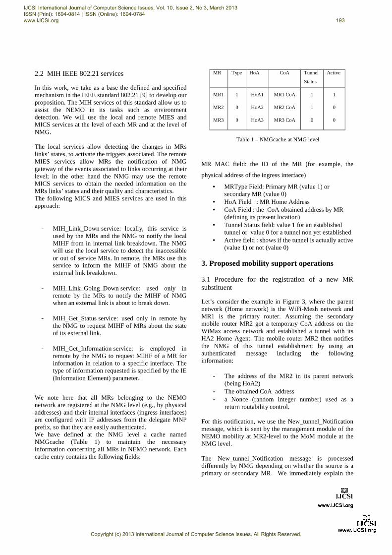
We note here that all MRs belonging to the NEMO network are registered at the NMG level (e.g., by physical addresses) and their internal interfaces (ingress interfaces) are configured with IP addresses from the delegate MNP prefix, so that they are easily authenticated. We have defined at the NMG level a cache named NMGcache (Table 1) to maintain the necessary information concerning all MRs in NEMO network. Each cache entry contains the following fields:
• HoA Field : MR Home Address • CoA Field : the CoA obtained address by MR
(defining its present location) • Tunnel Status field: value 1 for an established
tunnel or value 0 for a tunnel non yet established • Active field : shows if the tunnel is actually active
(value 1) or not (value 0) 3. Proposed mobility support operations
3.1 Procedure for the registration of a new MR substituent
Let’s consider the example in Figure 3, where the parent network (Home network) is the WiFi-Mesh network and MR1 is the primary router. Assuming the secondary mobile router MR2 got a temporary CoA address on the WiMax access network and established a tunnel with its HA2 Home Agent. The mobile router MR2 then notifies the NMG of this tunnel establishment by using an authenticated message including the following information:
- The address of the MR2 in its parent network (being HoA2)
- The obtained CoA address - a Nonce (random integer number) used as a
return routability control. For this notification, we use the New_tunnel_Notification message, which is sent by the management module of the NEMO mobility at MR2-level to the MoM module at the NMG level. The New_tunnel_Notification message is processed differently by NMG depending on whether the source is a primary or secondary MR. We immediately explain the
Table 1 – NMGcache at NMG level
IJCSI International Journal of Computer Science Issues, Vol. 10, Issue 2, No 3, March 2013 ISSN (Print): 1694-0814 | ISSN (Online): 1694-0784 www.IJCSI.org 193
Copyright (c) 2013 International Journal of Computer Science Issues. All Rights Reserved.
treatment to the cases where the sender is a secondary MR, and the case where the sender is the primary MR will be explained later. New_tunnel_Notification message sent by MRupdates MR2 entry of its NMGcache. Then, it transmits to MR1 the obtained information from MRcommunicate the information to its Home Agent to carry out the registration of MR2 as a substituent of MR1. This request is done by sending a New_Sub_Reg the MoM (NMG) to the NEMO module of MR1.
The MR1 Router in its turn sends to its Home Agent HA1 a Sub_Reg_Request message containing information sent by NMG. Upon receiving this message, the HA1 sends to MR2 a message of invitation (Sub_Reg_Invite). This message includes the following information:
treatment to the cases where the sender is a secondary MR, and the case where the sender is the primary MR will be
New_tunnel_Notification message sent by MR2, NMG . Then, it transmits to
MR1 the obtained information from MR2 requesting it to communicate the information to its Home Agent to carry
as a substituent of MR1. This request is done by sending a New_Sub_Reg message by
) to the NEMO module of MR1.
The MR1 Router in its turn sends to its Home Agent HA1 a Sub_Reg_Request message containing information sent
is message, the HA1 sends to ssage of invitation to registration
This message includes the following information:
• the Nonce generated by MR• a Nonce generated this time by HA1
This message arrives at MR2MR2 checks the validity of the message. If the message is valid, it answers HA1 with a Substitute_ BU message (substitute Binding Update) including:
• Its temporary address CoA• MNP prefix • the Nonce generated by HA1
After checking the validity of this message, HMR2 as a substituent for MR1 in its binding cache and sends to MR2 a message Substitute_BACK (substitute Binding Acknowledgement). In parallel, HA1 sends a Substitute_Reg_Notification message to MR1 to inform it that MR2 was registered as a suis immediately forwardedSubstitute_Reg_Confirmation message to updates its NMGcache. This pro4. The tunnels established with HA1 are either on open state or a closed state according to whether the tunnel is currently used to convey the traffic or not. The new tunnel established between MR2 and HA1 is initially put on the closed state, expecting an order of swing to the open state. A possible scenario iswhere primary router MR1 has no link with the access networks, and that NEMO network is being served by one of its secondary mobile routers. In this case, when MR1 establishes a new tunnel with HA1, this latter is put automatically at the opened New_tunnel_Notification message sent by MR1 to simply induces a shunting by (outbound) on MR1. Unless a policy of routing is being implemented at the level of the HA1, this latter should always use by prioHA1-MR1 tunnel (primary tunnel). The tunnel already open with secondary MR can either be used simultaneously with the primary tunnel or simply closed. 3.2 Changes at the level of the Binding Cache
In NEMO BS [14], a mobile router can register only CoA address at its HA. Consequently, the registration of multiple CoAs with only one HoA address is not possible. In order to settle this problem and to allow the secondary mobile routers to be registered at HA1 of the primary mobile router, we have mobinding cache of HA1 to take into account the information on the possible mobile substituent routers.
principles based on NMG
the Nonce generated by MR2 a Nonce generated this time by HA1
2 via its Home Agent HA2. hecks the validity of the message. If the message is
valid, it answers HA1 with a Substitute_ BU message (substitute Binding Update) including:
Its temporary address CoA
the Nonce generated by HA1 checking the validity of this message, HA1 registers as a substituent for MR1 in its binding cache and
a message Substitute_BACK (substitute Binding Acknowledgement). In parallel, HA1 sends a Substitute_Reg_Notification message to MR1 to inform it
was registered as a substituent. This information forwarded by means of a
Substitute_Reg_Confirmation message to NMG which . This process is illustrated in Figure
The tunnels established with HA1 are either on open state according to whether the tunnel is
currently used to convey the traffic or not. The new tunnel and HA1 is initially put on the
closed state, expecting an order of switching to make it swing to the open state. A possible scenario is the case where primary router MR1 has no link with the access networks, and that NEMO network is being served by one of its secondary mobile routers. In this case, when MR1 establishes a new tunnel with HA1, this latter is put automatically at the opened state by HA1. The New_tunnel_Notification message sent by MR1 to NMG simply induces a shunting by NMG of the outgoing traffic
Unless a policy of routing is being implemented at the level of the HA1, this latter should always use by priority
MR1 tunnel (primary tunnel). The tunnel already open with secondary MR can either be used simultaneously with the primary tunnel or simply
3.2 Changes at the level of the Binding Cache
], a mobile router can register only one CoA address at its HA. Consequently, the registration of multiple CoAs with only one HoA address is not possible. In order to settle this problem and to allow the secondary mobile routers to be registered at HA1 of the primary mobile router, we have modified the structure of the binding cache of HA1 to take into account the information on the possible mobile substituent routers.
IJCSI International Journal of Computer Science Issues, Vol. 10, Issue 2, No 3, March 2013 ISSN (Print): 1694-0814 | ISSN (Online): 1694-0784 www.IJCSI.org 194
Copyright (c) 2013 International Journal of Computer Science Issues. All Rights Reserved.
Fig. 4
We have added three fields (Table 2):
• Type: This indicates if the registered MR is primary (value 1) or secondary (
• Tunnel: This indicates if this tunnel is open (value 1) or closed (value 0) to the data traffic. Once established, the tunnel is by default open to the signalization traffic and closed to the dtraffic.
Prefix CoA Type
MNP
MNP
---
MR1 CoA
MR2 CoA
---
1
0
---
3.3 Link break down detection
We use the approach based on MIH_Link_Going_Down service for the breakdown detection of MR links
Table 2 – New Binding Cache for the CoAs multiple registration support
Fig. 4 – Procedure of MR substituent registration
registered MR is rimary (value 1) or secondary (value 0).
Tunnel: This indicates if this tunnel is open to the data traffic.
Once established, the tunnel is by default open to traffic and closed to the data
Tunnel
1
0
---
pproach based on MIH_Link_Going_Down for the breakdown detection of MR links
presenting open tunnels with the primaapproach, in order to activate the tunnel of a MR substituent before the activation of LD trigger, we use the Link_Going_Down (trigger LGD) event allowing the prediction of the links break down. The LGD trigger will be used with a preset threshold:
��� ��
where ��� is the received signal strength (RSS) ��� is the threshold strength below which the link is considered broken down �� is the LGD co 1 (typical values: 1.05, 1.So, in the same manner, if a LGD event is generated by the external interface of a MR, the MIHF of the MR sends this event (remote MIH_LinkGoing_Down) to the MIHF of NMG, this latter notifies immediately the 4. Handover soft procedure (tunnel switching)
Let’s consider again the example in that the moving of NEMO network makes its primary MR
New Binding Cache for the CoAs multiple registration support
presenting open tunnels with the primary HA. In this approach, in order to activate the tunnel of a MR substituent before the activation of LD trigger, we use the Link_Going_Down (trigger LGD) event allowing the prediction of the links break down. The LGD trigger will
eshold:
�����
is the received signal strength (RSS) is the threshold strength below which the link
is considered broken down LGD coefficient slightly superior to
1 (typical values: 1.05, 1.10, …) So, in the same manner, if a LGD event is generated by the external interface of a MR, the MIHF of the MR sends this event (remote MIH_LinkGoing_Down) to the MIHF of
immediately the MoM module.
Handover soft procedure (tunnel switching)
consider again the example in Figure 3. Assuming of NEMO network makes its primary MR
IJCSI International Journal of Computer Science Issues, Vol. 10, Issue 2, No 3, March 2013 ISSN (Print): 1694-0814 | ISSN (Online): 1694-0784 www.IJCSI.org 195
Copyright (c) 2013 International Journal of Computer Science Issues. All Rights Reserved.
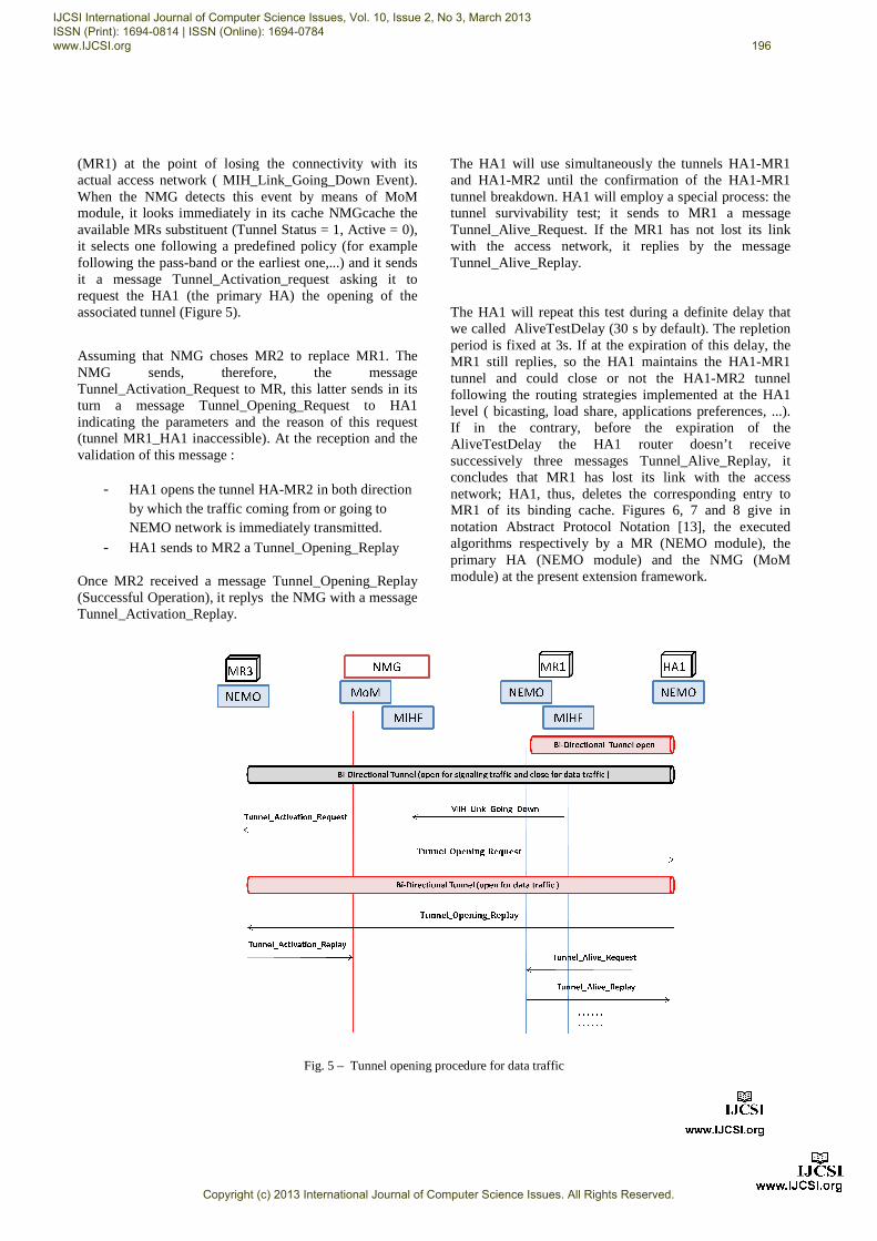
(MR1) at the point of losing the connectivity with itsactual access network ( MIH_Link_Going_Down EventWhen the NMG detects this event by means of module, it looks immediately in its cache available MRs substituent (Tunnel Status = 1, Active = 0), it selects one following a predefined policy (ffollowing the pass-band or the earliest one,...) and it sends it a message Tunnel_Activation_request asking it to request the HA1 (the primary HA) the opening of associated tunnel (Figure 5).
Assuming that NMG choses MR2 to replace MR1. ThNMG sends, therefore, the messaTunnel_Activation_Request to MR, this latter sends in its turn a message Tunnel_Opening_Request to HA1 indicating the parameters and the reason of this request (tunnel MR1_HA1 inaccessible). At the reception and the validation of this message :
- HA1 opens the tunnel HA-MR2 in both direction by which the traffic coming from or going to NEMO network is immediately transmitted
- HA1 sends to MR2 a Tunnel_Opening_Replay
Once MR2 received a message Tunnel_Opening_Replay (Successful Operation), it replys the NMGTunnel_Activation_Replay.
Fig. 5
at the point of losing the connectivity with its MIH_Link_Going_Down Event).
detects this event by means of MoM , it looks immediately in its cache NMGcache the
available MRs substituent (Tunnel Status = 1, Active = 0), it selects one following a predefined policy (for example
band or the earliest one,...) and it sends it a message Tunnel_Activation_request asking it to request the HA1 (the primary HA) the opening of the
to replace MR1. The sends, therefore, the message
MR, this latter sends in its turn a message Tunnel_Opening_Request to HA1 indicating the parameters and the reason of this request (tunnel MR1_HA1 inaccessible). At the reception and the
MR2 in both direction by which the traffic coming from or going to
network is immediately transmitted.
HA1 sends to MR2 a Tunnel_Opening_Replay
received a message Tunnel_Opening_Replay NMG with a message
The HA1 will use simultaneously the tunnels HA1and HA1-MR2 until the confirmation of the HA1tunnel breakdown. HA1 will employ a special process: tunnel survivability test; it sends to MR1 a message Tunnel_Alive_Request. If the MR1 has not lost its link with the access network, it replTunnel_Alive_Replay. The HA1 will repeat this test during a definite delay that we called AliveTestDelay (30 s bperiod is fixed at 3s. If at the expiration of this delay, the MR1 still replies, so the HA1 maintunnel and could close or not the HA1following the routing strategies implemented at the HA1 level ( bicasting, load share, applications preferences, ...). If in the contrary, before the expiration of the AliveTestDelay the HA1 router doesn’t receive successively three messages Tunnel_Alive_Replay, it concludes that MR1 has lost its link with the access network; HA1, thus, deletes the corresponding entry toMR1 of its binding cache. Figures 6notation Abstract Protocol Notation [13algorithms respectively by a MRprimary HA (NEMO module) and the module) at the present extension framework.
Fig. 5 – Tunnel opening procedure for data traffic
The HA1 will use simultaneously the tunnels HA1-MR1 until the confirmation of the HA1-MR1
will employ a special process: the test; it sends to MR1 a message
Tunnel_Alive_Request. If the MR1 has not lost its link with the access network, it replies by the message
The HA1 will repeat this test during a definite delay that we called AliveTestDelay (30 s by default). The repletion period is fixed at 3s. If at the expiration of this delay, the MR1 still replies, so the HA1 maintains the HA1-MR1
and could close or not the HA1-MR2 tunnel following the routing strategies implemented at the HA1
casting, load share, applications preferences, ...). If in the contrary, before the expiration of the AliveTestDelay the HA1 router doesn’t receive successively three messages Tunnel_Alive_Replay, it concludes that MR1 has lost its link with the access
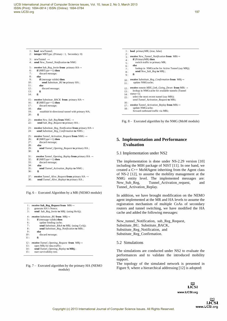
work; HA1, thus, deletes the corresponding entry to MR1 of its binding cache. Figures 6, 7 and 8 give in
n Abstract Protocol Notation [13], the executed algorithms respectively by a MR (NEMO module), the
(NEMO module) and the NMG (MoM the present extension framework.
IJCSI International Journal of Computer Science Issues, Vol. 10, Issue 2, No 3, March 2013 ISSN (Print): 1694-0814 | ISSN (Online): 1694-0784 www.IJCSI.org 196
Copyright (c) 2013 International Journal of Computer Science Issues. All Rights Reserved.
receive Sub_Reg_Invite from primary HA→ if (MRType==1) then discard message; else if (message valide) then send Substitute_BU to primary HA ; else discard message; fi fi
receive Substitute_BACK from primary HA→ if (MRType==1) then discard message;
else establish bi-directional tunnel with primary HA; fi
receive New_Sub_Reg from NMG → send Sub_Reg_Request to primary HA ;
receive Substitute_Reg_Notification from primary HA→ send Substitute_Reg_Confirmation to NMG ;
receive Tunnel_Activation_Request from NMG → if (MRType==1) then discard message;
else send Tunnel_Opening_Request to primary HA ;
fi
receive Tunnel_Opening_Replay from primary HA → if (MRType==1) then discard message;
else send Tunnel_Activation_Replay to NMG ;
fi
receive Tunnel_Alive_Request from primary HA → send Tunnel_Alive_Replayt to primary HA ;
Fig. 6 – Executed Algorithm by a MR (NEMO module)
Fig. 7 – Executed algorithm by the primary HA (NEMO
module)
1 : 2 : 3 : 4 : 5 : 6 : 7 : 8 : 9 :
10 : 11 :
12 : 13 : 14 : 15 :
16 : 17 : 18 :
bool primaryMR; (true, false)
receive New_Tunnel_Notification from MRi→ if (PrimaryMR) then switch traffic to primary MR; else lookup in NMGcache for Active Tunnel (say MRj); send New_Sub_Reg to MRj ; fi
receive Substitute_Reg_Confirmation from MRj→ update NMGcache;
receive remote MIH_Link_Going_Down from MRi → lookup in NMGcache for available tunnels (Tunnel
status=1); select the most recent tunnel (say MRi); send Tunnel_Activation_Request to MRi;
receive Tunnel_Activation_Replay from MRi→ update NMGcache; forward outbound traffic via MRi;
Fig. 8 – Executed algorithm by the NMG (MoM module)
5. Implementation and Performance
Evaluation
5.1 Implementation under NS2
The implementation is done under NS-2.29 version [10] including the MIH package of NIST [11]. In one hand, we created a C++ MoMAgent inheriting from the Agent class of NS-2 [12], to assume the mobility management at the NMG entity level. The implemented messages are: New_Sub_Reg, Tunnel_Activation_request, and Tunnel_Activation_Replay. In addition, we have brought modification on the NEMO agent implemented at the MR and HA levels to assume the registration mechanism of multiple CoAs of secondary routers and tunnel switching, we have modified the HA cache and added the following messages: New_tunnel_Notification, sub_Reg_Request, Substitute_BU, Substitute_BACK, Substitute_Reg_Notification, and Substitute_Reg_Confirmation. 5.2 Simulations
The simulations are conducted under NS2 to evaluate the performances and to validate the introduced mobility support. The topology of the simulated network is presented in Figure 9, where a hierarchical addressing [12] is adopted:
1 : 2 : 3 :
4 : 5 : 6 : 7 : 8 : 9 :
10 : 11 :
12 : 13 : 14 : 15 :
receive Sub_Reg_Request from MRi→ generate HA’s Nonce; send Sub_Reg_Invite to MRj (using HoAj);
receive Substitute_BU from MRj→ if (message valide) then update binding cache; send Substitute_BAck to MRj (using CoAj); send Substitute_Reg_Notification to MRi ; else discard message; fi
receive Tunnel_Opening_Request from MRj→ open MRj for data traffic; send Tunnel_Opening_Replay to MRj ; start survivability test;
IJCSI International Journal of Computer Science Issues, Vol. 10, Issue 2, No 3, March 2013 ISSN (Print): 1694-0814 | ISSN (Online): 1694-0784 www.IJCSI.org 197
Copyright (c) 2013 International Journal of Computer Science Issues. All Rights Reserved.
• Node 0: a router (0.0.0) presenting four wired interfaces
• Node 1: a corresponding node • Node 2: the HA1 Home Agent (4.0.0) of the
primary router MR1. • Node 3: a base station IEEE 802.11 (access
router AR1 (1.0.0)) with a coverage of 100m. • Node 4: a base station IEEE 802.16 (access
router AR2 (2.0.0)) with a coverage of 1000m. • Node 5: the primary mobile router MR1 (4.1.0)
presenting two interfaces: an external interface (802.11) and an internal interface (802.3) linked to NMG.
• Node 6: a secondary mobile routerpresenting two interfaces: an external interface (802.16) and an internal interface (802.3) linked to NMG.
• Node 7: the NMG router (4.3.0) presenting three wired interfaces (802.3).
• Node 8: an MNN (4.3.1) linked directly to
Fig. 9 – Topology of simulated NEMO network
0.0.0) presenting four wired
CN (3.0.0). Node 2: the HA1 Home Agent (4.0.0) of the
Node 3: a base station IEEE 802.11 (access router AR1 (1.0.0)) with a coverage of 100m.
n IEEE 802.16 (access router AR2 (2.0.0)) with a coverage of 1000m. Node 5: the primary mobile router MR1 (4.1.0) presenting two interfaces: an external interface (802.11) and an internal interface (802.3) linked
Node 6: a secondary mobile router MR2 (4.2.0) presenting two interfaces: an external interface (802.16) and an internal interface (802.3) linked
router (4.3.0) presenting three
Node 8: an MNN (4.3.1) linked directly to NMG.
The characteristics of the links and those of the bandwidth as well and the delay are referred in traffic CBR is sent by the CN towards a node MNN of the NEMO network (PacketSizems). The simulation time is fixed at 20 The NS-2 simulator doesn’t withstand the mobility of a full network, for this reason we have emulated the movement of NEMO network by reducing the emission power of the base station IEEE 802.11 (access router AR1 (1.0.0)). Following the importance of we activate either trigger LGD or trigger LD.We consider the following simulation plan:At the beginning of the simulation (from t=0 to t=5s), NEMO network has a single link with the internet network, the link with the base station 802.1base station 802.16 being deactivated. Consequently, a single tunnel is available, the one established between MR1 (the primary router) and its HA. At t= 5s, the base station 802.16 is active, a second tunnel is established between the secondHA, MR2 is registered in HA as a substituent of MR1
eristics of the links and those of the bandwidth
as well and the delay are referred in Figure 9. A streaming traffic CBR is sent by the CN towards a node MNN of the
(PacketSize = 768 bytes, Interval = 16 . The simulation time is fixed at 20s.
2 simulator doesn’t withstand the mobility of a full network, for this reason we have emulated the movement of NEMO network by reducing the emission power of the base station IEEE 802.11 (access router AR1 (1.0.0)). Following the importance of the caused power, we activate either trigger LGD or trigger LD. We consider the following simulation plan: At the beginning of the simulation (from t=0 to t=5s), NEMO network has a single link with the internet network, the link with the base station 802.11 (AR1), the base station 802.16 being deactivated. Consequently, a single tunnel is available, the one established between MR1 (the primary router) and its HA. At t= 5s, the base station 802.16 is active, a second tunnel is established between the secondary router MR2 and the HA, MR2 is registered in HA as a substituent of MR1.
IJCSI International Journal of Computer Science Issues, Vol. 10, Issue 2, No 3, March 2013 ISSN (Print): 1694-0814 | ISSN (Online): 1694-0784 www.IJCSI.org 198
Copyright (c) 2013 International Journal of Computer Science Issues. All Rights Reserved.
At t=10s, we activate the trigger Link_Going_Down at MR1 level, and this by reducing suitably the emission power of the base station IEEE 802.11. Then, at t=10 s, t= 10.05 s, t= 10.1 s, t = 10.15 s, t = 10.2 s, …., t = 10.5 s, in the same way with the previous, we activate the trigger Link_Down to scan the rang [0,500 ms] of the possible values for the TimeInterval parameter associated to LGD trigger. This manipulation will allow us to determine the threshold for which it is possible to ensure a seamless connectivity. 5.3 Results
We have presented in Figure 10, the services interruption time according to TimeInterval parameter. It is determined by the past time between the reception of the last data packet (traffic CBR) via MR1 and the reception of the first data packet via MR2. It is obvious that the connexion delay is inversely proportional to TimeInterval, more this latter increases, more is the chance to finish the tunnels switching operation before the current link breaks down.
Value 0 for TimeInterval means that the used trigger for the activation of the tunnel commutation is the Link_Down, i.e. we are dealing with a hard handover. We note the threshold value of 250 ms for the TimeInterval, for which the disconnection delay is null. For applications such as the vision conference and the voice on IP (VoIP), a delay of 50 ms is tolerable [20], thus a threshold of 200 ms for TimeInterval can be kept. Notice that we have used a RTT maximal value between AR2 and HA given by the reference [21], that is 200 ms.
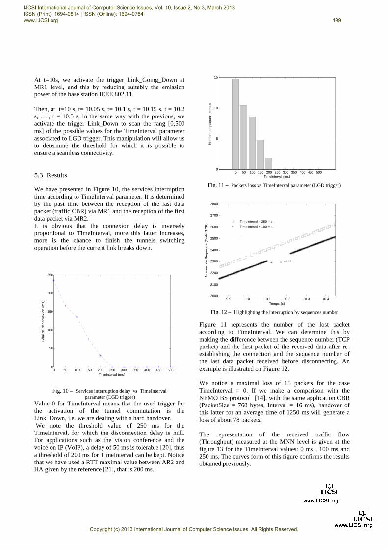
Fig. 11 – Packets loss vs TimeInterval parameter (LGD trigger)
Fig. 12 – Highlighting the interruption by sequences number
Figure 11 represents the number of the lost packet according to TimeInterval. We can determine this by making the difference between the sequence number (TCP packet) and the first packet of the received data after re-establishing the connection and the sequence number of the last data packet received before disconnecting. An example is illustrated on Figure 12. We notice a maximal loss of 15 packets for the case TimeInterval = 0. If we make a comparison with the NEMO BS protocol [14], with the same application CBR (PacketSize = 768 bytes, Interval = 16 ms), handover of this latter for an average time of 1250 ms will generate a loss of about 78 packets. The representation of the received traffic flow (Throughput) measured at the MNN level is given at the figure 13 for the TimeInterval values: 0 ms , 100 ms and 250 ms. The curves form of this figure confirms the results obtained previously.
0 50 100 150 200 250 300 350 400 450 5000
50
100
150
200
250
TimeInterval (ms)
Dél
ai d
e dé
conn
exio
n (m
s)
0 50 100 150 200 250 300 350 400 450 5000
5
10
15
TimeInterval (ms)
Nom
bre
de p
aque
ts p
erdu
s
10.1 10.210 10.3 10.49.92000
2100
2200
2300
2400
2500
2600
2700
2800
Temps (s)
Num
ero
de S
eque
nce
(Tra
fic T
CP
) TimeInterval = 250 ms
TimeInterval = 100 ms
data3
data4
IJCSI International Journal of Computer Science Issues, Vol. 10, Issue 2, No 3, March 2013 ISSN (Print): 1694-0814 | ISSN (Online): 1694-0784 www.IJCSI.org 199
Copyright (c) 2013 International Journal of Computer Science Issues. All Rights Reserved.
Fig. 13 – Throughput vs TimeInterval (LGD trigger)
6. Conclusion
In this paper, we have described a new approach for mobility management in multiple mobile routers multihomed NEMO context. The proposed solution is infrastructure independent; it doesn’t require any change in Internet architecture, while ensuring a seamless connectivity to meet real time applications needs and demands in QoS. We considered a multihomed NEMO network with several MRs domiciled in different HAs. This architecture is based on the introduction of the notions of primary router and secondary router, and the integration of a new entity called NMG (NeMo Gateway) inside the mobile network, playing the role of a gateway between the embarked MNNs and the MRs, and which the principle task is the management of handovers using local and remote MIH IEEE 802.21 services. We extended the NEMO BS protocol by the registration support of the secondary routers (substituent MRs), and of the tunnel switching support. References [1] C. Ng, E. Paik, T. Ernst, M. Bagnulo, “Analysis of Multihoming in
Network Mobility Support,” IETF, RFC 4980, October 2007. [2] E. K. Paik, H. S. Cho, T. Ernst and Y. H. Choi, "Load sharing and
session preservation with multiple mobile routers for large scale network mobility," The proceedings of AINA 2004: Page(s):393 - 398 Vol.1.2004.
[3] F. Guo, J. Chen, W. Li, and T. Chiueh, ”Experiences in Building A Multihoming Load Balancing System,” Proc. of IEEE INFOCOM 2004, Mar 2004.
[4] S. H. Cho, J. K. Na and C. K. Kim, "A dynamic load sharing mechanism in multihomed mobile networks," ICC 2005 16-20 May 2005 Page(s):1459 - 1463 Vol. 3. 2005.
[5] R. Kuntz and J. Lorchat. Building Fault Tolerant Networks using a multihomed Mobile Router: a Case Study. In Asian Internet Engineering Conference (AINTEC) 2006, Bangkok,Thailand, November 2006.
[6] K. Mitsuya, K. Tasaka, and R. Wakikawa. A Policy Data Set for Flow Distribution. Internet Draft draft-mitsuya-monami6- flow-distribution-policy-02.txt, October 2006.
[7] C. Park, N. Choi, E. Paik, T. Kwon and Y. Choi, “Multiple Interface/Prefix Selection for Virtual Mobile Networks”, ICACT, February 2008.
[8] IETF, Internet Draft, Feb. 2004.Q. Wang, R. Atkinson, and J.Dunlop, “Towards Always Best Connected Multi-Access: the MULTINET Approach”, IWCMC '08. August 2008.
[9] IEEE 802.21-2008, Media Independent Handover Services. 2008. [10] NS-2 Network Simulator, http://www.isi.edu/nsnam/ns [11] The Network Simulator NS-2 NIST add-on—IEEE 802.21 model
(based on IEEE P802.21/D03.00), National Institute of Standards and Technology (NIST), January 2007.
[12] The VINT Project. The ns Manual. http://www.isi.edu/nsnam/ns/ns-documentation.html.
[13] M. G. Gouda, “Elements of Network Protocol Design,” John Wiley and Sons, 1998.
[14] V. Devarapalli, R. Wakikawa, A. Petrescu, and P. Thubert, "Network Mobility (NEMO) Basic Support Protocol," IETF, RFC 3963, January 2005..
[15] Dinakaran M, P. Balasubramanie, ” Performance Tuning of Data Transfer in Vehicular Networks”, IJCSI -Volume 9, Issue 1, pp.350-356, January 2012.
[16] Q.B Mussabbir, W. Yao. Optimized FMIPv6 using IEEE 802.21 MIH Services in Vehicular Networks. IEEE Transactions on Vehicular Technology. Special Issue on Vehicular Communications Networks, 2007.
[17] H. Lin, H. Labiod. Hybrid handover optimization for multiple mobile routers-based multihomed NEMO networks, in: Proceedings of IEEE International Conference on Pervasive Service, Istanbul. 2007.
[18] Z. Huang, Y. Yang, H. Hu and K. Lin. A fast handover scheme based on multiple mobile router cooperation for a train-based mobile network Int. J. Modelling, Identification and Control, Vol. 10, No. 3/4, pp 202-212. 2010.
[19] G. Jeney, L. Bokor and Z. Mihaly. GPS aided predictive handover management for multihomed NEMO configurations. 9th International Conference on Intelligent Transport Systems Telecommunications, pp 69-73. 2009.
[20] Neal seitz, ITU-T QoS Standards for IP-based Networks. Standards Report, IEEE Communications magazine, June 2003.
[21] Details for North Americ Internet Traffic Report. 2012 http://www.internettrafficreport.com/namerica.htm
IJCSI International Journal of Computer Science Issues, Vol. 10, Issue 2, No 3, March 2013 ISSN (Print): 1694-0814 | ISSN (Online): 1694-0784 www.IJCSI.org 200
Copyright (c) 2013 International Journal of Computer Science Issues. All Rights Reserved.