34
Initializing of thermal runaway for lithium-ion cells Workshop JRC, March 8./9. 2018 Petten H. Döring, M. Wörz Zentrum für Sonnenenergie- und Wasserstoff-Forschung Ulm
Initializing of thermal runaway for lithium-ion cells
Workshop JRC, March 8./9. 2018Petten
H. Döring, M. WörzZentrum für Sonnenenergie- und Wasserstoff-Forschung Ulm
- 2 -- 2 -
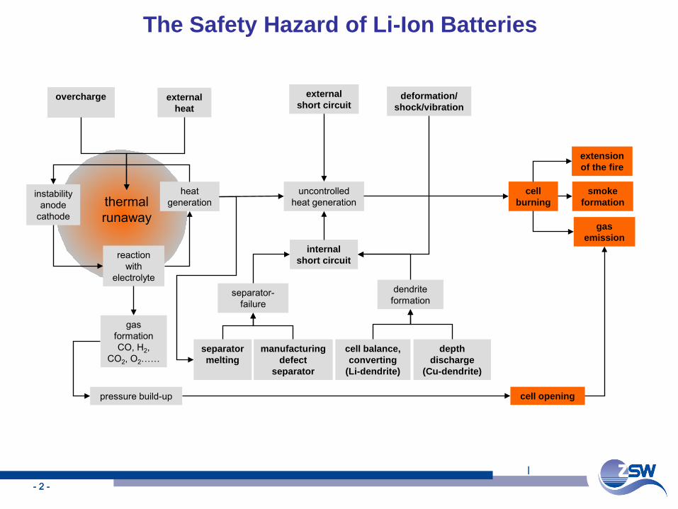
uncontrolled heat generation
cell burning
smoke formation
gas emission
extension of the fire
external heat
external short circuit
deformation/shock/vibration
internal short circuit
dendrite formation
separator-failure
cell balance, converting
(Li-dendrite)
depth discharge
(Cu-dendrite)
separator melting
manufacturing defect
separator
heat generation
overcharge
pressure build-up
instability anode
cathode
reaction with
electrolyte
gas formation CO, H2,
CO2, O2……
cell opening
thermal runaway
The Safety Hazard of Li-Ion Batteries
l
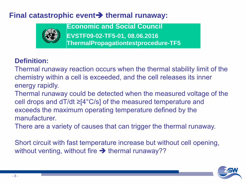
Final catastrophic event thermal runaway:
- 3 -
Definition: Thermal runaway reaction occurs when the thermal stability limit of the chemistry within a cell is exceeded, and the cell releases its inner energy rapidly. Thermal runaway could be detected when the measured voltage of the cell drops and dT/dt ≥[4°C/s] of the measured temperature and exceeds the maximum operating temperature defined by the manufacturer.There are a variety of causes that can trigger the thermal runaway.
Short circuit with fast temperature increase but without cell opening, without venting, without fire thermal runaway??
Economic and Social CouncilEVSTF09-02-TF5-01, 08.06.2016 ThermalPropagationtestprocedure-TF5
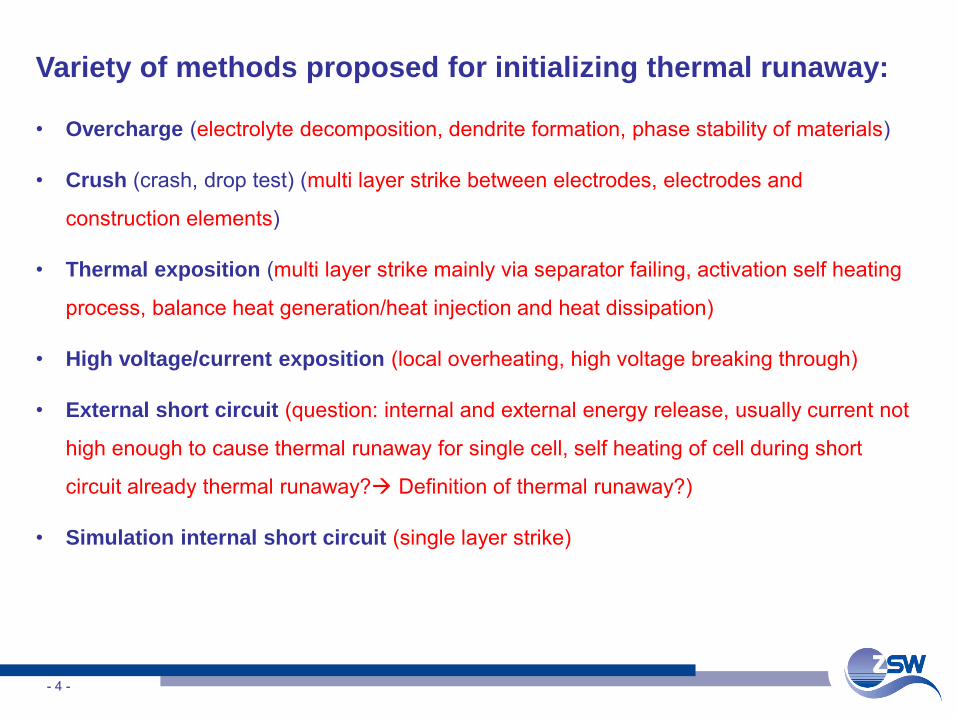
Variety of methods proposed for initializing thermal runaway:
• Overcharge (electrolyte decomposition, dendrite formation, phase stability of materials)
• Crush (crash, drop test) (multi layer strike between electrodes, electrodes and
construction elements)
• Thermal exposition (multi layer strike mainly via separator failing, activation self heating
process, balance heat generation/heat injection and heat dissipation)
• High voltage/current exposition (local overheating, high voltage breaking through)
• External short circuit (question: internal and external energy release, usually current not
high enough to cause thermal runaway for single cell, self heating of cell during short
circuit already thermal runaway? Definition of thermal runaway?)
• Simulation internal short circuit (single layer strike)
- 4 -
Different methods proposed for simulation of internal
short circuit:
• Nail or needle penetration (multi layer strike, extent depends on nail and depth, special
screw penetration)
• Bullet firing through test (multi layer strike)
• Blunt rod test (damage of separator mechanically, single or multilayer strike)
• Incorporation of particles and pressing (single layer strike )
• Incorporation of metals with low melting points (e.g. Wood’s metal, heat exposure for
melting, single layer strike )
- 5 -
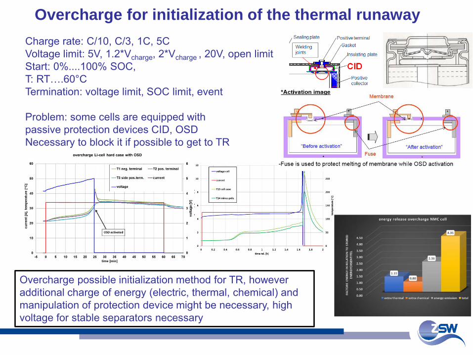
Charge rate: C/10, C/3, 1C, 5CVoltage limit: 5V, 1.2*Vcharge, 2*Vcharge , 20V, open limitStart: 0%....100% SOC, T: RT….60°CTermination: voltage limit, SOC limit, event
Problem: some cells are equipped with passive protection devices CID, OSDNecessary to block it if possible to get to TR
Overcharge for initialization of the thermal runaway
Overcharge possible initialization method for TR, however additional charge of energy (electric, thermal, chemical) and manipulation of protection device might be necessary, high voltage for stable separators necessary
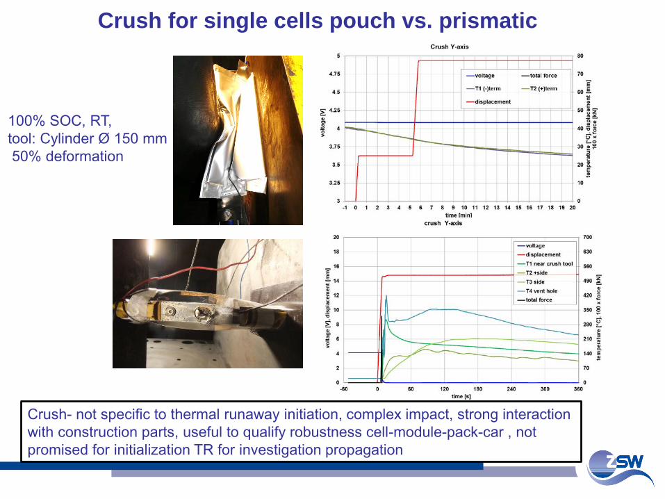
100% SOC, RT, tool: Cylinder Ø 150 mm50% deformation
Crush for single cells pouch vs. prismatic
Crush- not specific to thermal runaway initiation, complex impact, strong interaction with construction parts, useful to qualify robustness cell-module-pack-car , not promised for initialization TR for investigation propagation
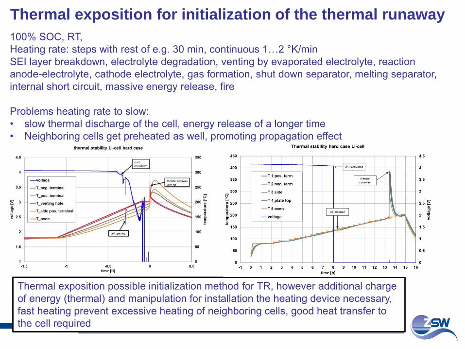
100% SOC, RT, Heating rate: steps with rest of e.g. 30 min, continuous 1…2 °K/minSEI layer breakdown, electrolyte degradation, venting by evaporated electrolyte, reaction anode-electrolyte, cathode electrolyte, gas formation, shut down separator, melting separator, internal short circuit, massive energy release, fire
Problems heating rate to slow: • slow thermal discharge of the cell, energy release of a longer time • Neighboring cells get preheated as well, promoting propagation effect
Thermal exposition for initialization of the thermal runaway
Thermal exposition possible initialization method for TR, however additional charge of energy (thermal) and manipulation for installation the heating device necessary, fast heating prevent excessive heating of neighboring cells, good heat transfer to the cell required
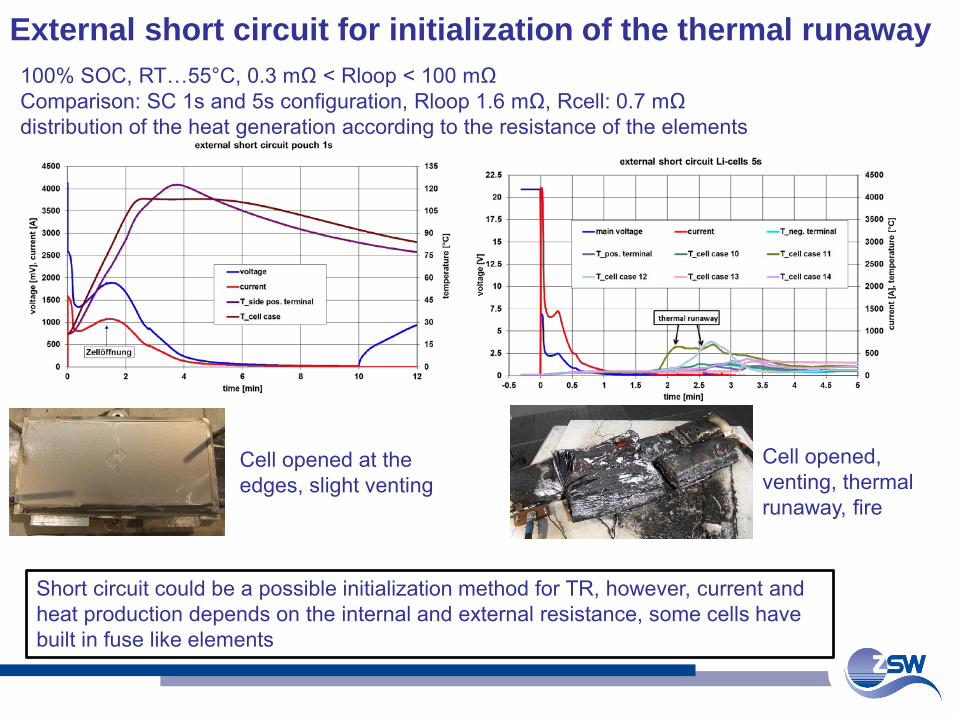
100% SOC, RT…55°C, 0.3 mΩ < Rloop < 100 mΩComparison: SC 1s and 5s configuration, Rloop 1.6 mΩ, Rcell: 0.7 mΩ distribution of the heat generation according to the resistance of the elements
External short circuit for initialization of the thermal runaway
Short circuit could be a possible initialization method for TR, however, current and heat production depends on the internal and external resistance, some cells have built in fuse like elements
Cell opened at the edges, slight venting
Cell opened, venting, thermal runaway, fire
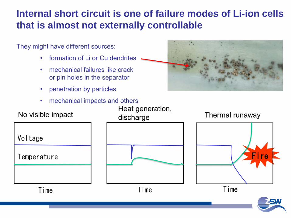
Temperature
Voltage
Thermal runawayNo visible impact
Fire
Heat generation, discharge
Time Time Time
Internal short circuit is one of failure modes of Li-ion cells that is almost not externally controllable
They might have different sources:
• formation of Li or Cu dendrites
• mechanical failures like crack or pin holes in the separator
• penetration by particles
• mechanical impacts and others
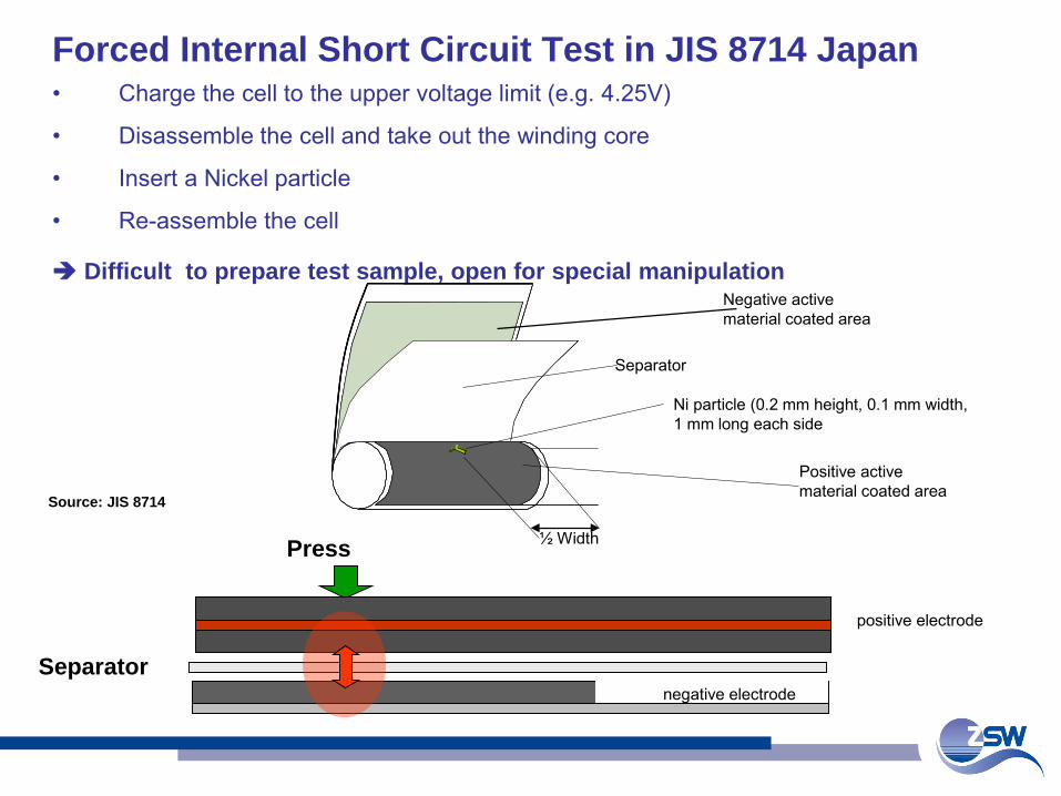
Forced Internal Short Circuit Test in JIS 8714 Japan • Charge the cell to the upper voltage limit (e.g. 4.25V)
• Disassemble the cell and take out the winding core
• Insert a Nickel particle
• Re-assemble the cell
Difficult to prepare test sample, open for special manipulation
Positive activematerial coated area
Negative activematerial coated area
Separator
½ Width
Ni particle (0.2 mm height, 0.1 mm width, 1 mm long each side
Press
Separatornegative electrode
positive electrode
Source: JIS 8714
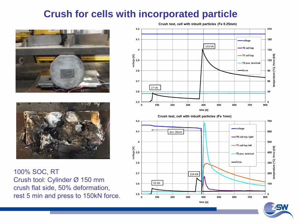
100% SOC, RTCrush tool: Cylinder Ø 150 mmcrush flat side, 50% deformation, rest 5 min and press to 150kN force.
Crush for cells with incorporated particle
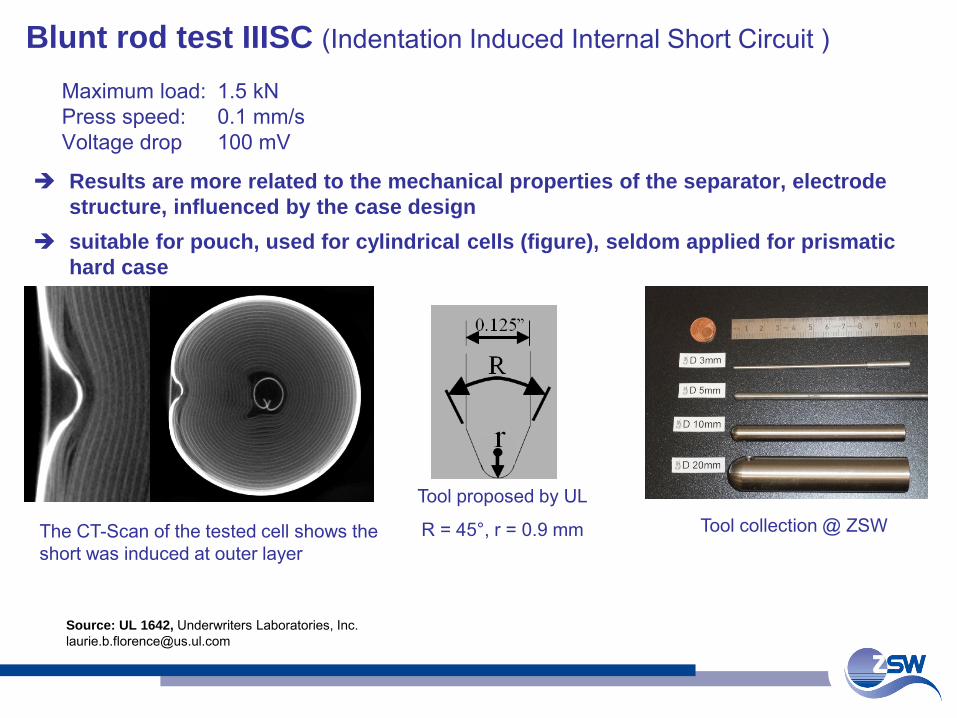
Blunt rod test IIISC (Indentation Induced Internal Short Circuit )
Maximum load: 1.5 kNPress speed: 0.1 mm/s Voltage drop 100 mV
The CT-Scan of the tested cell shows the short was induced at outer layer
Tool proposed by UL
R = 45°, r = 0.9 mm
Source: UL 1642, Underwriters Laboratories, [email protected]
Tool collection @ ZSW
Results are more related to the mechanical properties of the separator, electrode structure, influenced by the case design
suitable for pouch, used for cylindrical cells (figure), seldom applied for prismatic hard case
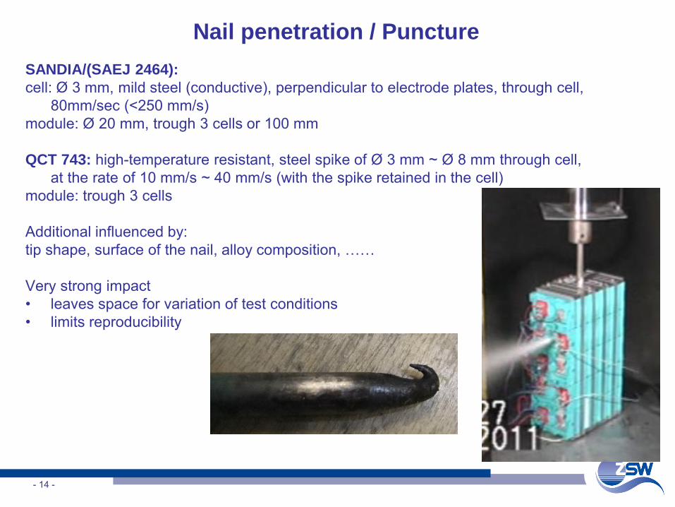
Nail penetration / PunctureSANDIA/(SAEJ 2464): cell: Ø 3 mm, mild steel (conductive), perpendicular to electrode plates, through cell,
80mm/sec (<250 mm/s)module: Ø 20 mm, trough 3 cells or 100 mm
QCT 743: high-temperature resistant, steel spike of Ø 3 mm ~ Ø 8 mm through cell, at the rate of 10 mm/s ~ 40 mm/s (with the spike retained in the cell)
module: trough 3 cells
Additional influenced by: tip shape, surface of the nail, alloy composition, ……
Very strong impact• leaves space for variation of test conditions • limits reproducibility
- 14 -
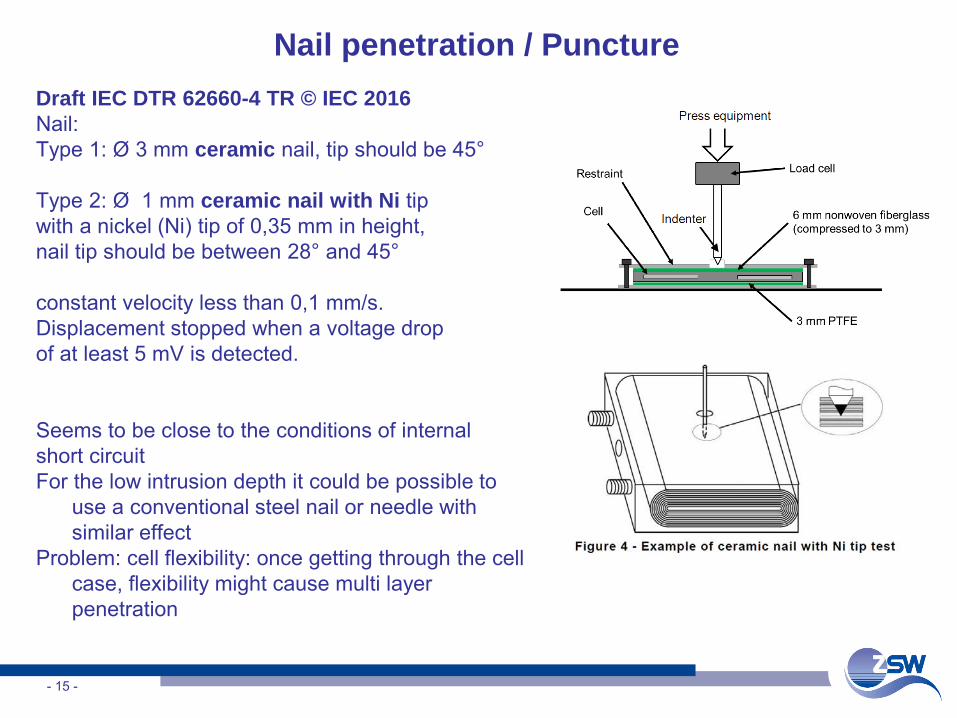
Nail penetration / PunctureDraft IEC DTR 62660-4 TR © IEC 2016 Nail: Type 1: Ø 3 mm ceramic nail, tip should be 45°
Type 2: Ø 1 mm ceramic nail with Ni tip with a nickel (Ni) tip of 0,35 mm in height, nail tip should be between 28° and 45°
constant velocity less than 0,1 mm/s. Displacement stopped when a voltage drop of at least 5 mV is detected.
Seems to be close to the conditions of internal short circuitFor the low intrusion depth it could be possible to
use a conventional steel nail or needle with similar effect
Problem: cell flexibility: once getting through the cell case, flexibility might cause multi layer penetration
- 15 -
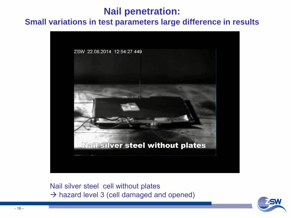
Nail penetration: Small variations in test parameters large difference in results
- 16 -
Nail silver steel cell without plates hazard level 3 (cell damaged and opened)
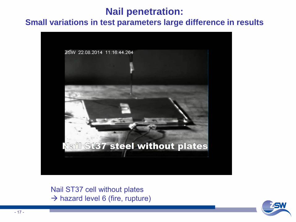
Nail penetration: Small variations in test parameters large difference in results
- 17 -
Nail ST37 cell without plates hazard level 6 (fire, rupture)
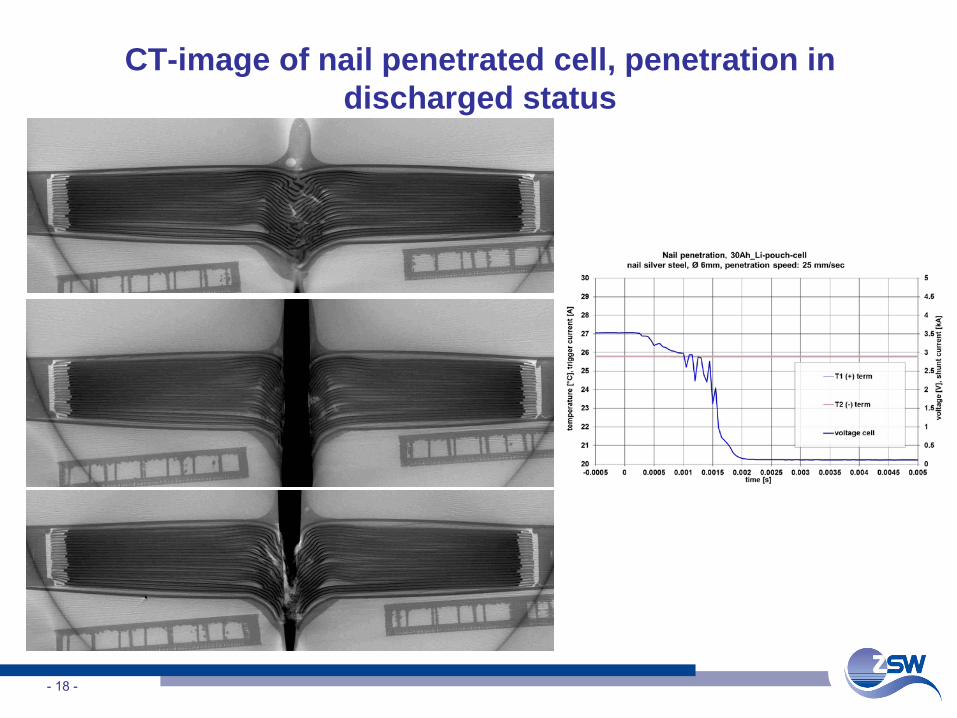
CT-image of nail penetrated cell, penetration in discharged status
- 18 -
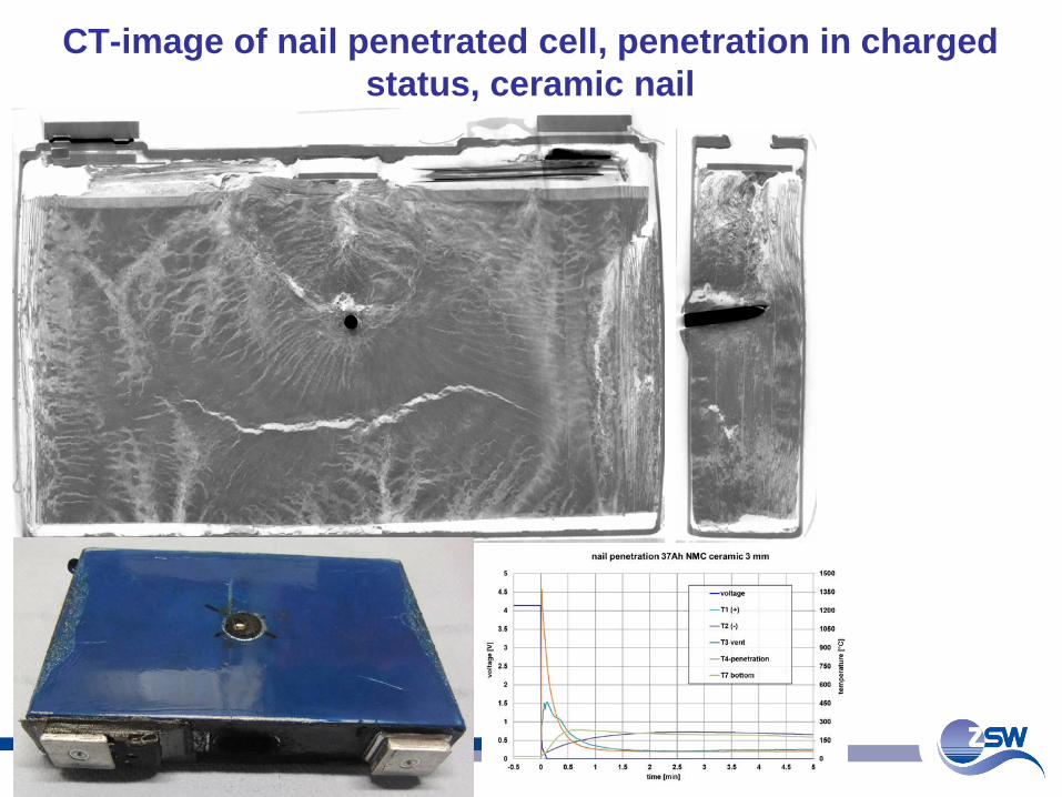
CT-image of nail penetrated cell, penetration in charged status, ceramic nail
- 19 -
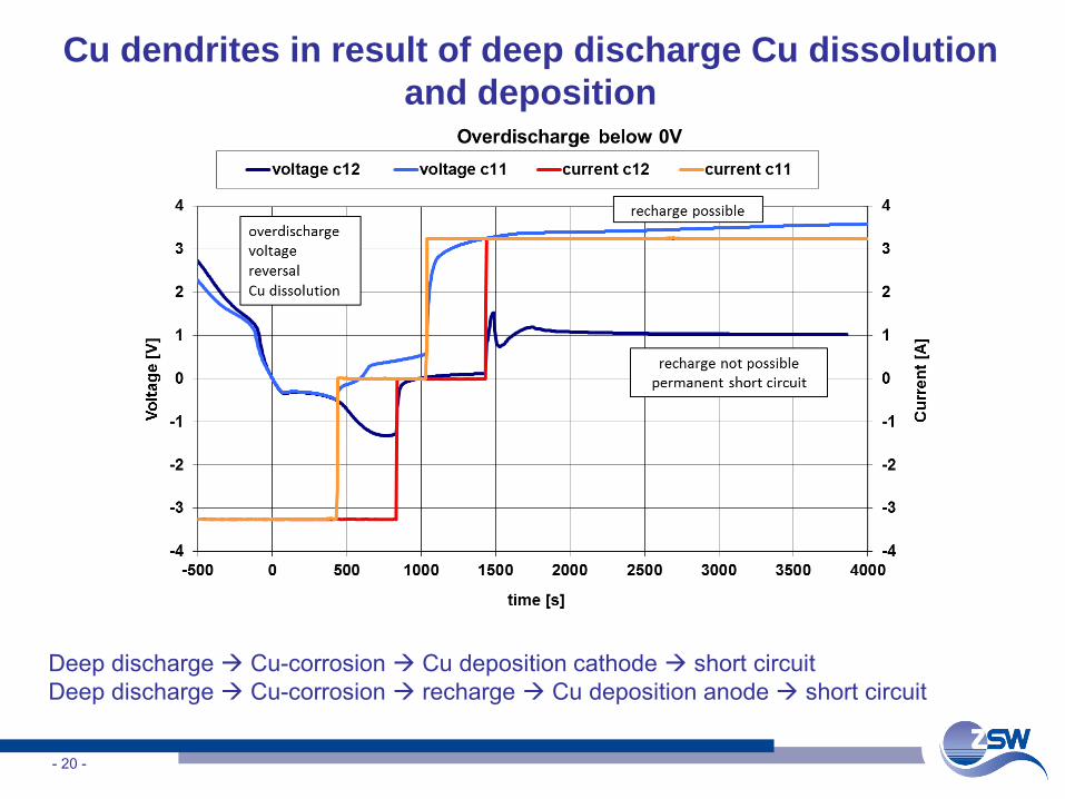
Cu dendrites in result of deep discharge Cu dissolution and deposition
- 20 -
Deep discharge Cu-corrosion Cu deposition cathode short circuitDeep discharge Cu-corrosion recharge Cu deposition anode short circuit
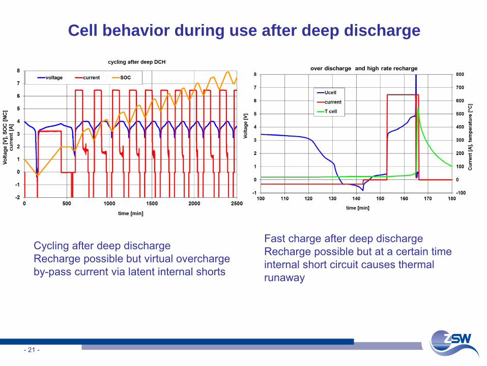
Cell behavior during use after deep discharge
- 21 -
Cycling after deep dischargeRecharge possible but virtual overcharge by-pass current via latent internal shorts
Fast charge after deep dischargeRecharge possible but at a certain time internal short circuit causes thermal runaway
- 22 -
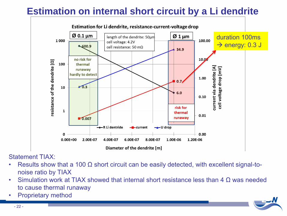
Estimation on internal short circuit by a Li dendrite
Statement TIAX:• Results show that a 100 Ω short circuit can be easily detected, with excellent signal-to-
noise ratio by TIAX• Simulation work at TIAX showed that internal short resistance less than 4 Ω was needed
to cause thermal runaway• Proprietary method
duration 100ms energy: 0.3 J
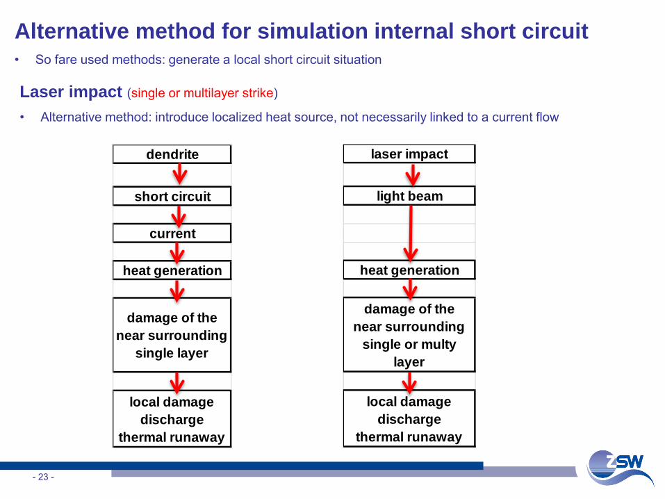
Alternative method for simulation internal short circuit • So fare used methods: generate a local short circuit situation
- 23 -
dendrite
short circuit
current
heat generation
damage of the near surrounding
single layer
local damagedischarge
thermal runaway
laser impact
light beam
heat generation
damage of the near surrounding
single or multy layer
local damagedischarge
thermal runaway
Laser impact (single or multilayer strike)
• Alternative method: introduce localized heat source, not necessarily linked to a current flow
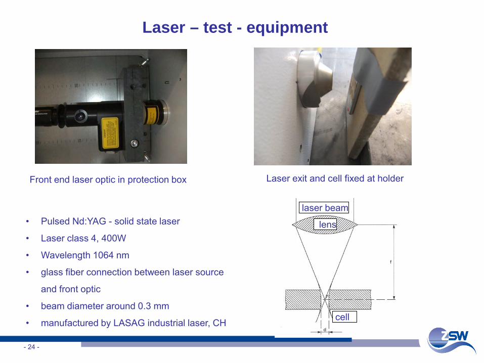
Laser – test - equipment
- 24 -
Front end laser optic in protection box Laser exit and cell fixed at holder
• Pulsed Nd:YAG - solid state laser
• Laser class 4, 400W
• Wavelength 1064 nm
• glass fiber connection between laser source
and front optic
• beam diameter around 0.3 mm
• manufactured by LASAG industrial laser, CH
laser beam
lens
cell
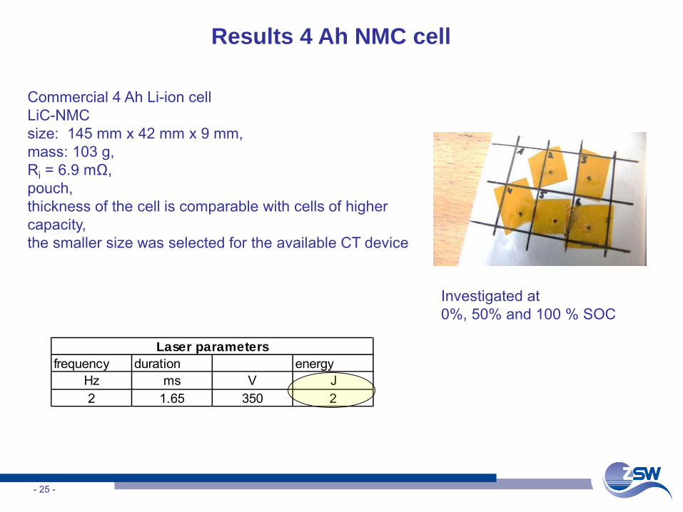
Results 4 Ah NMC cell
- 25 -
Commercial 4 Ah Li-ion cellLiC-NMCsize: 145 mm x 42 mm x 9 mm, mass: 103 g, Ri = 6.9 mΩ, pouch, thickness of the cell is comparable with cells of higher capacity,the smaller size was selected for the available CT device
frequency duration energyHz ms V J2 1.65 350 2
Laser parameters
Investigated at 0%, 50% and 100 % SOC
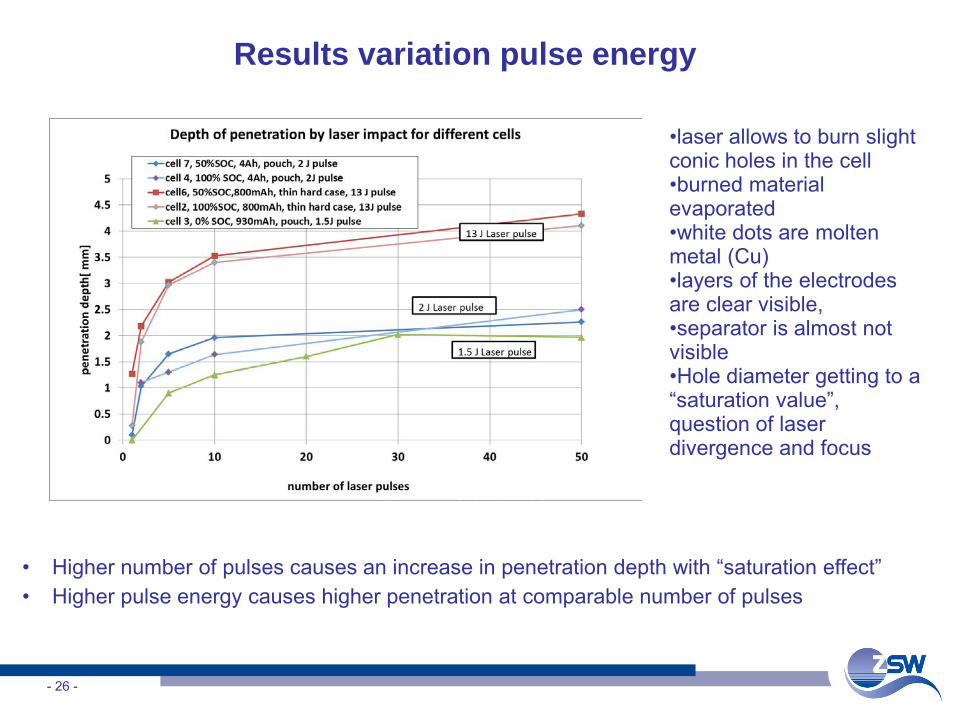
Results variation pulse energy
- 26 -
• Higher number of pulses causes an increase in penetration depth with “saturation effect”• Higher pulse energy causes higher penetration at comparable number of pulses
•laser allows to burn slight conic holes in the cell•burned material evaporated•white dots are molten metal (Cu) •layers of the electrodes are clear visible, •separator is almost not visible •Hole diameter getting to a “saturation value”, question of laser divergence and focus
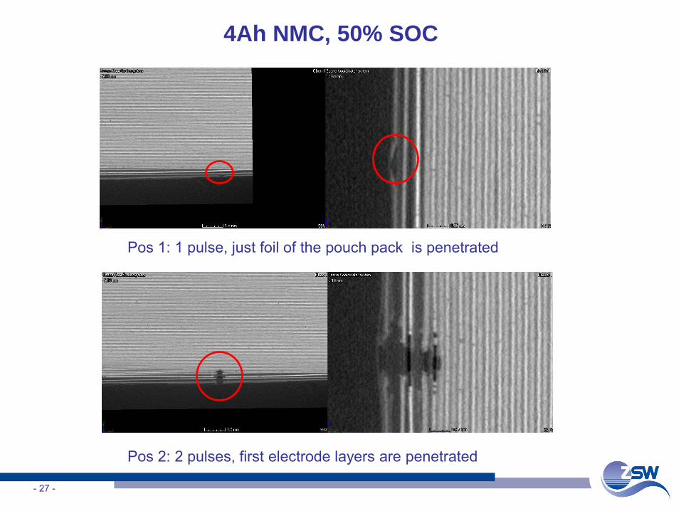
4Ah NMC, 50% SOC
- 27 -
Pos 1: 1 pulse, just foil of the pouch pack is penetrated
Pos 2: 2 pulses, first electrode layers are penetrated
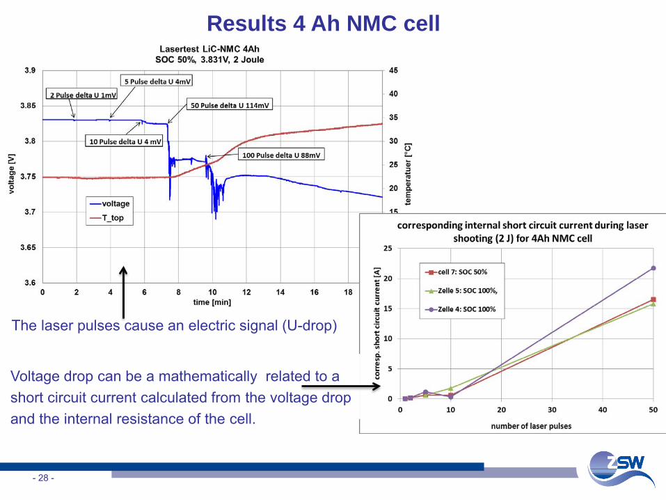
Results 4 Ah NMC cell
- 28 -
The laser pulses cause an electric signal (U-drop)
Voltage drop can be a mathematically related to a short circuit current calculated from the voltage drop and the internal resistance of the cell.
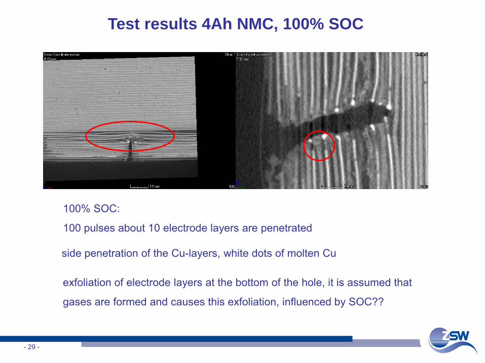
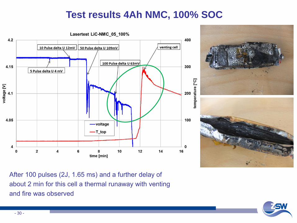
Test results 4Ah NMC, 100% SOC
- 29 -
100% SOC:
100 pulses about 10 electrode layers are penetrated
exfoliation of electrode layers at the bottom of the hole, it is assumed that
gases are formed and causes this exfoliation, influenced by SOC??
side penetration of the Cu-layers, white dots of molten Cu
Test results 4Ah NMC, 100% SOC
- 30 -
After 100 pulses (2J, 1.65 ms) and a further delay of about 2 min for this cell a thermal runaway with venting and fire was observed
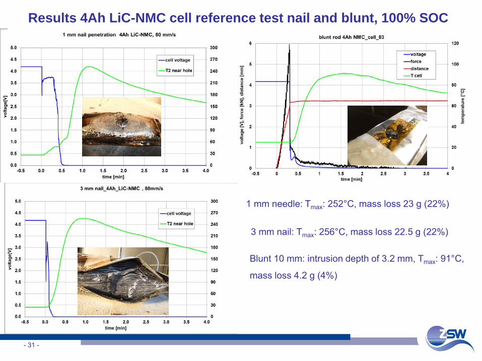
Results 4Ah LiC-NMC cell reference test nail and blunt, 100% SOC
- 31 -
3 mm nail: Tmax: 256°C, mass loss 22.5 g (22%)
1 mm needle: Tmax: 252°C, mass loss 23 g (22%)
Blunt 10 mm: intrusion depth of 3.2 mm, Tmax: 91°C,
mass loss 4.2 g (4%)
Comparison Laser impact, nail and blunt test for 4 Ah NMC cell
- 32 -
• Laser can realize very small impact
• Voltage drops are observed in different intensity related to pulse number
and intensity which might be comparable to internal short of a cell
• Laser with high intensity and high number of pulses causing permanent
moderate short circuit leading to a cell discharge
• Both nail tests (1 and 3 mm diameter) caused thermal runaway with
temperatures around 250°C
• Blunt rod test lead to a permanent internal short circuit and a energy
release comparable to an external short circuit.
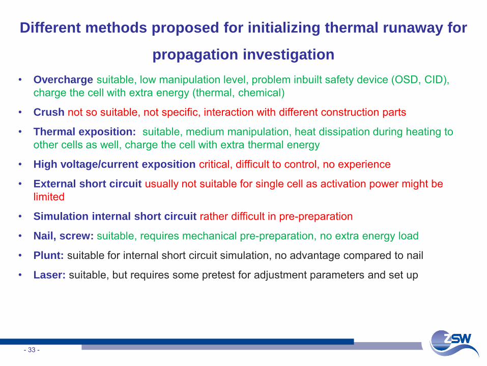
Different methods proposed for initializing thermal runaway for
propagation investigation• Overcharge suitable, low manipulation level, problem inbuilt safety device (OSD, CID),
charge the cell with extra energy (thermal, chemical)
• Crush not so suitable, not specific, interaction with different construction parts
• Thermal exposition: suitable, medium manipulation, heat dissipation during heating to other cells as well, charge the cell with extra thermal energy
• High voltage/current exposition critical, difficult to control, no experience
• External short circuit usually not suitable for single cell as activation power might be limited
• Simulation internal short circuit rather difficult in pre-preparation
• Nail, screw: suitable, requires mechanical pre-preparation, no extra energy load
• Plunt: suitable for internal short circuit simulation, no advantage compared to nail
• Laser: suitable, but requires some pretest for adjustment parameters and set up
- 33 -
Acknowledgement
• Team electrochemical accumulators, group abuse testing
• Daimler research center for financial support for the laser investigation
• German ministry of science and education within the SPEISI project
registered under 0325742C
- 34 -
Thank you for your attention !!


