1 Initiation and growth of a hydraulic fracture from a circular wellbore X. Zhang 1 , R. G. Jeffrey 1 , A. P. Bunger 1 and M. Thiercelin 2 1 CSIRO Earth Science and Resource Engineering, Private Bag 10, Clayton South, VIC 3169, Australia 2 Schlumberger RTC-Unconventional Gas, 14131 Midway Road, Suite 700, Addison, TX-75001, USA Submitted to Int. J. Rock Mech. Min. Sci. Abstract A two-dimensional (2D) model is presented for initiation and growth of one or more hydraulic fractures from a well that is aligned with either the maximum or intermediate principal in-situ stress. The coupling of fluid flow and rock deformation plays a key role in reorientation and pattern evolution of the fractures formed. After fracture initiation, the fracture can reorient as it extends from the wellbore until it becomes aligned with the preferred direction for fracture growth relative to the far-field stresses. Initiation and growth of multiple fractures are considered to study their interaction and competition with each other. In such cases, some fractures are unable to extend at all or they arrest after some limited growth, but others can grow in length relative to earlier developed fractures. For fractures that are driven by a uniformly distributed internal pressure, which implies injection of an inviscid fluid, fracture closure may occur at the portion of the fracture path adjacent to the wellbore. This local fracture closure does not typically occur when fluid viscous dissipation is introduced, but the local width is greatly reduced and a fluid lag zone develops. The reduced fracture width results in fluid viscous friction and an associated pressure drop near the wellbore, which makes fracture stimulation more expensive and less successful and may reduce well productivity. Initiation of a fracture using a viscous fluid and a higher injection rate causes the fracture to curve more gradually as it seeks to align with the maximum principal stress direction, a result from our model that is consistent with widely used tortuosity remedy methods. A dimensionless parameter is developed that is shown to characterise near wellbore reorientation and curving of hydraulic fractures driven by viscous
Transcript
1
Initiation and growth of a hydraulic fracture from a circular
wellbore
X. Zhang1, R. G. Jeffrey1, A. P. Bunger1 and M. Thiercelin2 1 CSIRO Earth Science and Resource Engineering, Private Bag 10, Clayton South, VIC 3169,
Australia 2 Schlumberger RTC-Unconventional Gas, 14131 Midway Road, Suite 700, Addison, TX-75001,
USA
Submitted to Int. J. Rock Mech. Min. Sci.
Abstract
A two-dimensional (2D) model is presented for initiation and growth of one or more hydraulic
fractures from a well that is aligned with either the maximum or intermediate principal in-situ
stress. The coupling of fluid flow and rock deformation plays a key role in reorientation and
pattern evolution of the fractures formed. After fracture initiation, the fracture can reorient as it
extends from the wellbore until it becomes aligned with the preferred direction for fracture
growth relative to the far-field stresses. Initiation and growth of multiple fractures are considered
to study their interaction and competition with each other. In such cases, some fractures are
unable to extend at all or they arrest after some limited growth, but others can grow in length
relative to earlier developed fractures. For fractures that are driven by a uniformly distributed
internal pressure, which implies injection of an inviscid fluid, fracture closure may occur at the
portion of the fracture path adjacent to the wellbore. This local fracture closure does not typically
occur when fluid viscous dissipation is introduced, but the local width is greatly reduced and a
fluid lag zone develops. The reduced fracture width results in fluid viscous friction and an
associated pressure drop near the wellbore, which makes fracture stimulation more expensive
and less successful and may reduce well productivity. Initiation of a fracture using a viscous
fluid and a higher injection rate causes the fracture to curve more gradually as it seeks to align
with the maximum principal stress direction, a result from our model that is consistent with
widely used tortuosity remedy methods. A dimensionless parameter is developed that is shown to
characterise near wellbore reorientation and curving of hydraulic fractures driven by viscous
2
fluid. For complex multiple fracture cases, the results demonstrate that the misalignment angle
and the number of initiated fractures are important in near-well fracture path selection.
Introduction
One primary role of hydraulic fracturing is to provide a high conductivity pathway along
which reservoir fluids can flow to the well. However, the development of the fractures and,
ultimately, the treatment effectiveness, depends on the evolution of the fracture path in the near-
wellbore region. Near the wellbore multiple subparallel fractures may be generated because of
fracture initiation, either from perforations positioned along and phased around the wellbore or
from natural flaws around the open hole. Perforations and flaws are not usually aligned with the
far-field stress direction. Fractures initiated from these defects will reorient themselves to a plane
perpendicular to the minimum far-field stress direction as they grow away from the wellbore
(Hamison and Fairhurst, 1970; Daneshy, 1973; El Rabaa, 1989; Weng, 1993; Soliman et al.
2008). The reorientation process gives rise to mode II and mode III stress intensity factors along
the fracture leading edge, which has been shown to produce fracture branching and
segmentation, in addition to curving (Daneshy, 1973; Pollard et al., 1982; Hallam and Last,
1990, Soliman et al. 2008). The overall result of such a fracture initiation process is the
generation of near-wellbore fracture tortuosity. As a consequence, the net pressure required to
extend the fractures is increased considerably. Methods to reduce near-wellbore tortuosity and
potential proppant placement problems have been developed that involve using higher viscosity
fluids and higher injection rates to initiate the fracture. Proppant slugs and oriented perforations
are also used in an effort to reduce the fracture complexity. In many naturally fractured
formations (coal seams, naturally fractured reservoirs and geothermal reservoirs), near-wellbore
tortuosity can lead to serious problems that significantly affect the success of hydraulic fracture
stimulation treatments (Cuderman et al., 1986; Chu et al., 1987; Chen, 2009). Methods to avoid
or reduce fracture tortuosity are therefore important. When the source of the tortuosity is
understood, methods to avoid its development can be designed. For example, Manrique and
Venkitaraman (2001) showed results demonstrating that, in wells where otherwise failed
treatments occurred, perforations oriented in the plane of the maximum principal stress direction
are an effective method of eliminating tortuosity and avoiding initiation of multiple fractures. We
present results that quantify the effect of treatment parameters and rock properties on the
development of near-wellbore fracture curvature. These results allow the engineer to design
improved breakdown methods to minimise the development of fracture tortuosity.
3
Hydraulic fracture initiation from a wellbore has been studied theoretically and
numerically, but still remains a subject of interest for petroleum industry research. In particular,
many details of how non-planar fracture geometries contribute to high treating pressures, often
observed in the field, are still lacking. The models should capture pressure loss in the small zone
associated with near-wellbore fracture tortuosity. Generation of near-wellbore fracture
complexity, with associated pinching and competition between multiple fracture branches can
occur simultaneously in the evolution of fracture paths. Daneshy (1973) considered the
conditions for fracture initiation and propagation from vertical and deviated wellbores to find
factors controlling near-wellbore effects. Narendran and Cleary (1983) used numerical methods
to analyse curving and interaction of multiple fractures. Weng (1993) and Yew et al. (1993)
numerically studied the interaction and linkage of multiple fractures in stress fields around a
deviated well, including fracture growth in a plane inclined to the wellbore axis. A finite-element
model for a wellbore and a single bi-wing fracture was presented by Cherny et al. (2009) with a
predetermined fracture trajectory. A quasi-static approach was used by them, as is the case for
most previous studies, and only stationary crack problems were studied, using different fixed
fracture lengths. In their paper, the fracture curving is predetermined to follow an arc with a
given radius. Although narrow fracture width in the near-wellbore region and abnormal fluid
pressure is predicted by their numerical modelling, the predetermined fracture path limits the
application of the results obtained. Moreover, asymmetric multiple fractures are commonly
observed in the field and in laboratory experiments (Rabaa, 1989; Hallam and Last, 1990; Yew
et al., 1993; Weng, 1993].
Numerical hydraulic fracturing models have been applied to the study of problems dealing
with competing fracture growth, including width reduction and associated increased viscous
frictional pressure loss. Based on such numerical analyses, various operational remedial
techniques have been proposed to overcome the near-wellbore effects, such as using higher
injection rate, higher viscosity fluids to reduce tortuosity and oriented perforations to control
fracture initiation orientation (Manrique and Venkitaraman, 2001; Abass, et al., 2009). In
particular, the fracture turning processes, during which the fracture reorients as it grows from a
wellbore to become perpendicular to the minimum principal stress direction, is the focus of this
paper. We recognized that the fracture turning can induce rotation of local principal stresses. The
curving fractures studied here are likely to be less smooth than modelled and may break up into
echelon cracks near the wellbore, as discussed by Pollard et al. (1982). However, formation of
segmented and echelon fractures is beyond the scope of this study, in which we focus on
formation of 2D, smoothly curving fractures.
4
In this paper, we will employ a 2D numerical method that can model hydraulic fracture
growth from a wellbore. The 2D plane strain assumption, used here, is justified if the height,
along the wellbore axis direction, of a slot or natural flaw, which is the site of initiation of the
hydraulic fracture, is relatively large compared to its radial depth. In addition, the wellbore axis
is assumed to be aligned with the maximum or intermediate principal stress direction and axial
longitudinal fractures would be created. In the following, we will first present comparisons to
published results to verify our model and then we will present results related to initiation and
propagation of single and multiple hydraulic fractures from the wellbore. The advantage of our
model is that it can explicitly address the coupling of rock deformation and viscous fluid flow
(Zhang et al., 2005, 2007, 2008, 2009). Energy dissipation related to viscous flow is important
for predicting hydraulic fracture propagation from flaws located along the wellbore wall. By
including viscous flow in the model, narrow portions of the fracture channel which arise from the
fracture curving and interactions with the wellbore, naturally lead to higher pressures and
pressure gradients. This non-uniform pressure distribution is shown to have a strong effect on the
fracture curving and overall path. Most previous studies assume the fluid has zero viscosity,
which leads to a uniform pressure that does not depend on the fracture channel width
distribution.
First we consider a single hydraulic fracture growing from a circular wellbore and develop
a nondimensional parameter whose value can be related to the fracture path. Next we study the
curvature of two or more fractures growing from the wellbore, to validate the proposed
dimensionless parameter. We vary the locations of the starter fractures and show how this affects
the hydraulic fracture growth path. We contrast these results with published results that used,
instead, a pre-determined fracture path. In general, the fracture path depends on the detailed
pressure and width distribution that arises from solution of the coupled problem, including the
non-planar fractures interacting with themselves, with the wellbore, and with other hydraulic
fractures. The solution provides, at each time step, the fracture path and opening and excess
pressure distributions. Although the model considers only 2D fractures, the results presented
provide useful insights into the formation and interaction of fracture propagation patterns in the
presence of a wellbore.
Problem Formulation
The 2D hydraulic fracture problem that we consider in this paper is shown in Fig. 1, which
represents a cross-section through a vertical well that is aligned with the maximum or
intermediate principal stress. Two flaws like perforated or abrasively jetted slots, serve as
5
initiation sites for the longitudinal hydraulic fractures that are driven by injected fluids. If the
perforated interval is long, or if the well is not cemented and cased, these axial longitudinal
fractures and their propagation within the transverse plane, as shown in Fig. 1, is assumed to be
independent of the fracture height and subject to plane-strain conditions. Deviation from the
direction of maximum tensile stress would cause the fractures to reorient themselves to form bi-
wing fractures, as depicted in Fig. 1. Of course, more than two fractures at different angles may
initiate in a homogeneous rock instead of just a single bi-wing fracture.
For the sake of simplicity, the in-situ stress field is given as in Fig. 1 based on the in-plane
maximum H and minimum h principal stresses. The rock is assumed to be impermeable and
the stresses can be considered as total far-field stress values. The well radius is denoted as R and
the initial fracture length L (which is shown exaggerated in Fig. 1) is assumed to be very small so
that the effect of initial fracture length on final fracture path can be neglected. Each fracture is
labeled by its initiation orientation angle with the respect to the x-axis, which is the in-plane
maximum principal stress direction. Fractures that initiate at =0 would propagate as straight
planar fractures along the x-axis direction. The well radius is chosen as 0.1 m for the cases
considered in this paper. The wellbore pressure is denoted as wP , which will be determines as
part of the solution. It should be noted that the wellbore pressure is the same as the entrance
pressure for each fracture.
The properties of the rock, fluid and fractures are as follows. The elastic properties for the
intact rock are Young’s modulus (E), Poisson’s ratio ( ) and the mode I fracture toughness
( ICK ). The injected fluid is incompressible and has a Newtonian dynamic viscosity given by .
The sum of all injection rates of fracture branches growing from the well is assumed to be
constant and is denoted as inQ . Although the total rate injected, inQ , is specified as constant, the
rate into each fracture can be different and can vary with time to allow for different growth rates
of each fracture.
Near the wellbore, the two sides of a fracture may come into contact. The model allows for
contact stresses to develop and uses a cohesionless Coulomb friction criterion to assess the
frictional strength of surfaces in contact, (Jaeger et al., 2007)
( )n fp (1)
where is the shear stress along the closed fractures, n is the normal stress acting across them,
fp is the fluid pressure and is the coefficient of friction.
6
In addition to the tangential displacement discontinuity (DD), v, associated with frictional
slip along the closed fracture segments or shear displacement in general, there exists opening
displacement w along the opened hydraulic fractures, which contributes to fracture conductivity.
All of these elastic and plastic displacements give rise to changes in the rock stress or changes in
the tractions acting along the fracture surfaces. The governing equations for stresses, fluid
pressure and displacements are given in Zhang et al. (2007, 2009), and are given in terms of
Green’s functions. We employ the displacement discontinuity method (DDM) (Crouch and
Starfield, 1990) for the simulation of rock deformation in a 2D homogeneous and isotropic
elastic material, on which a uniform stress (e.g. H does not vary with y) is applied at infinity.
The governing equations for fluid flow in the fracture channel are given by Zhang et al.
(2009). There are two types of fluid movement along fractures. The fluid can diffuse along the
closed fractures without any mechanical opening of the fracture, or it can flow through an open
channel as a result of opening mode hydraulic fracturing processes. In the latter case, the fluid
pressure is balanced by the compressive stress caused by in situ stress and rock deformation, that
is, n fp . We use Reynolds’ equation to describe fluid movement inside the opened hydraulic
fractures:
3( ) ( ) in which fpw q w
qt s s
(2)
where w is the mechanical opening and vanishes for the closed segments, is the pre-existing
hydraulic aperture arising from surface roughness and microstructures, s is a distance measured
along the fracture length, q is the fluid flux and 12 .
However, it must be mentioned that effective stress changes in the fluid-infiltrated and
pressurised fracture portion can produce changes of the hydraulic aperture without fully opening
a fracture (Walsh and Grosenbaugh, 1979; Witherspoon et al., 1980; Brown and Scholz, 1986).
The dilatation can slightly affect the internal pressure distributions since the resulting fluid
conductivity varies in location and time. As stated above, the hydraulic aperture at the beginning
is assigned with an initial value 0w for each closed fracture segment. The evolution of obeys
a nonlinear spring model in response to any increments of the internal pressure. In particular, the
equation governing the hydraulic aperture change associated with pressure change is given as
follows,
fdPd / (3)
where is a small constant with a value of 810 /MPa in the model. A pressure diffusion
7
equation is applied to calculate the pressure inside a closed natural fracture (Zhang et al., 2009)
0)( 2
s
p
sc
t
p ff (4)
where )12/(1 c . The associated flow rate can be obtained by Darcy’s law. This calculation
applies to all closed portions of fractures, whether they are undergoing or have undergone slip or
not.
To complete the problem formulation, we need boundary and initial conditions for the
above governing equations. At the beginning, all fracture segments are assumed to be evacuated
and the rock mass is stationary. A rock failure criterion is needed, as is a method for handling
fracture intersection and associated fluid flux redistribution. For the fractures connected to the
wellbore, the sum of the fluid flux entering them is equal to the injection rate and the fluid
pressure continuity is enforced, that is,
1
(0, ) and (0, )N
ii in f w
i
q t Q p t P
(5)
where N is the number of starter fractures and (0, )iq t the fluid volumetric flux into a fracture i
and (0, )ifp t is the fluid pressure at the mouth of the fracture.
At the fracture tip, the opening and shearing DDs are zero, that is,
0)()( lvlw (6)
and the fracture opening profile near the crack tip possesses a square root shape with distance
from the tip as predicted by Linear Elastic Fracture Mechanics (LEFM) theory. The method
presented here approximates the viscosity dominated hydraulic fracture tip conditions where
energy dissipated in fluid transport becomes much larger than fracture energy (Detournay, 2004;
Bunger and Detournay, 2008), by an approach that explicitly calculates the fluid lag size and
relies on discretization to capture rapid changes in fluid pressure near the tip.
When the stress intensity factor at the fracture tip reaches the fracture toughness of the
rock, fracture growth occurs. In general, the fracture propagation direction may change as
dictated by the near-tip stress field characterised by the Stress Intensity Factors (SIFs). In
particular, the mixed-mode fracture criterion proposed by Erdogan and Sih (1963) is used for
determining fracture growth direction in the model. This same approach has been used by a
number of researchers (e.g. Mogilevskaya et al. 2000b). It must be noted that the calculated
crack deflection angle varies strongly at the near-well region. To smooth the fracture pathways, a
relaxation method is used in reducing the possibility in creating zig-zaging paths. In particular, if
8
the crack deflection angles for two consecutive growth steps have different sign, the new angle is
reduced by the relaxation factor.
Numerical Scheme and Verification
The coupled fluid flow (to obtain pressure) and rock deformation (to obtain fracture
opening) problem is solved in an implicit manner by incorporating the elasticity equation into the
Reynolds equation. The responses obtained are history dependent because of the irreversible
fluid flow and frictional sliding processes. Additionally, there are three moving fronts inherent in
the problem, namely the slip front, the fluid front and the fracture opening (crack tip) front. The
reader is referred to Zhang et al. (2007, 2009) for a detailed description of the numerical solution
methods applied in modelling these processes. At the wellbore, the fracture entry pressures must
be equal to the wellbore pressure. This condition is enforced through an iteration scheme. The
fracture entry and wellbore pressures are constrained to be equal by enforcing Eqn. (5). The
injection rate into each fracture is found based on the specified current wellbore pressure, using
the method described in our previous work applied to fracture junctions (Zhang et al., 2007). In
the calculation, the convergence of the solution is very sensitive to the time step and the
convergence error tolerance. To rapidly find a converged wellbore pressure, a relaxation factor is
used in updating the wellbore pressure at each iteration step. A tolerance (< 410 ) is set for the
relative error between the wellbore and fracture entry pressures. Therefore, in the program, a
new iteration loop is introduced for obtaining a converged wellbore and fracture entry pressure
solution.
The numerical method has been verified, in our previous papers, by comparison to
published solutions to a range of problems; see Zhang and Jeffrey (2009). However, to treat
problems that include a wellbore, the program was modified to allow correct treatment of the
interior and exterior problems generated when the wellbore is discretized using the DD
(Displacement Discontinuity) method. The resulting DDs along the wellbore boundary are
fictitious, although they are necessary for calculating pressure and displacement at the wellbore
wall and along the fractures. The fictitious DDs do not have a literal physical interpretation as
DDs, but rather are an approach to imposing the correct pressure condition at the wellbore
boundary. Moreover, the interior wellbore disc, if not constrained, is free to move as a rigid body
and therefore the rigid body motion of the disc must be suppressed when applying a DDM to
such problems (Crouch and Starfield, 1983).
A simple method to suppress these rigid-body motions is as follows. Two additional
9
elements are defined inside the wellbore and assigned fictitious DDs. Then we calculate the
displacement on the negative side of an element based on the fundamental elastic solutions
(Crouch and Starfield, 1983). After that, the four displacements at these two additional elements
are set to zero in order to construct a closed, well-posed problem for all DDs. The displacements
on the negative side of the elements are reproduced here as given by Crouch and Starfield (1983,
Eqn. 5.6.1) for both normal and tangential displacement components.
The elasticity equations for the normal and tangential DDs ( ku includes w and v.) at the
middle of each element of the system are
,ijk k f ij ijK u P k n s along the wellbore and the fractures (7)
0 ,ijk kM u k n s for the two additional elements (8)
where ijkK and ijkM are the coefficient matrices derived from the fundamental elastic solution as
is done in conventional boundary element methods (see details in Crouch and Starfield, 1983);
and ij are the resultant stresses along the fracture surface arising from far-field (in situ) stresses.
Here, Eqn (7) enforces equilibrium at DD elements along the fractures and the wellbore, and Eqn
(8) enforces the constraint condition that eliminates rigid body motion of the interior disc by
requiring zero displacements at two additional interior elements. The above simultaneous
equations (Eqns (7) and (8)) are solved for normal and shear DDs of all elements along the
wellbore, the fractures and of the two additional elements, once the fluid pressure is known. The
DDs that are obtained can then be used to calculate stress or displacement at any other point
inside the rock mass. It must be mentioned that the additional discretization along the wellbore
can slow down the computation speed and requires more intense calculation. Moreover, it is
found that the model is not efficient to treated extremely high injection rate and fluid viscosity
problems since the fracture path is very sensitive to the wellbore pressure development.
Figure 2 displays the comparisons in terms of normalised stress intensity factors (SIFs) for
two symmetric cracks emanating from a wellbore under different loading conditions. Both
fractures are of equal length and the loading conditions are illustrated in inset drawings. These
two cases have been thoroughly studied by Newman (1971), Atkinson and Thiercelin (1993) and
Mogilevskaya et al. (2000a). These papers all show very similar results for this problem so we,
therefore, only use the results obtained by Newman (1971) as the reference values. In Fig. 2, our
computed numerical results provide a good approximation to those obtained by Newman (1971).
The small differences that still exist have a maximum relative error of less than 5 precent for the
data in Fig. 2. Considering the sensitivity of SIF to element size, the results are taken as
10
acceptable.
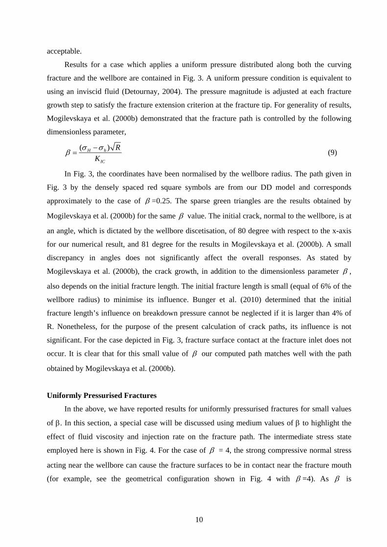
Results for a case which applies a uniform pressure distributed along both the curving
fracture and the wellbore are contained in Fig. 3. A uniform pressure condition is equivalent to
using an inviscid fluid (Detournay, 2004). The pressure magnitude is adjusted at each fracture
growth step to satisfy the fracture extension criterion at the fracture tip. For generality of results,
Mogilevskaya et al. (2000b) demonstrated that the fracture path is controlled by the following
dimensionless parameter,
( )H h
IC
R
K
(9)
In Fig. 3, the coordinates have been normalised by the wellbore radius. The path given in
Fig. 3 by the densely spaced red square symbols are from our DD model and corresponds
approximately to the case of =0.25. The sparse green triangles are the results obtained by
Mogilevskaya et al. (2000b) for the same value. The initial crack, normal to the wellbore, is at
an angle, which is dictated by the wellbore discetisation, of 80 degree with respect to the x-axis
for our numerical result, and 81 degree for the results in Mogilevskaya et al. (2000b). A small
discrepancy in angles does not significantly affect the overall responses. As stated by
Mogilevskaya et al. (2000b), the crack growth, in addition to the dimensionless parameter ,
also depends on the initial fracture length. The initial fracture length is small (equal of 6% of the
wellbore radius) to minimise its influence. Bunger et al. (2010) determined that the initial
fracture length’s influence on breakdown pressure cannot be neglected if it is larger than 4% of
R. Nonetheless, for the purpose of the present calculation of crack paths, its influence is not
significant. For the case depicted in Fig. 3, fracture surface contact at the fracture inlet does not
occur. It is clear that for this small value of our computed path matches well with the path
obtained by Mogilevskaya et al. (2000b).
Uniformly Pressurised Fractures
In the above, we have reported results for uniformly pressurised fractures for small values
of . In this section, a special case will be discussed using medium values of to highlight the
effect of fluid viscosity and injection rate on the fracture path. The intermediate stress state
employed here is shown in Fig. 4. For the case of = 4, the strong compressive normal stress
acting near the wellbore can cause the fracture surfaces to be in contact near the fracture mouth
(for example, see the geometrical configuration shown in Fig. 4 with =4). As is
11
proportional to the difference between H and h , the larger this difference, the stronger the
tendency for pinching of the fracture. The same conclusion has been drawn by Cherny et al.
(2009). The opening DD distributions are displayed in Fig. 4, too, and the area with zero opening
DD corresponds to the contact zone. However, such contact conditions were not taken into
account in Mogilevskaya et al. (2000b) and, instead, this portion of the fracture was allowed to
overlap in their model. In Fig. 4(a), the purple line shows our results without any contact
constraint. The crack path without the surface contact restriction follows the trajectory obtained
by Mogilevskaya et al. (2000b), although there is some small discrepancy between two curves.
We checked if this was caused by the different initial fracture lengths. However, changing the
initial flaw length did not affect the results or the path away from the wellbore. In the
calculations, we have already adopted a very fine mesh and we did not see any crack path
zigzagging for this case.
More importantly, from the results shown in Fig.4, it is clear that the surface contact, or
lack of it, plays an important role in fracture development around a wellbore. The fracture
trajectory with contact is less curved and does not approach the y-axis, running through the
center of the wellbore, as rapidly as the results from Mogilevskaya et al. (2000b). Compared with
the results in Fig. 4(a), the fracture offset relative to the horizontal centreline is clearly larger if
contact is taken into account. Also, applying a coefficient of friction, , to the contacting
surfaces can increase this offset a little bit more as shown in Fig. 4(b). The narrow fracture
opening channel near the wellbore will directly increase the fluid injection impedance, increasing
the injection pressure and making it more difficult to carry out the fracture treatment. Hence the
contact stresses near the wellbore, even though the contact area is relatively small compared with
the whole fracture, can significantly affect the fracture growth and pressure. Generally speaking,
the fracture trajectories for uniformly pressurised crack pathways are determined by the values of
both and , but they are more sensitive to than to .
Effects of Fluid Viscosity
In the above section, all fractures are assumed to be uniformly pressurised as implied by a
toughness dominated condition. This is not the case in general for hydraulic fractures. Viscous
dissipation arising from the fluid flowing in the fracture channel is typically very important. The
viscous fluid flow will result in a pressure gradient along the fracture length and the non-constant
pressure distribution leads to different fracture opening. For example, contact between the two
sides of the fracture as discussed above, become much less likely when viscous flow is
12
considered. The resulting pressure distribution is strongly affected by narrow sections of the flow
path, such as those that develop near segments that come into contact for the uniform pressure
cases. For the modelling undertaken here, we do not considered the fluid compressibility and the
fluid volume change caused by changes in wellbore pressure and shape. A constant total
injection rate is specified for fluid flow into the wellbore. In addition, a small initial fracture size
(6% of wellbore radius) is used as a starting point for all fractures emanating from the wellbore.
The effect of different initial fracture lengths is thus not considered in this paper. Therefore, our
model fully accounts for the effect of the wellbore on stress field changes, but it does not fully
account for the effect of the wellbore on the fluid flow (from compressibility induced flow
during the fracture initiation process, for example, when pressure is changing rapidly). For an
injection rate of 0.0004 m2/s, for instances, if the fracture height is 1 m, the given injection rate is
equivalent to 24 litres per minute.
1. Single fracture cases
For this particular case, we employed the following material parameters: Young’s modulus
E= 50 GPa, ICK =1.0 MPa m . Under the same far-field stress conditions and the
geometric setting as given in Fig. 4, the hydraulic fracture path is found using a fluid viscosity
=0.01 Pa s and an injection rate of 0.0004 m2/s. The initial fracture angle is 80 degrees with
respect to the positive x-axis. For these conditions, a significant pressure gradient is generated
along the fracture path as shown in Fig. 5(b). The fluid pressure at the fracture mouth is over 20
MPa. This large wellbore pressure induces tensile hoop stress along the boundary of the
wellbore. The large fluid pressure is not only the driving force for crack growth, but is also a
factor in preventing fracture contact at the fracture entry. This lack of contact is indicated in Fig.
5(a) by the non-zero DDs everywhere along the fracture. The fracture opening in the portion
adjacent to wellbore is, however, very small, although a high pressure exists there. As the
hydraulic fracture grows in length, the near-wellbore fracture width increases and we expect that
proppant could then be placed through the restricted near wellbore width.
The fully opened fracture case, with no fracture contact occurring near the wellbore,
generates a fracture path with less curvature developing as the fracture propagates away from the
wellbore, in contrast to the more curved fractures for uniform pressure case shown in Fig. 4.
When viscous fluid flow is included, the fracture turning radius increases and the opening
distribution become smoother. This result supports the use of high viscosity fluid for initiation of
hydraulic fractures as a means of reducing fracture tortuosity (curvature in this case). Although
13
eventually the fracture becomes aligned in the direction of the maximum principal stress, the
injection pressure cannot decrease below a level sufficient to keep the whole fracture open (e.g.
otherwise a pinching point may develop near the wellbore). Incipient pinching at the wellbore
will result in elevation of the pressure, which would in turn prevent the pinch from developing.
Thus, use of more viscous fluids can produce a less curved fracture but continued propagation of
these fractures will still require elevated injection pressures when compared to the propagation
pressure for a straight planar fracture.
The wellbore pressure will increase, when a constant injection rate is imposed, until the
fracture is opened and propagated. The pressure will increase more slowly and eventually
decrease as the plane strain 2D fracture grows to become long in size compared to the wellbore
diameter. The non-planar nature of the fracture path and the associated restriction in fracture
width in the portion near the wellbore causes the wellbore pressure to remain at a higher level,
compared with the pressure to extend a planar fracture. The interaction between higher wellbore
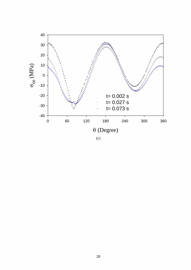
pressure and in-situ stresses can generate a larger tensile hoop stress along the x-axis direction,
as shown in Fig. 5(c). We note that the hoop stress at the point on the x-axis nearly perpendicular
to the crack initiation site is tensile (positive), as shown in Fig. 5(c). The wellbore may thus
break down again, in a direction parallel to the x axis (the maximum in-situ stress direction), if a
critical stress level is reached for this point. The curved fracture would then likely stop growing
since the pressure to extend the favourably oriented fracture would be considerably lower.
Moreover, a fluid lag zone can be seen near the tip of the curved fracture shown in Figs.
5(b) and 5(d). The lag is a small region near the tip that is open but not pressurised by the fluid.
The existence of a fluid lag, in this case, reflects a larger pressure gradient, which can cause the
fracture physical tip to grow beyond the fluid front and is an important feature of viscous fluid-
driven fracture growth. Also, the lag zone appears to expand with the fracture growth since it is
smaller at the earlier time shown in Fig. 5(d).
To characterize the effect of fluid viscous dissipation on fracture paths, we introduce
another parameter which provides an apparent fracture toughness arising from viscous
dissipation, as given in Jeffrey(1989), based on an earlier somewhat different formulation given
by Settari and Price (1984), and Detournay (2004) in the case of zero lag. This apparent
toughness, when substituted for the rock fracture toughness in Eqn. 9 provides a dimensionless
parameter, given by Eqn. 10, that we hypothesize will control the curving of a hydraulic fracture
driven by viscous fluid as it grows from a wellbore.
14
3 1/4
( )
( )H h
Fin
R
Q E
(10)
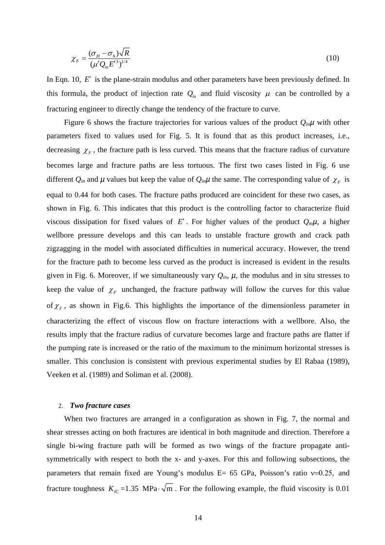
In Eqn. 10, E is the plane-strain modulus and other parameters have been previously defined. In
this formula, the product of injection rate inQ and fluid viscosity can be controlled by a
fracturing engineer to directly change the tendency of the fracture to curve.
Figure 6 shows the fracture trajectories for various values of the product Qinµ with other
parameters fixed to values used for Fig. 5. It is found that as this product increases, i.e.,
decreasing F , the fracture path is less curved. This means that the fracture radius of curvature
becomes large and fracture paths are less tortuous. The first two cases listed in Fig. 6 use
different Qin and µ values but keep the value of Qinµ the same. The corresponding value of F is
equal to 0.44 for both cases. The fracture paths produced are coincident for these two cases, as
shown in Fig. 6. This indicates that this product is the controlling factor to characterize fluid
viscous dissipation for fixed values of E . For higher values of the product Qmµ, a higher
wellbore pressure develops and this can leads to unstable fracture growth and crack path
zigzagging in the model with associated difficulties in numerical accuracy. However, the trend
for the fracture path to become less curved as the product is increased is evident in the results
given in Fig. 6. Moreover, if we simultaneously vary Qin, µ, the modulus and in situ stresses to
keep the value of F unchanged, the fracture pathway will follow the curves for this value
of F , as shown in Fig.6. This highlights the importance of the dimensionless parameter in
characterizing the effect of viscous flow on fracture interactions with a wellbore. Also, the
results imply that the fracture radius of curvature becomes large and fracture paths are flatter if
the pumping rate is increased or the ratio of the maximum to the minimum horizontal stresses is
smaller. This conclusion is consistent with previous experimental studies by El Rabaa (1989),
Veeken et al. (1989) and Soliman et al. (2008).
2. Two fracture cases
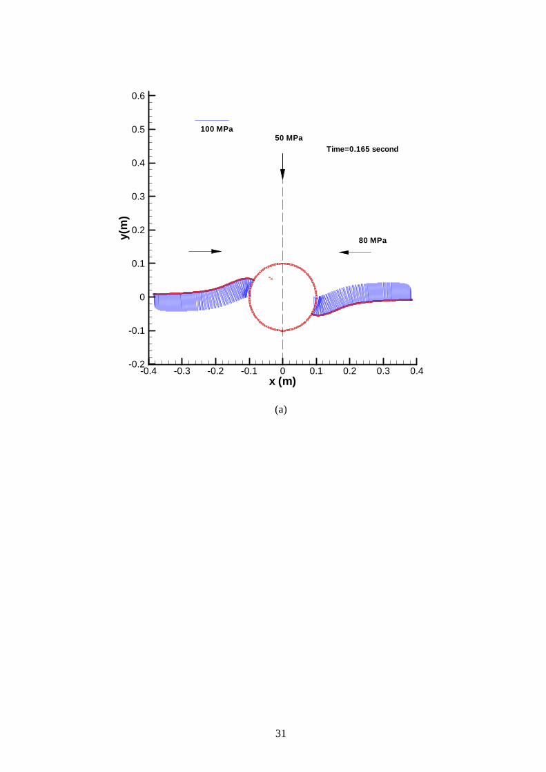
When two fractures are arranged in a configuration as shown in Fig. 7, the normal and
shear stresses acting on both fractures are identical in both magnitude and direction. Therefore a
single bi-wing fracture path will be formed as two wings of the fracture propagate anti-
symmetrically with respect to both the x- and y-axes. For this and following subsections, the
parameters that remain fixed are Young’s modulus E= 65 GPa, Poisson’s ratio and
fracture toughness ICK =1.35 MPa m . For the following example, the fluid viscosity is 0.01
15
Pa s and the injection rate is 0.0004 m2/s. The alignment angle is 150° and 330° for both
fractures in Fig. 7(a) and 120° and 300° for the case shown in Fig. 7(b). The former case is called
as low-angle case since the interior angle between the fracture and the horizontal stress is 30°,
while the latter is called a high-angle case with an interior angle of 60°. The far-field stresses are
increased to 50 and 80 MPa for the in-plane vertical and horizontal principal stresses,
respectively. The fracture path is different for the two cases shown with the low-angle fractures
in Fig. 7(a) growing back toward the centre line of the wellbore. The two fracture wings tend to
eventually both grow parallel and along the centreline at y=0, while for the high-angle fractures
in Fig. 7(b), there is an offset left between the two wings on either side of the wellbore, which is
about equal to the wellbore diameter. The fracture growth path generated by the high-angle
fractures resembles the fracture geometry used by Weng (1993) and Cherny et al. (2009).
The net wellbore pressure, which is the difference between the wellbore pressure and the
far-field minimum principal stress, is initially over 40 MPa for the high-angle case shown in Fig.
7(c) and later in time this net pressure is approximately reduced to 25 MPa. This very large net
pressure arises because of the growth of the fracture with an orientation not aligned
perpendicular to the minimum stress and because of the restriction in fracture width near the
wellbore resulting from the interaction of the fracture with the wellbore. An increase in the
initiation angle results in an increase in the injection pressure. There is a strong pressure drop
post fracture initiation, after which the wellbore pressure tends to be more constant with a slight
increasing trend. The pressure is maintained at a higher level throughout the short time
simulated. However, if we compare the fluid pressure distribution along the fractures at the same
time for two different initiation angles as shown in Fig. 7(a) and (b), the pressure level along
most of the fracture extent is the same. The strong pressure drop occurs only in the vicinity of the
wellbore, and is associated with the local fracture width reduction there and with the higher
normal stress acting across the fracture at this location. This phenomenon of friction pressure
loss with near-wellbore localisation has been reported in Weng (1993) although different near-
wellbore fracture paths were produced by his numerical modelling, in part because he used a
uniform pressure to drive the fracture. It is reasonable to conclude that the fracture length for the
two different initial angles will be similar, too, and the fracture growth outside the zone of
influence of the wellbore appears to depend on parameters which control growth of a fracture
without a wellbore, although there is a high friction loss near the wellbore. Moreover, the
pressure in the fracture away from the wellbore is only slightly above the far-field minimum
stress magnitude as shown in Fig. 7(a) and 7(b).
16
The comparison of fracture trajectories in Fig. 7(d) further indicates that the fracture
pathways are determined by the dimensionless parameter F , for the case where viscous
dissipation is important. One can see the two pathways in Fig. 7(d) are exactly the same.
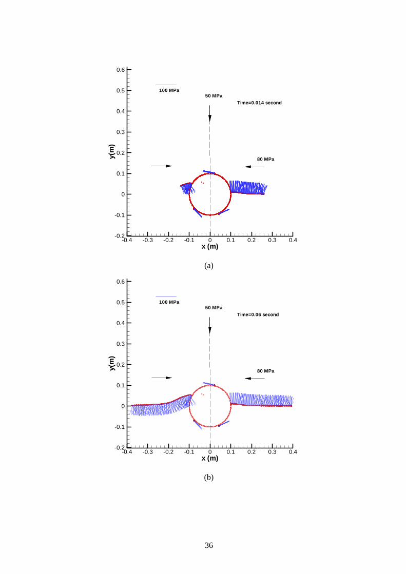
3. Multiple fracture cases
In the presence of multiple fractures, some starter fractures cannot propagate because of
local stress states at their initiation sites. The fractures subject to strong compression are
suppressed and starter fractures subject to low confinement extend. In Fig. 8, four starter
fractures are arranged every 90 degrees around the wellbore with angles of 60°, 150°, 240° and
330°. Despite the additional flaws along the wellbore, a bi-wing fracture geometry is generated
for this fracture configuration. Two of the four starter fractures grow significantly and become
dominated, while the other two fail to extend from the initial flaw when subject to the pressure in
the wellbore. Clearly, fracture initiation is sensitive to the local stress state at the site of the flaw.
The time-dependent fracture path development, as calculated by the model, is shown at two
times in Figs. 9(a) and (b) for cases that include five starter fractures with a special angular
arrangement. A single fracture is dominant at early time (Fig. 9(a)) but the pattern eventually
develops into a system with two dominant asymmetric fractures on both sides of the wellbore
shown in Fig. 9(b). The right-hand side fracture is dominant at the beginning because the stress
at this starter fracture location allows growth at a lower pressure. The left-hand side fracture,
which is in a slightly less favourable initiation direction, then starts to grow and extends to a
similar length as the right fracture, eventually. This emphasizes the interaction among two
fractures and the wellbore. When one fracture at higher internal pressure becomes longer, the
compressive stresses across other fractures, for the geometry studied, is affected in a way that
favours growth of a second fracture. In general, growth of other starter fractures may occur as a
result of the extension of one or more dominant fractures. The growth rate of the second fracture
may then increase, as demonstrated by comparing Figs. 9(a) and (b). When a second starter
fracture starts to grow, more fluid will enter this new fracture as its growth is favoured under the
current near wellbore stress field. Less fluid will then be available to extend the first or early-
growing fracture with the result that the second fracture to initiate can grow to become
approximately equal in size to the first, as shown in Fig. 9(b). After the fracture reorientation of
the newly activated fractures is completed and the second fracture has grown to a size
comparable to the wellbore diameter and to the first fracture, there will be another balance
established in fracture growth and fluid flow among these fractures all approximately aligned in
17
the preferred direction. Eventually, two dominant fractures are extended, in a fashion similar to
the single bi-wing fracture lying in the preferred direction. Therefore, a slight deviation from the
preferred direction does not greatly affect long term fracture growth. Similar fracture growth
paths, with one following the preferred direction and a secondary one turning quickly into this
direction have been found in experimental results (Abass et al., 2009).
With an increase in fluid viscosity, the fracture turning radius becomes larger as shown in
Fig. 9(c). The left-hand side fracture is reoriented in a smoother way or in a path with a lower
curvature. The path followed by the left-hand side fracture should then result in less viscous
friction loss near the wellbore. It is of interest to note that the right-hand side fracture path is
insensitive to the fluid viscosity change since it already lies in the most preferred direction for
fracture growth. Additionally, since the higher-viscosity fluid results in a higher fluid pressure
and wider fracture opening, the fracture growth becomes slower for both wings when compared
to the growth using lower viscosity fluids. This leads to a shorter fracture for the more viscous
fluid case, a well known result for planar fractures, as shown in Fig. 9(c).
Next, we consider six starter fractures arranged around the wellbore with an uneven
angular distribution with respect to the x-axis of 30°, 120°, 150°, 210°, 240° and 330°, as shown
in Fig. 10. The fractures at angles of 120° and 240° are in a more compressive initial stress state,
which causes their growth to be completely suppressed compared with other four fractures. The
remaining four starter fractures are all subjected to the same stress magnitudes, but the shear
stresses have different directions. The starter fracture at angle 150° has a slightly longer initial
fracture length, which causes it to extend first. As all the fractures grow and turn to align with the
horizontal x-direction, they grow nearly symmetrically at the early time because the strongest
interaction is between each fracture and the wellbore. But when they reach a certain length, the
fractures at the angle of 150° and 330° become more dominant, and form a bi-wing fracture
configuration. However, the other two fractures, at angle 30° and 210°, continue to extend but
more slowly and to a shorter distance. These two fractures propagate towards the longer fractures
and develop a kink as they enter the region where they interact with the longer bi-wing fractures,
as shown in Fig. 10. The potential for these short fractures to link into the longer fractures is also
clear. The slowly growing and partially suppressed fractures propagate towards the dominant
growing fractures and may link-up with them as previously found by Weng (1993). These results
suggest that initiation of several fractures from a wellbore subject to a larger stress ratio favours
interactions leading to link-up as seen in Fig. 10. After link-up, the connection pathway has a
step-like geometry but the shorter fractures may be suppressed before or after link-up. Hallam
and Last (1990) argued that the steps observed by Daneshy (1973) and El Rabaa (1989) can be
18
attributed to the interaction of starter fractures, instead of to growth of fractures in shear. This
issue needs further work as steps in the fracture path can exert a strong effect on pressure and
growth (Jeffrey et al., 2009; Zhang et al. 2009).
Conclusions
A two-dimensional plane-strain analysis of some aspects of near-wellbore fracture
tortuosity has been carried out based on a coupled hydraulic fracture model for rock deformation
and fluid flow. In contrast to quasi-static approaches used in previous studies, the model used
here provides a fully coupled solution for the evolution of the multiple fractures emanating from
the wellbore. The fluid pressure and the fracture conductivity are found for each time step and
the fracture propagation paths are found as part of the solution rather than being pre-determined.
The advantages in including fluid viscous friction loss effects are clear, compared with other
models.
When multiple fractures are initiated and then reorient to the maximum in-situ stress
direction, they interact with each other and with the wellbore. As a result, some fractures are not
able to extend at all or they arrest or close after some limited growth, but others grow more
quickly to eventually exceed the size of the earlier developed initially longer fractures. The
model captures this competition mechanism, considering growth of up to six starter fractures.
The direct consequence of such interactions is fracture width restriction and reorientation
resulting in increased treating pressure when compared to the pressure to extend a simple bi-
wing planer fracture.
For fractures that extend in a uniformly pressurised or toughness dominated regime,
fracture closure may occur along the portion of the fracture path adjacent to the wellbore. By
using a fully coupled hydraulic fracture model that includes viscous fluid flow, we have clarified
some contradictions in the literature that occur because of fracture surface contact was neglected.
Local fracture closure does not occur when fluid viscous dissipation is introduced, but the local
width is greatly reduced. Our fully coupled modelling predicts fluid friction losses and pressure
gradients near the wellbore that can be large, reflecting a high injection impedance condition.
Initiation of a fracture using a viscous fluid injected at a higher rate results in a fracture with a
more gradual curving path as it re-orients to align with maximum principal stress direction. Thus,
these numerical results support the use of more viscous fluid and higher injection rates in
initiating hydraulic fractures as a method to reduce near wellbore fracture tortuosity. In addition,
we have extended the dimensionless parameter (Mogilevskaya et al., 2000b) that characterizes
reorientation of a uniformly pressurized fracture near a wellbore to the more realistic case where
19
the hydraulic fracture is growing in a regime dominated by viscous dissipation. This new
dimensionless parameter together with the one presented by Mogilevskaya et al. (2000b)
characterizes the single fracture turning mechanisms and the formation of single bi-wing fracture
paths. Therefore, these dimensionless parameters quantify the degree of reorientation expected in
terms of physical parameters that can be measured and/or controlled.
The results demonstrate that the misalignment angle and the number of fractures are also
important in determining the fracture path near the wellbore. These two factors can significantly
affect the wellbore pressure magnitudes and thus the fracture trajectories. When a fracture is at a
favourable position in response to the dominant fracture growth, it can grow more rapidly
because of the favourable stress conditions that are generated by the dominant fracture, although
its early growth may have been suppressed by the far-field stresses. Growth of multiple hydraulic
fractures from the wellbore is complicated, but it appears that a single bi-wing fracture geometry
would be a final pattern for most cases studied.
In this paper, development of curving fractures with associated width reductions near the
wellbore is dealt with. However, the out-of-plane fracture twisting, which requires three-
dimensional models, cannot be addressed here. On the other hand, the solutions presented here
for axial longitudinal fracture growth will benefit from comparison to additional experimental
results.
References:
Abass, H. H., Soliman, M. Y., Tahini, A. M., Surjaatmadja, J., Meadows, D. L., Sierra, L. (2009) Oriented fracturing: A new technology to hydraulically fracture openhole horizontal well, SPE 124483, Proceedings of the 2009 SPE Annual Technical Conference and Exhibition, New Orleans, Louisiana, October 4-7 2009
Atkinson. C. and Thicerelin, M. (1993) The interaction between the wellbore and pressure-induced fractures, International Journal of Fracture 59, 457-467.
Aud, W.W., Wright, T.B., Cipolla, C.L., Harkrider, J.D., Hansen, J.T. (1994) The effect of viscosity on near-wellbore tortuosity and premature screenouts, SPE Annual Technical Conference and Exhibition, 25-28 September 1994, New Orleans, Louisiana
Brown, S. R. and C. H. Scholz (1986), Closure of rock joints, J. Geophys. Res. 91, 4939-4948. Bunger A.P. and E. Detournay. (2008), Experimental validation of the tip asymptotics for a fluid-driven crack, J.
Mech. Phys Solids 11, 3101-3115. Bunger A.P., A. Lakirouhani, and E. Detournay. (2010). Modelling the effect of injection system compressibility
and viscous fluid flow on hydraulic fracture breakdown pressure. Proceedings 5th International Symposium on In-situ Rock Stress. August 25-27, 2010, Beijing, China. To be submitted.
Chen, D. (2009) Work scope: modelling the effect of perforation-jetting on fracture initiation during stimulation, Geodynamics Ltd Internal Confidential Report.
Cherny, S., Chirkov, D., Lapin, V., Muranov, A., Bannkov, D., Miller, M., Willberg, D., Medvedev, O. and Alekseenko, O. (2009) Two-dimensional modelling of the near-wellbore fracture tortuosity effect, Int. J. Rock Mech. & Mining Sci. 46, 992-1000.
Chu, T. Y., Jacobson, R. D. and Warpinski, N. and Mohaupt, H. (1987) Geothermal well stimulated using high energy gas fracturing, Proceedings of 12 Workshop on Geothermal Reservoir Engineering, Stanford, January 20-22, 1987.
20
Crouch, S. L. and Starfield, A. M. (1990), Boundary Element Method in Solid Mechanics, Unwin Hyman, Boston Cuderman, J. F., Chu, T. Y., Jung, J. and Jacobson, R. D. (1986) High energy gas fracture experiments in fluid-filled
boreholes – potential geothermal application, Sandia Report, SAND85-2809. Daneshy, A. A. (1973) A study of inclined hydraulic fractures, SPE J 13: 61-68. Detournay, E. (2004), Propagation regime of fluid-driven fractures in impermeable rocks, Int. J. Geomechanics 4,
35-45. Detournay, E. and Jeffrey, R. (1986) Stress conditions for initiation of secondary fractures from a fractured
borehole, proceedings of the international symposium on rock stress and rock stress measurements, Stockholm, Sweden, 1-3, September, 1986.
Erdogan, F. and Sih, G. C. (1963), On the crack extension in plates under plate loading and transverse shear, J. Basic Engineering 85, 519-527.
Hallam, S. D. and Last, N. C. (1990) Geometry of hydraulic fractures from modestly deviated wellbores, JPT 43, 742-748.
Hamison, B. and Fairhurst C. (1970) In-situ stress determination at great depth by means of hydraulic fracturing, in Rock Mechanics—Theory and Practice, (ed.) W. H. Somerton, Am. Inst. Mining Engrg., 559–584, 1970
Jaeger, J.C., N. G. W. Cook, N.G.W. and R. W. Zimmerman, (2007) Fundamental of Rock Mechanics, 4th Ed., John Wiley & Sons.
Jeffrey, R. G. (1989) The combined effect of fluid lag and fracture toughness on hydraulic fracture propagation, SPE 18957, Proceedings of SPE Joint Rocky Mountain Regional/ Low Permeability Reservoirs Symposium and Exhibition, Denver, Colorado, March 6-8, 1989.
Jeffrey, R.G., Zhang, X., and Thiercelin, M. (2009) Hydraulic Fracture Offsetting in Naturally Fractured Reservoirs: Quantifying a Long-Recognized Process, Paper SPE 119351 presented at the SPE Hydraulic Fracturing Technology Conference, The Woodlands, Texas, 19-21 January.
Linkov, A. M. and Mogilevskaya, S. G. (1994) Complex hypersingular integrals and integral equations in plane elasticity, Acta Mech. 105, 189-205.
Manrique, J.F. and A. Venkitaraman, (2001) Oriented fracturing – A practical technique for production optimization, Proceedings of the 2001 SPE Annual Technical Conference and Exhibition held in New Orleans, Louisiana, 30 September–3 October 2001
Mogilevskaya, S. G., Rothenburg, L. and Dusseault, M. B. (2000a) Interaction between a circular opening and fractures originating from its boundary in a piecewise homogeneous plane, International Journal for Numerical and Analytical Methods in Geomechanics 24, 947-970.
Mogilevskaya, S. G., Rothenburg, L. and Dusseault, M. B. (2000b) Growth of pressure-induced fractures in the vicinity of a wellbore, International Journal of Fracture 104, L25-L30.
Newman, J. C. (1971) An improved method of collocation for the stress analysis of crack paths with various shaped boundaries. Report D-6376, NASA TN, 1-45.
Naredran, V. M. and Cleary, M. P. (1983) Analysis of growth and interaction of multiple hydraulic fractures, SPE 12272, in Proceedings of Reservoir Stimulation Symposium, San Francisco, CA, Nov 15-18, 1983.
Pollard, D. D., P. Segall, and P. T. Delaney. 1982. Formation and interpretation if dilatant echelon cracks, Geol. Soc. Am. Bull. 93, 1291-1303.
Settari, A. and H. S. Price. 1984. Simulation of hydraulic fracturing in low-permeability reservoirs, SPEJ April 1984, 141-152.
Soliman, M. Y., East, L. and Adams, D. (2008) Geomechanics aspects of multiple fracturing of horizontal and vertical wells, SPE 86889, SPE Drilling and Completion, Sept. 2008, 217-228.
Timoshenko, S. P. and Goodier, J. N. (1951) Theory of Elasticity, 3rd edition, Mc-Graw-Hill, New York. Walsh, J. B. and M. A. Grosenbaugh (1979), A new model for analysing the effect of fractures on compressibility, J.
Geophys. Res. 84, 3532-3536. Witherspoon, P. A., J. S. Y Wang,., K. Iwai and J. F. Gale (1980), Validity of cubic law for fluid flow in a
deformable rock fracture, Water Resour. Res. 16, 1016-1024. Weng, X. (1993) Fracture Initiation and Propagation from Deviated Wellbores, SPE 26597, presented at the 1993
ATCE, Houston, TX, 3-6 October, 1993. Yew, C. H., Mear, M. E., Chang, C. C. and Zhang, X. C. (1993) On perforating and fracturing of deviated wellbores,
SPE 26514, Proceedings of 68th Annual Tech. Conf., Houston, Oct, 1993. Zhang, X., Jeffrey, R. G. and Detournay, E. (2005), Propagation of a fluid-driven fracture parallel to the free surface
of an elastic half plane, Int. J. Numer. Anal. Meth. Geomech. 29, 1317-1340. Zhang, X. Jeffrey, R. G. and Thiercelin, M. (2007), Deflection of fluid-driven fractures at bedding interfaces: A
numerical investigation, J. Structural Geology 29, 396-410. Zhang, X. and Jeffrey, R. G. (2008), Re-initiation or termination of fluid-driven fractures at frictional bedding
interfaces, J. Geophys. Res. -Solid Earth 113, B08416. Zhang, X. Jeffrey, R. G. and Thiercelin, M. (2009), Mechanics of fluid-driven fracture growth in naturally fractured
reservoirs with simple network geometries, J. Geophysical Research -Solid Earth, 114, B12406.
21
List of Figures
Figure 1 Fractures around a wellbore, in-situ stress and coordinate system. The origin of the coordinate
system is at the wellbore centre. The size of flaws is exaggerated and should be much smaller than the well
radius in the computations.
h
H
Flaw
L
Wellbore
Pw x
y
22
0
0.2
0.4
0.6
0.8
1
1.2
0 0.5 1 1.5 2 2.5 3 3.5
(R+L)/R
No
rm S
IFs
SIF_internal p
SIF_internal p (Newman)
SIF_Farfield
SIF_Farfield (Newman)
p
R
L
L
R
Figure 2. Normalised SIFs (KI/ (p) ( )R L ) for a pair of cracks emanating from a wellbore subjected
to vertical far-field tension (left drawing) and subjected to uniform internal pressure p (right drawing).
For comparison, the results from the numerical work of Newman (1971) are shown.
23
x (m)
y(m
)
-0.2 -0.1 0 0.1 0.2 0.3 0.4 0.5
-0.1
0
0.1
0.2
0.3
0.4
0.5
0 MPa
0.8 MPa
Figure 3. Fracture trajectory for a crack emanating from the wellbore subjected to vertical loading with
0.25 and comparisons with the results from Mogilevskaya et al. (2000b). Fracture toughness of the rock
is 1 MPa m0.5. The triangle symbols have been digitised from a figure in Mogilevskaya et al. (2000b) for this
comparison.
24
x (m)
y(m
)
-0.2 -0.1 0 0.1 0.2 0.3 0.4
-0.2
-0.1
0
0.1
0.2
0.3
0.4 4.22 MPa
16.9 MPa
0.1 mm
(a)
25
x (m)
y(m
)
-0.2 -0.1 0 0.1 0.2 0.3 0.4
-0.2
-0.1
0
0.1
0.2
0.3
0.4 4.22 MPa
16.9 MPa
0.1 mm
(b)
Figure 4. Fracture trajectory and opening DD distributions for a hydraulic fracture emanating from the
wellbore subjected to higher deviatoric stress, resulting in a 4.0 value. Surface contact along part of the
fracture near the wellbore affects the results for these cases. (a) is for a small friction coefficient ( =0.01)
and (b) is for a large friction coefficient ( =0.8). The triangle symbols are the path from the paper by
Mogilevskaya et al. (2000b) and the purple lines are obtained from our model for cases that allow fracture
surface overlapping. Also, our initial crack is at an angle of 80 degree with respect to the x-axis, while it is 81
degree in Mogilevskaya et al. (2000b). The fictitious DD distributions around the borehole are not shown in
these figures.
26
x (m)
y(m
)
-0.2 -0.1 0 0.1 0.2 0.3 0.4-0.2
-0.1
0
0.1
0.2
0.3
0.4
0.1 mm
16.9 MPa
4.22MPa
Time=0.072 second
(a)
27
x (m)
y(m
)
-0.2 -0.1 0 0.1 0.2 0.3 0.4-0.2
-0.1
0
0.1
0.2
0.3
0.4
10 MPa
16.9 MPa
4.22MPa
Time=0.072 second
(b)
28
(Degree)
0 60 120 180 240 300 360
(MP
a)
-40
-30
-20
-10
0
10
20
30
40
t= 0.002 s t= 0.027 s t= 0.073 s
(c)
29
x (m)
y(m
)
-0.2 -0.1 0 0.1 0.2 0.3 0.4-0.2
-0.1
0
0.1
0.2
0.3
0.4
10 MPa
16.9 MPa
4.22MPa
Time=0.019 second
(d)
Figure 5. Fracture trajectory, opening DD (a) and internal fluid pressure (b) for the case of the borehole
radius =0.1 m and crack angle of 80 degree. The fluid viscosity is 0.01 Pa s and the injection rate is specified
as 0.0004 m2/s. The fictitious DD distributions around the borehole are not shown in Figure 5 (a). (c) The
hoop stress distributions around the borehole with a distance of 0.105m to the borehole centre at three
different times. In this figure, tensile stress is positive. The fracture is located at the angle of 80 degree with
respect to the positive x-direction. (d) internal pressure distribution along the fracture at the earlier time.