DTM/E/2Ed/Nov01 page 29 INJECTION MOULDING THE INJECTION MOULDING PROCESS The injection moulding process comprises three stages, each of which must be closely regulated to obtain good quality mouldings: Feeding material into a heated cylinder, where it softens and becomes a plasticised melt; Injecting the correct amount of plasticised material under controlled rate and pressure into an enclosed mould; Maintaining sufficient pressure on the material to compensate for the shrinkage of the material on cooling as it cools to a point at which it can be ejected without deformation taking place. Figure 27 Screw Profile for Lucite Diakon A stable and suitable rate of plasticisation is required to give a uniform and good quality melt for consistent shot to shot production of mouldings. See page 44 for moulding conditions. The melt viscosity of acrylic is relatively high compared with, for example, polyolefine and polystyrene moulding materials, see Figure 47. Therefore the plasticising capability is important and the screw design in the majority of modern machines is adequate for processing Lucite Diakon. Figure 27 illustrates a suitable screw design for processing Lucite Diakon. The moulding machine often has interchangeable cylinders having varying shot capacities and different injection pressure maxima. The injection pressure and shot capacity are varied within the different cylinders by a change of screw diameter. The cylinders, which are generally coded A, B and C, change progressively through the range from smaller shot capacities at higher injection pressures to larger shot capacities at lower injection pressures. The most suitable cylinder for Lucite Diakon is the compromise B type. It is also good practice not to consider using more than 70% of the rated capacity of any given cylinder. With high viscosity the injection pressures needed are correspondingly high and the mould must be of robust construction to resist these pressures and so prevent deformation under load. In addition the locking force, which keeps the mould closed during injection, must be adequate to resist the total thrust over the projected area of the mould cavity and so prevent the mould from opening. For this a minimum locking force of 30MPa of projected area should be available. The quality of an injection moulded part is influenced by the temperature and pressure of material in the mould cavity at the moment when the material in the gate solidifies. At that instant the mould is filled with hot material under pressure. As
Transcript
DTM/E/2Ed/Nov01
page 29
INJECTION MOULDING
THE INJECTION MOULDING PROCESS
The injection moulding process comprises three
stages, each of which must be closely regulated to
obtain good quality mouldings:
Feeding material into a heated cylinder, where it
softens and becomes a plasticised melt;
Injecting the correct amount of plasticised
material under controlled rate and pressure into
an enclosed mould;
Maintaining sufficient pressure on the material to
compensate for the shrinkage of the material on
cooling as it cools to a point at which it can be
ejected without deformation taking place.
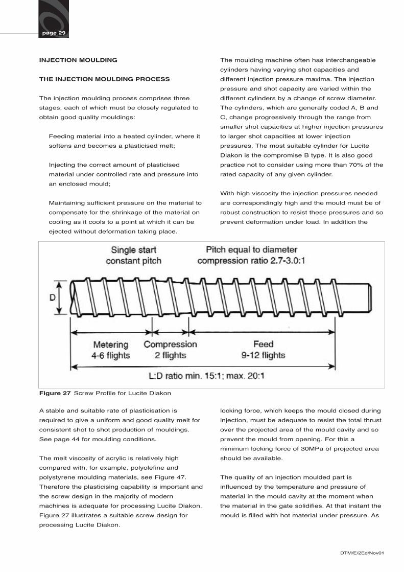
Figure 27 Screw Profile for Lucite Diakon
A stable and suitable rate of plasticisation is
required to give a uniform and good quality melt for
consistent shot to shot production of mouldings.
See page 44 for moulding conditions.
The melt viscosity of acrylic is relatively high
compared with, for example, polyolefine and
polystyrene moulding materials, see Figure 47.
Therefore the plasticising capability is important and
the screw design in the majority of modern
machines is adequate for processing Lucite Diakon.
Figure 27 illustrates a suitable screw design for
processing Lucite Diakon.
The moulding machine often has interchangeable
cylinders having varying shot capacities and
different injection pressure maxima. The injection
pressure and shot capacity are varied within the
different cylinders by a change of screw diameter.
The cylinders, which are generally coded A, B and
C, change progressively through the range from
smaller shot capacities at higher injection pressures
to larger shot capacities at lower injection
pressures. The most suitable cylinder for Lucite
Diakon is the compromise B type. It is also good
practice not to consider using more than 70% of the
rated capacity of any given cylinder.
With high viscosity the injection pressures needed
are correspondingly high and the mould must be of
robust construction to resist these pressures and so
prevent deformation under load. In addition the
locking force, which keeps the mould closed during
injection, must be adequate to resist the total thrust
over the projected area of the mould cavity and so
prevent the mould from opening. For this a
minimum locking force of 30MPa of projected area
should be available.
The quality of an injection moulded part is
influenced by the temperature and pressure of
material in the mould cavity at the moment when
the material in the gate solidifies. At that instant the
mould is filled with hot material under pressure. As
DTM/E/2Ed/Nov01
page 30
the temperature of the material in the mould falls
there are two opposing actions taking place:
Thermal contraction - tending to reduce the
volume of the moulding;
Residual pressure in the melt - tending to
expand the moulding slightly.
The two effects occur at the same time and tend
to counterbalance each other.
The use of programmed injection enables moulds to
be filled at different speeds and pressure during the
injection period. The advantage of being able to fill
the major proportion of a mould quickly whilst at
high pressure and speed and then drop to lower
values maintaining follow-up pressure on the
material helps to reduce the risk of flash and the
degree of moulded-in strain. When using this system
for thick acrylic sections, such as lenses and insignia,
it is possible to inject very slowly at a low pressure
and then, towards the end of the mould filling time, to
increase the pressure to help overcome the
shrinkage.
Control of mould temperature is also important if the
quality of the moulded part is to be kept consistent
throughout production. The use of mould
temperature control units allows the mould
temperature to be raised to its optimum value
before start-up, thus avoiding an initial period of
production of more highly strained parts from a cold
mould, and wastage of material due to short shots.
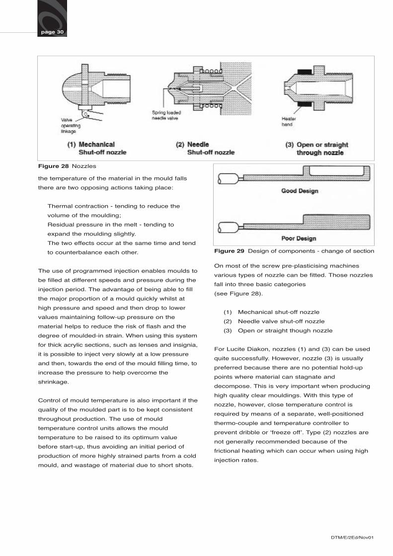
Figure 28 Nozzles
On most of the screw pre-plasticising machines
various types of nozzle can be fitted. Those nozzles
fall into three basic categories
(see Figure 28).
(1) Mechanical shut-off nozzle
(2) Needle valve shut-off nozzle
(3) Open or straight though nozzle
For Lucite Diakon, nozzles (1) and (3) can be used
quite successfully. However, nozzle (3) is usually
preferred because there are no potential hold-up
points where material can stagnate and
decompose. This is very important when producing
high quality clear mouldings. With this type of
nozzle, however, close temperature control is
required by means of a separate, well-positioned
thermo-couple and temperature controller to
prevent dribble or ‘freeze off’. Type (2) nozzles are
not generally recommended because of the
frictional heating which can occur when using high
injection rates.
Figure 29 Design of components - change of section
DTM/E/2Ed/Nov01
page 31
DESIGN OF COMPONENTS FOR MOULDING
Good component design is of great importance in
the injection moulding of Lucite Diakon and the
following points should be considered at the design
stage if later difficulties are to be minimised or
avoided.
If possible, sharp change of section thickness should
be avoided as this creates excessive moulding flow
problems with thicker sections and the possibility of
excessive sinking on cooling if the gating position is
only permissible at the thinner part of the moulding.
To keep the cross-section constant, thick sections
should be cored out wherever possible (Figure 29).
With certain designs, as for example the prismatic
effect in a tap handle, thick and thin sections are
closely alternated. In this instance the rapid change
in section gives attractive optical results, but
differential thicknesses must be kept within certain
limits to avoid problems in moulding or in service.
As a guide, the thickest sections should not exceed
10 mm. Even then, as the mould cavity fills, the melt
will tend to flow into the thick sections first and the
thin ones thereafter, leaving a weld line where the
adjacent flows of melt re-unite. All edges of the core
pin (which forms the hollow in the handle) should be
radiused to ensure that the melt will not drag over
them with consequent formation of flow lines, and to
reduce the possibility of stress cracking by
eliminating sharp corners in the moulding. Different
cooling rates of thick and thin sections can also lead
to stresses in the finished moulding.
To achieve economy, components are often reduced
in section. This practice can be followed provided
the sections are not made so thin as to cause flow
problems during moulding. In addition to the flow
problems, thin sections cool rapidly in the mould and
result in high quenching stresses which make
mouldings more liable to craze and crack. As a
guide, where long flow paths are encountered, wall
sections should not be less than 3 mm.
Problems resulting from uneven filling of the mould
cavity will occur if the component is surrounded by a
rim which is thicker than the internal portion in the
centre (Figure 30). In this instance material will flow
around the rim faster than across the centre and then
give gas entrapment and “Y” weld line problems.
Figure 30 Design of components - thickness of rim
All corners and sections should be radiused as sharp
corners cause stress concentration, brittle moulding
and also pressure drop leading to possible problems in
mould filling. This particularly applies where blind
holes are to be moulded-in to take screw or other
fastening media. Wherever possible all holes and slots
should be moulded-in since post-moulding machining
operations not only increase finished part cost, but
also set up residual stresses which can only be
removed by annealing.
To maintain the benefits arising from increased impact
strength and flexibility with Lucite Diakon ST grades, it
is important, at the initial design stage of components,
to avoid sharp corners and sudden changes in section
thickness, thereby eliminating areas subject to high
tensile stress as with standard grades. All such corners
should have a minimum radius of 1.5-2.0 mm. It is also
important in the design and gating of the components
to pay attention to the avoidance of weld lines as this
effect, common to many impact modified plastics, is
more noticeable than with a similar component in a
standard Lucite Diakon grade.
If inserts are to be moulded-in, sufficient material
should be allowed around the insert to give adequate
keying and to resist stresses which will be set up
during cooling by the differential thermal contraction of
the insert and the Lucite Diakon. High softening point
plastic inserts like glass reinforced nylon are preferable
to metal to minimise the stress. The insert should be
splined on the outside and provided with a
circumferential slot to give a key to the Lucite Diakon
which is moulded over it.
DTM/E/2Ed/Nov01
page 32
When numerals or letters are to be moulded into the
component these should not be more than one third of
the depth of the section thickness in order to minimise
division of the melt leading to weld lines and ‘tails’.
To aid ejection, the draft angle on a component should
be as generous as possible. This especially applies to
thick components where long injection times are often
necessary and consequently increases moulding
packing. In general 1° suffices for most thinner sections
but as much as 3-4° may have to be accepted in
extreme circumstances.
The shape of the component often dictates the
positions of the mould parting line, gate and ejection
points, and these should be taken into account at the
design stage in order to facilitate the moulding of
good quality components without objectionable
appearance defects.
With tap handles or control knobs the use of a splined
spigot is recommended.
With splined spigots the torque is distributed very
evenly and a matching hole may therefore be moulded
into the boss of the tap handle. The crests and valleys
of the splining should be radiused to reduce and
distribute any stresses which might be generated by
excessive pressure.
With a square section spigot, the torque applied is
concentrated at the internal angles of the moulded
square hole, and cracking could occur.
MULTI-COLOURED MOULDINGS
The techniques described below have been highly
successful with Lucite Diakon, particularly in the
automotive industry on rear light assemblies.
Edge-to-Edge Insert Moulding
The process involves moulding part of a complete
assembly in one tool, and transferring this part to a
second tool, where further material is moulded
against this insert. The hot melt fuses with the
inserted moulding producing a bond between the
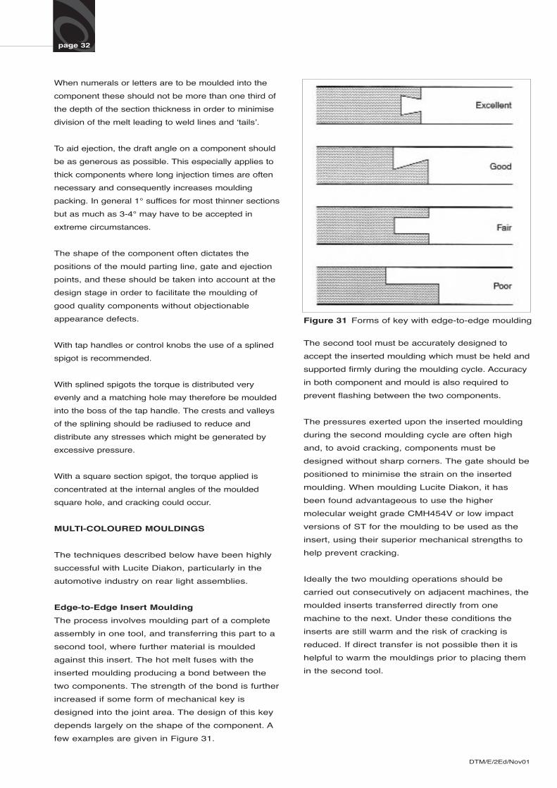
two components. The strength of the bond is further
increased if some form of mechanical key is
designed into the joint area. The design of this key
depends largely on the shape of the component. A
few examples are given in Figure 31.
Figure 31 Forms of key with edge-to-edge moulding
The second tool must be accurately designed to
accept the inserted moulding which must be held and
supported firmly during the moulding cycle. Accuracy
in both component and mould is also required to
prevent flashing between the two components.
The pressures exerted upon the inserted moulding
during the second moulding cycle are often high
and, to avoid cracking, components must be
designed without sharp corners. The gate should be
positioned to minimise the strain on the inserted
moulding. When moulding Lucite Diakon, it has
been found advantageous to use the higher
molecular weight grade CMH454V or low impact
versions of ST for the moulding to be used as the
insert, using their superior mechanical strengths to
help prevent cracking.
Ideally the two moulding operations should be
carried out consecutively on adjacent machines, the
moulded inserts transferred directly from one
machine to the next. Under these conditions the
inserts are still warm and the risk of cracking is
reduced. If direct transfer is not possible then it is
helpful to warm the mouldings prior to placing them
in the second tool.
DTM/E/2Ed/Nov01
page 33
Skin Insert Moulding
This process is similar to that described above
except that the insert is a thin component with
smooth surfaces, normally in the region of 1.5 mm
thick. Many of the points mentioned above apply to
skin moulding. The final part is produced by
moulding a second layer skin, which will include the
optics, on to the first in a master tool. It has been
found that when required the use of CMH454V for
the insert skin helps to minimise cracking or colour
bleeding problems. Although, due to component
and tooling considerations, both edge-to-edge and
skin moulding techniques are used, it is considered
skin moulded lenses are more robust than edge to
edge ones.
Multi-Colour Machines
Multi-colour moulding may also be carried out on
special machines with two or more cylinders for
those rearlight assemblies where design, size and
number considerations are suitable. The technique
usually consists of a series of moulds where one
platen is rotated through two or more stations
where injection of the different coloured material
takes place.
MOULD DESIGN
Although many factors have to be considered in the
design of moulds for thermoplastic materials there
are three factors which require special attention for
acrylic materials. Due to the relatively high melt
viscosity and its greater temperature dependence
(see Figure 47) it is usually necessary to use
sprues, runners and gates of generous cross
section compared to those used for material with
low viscosities such as nylon and polystyrene.
Standard grades of Lucite Diakon may be considered
as hard brittle materials and allowance should be
made for this.
• Radius all corners
• Adequate and uniform ejection
• No undercuts
• Minimum 1° taper
• Polish in line of draw
• Uniform mould temperature control
The aesthetic appearance together with high gloss
and clarity obtainable with Lucite Diakon mouldings
requires highly polished moulds.
In general nickel-chrome steels are preferred since in
addition to being tough and hard-wearing they will
take a high polish. For optical quality parts, a steel
like ‘Stavex’* ESR has been found satisfactory.
Sprue Design
The sprue is the channel through which the material
is transferred from the machine nozzle to the
runner(s) and gate(s) and into the mould cavity (ies).
Its design, therefore, is of paramount importance. It
must be of adequate dimensions to prevent freezing
prematurely, but not so large as to extend the cooling
time of the moulding. To fulfil these basic
requirements it is thus important to have a sprue of
adequate diameter but to keep it as short as possible.
A length of approximately 60 mm should be aimed for.
To achieve this mould backing plates or bolsters
should be kept as thin as possible without sacrificing
strength in the mould.
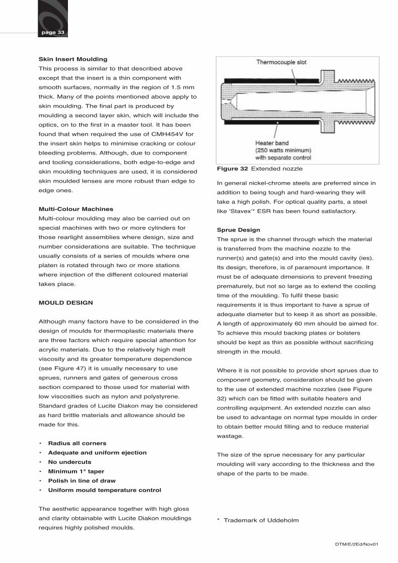
Where it is not possible to provide short sprues due to
component geometry, consideration should be given
to the use of extended machine nozzles (see Figure
32) which can be fitted with suitable heaters and
controlling equipment. An extended nozzle can also
be used to advantage on normal type moulds in order
to obtain better mould filling and to reduce material
wastage.
The size of the sprue necessary for any particular
moulding will vary according to the thickness and the
shape of the parts to be made.
* Trademark of Uddeholm
Figure 32 Extended nozzle
DTM/E/2Ed/Nov01
page 34
As a guide the following sprue diameters should be
used:
For thin section moulding, ie 2.5 mm-4 mm, the
machine nozzle should be 4 mm diameter and the
smaller hole in the sprue bush 4.5 mm diameter;
For thick section mouldings, ie 6 mm and upwards,
the machine nozzle should be 7.5 mm diameter
and the sprue accordingly 8.5 mm diameter.
All sprue bushes should have a tapered bore to allow
easy extraction of the sprue. The angle of the taper
should be between 5-7° inclusive. The higher angle is
preferred for thick mouldings because the long
injection times necessary for these mouldings can
cause packing which tends to make the sprue more
difficult to extract. The sprue bush internal surface
should be free from machine and grinding marks and
should preferably be draw-polished. A generous ‘cold
slug-well’ should be positioned opposite the entrance
of the sprue into the mould whenever possible. In
addition to removing the piece of slightly chilled
material left in the nozzle from the previous shot, it
may also be designed with a ‘Z pin or back taper to
aid the removal of the sprue from the sprue-bush.
The cold ‘slug-well’ is ejected with the moulding and
runner system.
Runner Design
To facilitate the production of good quality mouldings,
particular attention should be paid to the design and
layout of the runner system.
Runners, like sprues, should be generous in diameter
and short in length to minimise pressure loss and
permit adequate follow-up pressure in the initial stage
of cooling.
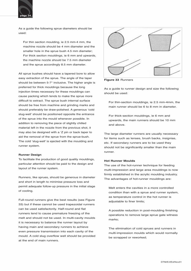
Full-round runners give the best results (see Figure
33) but if these cannot be used trapezoidal runners
can be used satisfactorily. Half-round and flat
runners tend to cause premature freezing of the
melt and should not be used. In multi-cavity moulds
it is necessary to balance the runner layout by
having main and secondary runners to achieve
even pressure transmission into each cavity of the
mould. A cold slug overflow well should be provided
at the end of main runners.
Figure 33 Runners
As a guide to runner design and size the following
should be used:
For thin-section mouldings, ie 2.5 mm-4mm, the
main runner should be 6 to 8 mm in diameter.
For thick-section mouldings, ie 6 mm and
upwards, the main runners should be 10 mm
and above.
The large diameter runners are usually necessary
for items such as lenses, brush backs, insignias,
etc. If secondary runners are to be used they
should not be significantly smaller than the main
runner.
Hot Runner Moulds
The use of the hot-runner technique for feeding
multi-impression and large area mouldings is now
firmly established in the acrylic moulding industry.
The advantages of hot-runner mouldings are:
Melt enters the cavities in a more controlled
condition than with a sprue and runner system,
as temperature control in the hot runner is
adjustable to finer limits;
A possible reduction in post-moulding finishing
operations to remove large sprue gate witness
marks;
The elimination of cold sprues and runners in
multi-impression moulds which would normally
be scrapped or reworked;
DTM/E/2Ed/Nov01
page 35
Hot-runners enable single impression, large area
mouldings to be edge-gated, whilst keeping the
moulding in the centre of the machine platen.
Effective increase in the shot capacity of the
machine as, once the hot-runner is filled, the
injection capacity can be fully concentrated into
the cavities.
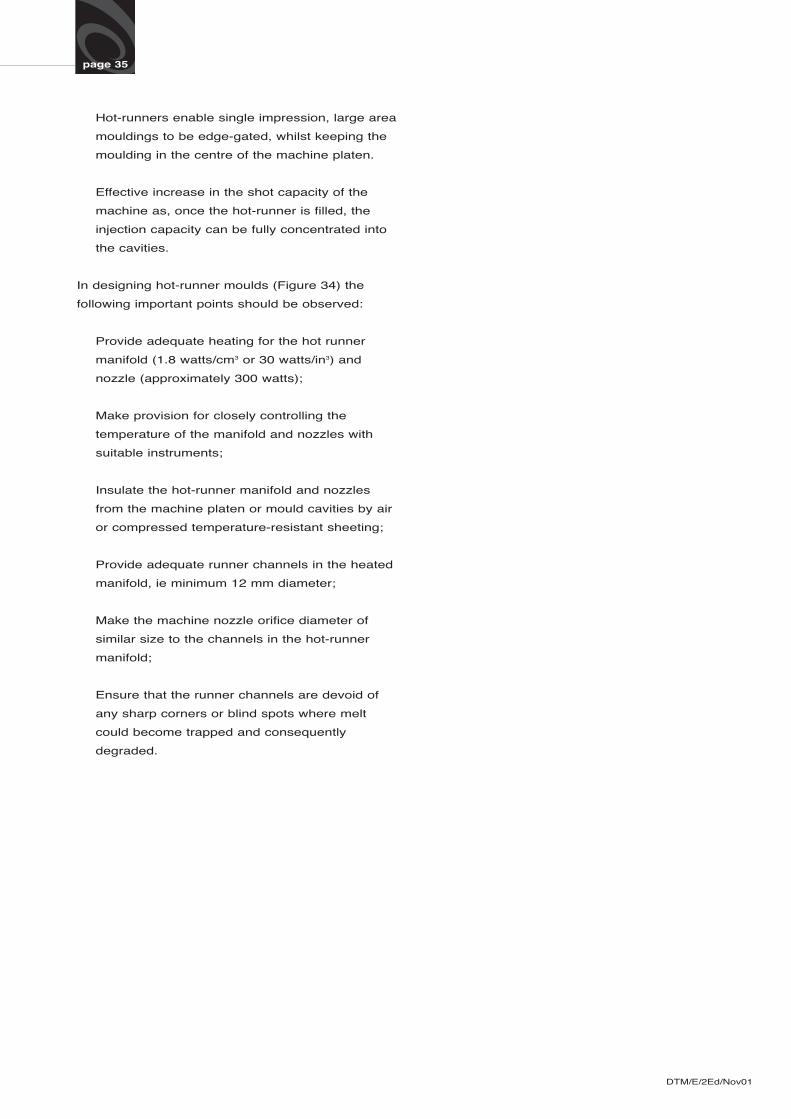
In designing hot-runner moulds (Figure 34) the
following important points should be observed:
Provide adequate heating for the hot runner
manifold (1.8 watts/cm3 or 30 watts/in3) and
nozzle (approximately 300 watts);
Make provision for closely controlling the
temperature of the manifold and nozzles with
suitable instruments;
Insulate the hot-runner manifold and nozzles
from the machine platen or mould cavities by air
or compressed temperature-resistant sheeting;
Provide adequate runner channels in the heated
manifold, ie minimum 12 mm diameter;
Make the machine nozzle orifice diameter of
similar size to the channels in the hot-runner
manifold;
Ensure that the runner channels are devoid of
any sharp corners or blind spots where melt
could become trapped and consequently
degraded.
DTM/E/2Ed/Nov01
page 36
Figure 34 General Assembly of Hot Runner Mould
DTM/E/2Ed/Nov01
page 37
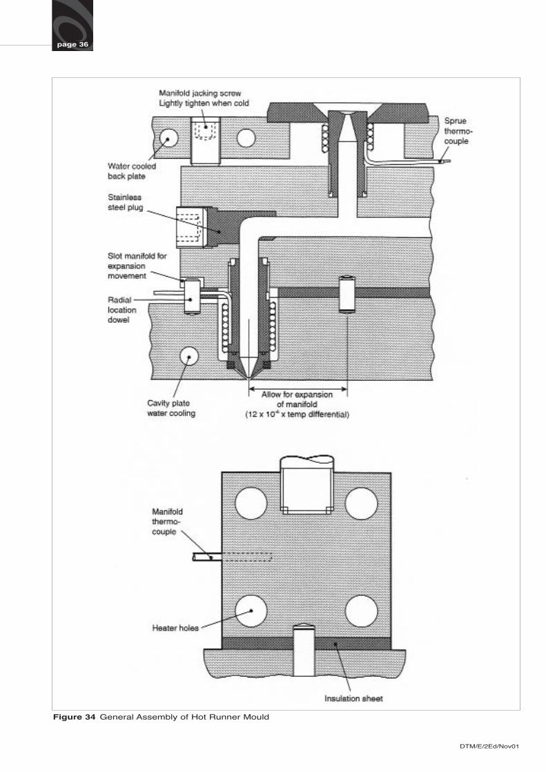
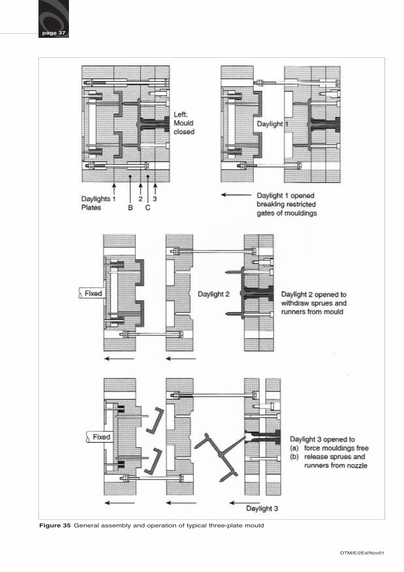
Figure 35 General assembly and operation of typical three-plate mould
page 38
Three-Plate Moulds
These are normally used when multi-cavities for small
components are involved and semi- or fully-automatic
working is required. However, as indicated earlier, due
to the brittle nature of acrylic materials, this type of
design has to be used with care.
This type of mould, as it name suggests, has an extra
plate (see Figure 35). This plate (B) usually carries on
one side the gate and the complete runner system,
preferably trapezoidal, and on the opposite side the
plate carries part of the mould form (usually the
female part).
When the mould opens plate (B) is separated by
means of a delayed action mechanism (eg chains or
length bolts), so breaking the restricted gate. The
mouldings are then ejected from one daylight and the
sprue and runner system are ejected from the other.
Successful ejection of mouldings relies on clean
separation of the moulding and gate at the parting line.
With this method of tooling, restricted gates of the
correct design must be used (see Restricted gate,
Figure 37).
Multi-plate moulds are usually more expensive than
two-plate moulds and can be slower in production if
an operator has to remove the sprue and runner
system when the mould is open. This can usually be
avoided by providing automatic ejection of sprue and
runner. Such a mould is shown in Figure 35 where in
addition to plate (B) the runner is stripped out
automatically with a runner stripper plate (C). The
distance travelled by the plates is governed by the
length of the chain or the length of the bolts used to
separate them.
Gate Design
The type and position of the gate is often dictated by
the design of the component and the number of
mouldings to be produced in each cycle. For guidance
the following section provides information on different
gating methods.
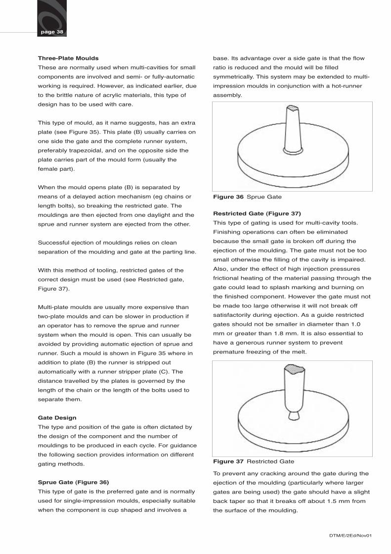
Sprue Gate (Figure 36)
This type of gate is the preferred gate and is normally
used for single-impression moulds, especially suitable
when the component is cup shaped and involves a
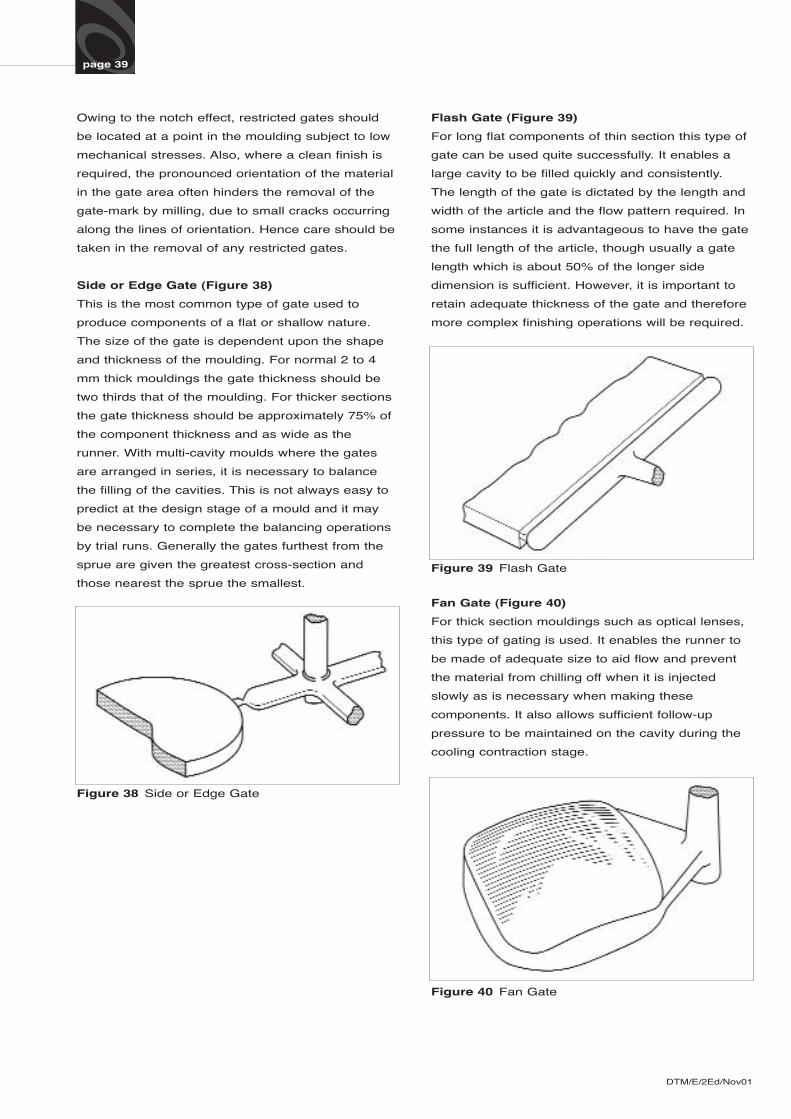
Restricted Gate (Figure 37)
This type of gating is used for multi-cavity tools.
Finishing operations can often be eliminated
because the small gate is broken off during the
ejection of the moulding. The gate must not be too
small otherwise the filling of the cavity is impaired.
Also, under the effect of high injection pressures
frictional heating of the material passing through the
gate could lead to splash marking and burning on
the finished component. However the gate must not
be made too large otherwise it will not break off
satisfactorily during ejection. As a guide restricted
gates should not be smaller in diameter than 1.0
mm or greater than 1.8 mm. It is also essential to
have a generous runner system to prevent
premature freezing of the melt.
DTM/E/2Ed/Nov01
Figure 36 Sprue Gate
Figure 37 Restricted Gate
To prevent any cracking around the gate during the
ejection of the moulding (particularly where larger
gates are being used) the gate should have a slight
back taper so that it breaks off about 1.5 mm from
the surface of the moulding.
base. Its advantage over a side gate is that the flow
ratio is reduced and the mould will be filled
symmetrically. This system may be extended to multi-
impression moulds in conjunction with a hot-runner
assembly.
page 39
Owing to the notch effect, restricted gates should
be located at a point in the moulding subject to low
mechanical stresses. Also, where a clean finish is
required, the pronounced orientation of the material
in the gate area often hinders the removal of the
gate-mark by milling, due to small cracks occurring
along the lines of orientation. Hence care should be
taken in the removal of any restricted gates.
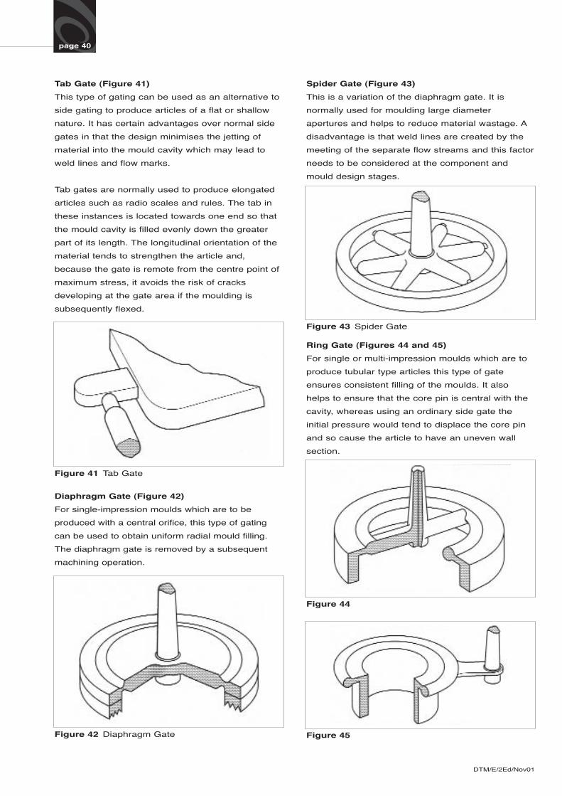
Side or Edge Gate (Figure 38)
This is the most common type of gate used to
produce components of a flat or shallow nature.
The size of the gate is dependent upon the shape
and thickness of the moulding. For normal 2 to 4
mm thick mouldings the gate thickness should be
two thirds that of the moulding. For thicker sections
the gate thickness should be approximately 75% of
the component thickness and as wide as the
runner. With multi-cavity moulds where the gates
are arranged in series, it is necessary to balance
the filling of the cavities. This is not always easy to
predict at the design stage of a mould and it may
be necessary to complete the balancing operations
by trial runs. Generally the gates furthest from the
sprue are given the greatest cross-section and
those nearest the sprue the smallest.
Flash Gate (Figure 39)
For long flat components of thin section this type of
gate can be used quite successfully. It enables a
large cavity to be filled quickly and consistently.
The length of the gate is dictated by the length and
width of the article and the flow pattern required. In
some instances it is advantageous to have the gate
the full length of the article, though usually a gate
length which is about 50% of the longer side
dimension is sufficient. However, it is important to
retain adequate thickness of the gate and therefore
more complex finishing operations will be required.
DTM/E/2Ed/Nov01
Figure 38 Side or Edge Gate
Figure 39 Flash Gate
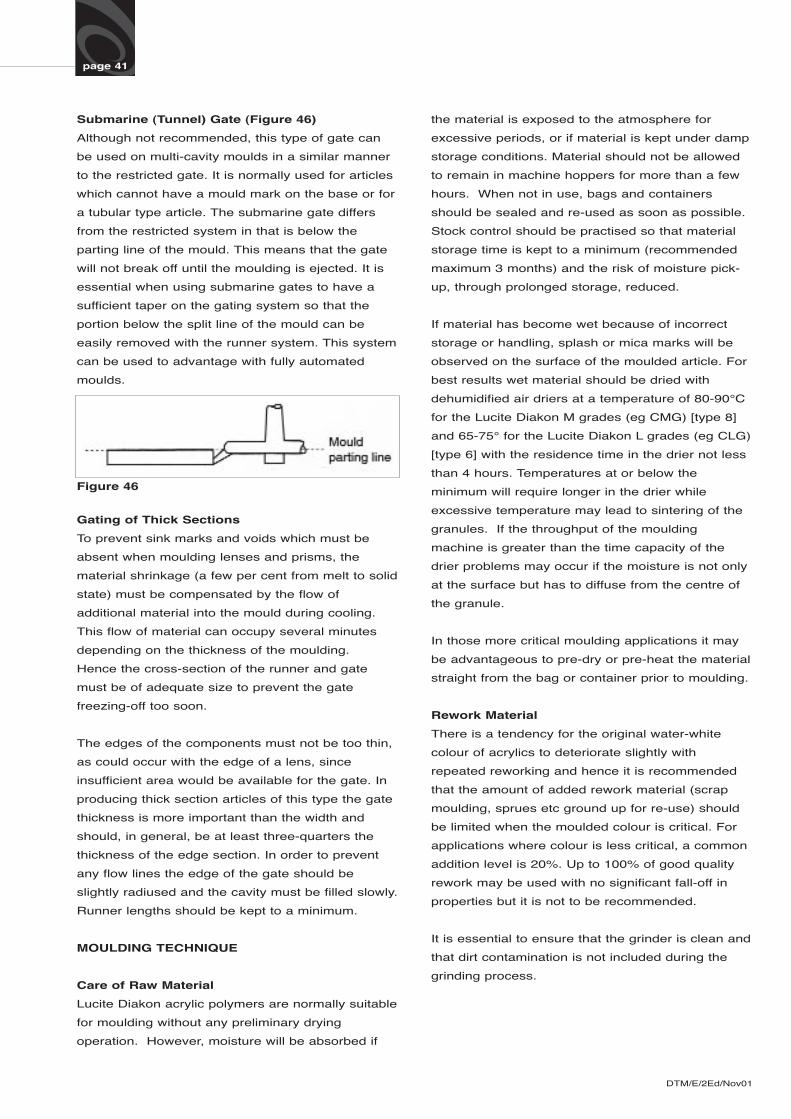
Figure 40 Fan Gate
Fan Gate (Figure 40)
For thick section mouldings such as optical lenses,
this type of gating is used. It enables the runner to
be made of adequate size to aid flow and prevent
the material from chilling off when it is injected
slowly as is necessary when making these
components. It also allows sufficient follow-up
pressure to be maintained on the cavity during the
cooling contraction stage.
DTM/E/2Ed/Nov01
Spider Gate (Figure 43)
This is a variation of the diaphragm gate. It is
normally used for moulding large diameter
apertures and helps to reduce material wastage. A
disadvantage is that weld lines are created by the
meeting of the separate flow streams and this factor
needs to be considered at the component and
mould design stages.
page 40
Tab Gate (Figure 41)
This type of gating can be used as an alternative to
side gating to produce articles of a flat or shallow
nature. It has certain advantages over normal side
gates in that the design minimises the jetting of
material into the mould cavity which may lead to
weld lines and flow marks.
Tab gates are normally used to produce elongated
articles such as radio scales and rules. The tab in
these instances is located towards one end so that
the mould cavity is filled evenly down the greater
part of its length. The longitudinal orientation of the
material tends to strengthen the article and,
because the gate is remote from the centre point of
maximum stress, it avoids the risk of cracks
developing at the gate area if the moulding is
subsequently flexed.
Figure 41 Tab Gate
Figure 44
Figure 45
Figure 43 Spider Gate
Figure 42 Diaphragm Gate
Diaphragm Gate (Figure 42)
For single-impression moulds which are to be
produced with a central orifice, this type of gating
can be used to obtain uniform radial mould filling.
The diaphragm gate is removed by a subsequent
machining operation.
Ring Gate (Figures 44 and 45)
For single or multi-impression moulds which are to
produce tubular type articles this type of gate
ensures consistent filling of the moulds. It also
helps to ensure that the core pin is central with the
cavity, whereas using an ordinary side gate the
initial pressure would tend to displace the core pin
and so cause the article to have an uneven wall
section.
page 41
Submarine (Tunnel) Gate (Figure 46)
Although not recommended, this type of gate can
be used on multi-cavity moulds in a similar manner
to the restricted gate. It is normally used for articles
which cannot have a mould mark on the base or for
a tubular type article. The submarine gate differs
from the restricted system in that is below the
parting line of the mould. This means that the gate
will not break off until the moulding is ejected. It is
essential when using submarine gates to have a
sufficient taper on the gating system so that the
portion below the split line of the mould can be
easily removed with the runner system. This system
can be used to advantage with fully automated
moulds.
the material is exposed to the atmosphere for
excessive periods, or if material is kept under damp
storage conditions. Material should not be allowed
to remain in machine hoppers for more than a few
hours. When not in use, bags and containers
should be sealed and re-used as soon as possible.
Stock control should be practised so that material
storage time is kept to a minimum (recommended
maximum 3 months) and the risk of moisture pick-
up, through prolonged storage, reduced.
If material has become wet because of incorrect
storage or handling, splash or mica marks will be
observed on the surface of the moulded article. For
best results wet material should be dried with
dehumidified air driers at a temperature of 80-90°C
for the Lucite Diakon M grades (eg CMG) [type 8]
and 65-75° for the Lucite Diakon L grades (eg CLG)
[type 6] with the residence time in the drier not less
than 4 hours. Temperatures at or below the
minimum will require longer in the drier while
excessive temperature may lead to sintering of the
granules. If the throughput of the moulding
machine is greater than the time capacity of the
drier problems may occur if the moisture is not only
at the surface but has to diffuse from the centre of
the granule.
In those more critical moulding applications it may
be advantageous to pre-dry or pre-heat the material
straight from the bag or container prior to moulding.
Rework Material
There is a tendency for the original water-white
colour of acrylics to deteriorate slightly with
repeated reworking and hence it is recommended
that the amount of added rework material (scrap
moulding, sprues etc ground up for re-use) should
be limited when the moulded colour is critical. For
applications where colour is less critical, a common
addition level is 20%. Up to 100% of good quality
rework may be used with no significant fall-off in
properties but it is not to be recommended.
It is essential to ensure that the grinder is clean and
that dirt contamination is not included during the
grinding process.
DTM/E/2Ed/Nov01
Figure 46
Gating of Thick Sections
To prevent sink marks and voids which must be
absent when moulding lenses and prisms, the
material shrinkage (a few per cent from melt to solid
state) must be compensated by the flow of
additional material into the mould during cooling.
This flow of material can occupy several minutes
depending on the thickness of the moulding.
Hence the cross-section of the runner and gate
must be of adequate size to prevent the gate
freezing-off too soon.
The edges of the components must not be too thin,
as could occur with the edge of a lens, since
insufficient area would be available for the gate. In
producing thick section articles of this type the gate
thickness is more important than the width and
should, in general, be at least three-quarters the
thickness of the edge section. In order to prevent
any flow lines the edge of the gate should be
slightly radiused and the cavity must be filled slowly.
Runner lengths should be kept to a minimum.
MOULDING TECHNIQUE
Care of Raw Material
Lucite Diakon acrylic polymers are normally suitable
for moulding without any preliminary drying
operation. However, moisture will be absorbed if
page 42
The screen size on the grinder should be 3 mm- 6
mm. Larger screens should not be used since
difficulty could be encountered in feeding, melting
and processing larger particles, particularly if rework
material is being blended with coloured material or
used on shallow-flighted screws.
It is usually necessary to dry rework material prior
to moulding if it has been exposed to the
atmosphere for any length of time. The drying
conditions for rework material are the same as used
for virgin material. It is generally possible, by
grinding sprues and runners soon after they have
been moulded and keeping the material protected
from the atmosphere, to mould it without drying.
Contamination
Lucite Diakon is not compatible with other moulding
materials and strict precautions must be taken to
prevent contamination which is immediately visible
because of the high transparency of the material.
Contamination with other clear materials
(polystyrene and polycarbonate) results in white
cloudy streaks due to differences in refractive index.
Because Lucite Diakon is a good electrical
insulator, it will pick up atmospheric dust by
electrostatic attraction. Care must therefor be taken
when loading machine hoppers to prevent
unnecessary exposure.
Purging
Being a clear material, the changeover from other
materials to Lucite Diakon is more difficult than with
opaque plastics, and many moulders keep a
separate cylinder soley for moulding acrylic. Where
a separate cylinder for acrylic is not available the
most convenient way to clean the cylinder, apart
from a complete strip down, is to purge the machine
using rework Lucite Diakon with the nozzle
removed. The nozzle can be ‘burnt out’ separately.
Where black or heavily filled materials are to be
removed from the cylinder it is useful to use scrap
natural unfilled polypropylene as a purging
compound before changing over to rework Lucite
Diakon.
When purging it is recommended that the cylinder
temperatures be raised during the initial stages of
the operation. This assists removal of material from
cylinder walls. Obviously care must be taken not to
disrupt the carbonised layer on the screw and barrel
or use excessive temperatures which could cause
severe decomposition of the material. After a short
while, temperatures should be reduced and the
machine purged with Lucite Diakon at lower
temperatures to remove remaining traces of
unwanted material. Once the purging operation is
complete a clean nozzle should be fitted.
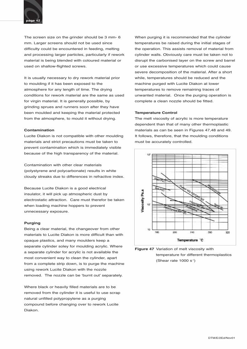
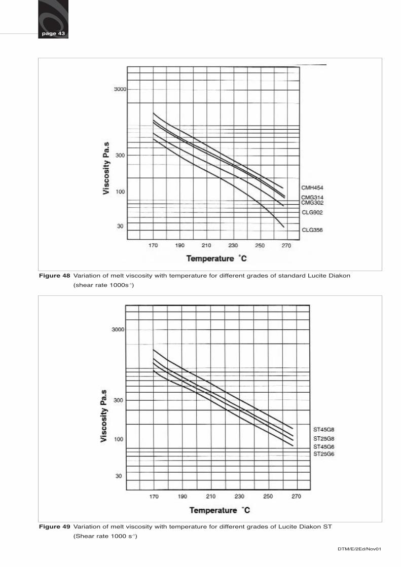
Temperature Control
The melt viscosity of acrylic is more temperature
dependent than that of many other thermoplastic
materials as can be seen in Figures 47,48 and 49.
It follows, therefore, that the moulding conditions
must be accurately controlled.
DTM/E/2Ed/Nov01
Figure 47 Variation of melt viscosity with
temperature for different thermoplastics
(Shear rate 1000 s-1)
DTM/E/2Ed/Nov01
page 43
Figure 48 Variation of melt viscosity with temperature for different grades of standard Lucite Diakon
(shear rate 1000s-1)
Figure 49 Variation of melt viscosity with temperature for different grades of Lucite Diakon ST
(Shear rate 1000 s-1)
DTM/E/2Ed/Nov01
page 44
Position of Thermocouples
Controlling thermocouples should be located as
close as possible to the heaters they control, eg in
a slot directly under the band heaters. This
arrangement eliminates any time lag in the
response of the controllers and minimises cyclic
variations in temperature.
Measurement of cylinder wall temperatures may be
made by a set of deeply recessed thermocouples
connected to a separate recorder. Such facility is not
essential for production purposes but it is a useful
guide for establishing optimum conditions and for
experimental work.
Nozzle Temperature Control
This subject is discussed on page 30 but it is
recommended that wherever possible separate
control of the nozzle temperature should be used.
For long or extended nozzles separate control is
essential to minimise any defects such as matt
patches or splash marking around the sprue which
occur because of the nozzle being too cold or
too hot.
Moulding Conditions
The actual moulding temperatures and pressure
setting required will vary from grade to grade and
from one type of machine to another, depending on
the size of the machine and the shot weight of the
moulding. They will also depend on the design and
section thickness of the component. The material
temperature may be higher or lower than the
indicated cylinder temperature depending on the
amount of frictional heat introduced by the screw. It
is therefore not possible to be specific about the
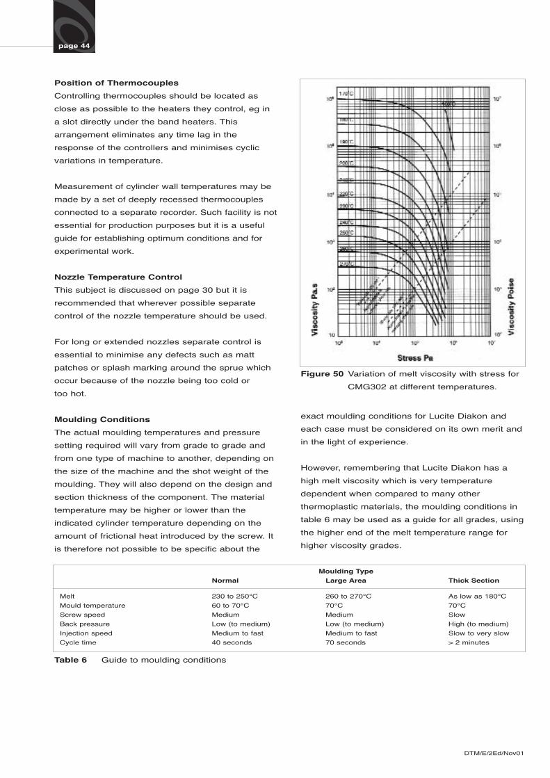
Figure 50 Variation of melt viscosity with stress for
CMG302 at different temperatures.
exact moulding conditions for Lucite Diakon and
each case must be considered on its own merit and
in the light of experience.
However, remembering that Lucite Diakon has a
high melt viscosity which is very temperature
dependent when compared to many other
thermoplastic materials, the moulding conditions in
table 6 may be used as a guide for all grades, using
the higher end of the melt temperature range for
higher viscosity grades.
Moulding Type
Normal Large Area Thick Section
Melt 230 to 250°C 260 to 270°C As low as 180°C
Mould temperature 60 to 70°C 70°C 70°C
Screw speed Medium Medium Slow
Back pressure Low (to medium) Low (to medium) High (to medium)
Injection speed Medium to fast Medium to fast Slow to very slow
Cycle time 40 seconds 70 seconds > 2 minutes
Table 6 Guide to moulding conditions
DTM/E/2Ed/Nov01
page 45
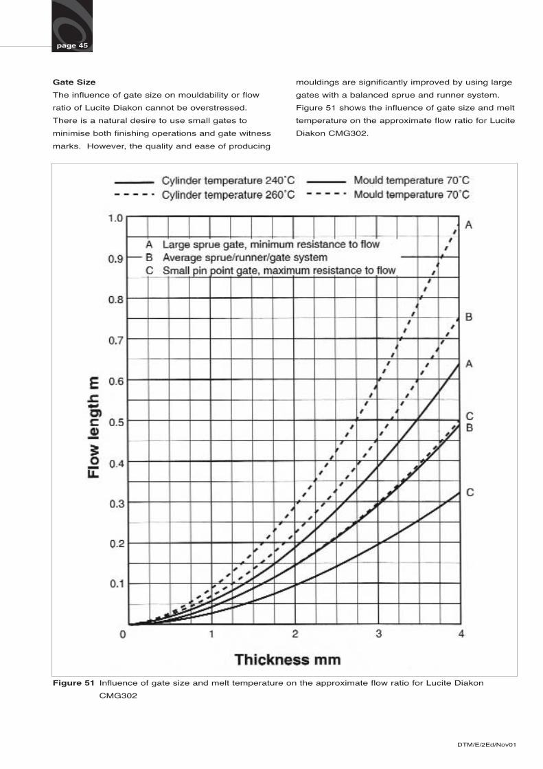
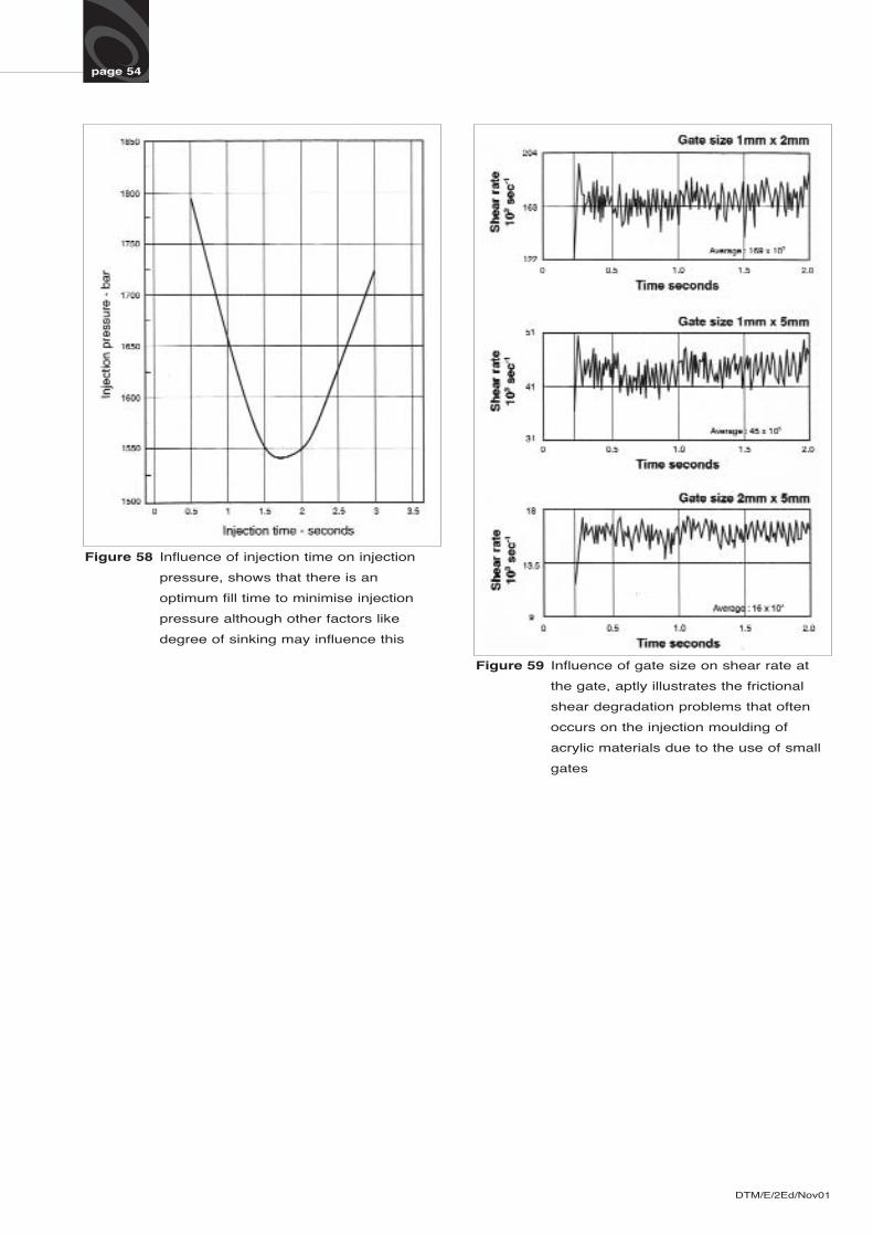
Gate Size
The influence of gate size on mouldability or flow
ratio of Lucite Diakon cannot be overstressed.
There is a natural desire to use small gates to
minimise both finishing operations and gate witness
marks. However, the quality and ease of producing
Figure 51 Influence of gate size and melt temperature on the approximate flow ratio for Lucite Diakon
CMG302
mouldings are significantly improved by using large
gates with a balanced sprue and runner system.
Figure 51 shows the influence of gate size and melt
temperature on the approximate flow ratio for Lucite
Diakon CMG302.
page 46
Cylinder Temperatures
Due to the many factors influencing material or melt
temperature it should be noted that melt and cylinder
temperatures are unlikely to be identical and in fact
may differ by a significant amount.
The approximate range of melt temperature over which
Lucite Diakon may be moulded is 200 to 270°C. For
average size mouldings the easy flow Lucite Diakon
type 6 grades will be in the low to middle range and the
higher viscosity Lucite Diakon Type 8 grades in the
middle to high range. It is common to optimise
temperature settings by applying a small gradient to the
cylinder temperature; 5 to 10°C lower at the nozzle and
10 to 20°C lower at the rear or feed zone.
In the absence of experience or correlation between
melt and cylinder temperatures then initial cylinder
temperature settings of 240°C are recommended.
Mould Temperature
It is essential when moulding Lucite Diakon to have
adequate provision for controlling the mould
temperature. Both halves of the mould should be cored
for circulating water at a controlled temperature. With
some mould designs and component shapes it may
well be necessary to control the mould halves at
different temperatures to achieve an acceptable
product. A separate circuit should be used to control
the sprue bush temperature.
The recommended mould temperature for the Lucite
Diakon type 8 grades is between 60 and 80°C
depending upon section thickness and flow path, and
for Lucite Diakon type 6 grades 55-70°C.
Machine Start-Up
Injection moulding machines should not be allowed to
stand idle for long times while at moulding
temperatures, since this allows heat to conduct
backwards along the screw and could cause material to
melt on to the feed section of the screw and create an
obstruction. Where a delay is involved, rear temperature
should be temporarily reduced. Controlled water should
be circulated around the feed pocket during the heating
up period to prevent this section from becoming too hot
and causing sticking of prematurely melted material.
When in production the feed throat should be
maintained between 40 and 60°C.
If any mould setting is required on the injection unit this
should be done once the cylinder has attained the
moulding temperature. The machine and mould should
never be ‘set’ when cold, otherwise the expansion of
the injection unit when it reaches moulding
temperatures could cause serious damage.
Before commencing to mould, the machine should be
purged briefly to ensure that the material in the barrel is
clean and at the right temperature.
Screw Back Pressure
When the screw unit is plasticising, a regulated forward
hydraulic pressure is applied to the screw in partial
opposition to the back pressure generated by the
plasticised melt. The regulated pressure is known as
the screw back pressure or screw reaction pressure. If
this back pressure is greater than the pressure
generated by the melt in front of the screw then no
screw retraction will take place. However, by
adjustment of the screw back pressure, the screw may
be made to refill under controlled conditions and
produce a uniform melt.
Some back pressure is desirable to help expel air from
between the polymer particles or granules and so
prevent air from being included in the melt. Otherwise
this may lead to burning of the material in the cylinder
and may show as splash marks or bubbles (generally
with white inclusions) in the moulding, or in the extreme
case as black streaks. Screw back pressure is also
useful with blends or dry coloured material to aid
mixing, particularly where lightly tinted materials are
being processed. An increase in screw back pressure
causes more work to be done on the material and so
enhances mixing. However, excessive use of back
pressure can lead to overheating of the material die to
frictional heat, which will show as splash marks and
could eventually lead to screw slip (see below) due to
overheating of material on the rear section of the screw.
Screw Speed
Because acrylic moulding materials have relatively high
melt viscosities, attention must be paid to the screw
speed to avoid excessive frictional heating and
degradation. The screw speeds to be used vary
according to the size of machine (ie screw diameter)
and type of article being moulded, but in general they
should be kept as low as possible consistent with an
acceptable cycle time. For shot weights up to 250g
screw speeds of 80-100 rpm are used satisfactorily; for
machines with large diameter screws it is necessary to
keep screw speeds low in the range of 30-40 rpm.
DTM/E/2Ed/Nov01
page 47
Where temperature controllers indicate a marked
tendency to override the preferred set temperature
due to frictional heating, then adjustment of screw
speed and back pressure should be considered. If
full correction by this means is not possible, but the
developed temperature can be accepted, then the
temperature controller should be re-set to control
the temperature at a higher level.
Screw Slip
This term is applied when the screw turns but does
not refill. It is generally caused by molten or semi-
molten material, in or close to the feed section,
sticking to the screw flights and so impeding the
entry of fresh material into the cylinder. It can also
be caused by too high a screw back pressure.
Screw slip can occasionally occur during start-up.
This arises because the machine has been allowed
to stand at moulding temperature for too long a
time. Under these conditions, heat from the cylinder
conducts along the screw raising the temperature of
the rear section of the screw which then causes
premature melting of material in the feed flights.
This is especially so if the screw flights are full of
material.
To overcome screw slip, ie remove the blockage
caused by molten or semi-molten material, the
temperatures of the rear zone and feed pocket
should be lowered, insuring cooling water is
circulating around the feed throat and the machine
purged with rework material. In extreme instances
the rework material may have to be force-fed on to
the screw. Purging should be continued until the
rear temperature stabilises and the screw refills
consistently.
Where an extended delay is likely to occur it is a
wise precaution to increase cooling to the feed
throat and reduce the rear zone cylinder
temperature to about 150°C.
Injection Speed
There are contradicting requirements on the rate of
filling the mould with acrylic materials. Fast injection
speed decreases cycle time, prevents premature
freezing of the melt before the mould is full and
improves the strength of weld lines. However, with
fast injection speed there is a strong possibility of
frictional heat and splash marking, especially with
small gates, flow lines may be more obvious and
there is a higher risk of flashing the mould.
Programmed injection allows a balanced rate of fill
to be achieved. Fast to medium for the majority of
the shot and medium to slow for the balance.
Shrinkage of Mouldings
Shrinkage of mouldings is caused by the reduction
in volume which the material undergoes when it
changes from the molten to the solid state in the
mould and continues to cool to room temperature.
The shrinkage expressed as a fraction, or as a
percentage, is based on the difference between the
dimensions of the cold moulding and of the cold
mould. The extent of shrinkage of Lucite Diakon,
like that of other thermoplastics, is dependent on
the component design, gate design, moulding
conditions and the manner in which the melt flows
to conform to the shape of the tool.
It is almost impossible to predict accurately the
exact amount of shrinkage which will take place on
a given article but approximate shrinkage figures
which may be used as a guide can be obtained by
measurements made on specific test pieces. If
accurate dimensions are required on the finished
components, it is necessary first to carry out trials
under controlled moulding conditions and then to
make final adjustments to the mould dimensions.
When doing this it is essential to measure the
component sometime after moulding to ensure that
full contraction has occurred. The moulding must be
kept dry during this time and it is important to
measure all critical dimensions both in line with, and
across, the flow path of the material, since
shrinkage can vary with the direction of melt flow.
Shrinkage can be adjusted to some extent by the
moulding conditions, but it must be emphasised that
the amount of shrinkage which may be controlled in
this way is limited and is not always sufficient to
compensate entirely for a mould which has been
made grossly under or over size. This sort of
practice may also lead to the danger of excessive
residual stress in a moulding.
On average the shrinkage of Lucite Diakon is in the
order of 0.3 to 0.7%, the higher shrinkage applying
to a thicker moulding.
DTM/E/2Ed/Nov01
DTM/E/2Ed/Nov01
page 48
From experiments with various components, the
following conclusions can be drawn:
Shrinkage is inversely proportional to injection
pressure;
Shrinkage is directly proportional to mould
temperature;
Shrinkage is directly proportional to melt
temperature.
It is worth noting that the flow pattern to the
component will tend to determine which is the main
factor in controlling the shrinkage of the moulding.
For example, the shrinkage of long thin mouldings
exhibiting linear flow paths will be dependent more
on changes in injection pressure and speed than on
other variables, while shrinkage of moulding
exhibiting radial flow paths will be more dependent
on changes in melt and/or mould temperature.
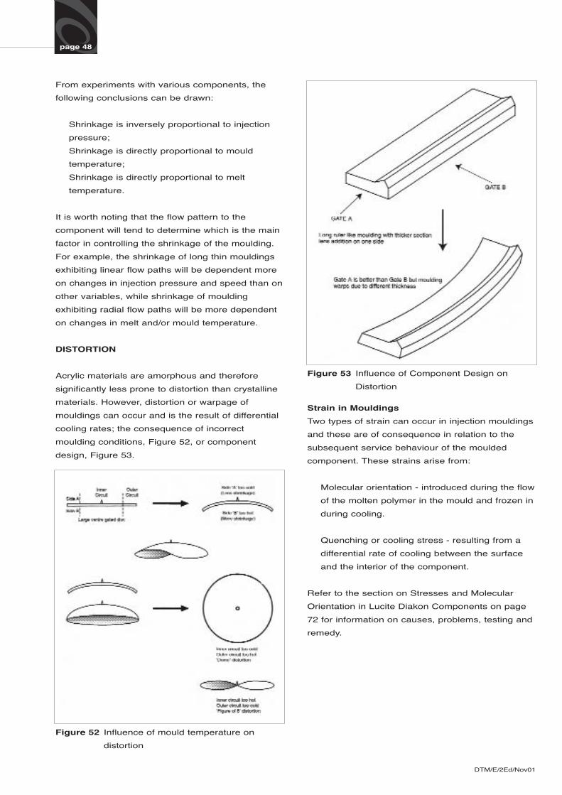
DISTORTION
Acrylic materials are amorphous and therefore
significantly less prone to distortion than crystalline
materials. However, distortion or warpage of
mouldings can occur and is the result of differential
cooling rates; the consequence of incorrect
moulding conditions, Figure 52, or component
design, Figure 53.
Figure 52 Influence of mould temperature on
distortion
Figure 53 Influence of Component Design on
Distortion
Strain in Mouldings
Two types of strain can occur in injection mouldings
and these are of consequence in relation to the
subsequent service behaviour of the moulded
component. These strains arise from:
Molecular orientation - introduced during the flow
of the molten polymer in the mould and frozen in
during cooling.
Quenching or cooling stress - resulting from a
differential rate of cooling between the surface
and the interior of the component.
Refer to the section on Stresses and Molecular
Orientation in Lucite Diakon Components on page
72 for information on causes, problems, testing and
remedy.
page 49
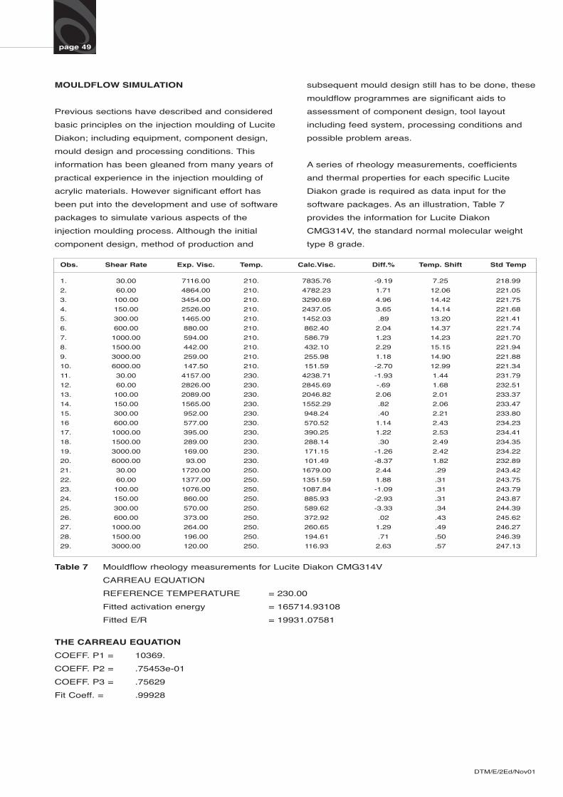
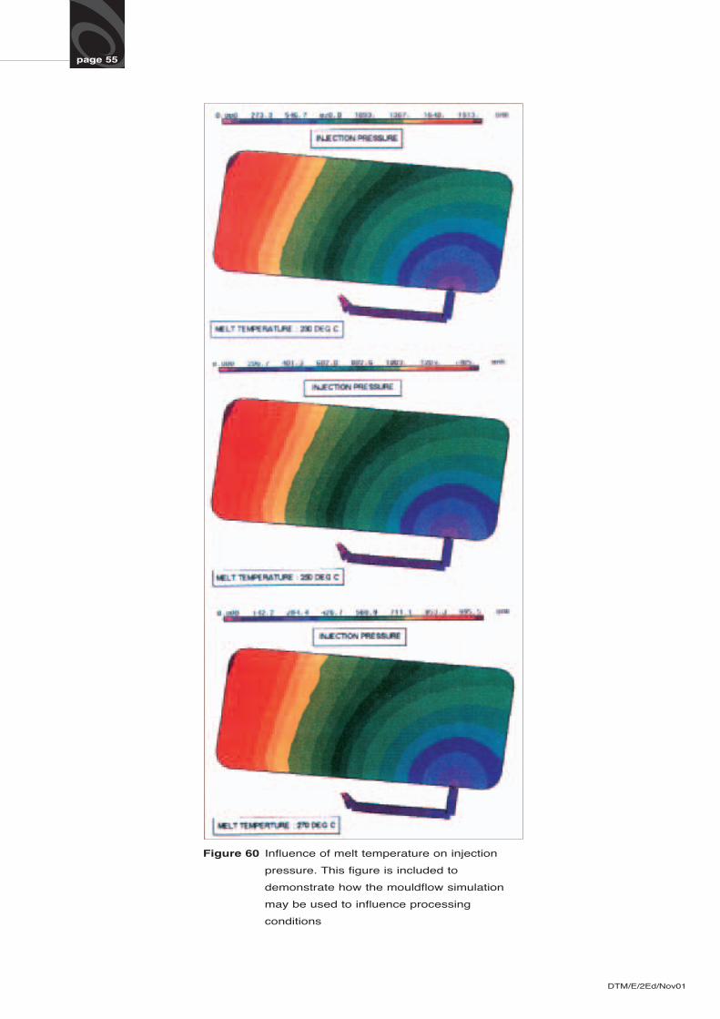
MOULDFLOW SIMULATION
Previous sections have described and considered
basic principles on the injection moulding of Lucite
Diakon; including equipment, component design,
mould design and processing conditions. This
information has been gleaned from many years of
practical experience in the injection moulding of
acrylic materials. However significant effort has
been put into the development and use of software
packages to simulate various aspects of the
injection moulding process. Although the initial
component design, method of production and
subsequent mould design still has to be done, these