14
INLAYS FOR ELECTRONIC INLAYS FOR ELECTRONIC PASSPORT PASSPORT Rolf GRUENHUT Rolf GRUENHUT Warsaw Warsaw , , March March 2006 2006

INLAYS FOR ELECTRONIC INLAYS FOR ELECTRONIC PASSPORTPASSPORTRolf GRUENHUTRolf GRUENHUT
WarsawWarsaw, , MarchMarch 20062006

Agenda
1. RFID Inlay Technology Highlights
2. Inlay for RFID Passport – Cross section
3. Inlay for RFID Passport - Features
4. Inlay for Dual Interface Card – Cross section
5. Comparison of different Antenna Technology
6. Inlay for RFID Passport, Production Layout
7. Inlay for RFID Passport Production Line, Features
8. Inlay for RFID Passport Production Line, Standards

RFID InlayTechnology Highlights
ANTENNA MICROCHIP
CARD BODY
RFID InlayTechnology Highlights
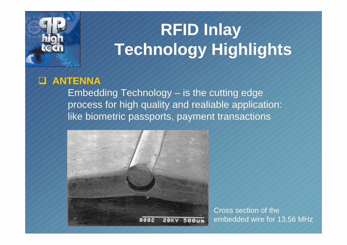
� ANTENNAEmbedding Technology – is the cutting edge process for high quality and realiable application:like biometric passports, payment transactions
Cross section of the embedded wire for 13,56 MHz

RFID InlayTechnology Highlights
� MICROCHIP INTERCONNECTIONTC – Bonding (Thermo Compression Bonding) is themicro welding process. The most reliable method to interconnect insulated cooper wire with a chip module.
Substrate bumping with Au studbumps on Au pads

RFID InlayTechnology Highlights
� CARD BODY - LAMINATION• Key technology in RFID Inlay and Card production.• Unique technology know – how• As a first mover developing the lamination process for high reliable transponder cards production
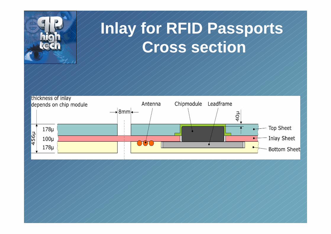
Inlay for RFID PassportsCross section

Inlay for RFID PassportsFeatures
• Format: ID–1, diverse standard sheet available• Construction: cover page, visa pages, holder page• Chip module Philips:
MOB 2 = 390 µmMOB 4 = 320 µm
• Material: PVC, PET, PC• Lifespan: 10 years• ISO Bending Cycle Test: > 50 000 bendings• Operating Temperatures: -20°C - +100°C• Climate Test: 80% humidity/ 1000 hour, 100% hermetically sealed

Inlay for Dual InterfaceCard, ID-CardCross section

Comparison of differentAntenna,
Technology Highlights
etched
Embedded
printed
(conductive inks or
silverfilled epoxies)
Interconnection
Technology
Soldering or
crimping
TC bonding Soldering using
conductive adhesive
Quality of
Interconnection
fair very good poor
Shear tests with Philips
lead frame module
using conductive
adhesive (29-59cN)
>200cN no reliable data
Adhesion of
interconnection when
applying temperature
(especially during hot lamination)
poor
very good
poor
Insulation of antenna
wires (in order to avoid
short circuiting when
crossing tracks)
none
yes
none
Ductility of the conductive tracks
(during bending tests)
good
very good
fair
Elongation factor of
conductive tracks
before fracture
~6%
>20%
2%

Inlay for RFID PassportsProduction Layout
`
Inlay production (sheets) Cover sheet preparation
LaminationTesting

Production Line for RFID Inlays for Passports,
Features• Semiautomatic production line for sheet format
• Easily adapted with additional process units
• Modular platform various process units available
• Minimum conversion time in format change
• Suitable for RFID Passports Inlays, Contactless Cards as well as Dual Interface Cards
• Appropriate for low and high quantities inlay production ,up to 2000 Inlays/hour (one module)

Inlay for RFID PassportsStandards
• Inlay with implemented Smart MX chip P5CD072conform to: ISO 14443 type A, ISO 7816, ICAO 9303, ISO/IEC 7501, CC EAL 5+ (chip), ISO/IEC 15693 (notendorsed for use by ICAO 9303)
• Inlay body tests conform several sections of ISO/IEC 10373 for:- mechanical- visual- chemical- thermal
• Protection against flexing, stamping and heat treatment

Thank you !
Rolf GruenhutPP high tech AG
Moosmatt 8CH-8905 Arni AG
TEL. +41 056 640 27 64FAX. +41 056 640 27 66


