41
InnoRacer ™ 2S User’s Guide Document Revision 1.0 2014.12.10

InnoRacer™ 2S
User’s Guide Document Revision 1.0
2014.12.10

1
Trademark
Innovati®, , and BASIC Commander® are registered trademarks of Innovati, Inc.
InnoBASIC™, cmdBUS™ , Arminno™ and InnoRacer™
are trademarks of Innovati, Inc.
Copyright © 2014 by Innovati, Inc. All Rights Reserved.
All other trademarks are the property of their respective owners.
Due to continual product improvements, Innovati reserves the right to make modifications to its products
without prior notice. Innovati does not recommend the use of its products for application that may present a risk
to human life due to malfunction or otherwise.
No part of this publication may be reproduced or transmitted in any form or by any means without the expressed
written permission of Innovati, Inc.
Disclaimer
Full responsibility for any applications using Innovati products rests firmly with the user and as such Innovati will
not be held responsible for any damages that may occur when using Innovati products. This includes damage to
equipment or property, personal damage to life or health, damage caused by loss of profits, goodwill or otherwise.
Innovati products should not be used for any life saving applications as Innovati’s products are designed for
experimental or prototyping purposes only. Innovati is not responsible for any safety, communication or other
related regulations. It is advised that children under the age of 14 should only conduct experiments under
parental or adult supervision.
Errata
We hope that our users will find this user’s guide a useful, easy to use and interesting publication, as our efforts
to do this have been considerable. Additionally, a substantial amount of effort has been put into this user’s guide
to ensure accuracy and complete and error free content, however it is almost inevitable that certain errors may
have remained undetected. As Innovati will continue to improve the accuracy of its user’s guide, any detected
errors will be published on its website. If you find any errors in the user’s guide please contact us via email
[email protected]. For the most up-to-date information, please visit our web site at
http://www.innovati.com.tw.

2
Table of Contents
Overview ……………….…………….……………………..………….………….……………… 4
Features ………………………………………………………….……………...………….……… 4
System Diagram …………………………………….……….........……...….….…………… 5
Key Components
� Controller – Cortex®-M3 .............................…………………….…….……… 6
� Reflective Infrared Sensors ………………………………………...…..……….…… 6
� Buzzer …………………………………………..……………………………………………… 6
� DC Motors ………………………………….………….……………..……….....………… 6
� Accelerometer and Gyroscope ……………..….…………..….……………..…… 7
Linker Board ……................…..….…….……..….…….……………………………..…… 7
Batteries and Chargers ………..….…….……..….…….……………………………..…… 8
Command Set ……………………..….…….……..….…….……………………………..…… 8
Appendix A --- Tutorial Programs
� Ex. 1 --- Blinking an LED …...................……………………………………….….. 14
� Ex. 2 --- Light LED If Button Pressed ……………..........………..…..…….….. 15
� Ex. 3 --- Motor Speed Control ………………….…………..………………..…….. 15
� Ex. 4 --- Get Infrared Detection Values …….………..……………..………….. 16
� Ex. 5 --- Tracking with 3 Infrared Sensors ……..……………..……………….. 17
� Ex. 6 --- Tracking with 5 Infrared Sensors …..………………..……………….. 18
� Ex. 7 --- PID Control Basics ………………………………………….……………….. 20
� Ex. 8 --- PID Control (Digital Mode) …….………............................…….. 23

3
� Ex. 9 --- PID Control (Analog Mode) …….……………………….…….……….. 25
� Ex. 10 --- Using Gyroscope and Accelerometer …………..……….……….. 26
� Ex. 11 --- Route Memorization …………………………………..…….….…….... 27
� Ex. 12 --- Retrieving Route Information ……………………….……………….. 29
� Ex. 13 --- Acceleration ……..………………………..…….………….….…………... 30
� Ex. 14 --- Ready to go …………….………….…………….…………………….…….. 33
Appendix B --- Sample Course .………………………….………………..…….………. 40

4
Overview
InnoRacerTM
2S is the second generation of Innovati’s InnoRacerTM
line follower series.
Powered by 32-bit Cortex®-M3 controller running at 72MHz, it is capable of accessing
reflective infrared sensors, accelerometer, gyroscope, motor tachometer data and
executing PID control at a higher speed than ever and results in its excellent
performance in line following competitions. InnoRacerTM
2S is provided with featured
library and example program, which make it not only a great racing robot, but also an
excellent platform in robotics education.
The program development is based on the KEILTM
C development environment.
Featured library is provided to help you be familiar with advanced robotics technique.
Should you have any questions, refer to our related ArminnoTM
user’s manual and
visit KEILTM
C official website for detailed information.
Features
� Using the Cortex®-M3 chip as controller, users can download and debug their
programs through the LINKER board connecting to the InnoRacerTM
2S.
� Five reflective IR sensors for track detection.
� Two reflective IR sensors on the left side for curvature change mark detection.
� One reflective IR sensor on the right side for Start and Goal mark detection.
� A calibration button to adjust IR detection under different ambient lights.
� Reset button to restart the program.
� Four buttons with LEDs for users to define their own functions and indications.
� A buzzer for built-in low battery warning, mark detection or user’s functions.
� Library functions for two DC motors 1024 steps speed control.
� PID control library functions for adjusting track following capability.
� Built-in sensors for y-axis acceleration and z-axis gyroscope measurement.
� Library for recording track information, including length, maximum or average
acceleration and gyroscope values, curvatures and directions.
� One cmdBUSTM
connector for Smart Modules expansion, such as Sonar module.

5
System Diagram
Fig 1 System Diagram
Key Components
Fig 2 Key Component Placement

6
Controller – Cortex®-M3
Cortex®-M3 is the main controller of the InnoRacerTM 2S line follower. Users can edit
and compile their program with the ARM® Cortex® environment and download
through a USB cable to the LINKER board. If you are not familiar with the system,
please refer to the relevant manuals for more detailed information.
Reflective Infrared Sensors
In the front of the InnoRacerTM 2S line follower, there are 5 reflective infrared sensors
which are used to detect the track. On the right side, there is one infrared sensor
which is used to detect the Start or Goal mark, indicating the beginning and the end
of the track. On the left side, there are two infrared sensors which are used to detect
the curve change marks throughout the whole route. The track is divided into
segments for route memorization by the curve change marks.
Due to the different ambient light and surface material, the infrared sensing
results may vary under different situations. To eliminate the variance, calibration is
required. By long pressing the rightmost button at the tail of the follower labeled CAL,
built-in calibration function will be invoked, the LED near the CAL button will be lit to
indicate the calibration is in process. Put the InnoRacerTM 2S on the track and move it
back and forth slowly with all the infrared sensors passing the black and white area
of the track several times. Press the CAL button again to finish the calibration process
and the LED will turn off. The infrared detection range of each infrared sensor is
measured and normalized internally for analog infrared intensity sensing use.
Buzzer The buzzer is mainly used to generate automatically a 0.1 seconds beep sound each
time a curve change mark is detected during the route memorization process. The
buzzer is controlled through the built-in commands. Please refer to the command set
for other buzzer-related commands. Nevertheless, you may still use the BuzzerOn()
command to generate beep sounds in your own application.
DC Motors The InnoRacerTM 2S is equipped with two spur brushed DC motors. Hall Effect sensor
board is affixed to detect the polarity change of the motor when rotating, through
which you can calculate the distance that each wheel has travelled. This information
is used for route memorization. Note that the DC motor electric brush wears out
when spinning against the mechanical part, the DC motors lifetime is limited.
Running at a high speed for a long time will further shorten the life of the DC motors.

7
Refer to Tutorial Programs section in the appendix for more information about
how to control the DC motors with the given speed parameters.
Accelerometer and Gyroscope
The InnoRacerTM 2S is equipped with a three-axial accelerometer and gyroscope to
measure the acceleration force in x- and y-axis and angular accelerating force in
z-axis, through which you can calculate the curve radius and direction. This
information is used for route memorization.
The x-axial acceleration is defined in the lateral axis of the InnoRacerTM 2S and
the y-axial acceleration is in the longitudinal axis of the InnoRacerTM 2S. Please refer
to the following picture.
Fig 4 Acceleration Directions
Refer to Tutorial Programs section in the appendix for more information about
how to save the current x- and y-axial acceleration values for calibration at a
standstill position and display them in the Terminal Window.
Linker Board
Use the Linker Board to download or debug your program to the InnoRacerTM. Note
that always turn off the power on the line follower first before you plug in or remove
the Linker board. Connect the flat cable of the Linker board on the Linker Connector
of the InnoRacerTM 2S line follower . Then connect the Linker board to your computer

8
through a USB cable. Now turn on the power of the line follower to download or
debug your program. You may use the power from USB cable without turning on the
power on the line follower, but function is limited.
Fig 3 Linker Board with Flat Cable
Batteries and Chargers
The InnoRacerTM 2S is designed to be powered with 11.1 volts LiPO battery pack. Note
that a low battery situation may cause permanent damage to the LiPO battery pack,
turn on the low battery warning function all the time to protect your battery. To
power the line follower, the slide switch on the right side should be slide to 1
position.
Command Set
The following table lists all the unique commands provided for the InnoRacer 2S.
Note that essential words in the commands will be written in bold type and italics
bold type. The bold type word must be written exactly as shown, whereas the italic
bold type words must be replaced with user values. Note that the C language is
case-sensitive.
To invoke the functions, declare innoRacer2 class first in your program, for
instance, innoRacer2 myRacer.
Command Syntax Description
Motor Speed Control Commands
ForwardL(Speed)
ForwardR(Speed)
ForwardLR(SpeedL, SpeedR)
Sets the forward/backward speed of left or right side
motor by Speed or both SpeedL and SpeedR ranging
from 0 ~ 1024 respectively. The motor rotating

9
BackwardL(Speed)
BackwardR(Speed)
BackwardLR(SpeedL, SpeedR)
direction is defined from the InnoRacerTM
2S
viewpoint. You may use the SetVal commands, which
use positive and negative values for different rotation
direction, instead of forward and backward terms.
StopL()
StopR()
StopDual()
Stops left, right or both motors.
BrakeL()
BrakeR()
BrakeDual()
Brakes left, right or both motors.
SetVelL(Vel)
SetVelR(Vel)
SetVelLR(VelL, VelR)
SetVelDual(Vel)
Sets the speed of the motor A, B or both specified by
Vel or both VelA and VelB ranging from -1024 ~ 1024
respectively. The absolute value stands for speed and
positive and negative sign stands for rotation
direction.
SetMotorDeadZone(Speed)
Motors start to rotate at a minimum current. Use
Speed to specify the current with its PWM value.
Usually a value around 130 of PWM duty is proper.
Infrared Sensing Commands
GetIr(IR)
Gets the digital values (1 or 0) of all eight infrared
sensors, combining in one data byte with value
ranging from 0 ~ 255 and stores in variable IR. The five
least-significant bits for line tracking sensors and the
higher 3 bits for start/goal and curve changing mark
detection.
GetAnalogIr(ID, IR)
Gets the infrared intensity value ranging from 0 ~
4095 and stores in variable IR. The infrared sensor
unit is specified by ID ranging from 0 ~ 7.
IrCal(Mode)
Sets the IR calibration mode by Mode ranging from 0
~ 4.
0: Calibrate until calibration button pressed.
1: Calibrate for 10 seconds and exit calibration.
2: Calibrate for 20 seconds and exit calibration.
3: Calibrate for 30 seconds and exit calibration.
4: Calibrate for 60 seconds and exit calibration.
GetIrCal(ID, Min, Max)
Gets the minimum and maximum infrared intensity of
specified IR sensor during calibration and stores them
in variable Min and Max. The IR sensor is specified by

10
ID ranging from 0 ~ 7. The infrared intensity value
ranges from 0 ~ 4095.
SetIrThreshold(Rate)
Sets the threshold percentage value specified by Rate
ranging from 0 ~ 100. You can use this setting to
change the infrared sensibility. The default value is 50.
SetIrMode(Mode)
Sets the IR sensors track detection method by Mode
with value 0 for digital mode or 1 for analog mode.
The default value is 0.
SetIrMask(Mode)
Sets the curve changing mark IR detection method by
Mode. With value 0, both IR6 and IR7 are used for
detection; value 1, only IR6 is used for detection;
value 2, only IR7 is used for detection.
PID Commands
SetP(Val)
SetI(Val)
SetD(Val)
Sets the P, I or D parameter by Val. The value ranges
from 0 ~ 255.
SetScalar(Val) Sets the PID parameters scalar by Val, as a multiple of
the original PID values. In our program, we set to 4.
SetErrScale(Err1, Err2, Err3,
Err4, Err5, Err6, Err7, Err8)
Sets the error values by Err1 through Err8 ranging
from 0 ~ 127 as feedback for PID control for various IR
detection situations. The default values of Err1 ~ Err8
are 1~8 respectively.
Speed Setting and Control Commands
SetSpdCtrlL(SpdMin, SpdMax)
SetSpdCtrlR(SpdMin, SpdMax)
Sets the minimum and maximum speed of the left and
right motor by SpdMin and SpdMax for PID speed
control. SpdMin and SpdMax range from -1024 ~
1024. SpdMax should be greater than SpdMin,
otherwise the command will be ignored.
SetStraight(SpeedL, SpeedR)
Sets the straight line speed of the left and right motor
by SpeedL and SpeedR ranging from -1024 ~ 1024 for
PID speed control.
SetStraightSpd(Speed)
Sets the straight line speed of the left and right motor
by Speed which specifies the traveled distance in
10ms period. A value of 7 is about moving 1 cm
distance in 10ms.
SpdCtrlOn(Mode)
Starts the PID speed control in mode specified by
Mode.
0: Any change of speed settings will terminate the PID

11
speed control automatically.
1: PID control continues regardless of the speed
settings change.
SpdCtrlOff() Stops the PID speed control. The InnoRacer
TM 2S will
run with the last given speed settings.
ClearRec() Clears all the recorded track section information.
SetCtrlFreq(Period) Sets the speed control frequency by Period, with
0.5ms unit. In our sample program, we set it to 4.
Tachometer Commands
SetTachInL(TACH)
SetTachInR(TACH)
SetTachInLR(TACHL, TACHR)
Sets the tachometer start counting value of the left,
right or both motors by TACH or both TACHL and
TACHR. , ranging from 0 ~ 65535.
TachInL(TACH)
TachInR(TACH)
TachInDual(TACHL, TACHR)
Gets the tachometer counter value of the left, right or
both motors and stores in variable TACH or in both
TACHL, and TACHR, ranging from 0 ~ 65535.
Track Recording Commands
StartRec(Mode)
Starts to record the track information. If the Mode is
set to 1, the track information will be saved to FLASH
memory also. Otherwise, it will not be saved to FLASH
memory.
StopRec() Stops recording the track information.
GetRecStatus(Status)
Gets the track recording status and saves in variable
Status.
0: not recording, either not started yet or finished.
1: recording in progress and Start Mark not yet
detected.
2: recording in progress, and has past Start Mark.
GetSecLen(Num, LengthL,
LengthR)
Gets the traveled length of the left and right wheel in
section Num, ranging from 0 ~ 255 and stores the
lengths in variable LengthL and LengthR ranging from
0 ~ 4294967295. The length is expressed in
tachometer counts as the unit.
GetSecCnt(Cnt) Gets the curve change mark counts and stores in
variable Cnt, ranging from 0 ~ 255.
GetCurSecTach(LengthL,
LengthR)
Gets the traveled length of the left and right wheel of
current section and stores the lengths in variable
LengthL and LengthR ranging from 0 ~ 4294967295.

12
The length is expressed in tachometer counts as the
unit. Note that this command takes effect if track
recording mode is activated.
GetTotalLen(LengthL,
LengthR)
Gets the up-to-now total traveled length of the left
and right wheel and stores the lengths in variable
LengthL and LengthR ranging from 0 ~ 4294967295.
The length is expressed with tachometer counts as the
unit. Note that this command takes effect if track
recording mode is activated.
Accelerometer and Gyroscope Commands
GetAyGz(Ay, Gz)
Gets the current y-axial acceleration value and z-axial
gyroscope value, ranging from -2048 ~ 2047 and
stores them in variables Ay and Gz.
GetSecMaxAyGz(Num, Ay, Gz)
Gets the maximum y-axial acceleration value and
maximum z-axial gyroscope value of the section
specified by Num and stores the values in variables Ay
and Gz. The value of Num ranges from 0 ~ 255 and the
values of Ay and Gz range from -2048 ~ 2047.
GetSecAvgAyGz(Num, Ay, Gz)
Gets the average y-axial acceleration value and
maximum z-axial gyroscope value of the section
specified by Num and stores the values in variables Ay
and Gz. The value of Num ranges from 0 ~ 255 and the
values of Ay and Gz range from -2048 ~ 2047.
SensorCal() Sets the current y-axial acceleration value and z-axial
gyroscope value as their calibration values.
Load0AyGz(Ay, Gz)
Gets the calibration values of y-axial acceleration
value and z-axial gyroscope value and stores them in
variable Ay and Gz, value range from -2048 ~ 2047.
Miscellaneous Commands
SetOutsideMode(Mode) Sets the run-away behavior by variable Mode. Value 0:
keeps running; value 1: stops; value 2: brakes.
SetLineColor(Color) Sets the track color by variable Color. Value 0 (the
default value) for white and 1 for black color.
BuzzerOn() Activates buzzer to beep for 0.1s.
AutoBeep(Mode)
Activates the auto-beeping function by Mode when a
curvature change mark is detected. Default value is 0.
0: deactivates auto-beeping function
1: activates auto-beeping function

13
The beep sound lasts for 0.1s each time.
SetCrossCount(Count)
Sets the cross distance in Count, ranging from 0~255.
When an intersection is encountered, left and right IR
sensors sense the track with a time difference. This
command helps you assign a distance, within which
the intersection will not be mistaken as a curve
change mark or a Start/Goal mark. Every 3 counts is
about 1mm in distance.
LowBatteryAlarmOn() Turns on low battery alarm function.
LowBatteryAlarmOff() Turns off low battery alarm function.
Status = CheckLowBattery()
Checks battery status and returns its status to variable
Status. If battery voltage is low, value 1 will be
retuned, otherwise value 0 will be returned.
Status =GetButton0State()
Status =GetButton1State()
Status =GetButton2State()
Status =GetButton3State()
Gets Button 0, Button 1, Button 2 or Button 3 and
returns its status to variable Status. If button is
pressed, 0 will be returned. If button is not pressed, 1
will be returned.
LedOn() Turns on all LEDs.
Led0On()
Led1On()
Led2On()
Led3On()
Turns on LED0, LED1, LED2 or LED3.
LedOff() Turns off all LEDs.
Led0Off ()
Led1Off ()
Led2Off ()
Led3Off ()
Turns off LED0, LED1, LED2 or LED3.

14
Appendix A --- Tutorial Programs
To help you be familiar with the InnoRacerTM
2S, some tutorial programs with brief
introduction are provided in this section. To maintain the tutorial programs free of
error and up-to-date, they are subject to change without notice.
For new users, who are not familiar with the BASIC Commander®, please refer
to the “ArminnoTM User's Manual” for more detailed information.
Ex. 1 --- Blinking an LED
This program gives the basics of lighting an LED. There are 4 LEDs on the InnoRacerTM
2S board, namely Led0, Led1, Led2 and Led3. They can be controlled via
microcontroller I/O pins: PC0, PC1, PC2 and PC3. The following example shows how
to use the Led0On() and Led0Off() commands to control the Led0 to blink.
#include "arminno.h"
#include "innoRacer2.h"
innoRacer2 myRacer;
int main(void)
{
while(1) //infinite loop
{
myRacer.Led0On(); //turn on LED 0
Pause(5000); //wait 0.5 sec.
myRacer.Led0Off(); //turn off LED 0
Pause(5000); //wait 0.5 sec.
}
}

15
Ex. 2 --- Light LED If Button Pressed
In addition to the 4 LEDs, there are also 4 buttons on the InnoRacerTM
2S board, they
can be accessed via microcontroller I/O pins: PC4, PC5, PC6 and PC7. The following
example shows how to use the GetButton0State() command to detect the Button0
status. If Button0 is pressed, use Led0On() command to turn on Led0, otherwise use
Led0Off() commands to turn off Led0.
#include "arminno.h"
#include "innoRacer2.h"
innoRacer2 myRacer;
int main(void)
{
while(1) //infinite loop
{
if(myRacer.GetButton0State()==0) //check Button0 status
myRacer.Led0On(); //turn on LED0 if key pressed
else
myRacer.Led0Off(); //turn off LED0 if key not pressed
}
}
Ex. 3 --- Motor Speed Control
There are two DC motors on the InnoRacerTM
2S board. This program shows how to
control the DC motors with the speed control commands of the InnoRacerTM
2S
library. To prevent the InnoRacerTM 2S from running away, keep it off the ground
when executing the program.
To input speed parameters in this program, point the cursor to the Serial
Window and key in two speed parameters and your input values will be displayed in
the Serial Window.
Note that the DC motor electric brush wears out when spinning against the
mechanical parts, the DC motors lifetime is limited. Running at a high speed for a
long time will further shorten the life of the DC motors.

16
#include "arminno.h"
#include "innoRacer2.h"
innoRacer2 myRacer;
int main(void)
{
int iVelL,iVelR; //left and right motor speed variables
while(1)
{
printf("\033[J\n"); //clear window
printf("Please enter the value of iVelL and iVelR... \n");
scanf("%d%d",&iVelL,&iVelR); //scan speed parameters
printf("L:%d R:%d\n",iVelL,iVelR); //display values
myRacer.SetVelLR(iVelL,iVelR); //set speed
printf("\nPress Any Key to Stop...\n");
scanf("%d",&iVelR); //scan for any key input
myRacer.BrakeDual(); //stop both motors
}
}
Ex. 4 --- Get Infrared Detection Values
There are total 8 infrared sensors used by the InnoRacerTM
2S. Five of them are used
to detect the position of the track. One on the right-hand side is used to detect the
Start and Goal mark and two on the left-hand side are used to detect the curve
change marks. This program shows how to read the infrared detection results and
displays them in the Serial Window.
#include "arminno.h"
#include "innoRacer2.h"
innoRacer2 myRacer;
int main(void)
{
unsigned char bIR,i;

17
while(1)
{
myRacer.GetIr(bIR); //get IR values
printf("\033[0;0f IR:"); //move cursor to position 0,0
for (i=0;i<8;i++)
{
printf("%d",bIR&1); //display in binary format
bIR>>=1;
}
}
}
Ex. 5 --- Tracking with 3 Infrared Sensors
There are 5 infrared sensors on the InnoRacerTM
2S, which can be used to detect the
position of the track. This program starts with an easier way to detect the track by
using the middle 3 of them. The error values are for tutorial purpose only. You may
try to find your own error values as the feedback for better tracking performance.
#include "arminno.h"
#include "innoRacer2.h"
innoRacer2 myRacer;
const short sErrSet[]={-200,-80,-40,0,40,80,200}; // error table
const short Normal_Speed_R = 220; // mid speed of right motor
const short Normal_Speed_L = 220; // mid speed of left motor
int main(void)
{
unsigned char bIR;
short R,L,Err;
while(1)
{
myRacer.GetIr(bIR); //get IR values
bIR>>=1;
//select the error value according to the track position

18
switch (bIR&0x07)
{
case (2): //010, track under the middle sensor
Err = sErrSet[3];
break;
case (6): //011, track under the middle and right sensor
Err = sErrSet[4];
break;
case (4): //001, track under the right sensor
Err = sErrSet[5];
break;
case (3): //110, track under the middle and left sensor
Err = sErrSet[2];
break;
case (1): //100, track under the left sensor
Err = sErrSet[1];
break;
case (0): //000, off road, select large error for recovery
if(Err<0)
Err = sErrSet[0];
else if (Err>0)
Err = sErrSet[6];
break;
}
R = Normal_Speed_R - Err;
L = Normal_Speed_L + Err;
myRacer.SetVelLR(L,R); //adjust motors speeds
}
}
Ex. 6 --- Tracking with 5 Infrared Sensors
In this program, we use all of the 5 infrared sensors on the InnoRacerTM
2S for
tracking. For smaller curve radius, 3 IR sensors might not be enough to follow the line.
In this situation, 5 infrared sensors will be useful. The error values are for tutorial
purpose only. You may try to find your own error values as the feedback for better
tracking performance.

19
#include "arminno.h"
#include "innoRacer2.h"
innoRacer2 myRacer;
const short sErrSet[]={-200,-160,-120,-80,-40,0,40,80,120,160,200};
const short Normal_Speed_R = 220; // mid speed of right motor
const short Normal_Speed_L = 220; // mid speed of left motor
int main(void)
{
unsigned char bIR;
short R,L,Err;
while(1)
{
myRacer.GetIr(bIR); //get IR values
//select the error value according to the track position
switch (bIR&0x1F)
{
case (4): //00100, track under the middle sensor
Err = sErrSet[5];
break;
case (12): //00110
Err = sErrSet[6];
break;
case (8): //00010
Err = sErrSet[7];
break;
case (24): //00011
Err = sErrSet[8];
break;
case (16): //00001
Err = sErrSet[9];
break;
case (6): //01100
Err = sErrSet[4];
break;
case (2): //01000
Err = sErrSet[3];

20
break;
case (3): //11000
Err = sErrSet[2];
break;
case (1): //10000
Err = sErrSet[1];
break;
case (0): //000, off road, select large error for recovery
if(Err<0)
Err = sErrSet[0];
else if (Err>0)
Err = sErrSet[10];
break;
}
R = Normal_Speed_R - Err;
L = Normal_Speed_L + Err;
myRacer.SetVelLR(L,R); //adjust motors speeds
}
}
Ex. 7 --- PID Control Basics
This program shows how to employ the PID control on the InnoRacerTM
2S. The PID
parameters given in this program are just for tutorial purpose only. You may find your
own PID parameters for different track conditions by trial and error.
#include "arminno.h"
#include "innoRacer2.h"
innoRacer2 myRacer;
// error table
const short sErrSet[]={-200,-160,-120,-80,-40,0,40,80,120,160,200};
const short Normal_Speed_R = 220; // mid speed of right motor
const short Normal_Speed_L = 220; // mid speed of left motor
//PID parameters
const char SCALE = 0;

21
const char kP = 1;
const char kI = 0;
const char kD = 10;
int main(void)
{
unsigned char bIR;
short R,L,Err,PreErr,Integral,Derivative,Out,Control;
//infinite loop, detecting track and adjust motors accordingly
while(1)
{
myRacer.GetIr(bIR); //get IR values
//select error according to the track position
switch (bIR&0x1F)
{
case (4): //00100
Err = sErrSet[5];
break;
case (12): //00110
Err = sErrSet[6];
break;
case (8): //00010
Err = sErrSet[7];
break;
case (24): //00011
Err = sErrSet[8];
break;
case (16): //00001
Err = sErrSet[9];
break;
case (6): //01100
Err = sErrSet[4];
break;
case (2): //01000
Err = sErrSet[3];
break;

22
case (3): //11000
Err = sErrSet[2];
break;
case (1): //10000
Err = sErrSet[1];
break;
case (0): //000, off road, select large error for recovery
if(Err<0)
Err = sErrSet[0];
else if (Err>0)
Err = sErrSet[10];
break;
}
//PID calculation
Integral = Integral + Err;
Derivative = Err - PreErr;
Out = (kP*Err)+(kI*Integral)+(kD*Derivative);
PreErr = Err;
Control = Out>>SCALE;
//change motors speeds according to PID calculation
R = Normal_Speed_R - Control;
L = Normal_Speed_L + Control;
// limit check
if (R>1024)
{
R = 1024;
}
else if (R<-1024)
{
R = -1024;
}
if (L>1024)
{
L = 1024;
}

23
else if (L<-1024)
{
L = -1024;
}
myRacer.SetVelLR(L,R); //adjust motors speeds
}
}
Ex. 8 --- PID Control (Digital Mode)
We practice the PID control in the previous program and now we start to use the
unique built-in PID control functions. There are two modes available, one is the
digital mode, which interprets all the infrared reflection intensity values as logic 0 or
1 and the other is the analog mode, which interprets all the infrared reflection
intensity values as analog values with wider range. Let’s start with the digital mode
first.
#include "arminno.h"
#include "innoRacer2.h"
innoRacer2 myRacer;
#define FREQ_CTRL 4
const short NORMAL_SPEED_L = 130;
const short NORMAL_SPEED_R = 130;
const short kP=22;
const short kI=0;
const short kD=240;
// Error values
#define PID_SCALAR 4
const short sStrErr[]={18,30,48,78,126,144,330,534};
// module initialization
void Init(void)
{

24
// set PID values
myRacer.SetCtrlFreq(FREQ_CTRL);
myRacer.SetP(kP);
myRacer.SetI(kI);
myRacer.SetD(kD);
myRacer.SetScalar(PID_SCALAR);
// set error values
myRacer.SetErrScale(sStrErr[0], sStrErr[1], sStrErr[2], sStrErr[3],
sStrErr[4], sStrErr[5], sStrErr[6], sStrErr[7]);
// set the mid speed
myRacer.SetStraight(NORMAL_SPEED_L,NORMAL_SPEED_R);
// set the Digital mode
myRacer.SetIrMode(0);
// set the track color
myRacer.SetLineColor(0);
//set motor dead zone
myRacer.SetMotorDeadZone(136);
}
int main(void)
{
unsigned char bIR ;
Init();
do {
myRacer.GetIr(bIR);
} while((bIR & 0x04) == 0x00); //check if in central position
myRacer.BuzzerOn();
Pause(20000);
myRacer.SpdCtrlOn(0); //enable PID control
while(1); //infinite loop
}

25
Ex. 9 --- PID Control (Analog Mode)
As mentioned in the previous example, there are two modes available, one is the
digital mode, which interprets all the infrared reflection intensity values as logic 0 or
1 and the other is the analog mode, which interprets all the infrared reflection
intensity values as analog values with wider range. Now we try the analog mode,
which has a better resolution in locating the track. Let’s check it out!
#include "arminno.h"
#include "innoRacer2.h"
innoRacer2 myRacer;
#define FREQ_CTRL 4
const short NORMAL_SPEED_L = 130;
const short NORMAL_SPEED_R = 130;
const short kP=22;
const short kI=0;
const short kD=240;
// Error values
#define PID_SCALAR 4
const short sStrErr[]={18,30,48,78,126,144,330,534};
// module initialization
void Init(void)
{
// set PID values
myRacer.SetCtrlFreq(FREQ_CTRL);
myRacer.SetP(kP);
myRacer.SetI(kI);
myRacer.SetD(kD);
myRacer.SetScalar(PID_SCALAR);
// set error values
myRacer.SetErrScale(sStrErr[0], sStrErr[1], sStrErr[2], sStrErr[3],
sStrErr[4], sStrErr[5], sStrErr[6], sStrErr[7]);
// set the mid speed
myRacer.SetStraight(NORMAL_SPEED_L,NORMAL_SPEED_R);

26
// set the Analog mode
myRacer.SetIrMode(1);
// set the track color
myRacer.SetLineColor(0);
//set motor dead zone
myRacer.SetMotorDeadZone(136);
}
int main(void)
{
unsigned char bIR ;
Init();
do {
myRacer.GetIr(bIR);
} while((bIR & 0x04) == 0x00); //check if in central position
myRacer.BuzzerOn();
Pause(20000);
myRacer.SpdCtrlOn(0); //enable PID control
while(1); //infinite loop
}
Ex. 10 --- Using Gyroscope and Accelerometer
There is a gyro and two-axis accelerometer built-in on the InnoRacerTM
2S, which are
used to sense the dynamic parameters. However, when running on the track,
accelerometer in x direction is not used, in this program, we learn how to access
accelerometer in y direction and gyro value on the z-axis.
#include "arminno.h"
#include "innoRacer2.h"
innoRacer2 myRacer;
short AccY, GyroZ;
int main(void)
{
while(1)

27
{
myRacer.GetAyGz(AccY, GyroZ); //get Acc in Y and gyro in z
printf("\033[0;0f Accelerometer Y:"); //move cursor to 0,0
printf("%d", AccY);
printf(" Gyro Z:");
printf("%d", GyroZ);
printf("\033[K"); //clear to end of line
}
}
Ex. 11 --- Route Memorization
Route memorization is an important feature for InnoRacerTM
2S, so it can run as fast
as possible on all route sections. This program shows how to record the track
information.
#include "arminno.h"
#include "innoRacer2.h"
innoRacer2 myRacer;
#define FREQ_CTRL 4
#define CROSS_COUNT 14 // intersection bias
const short NORMAL_SPEED_L = 130;
const short NORMAL_SPEED_R = 130;
//------------------------------------------------------
// set PID values
//------------------------------------------------------
const short kP=22;
const short kI=0;
const short kD=240;
//------------------------------------------------------
// set error values
//------------------------------------------------------
#define PID_SCALAR 4

28
const short sStrErr[]={18,30,48,78,126,144,330,534};
unsigned char bStatus;
unsigned char bIR;
//------------------------------------------------------
// module initialization
//------------------------------------------------------
void Init(void)
{
//set PID values
myRacer.SetCtrlFreq(FREQ_CTRL);
myRacer.SetP(kP);
myRacer.SetI(kI);
myRacer.SetD(kD);
myRacer.SetScalar(PID_SCALAR);
myRacer.SetStraight(NORMAL_SPEED_L,NORMAL_SPEED_R);
myRacer.SetIrMode(1);
//set error values
myRacer.SetErrScale(sStrErr[0], sStrErr[1], sStrErr[2], sStrErr[3],
sStrErr[4], sStrErr[5], sStrErr[6], sStrErr[7]);
myRacer.SetCrossCount(CROSS_COUNT); //set intersection bias
//set motor dead zone
myRacer.SetMotorDeadZone(136);
}
int main(void)
{
Init();
myRacer.AutoBeep(1); //enable auto beep
//check if in central position
do {
myRacer.GetIr(bIR);
} while((bIR & 0x04) == 0x00);
myRacer.BuzzerOn();
Pause(20000);
29
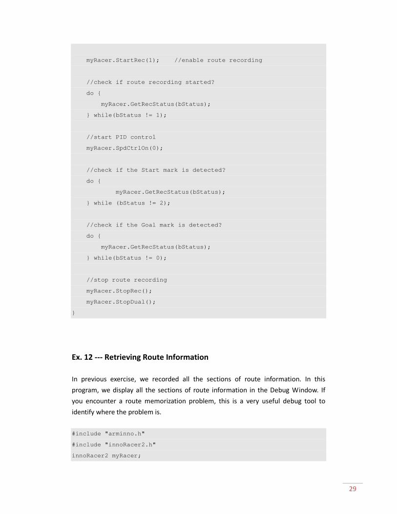
myRacer.StartRec(1); //enable route recording
//check if route recording started?
do {
myRacer.GetRecStatus(bStatus);
} while(bStatus != 1);
//start PID control
myRacer.SpdCtrlOn(0);
//check if the Start mark is detected?
do {
myRacer.GetRecStatus(bStatus);
} while (bStatus != 2);
//check if the Goal mark is detected?
do {
myRacer.GetRecStatus(bStatus);
} while(bStatus != 0);
//stop route recording
myRacer.StopRec();
myRacer.StopDual();
}
Ex. 12 --- Retrieving Route Information
In previous exercise, we recorded all the sections of route information. In this
program, we display all the sections of route information in the Debug Window. If
you encounter a route memorization problem, this is a very useful debug tool to
identify where the problem is.
#include "arminno.h"
#include "innoRacer2.h"
innoRacer2 myRacer;

30
int main(void)
{
unsigned char SecCnt;
short L, R, MaxAcc, AvgAcc, MaxGyro, AvgGyro;
myRacer.GetTotalSecCnt(SecCnt); //¨get total section number
printf("Count = %d\r\n", SecCnt);
printf(" \t L \t R \tMaxAcc\tAvgAcc\tMaxGyro\tAvgGyro\r\n");
//read information sequentially
for(unsigned char i = 0 ; i < SecCnt ; i++) {
myRacer.GetSecLen(i, L, R);
myRacer.GetSecMaxAyGz(i, MaxAcc, MaxGyro);
myRacer.GetSecAvgAyGz(i, AvgAcc, AvgGyro);
printf("%3d\t%4d\t%4d\t%6d\t%6d\t%6d\t%6d\r\n", i, L, R, MaxAcc,
AvgAcc, MaxGyro, AvgGyro);
}
}
Ex. 13 --- Acceleration
We know how to record the information of all the sections of the route. Now we can
start to use this information to speed up our InnoRacerTM
2S. There are many
different approaches or strategies to speed up the InnoRacerTM
2S. In this program,
we learn the basics of acceleration according to the route information. The
InnoRacerTM
2S starts to accelerate after the Start mark is detected and stops.
#include "arminno.h"
#include "innoRacer2.h"
innoRacer2 myRacer;
#define FREQ_CTRL 4
#define CROSS_COUNT 14 // intersection bias
#define STOP_TACH 100
const short NORMAL_SPEED_L = 130;

31
const short NORMAL_SPEED_R = 130;
const short CRAZY_SPEED_L = 150;
const short CRAZY_SPEED_R = 150;
//------------------------------------------------------
// set PID values
//------------------------------------------------------
const short kP=22;
const short kI=0;
const short kD=240;
//------------------------------------------------------
// set error values
//------------------------------------------------------
#define PID_SCALAR 4
const short sStrErr[]={18,30,48,78,126,144,330,534};
unsigned char bStatus;
unsigned char bIR;
unsigned short LenL,LenR;
//------------------------------------------------------
// module initialization
//------------------------------------------------------
void Init(void)
{
//set PID values
myRacer.SetCtrlFreq(FREQ_CTRL);
myRacer.SetP(kP);
myRacer.SetI(kI);
myRacer.SetD(kD);
myRacer.SetScalar(PID_SCALAR);
// set the mid speed
myRacer.SetStraight(NORMAL_SPEED_L,NORMAL_SPEED_R);
// set the Analog mode
myRacer.SetIrMode(1);
//set error values
myRacer.SetErrScale(sStrErr[0], sStrErr[1], sStrErr[2], sStrErr[3],

32
sStrErr[4], sStrErr[5], sStrErr[6], sStrErr[7]);
myRacer.SetCrossCount(CROSS_COUNT);
//set motor dead zone
myRacer.SetMotorDeadZone(136);
}
int main(void)
{
Init();
myRacer.AutoBeep(1); //enable auto beep
//check if in central position
do {
myRacer.GetIr(bIR);
} while((bIR & 0x04) == 0x00);
myRacer.BuzzerOn();
Pause(20000);
myRacer.StartRec(1); // analog mode
//check if route recording started?
do {
myRacer.GetRecStatus(bStatus);
} while(bStatus != 1);
myRacer.SpdCtrlOn(0); //enable PID control
// check if Goal mark is detected?
do {
myRacer.GetRecStatus(bStatus);
} while (bStatus != 2);
// set higher speed
myRacer.SetStraight(CRAZY_SPEED_L,CRAZY_SPEED_R);
do{
myRacer.GetTotalLen(LenL,LenR);
}while(LenL < STOP_TACH);

33
//stop route recording
myRacer.StopRec();
myRacer.StopDual();
}
Ex. 14 --- Ready to Go
Finally, we add more functions in this program. By pressing button 0 to select
recording mode, InnoRacerTM
2S will execute route memorization run. After the
route is successfully recorded, press button 1 and InnoRacerTM
2S will execute racing
run. If you encounter problem during the runs, connect InnoRacerTM
2S to your
development environment and press button 2 to display all the route records for
your analysis. Now you are almost ready to put your InnoRacerTM
2S line follower on
the racing course to compete. After learning all the basics required, try to develop
your own racing strategies and have fun!
#include "arminno.h"
#include "innoRacer2.h"
innoRacer2 myRacer;
#define FREQ_CTRL 4
#define CROSS_COUNT 4 // intersection bias
const short NORMAL_SPEED_L = 130;
const short NORMAL_SPEED_R = 130;
const short CRAZY_SPEED_L = 400;
const short CRAZY_SPEED_R = 400;
const short STOP_SPEED_L = 0;
const short STOP_SPEED_R = 0;
const short kP=22;
const short kI=0;
const short kD=240;

34
const float StopLevel = 3;
const short soffset = 136;
//------------------------------------------------------
// set error values
//------------------------------------------------------
#define PID_SCALAR 4
const short sStrErr[]={18,30,48,78,126,144,330,534};
//------------------------------------------------------
// Accelerating parameters
//------------------------------------------------------
const short STOP_TACH = 200;
const short ACC_TACH = 50;
const short HOLD_STOP = 100;
const short ACC_G = 100;
unsigned char bStatus;
unsigned char bIR;
unsigned char bCnt, bNxtCnt, bLevel;
short iAy, iGz;
short wSecLenL, wSecLenR, wStopLen,wPreLen;
short wCurCntL, wCurCntR;
//------------------------------------------------------
// module initialization
//------------------------------------------------------
void Init(void)
{
//set PID values
myRacer.SetCtrlFreq(FREQ_CTRL);
myRacer.SetP(kP);
myRacer.SetI(kI);
myRacer.SetD(kD);
myRacer.SetScalar(PID_SCALAR);
myRacer.SetOutsideMode(1);
// set error values

35
myRacer.SetErrScale(sStrErr[0], sStrErr[1], sStrErr[2], sStrErr[3],
sStrErr[4], sStrErr[5], sStrErr[6], sStrErr[7]);
//set speed related values
myRacer.SetStraight(NORMAL_SPEED_L,NORMAL_SPEED_R);
myRacer.SetCrossCount(CROSS_COUNT);
myRacer.SetIrMode(1);
myRacer.SetIrMask(1);
myRacer.SetLineColor(0);
myRacer. SetMotorDeadZone(soffset);
}
//--------------------------------------------------------
// route recording function
//--------------------------------------------------------
void REC_ROUTE(void)
{
myRacer.AutoBeep(1); //enable auto beep
//check if in central position
do {
myRacer.GetIr(bIR);
} while((bIR & 0x04) == 0x00);
myRacer.BuzzerOn();
Pause(20000);
myRacer.StartRec(1); // analog mode
//check if route recording started?
do {
myRacer.GetRecStatus(bStatus);
} while(bStatus != 1);
myRacer.SpdCtrlOn(0); //enable PID control
// check if Goal mark is detected?

36
do {
myRacer.GetRecStatus(bStatus);
} while (bStatus != 2);
// check if Goal mark is detected?
do {
myRacer.GetRecStatus(bStatus);
} while(bStatus != 0);
//stop route recording
myRacer.StopRec();
Pause(3000);
myRacer.StopDual();
}
void CheckCount(short wTarCntL)
{
short wCurCntL, wCurCntR;
do {
myRacer.GetCurSecTach(wCurCntL, wCurCntR);
} while(wCurCntL < wTarCntL);
}
//--------------------------------------------------------
// racing function
//--------------------------------------------------------
void RACE_ROUTE(void)
{
short SecLen[256], AvgG[256];
unsigned char Cnt,bCrazy;
//check if in central position
do {
myRacer.GetIr(bIR);
} while((bIR & 0x04) == 0x00);
myRacer.BuzzerOn();
Pause(20000);

37
bCnt = 0;
bNxtCnt = 0;
wStopLen = 0;
bCrazy = 0;
myRacer.GetSecAvgAyGz(bNxtCnt, iAy, iGz);
myRacer.GetSecLen(bNxtCnt, wSecLenL, wSecLenR);
myRacer.AutoBeep(0);
myRacer.StartRec(0);
//check if route recording started?
do {
myRacer.GetRecStatus(bStatus);
} while(bStatus != 1);
myRacer.SetStraight(NORMAL_SPEED_L,NORMAL_SPEED_R);
myRacer.SpdCtrlOn(0);
// check if Goal mark is detected?
do {
myRacer.GetRecStatus(bStatus);
} while(bStatus != 2);
// ¨check straight route to use high speed
do {
myRacer.GetSecCnt(bCnt);
if (bNxtCnt==bCnt)
{
bNxtCnt ++;
if((iAy < ACC_G) && (iAy > -ACC_G) && (wStopLen > 0))
{
myRacer.SetStraight(CRAZY_SPEED_L,CRAZY_SPEED_R);
CheckCount(wStopLen);
myRacer.SetStraight(STOP_SPEED_L,STOP_SPEED_R);
Pause(HOLD_STOP);
myRacer.SetStraight(NORMAL_SPEED_L,NORMAL_SPEED_R);

38
}
myRacer.GetSecAvgAyGz(bNxtCnt, iAy, iGz);
myRacer.GetSecLen(bNxtCnt, wSecLenL, wSecLenR);
if (wSecLenL >ACC_TACH)
{
wStopLen = wSecLenL - STOP_TACH;
}
else
{
wStopLen = 0;
}
}
myRacer.GetRecStatus(bStatus);
} while(bStatus != 0);
Pause(1500);
myRacer.BrakeDual();
}
void PrintData()
{
unsigned char SecCnt;
short L, R, MaxAcc, AvgAcc, MaxGyro, AvgGyro;
myRacer.GetTotalSecCnt(SecCnt);
printf("Count = %d\r\n", SecCnt);
printf(" \t L \t R \tMaxAcc\tAvgAcc\tMaxGyro\tAvgGyro\r\n");
for(unsigned char i = 0 ; i < SecCnt ; i++)
{
myRacer.GetSecLen(i, L, R);
myRacer.GetSecMaxAyGz(i, MaxAcc, MaxGyro);
myRacer.GetSecAvgAyGz(i, AvgAcc, AvgGyro);
printf("%3d\t%4d\t%4d\t%6d\t%6d\t%6d\t%6d\r\n", i, L, R,
MaxAcc, AvgAcc, MaxGyro, AvgGyro);
}
}
int main(void)

39
{
for(int i = 0 ; i < 3 ;i++) {
myRacer.LedOn();
Pause(2000);
myRacer.LedOff();
Pause(2000);
}
Init();
while(1) {
//check if button is pressed
if(myRacer.GetButton0State() == 0) {
myRacer.Led0On();
REC_ROUTE();
myRacer.LedOff();
}
else if(myRacer.GetButton1State() == 0) {
myRacer.Led1On();
RACE_ROUTE();
myRacer.LedOff();
}
else if(myRacer.GetButton2State() == 0) {
myRacer.Led2On();
PrintData();
myRacer.Led2Off();
}
}
}

40
Appendix B --- Sample Course
This is a sample course with a minimum curvature of 10cm. The actual size is 180 cm
x 400 cm. There could be different racing games with similar rules. Refer to their
official document and modify the course and program accordingly.


