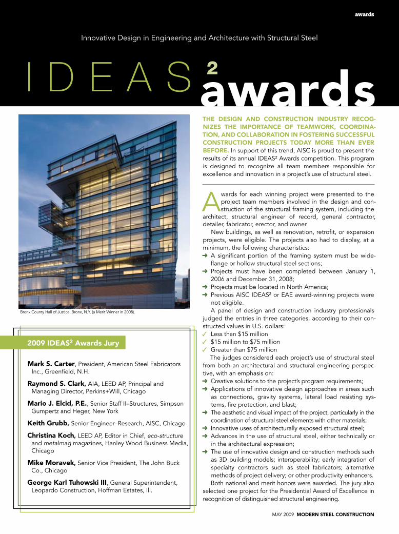
MAY 2009 MODERN STEEL CONSTRUCTION awards A wards for each winning project were presented to the project team members involved in the design and con- struction of the structural framing system, including the architect, structural engineer of record, general contractor, detailer, fabricator, erector, and owner. New buildings, as well as renovation, retrofit, or expansion projects, were eligible. The projects also had to display, at a minimum, the following characteristics: ➜ A significant portion of the framing system must be wide- flange or hollow structural steel sections; ➜ Projects must have been completed between January 1, 2006 and December 31, 2008; ➜ Projects must be located in North America; ➜ Previous AISC IDEAS² or EAE award-winning projects were not eligible. A panel of design and construction industry professionals judged the entries in three categories, according to their con- structed values in U.S. dollars: ✓ Less than $15 million ✓ $15 million to $75 million ✓ Greater than $75 million The judges considered each project’s use of structural steel from both an architectural and structural engineering perspec- tive, with an emphasis on: ➜ Creative solutions to the project’s program requirements; ➜ Applications of innovative design approaches in areas such as connections, gravity systems, lateral load resisting sys- tems, fire protection, and blast; ➜ The aesthetic and visual impact of the project, particularly in the coordination of structural steel elements with other materials; ➜ Innovative uses of architecturally exposed structural steel; ➜ Advances in the use of structural steel, either technically or in the architectural expression; ➜ The use of innovative design and construction methods such as 3D building models; interoperability; early integration of specialty contractors such as steel fabricators; alternative methods of project delivery; or other productivity enhancers. Both national and merit honors were awarded. The jury also selected one project for the Presidential Award of Excellence in recognition of distinguished structural engineering. Innovative Design in Engineering and Architecture with Structural Steel THE DESIGN AND CONSTRUCTION INDUSTRY RECOG- NIZES THE IMPORTANCE OF TEAMWORK, COORDINA- TION, AND COLLABORATION IN FOSTERING SUCCESSFUL CONSTRUCTION PROJECTS TODAY MORE THAN EVER BEFORE. In support of this trend, AISC is proud to present the results of its annual IDEAS² Awards competition. This program is designed to recognize all team members responsible for excellence and innovation in a project’s use of structural steel. awards IDEAS 2 2009 IDEAS 2 Awards Jury Mark S. Carter, President, American Steel Fabricators Inc., Greenfield, N.H. Raymond S. Clark, AIA, LEED AP, Principal and Managing Director, Perkins+Will, Chicago Mario J. Elcid, P.E., Senior Staff II–Structures, Simpson Gumpertz and Heger, New York Keith Grubb, Senior Engineer–Research, AISC, Chicago Christina Koch, LEED AP, Editor in Chief, eco-structure and metalmag magazines, Hanley Wood Business Media, Chicago Mike Moravek, Senior Vice President, The John Buck Co., Chicago George Karl Tuhowski III, General Superintendent, Leopardo Construction, Hoffman Estates, Ill. Bronx County Hall of Justice, Bronx, N.Y. (a Merit Winner in 2008).
Transcript
may 2009 MODERN STEEL CONSTRUCTION
awardsawards
awards for each winning project were presented to the project team members involved in the design and con-struction of the structural framing system, including the
architect, structural engineer of record, general contractor, detailer, fabricator, erector, and owner.
New buildings, as well as renovation, retrofit, or expansion projects, were eligible. The projects also had to display, at a minimum, the following characteristics:➜ a significant portion of the framing system must be wide-
flange or hollow structural steel sections;➜ Projects must have been completed between January 1,
2006 and December 31, 2008;➜ Projects must be located in North america;➜ Previous aISC IDEaS² or EaE award-winning projects were
not eligible.a panel of design and construction industry professionals
judged the entries in three categories, according to their con-structed values in U.S. dollars:✓ Less than $15 million✓ $15 million to $75 million✓ Greater than $75 million
The judges considered each project’s use of structural steel from both an architectural and structural engineering perspec-tive, with an emphasis on:➜ Creative solutions to the project’s program requirements;➜ applications of innovative design approaches in areas such
as connections, gravity systems, lateral load resisting sys-tems, fire protection, and blast;
➜ The aesthetic and visual impact of the project, particularly in the coordination of structural steel elements with other materials;
➜ Innovative uses of architecturally exposed structural steel;➜ advances in the use of structural steel, either technically or
in the architectural expression;➜ The use of innovative design and construction methods such
as 3D building models; interoperability; early integration of specialty contractors such as steel fabricators; alternative methods of project delivery; or other productivity enhancers.
Both national and merit honors were awarded. The jury also selected one project for the Presidential award of Excellence in recognition of distinguished structural engineering.
Innovative Design in Engineering and architecture with Structural Steel
ThE DESIgN aND CONSTRUCTION INDUSTRy RECOg-NIzES ThE IMpORTaNCE Of TEaMwORk, COORDINa-TION, aND COLLabORaTION IN fOSTERINg SUCCESSfUL CONSTRUCTION pROjECTS TODay MORE ThaN EvER bEfORE. In support of this trend, aISC is proud to present the results of its annual IDEaS² awards competition. This program is designed to recognize all team members responsible for excellence and innovation in a project’s use of structural steel.
awardsI D E A S 2
2009 IDEaS2 awards jury
Mark S. Carter, President, american Steel Fabricators Inc., Greenfield, N.H.
Raymond S. Clark, aIa, LEED aP, Principal and managing Director, Perkins+Will, Chicago
Mario j. Elcid, p.E., Senior Staff II–Structures, Simpson Gumpertz and Heger, New york
keith grubb, Senior Engineer–Research, aISC, Chicago
Christina koch, LEED aP, Editor in Chief, eco-structure and metalmag magazines, Hanley Wood Business media, Chicago
Mike Moravek, Senior Vice President, The John Buck Co., Chicago
george karl Tuhowski III, General Superintendent, Leopardo Construction, Hoffman Estates, Ill.
Bronx County Hall of Justice, Bronx, N.y. (a merit Winner in 2008).
MODERN STEEL CONSTRUCTION may 2009
awards
National winner—Under $15M aRMSTRONg OIL & gaS—DENvER
Ownerarmstrong Oil and Gas, Denver
architectLake l Flato architects, Inc., San antonio
associate architectBothwell Davis George architects, Denver
T his adaptive reuse of an early 1900s industrial machine shop has helped to launch a new identity for an estab-lished local business—armstrong Oil and Gas—in lower
downtown Denver (LoDo). Charged with bringing new life to an underused building, the design team planned the enclosed program around existing elements and created generous, so-phisticated spaces filled with daylight, natural ventilation and views of the Denver skyline.
The existing corrugated steel roof over the main second floor office had deteriorated over the years due to water in-filtration and was replaced with corrugated zinc roofing. The original structure consisted of four gabled steel trusses with riv-eted connections, with wood framing spanning between.
Two of the trusses were salvaged, while two were replaced with new trusses using double steel angle members to repli-cate the historic trusses, but with welded connections to dif-ferentiate between the old and new. The gable trusses are ap-proximately 24 ft wide and 6 ft tall. The top and bottom chords are double 3×3×¼ steel angles, and the diagonals are 2×2×¼ or 3×3×¼ angles. Sawtooth trusses over the second-floor office area were built with the same-size members. The wood framing was replaced with an 18-gauge steel deck clear spanning be-tween trusses, and the existing cupola vent was replaced with a steel-framed and glazed monitor to provide additional light and ventilation to the office.
To create the centralized courtyard, which now provides abun-dant natural light and ventilation to all of the interior spaces, the
center section of the original roof was stripped away. addition-ally, existing heavy timber roof beams and wood decking was removed to express the steel frame, and the wood was repur-posed into many of the custom-fabricated interior furnishings.
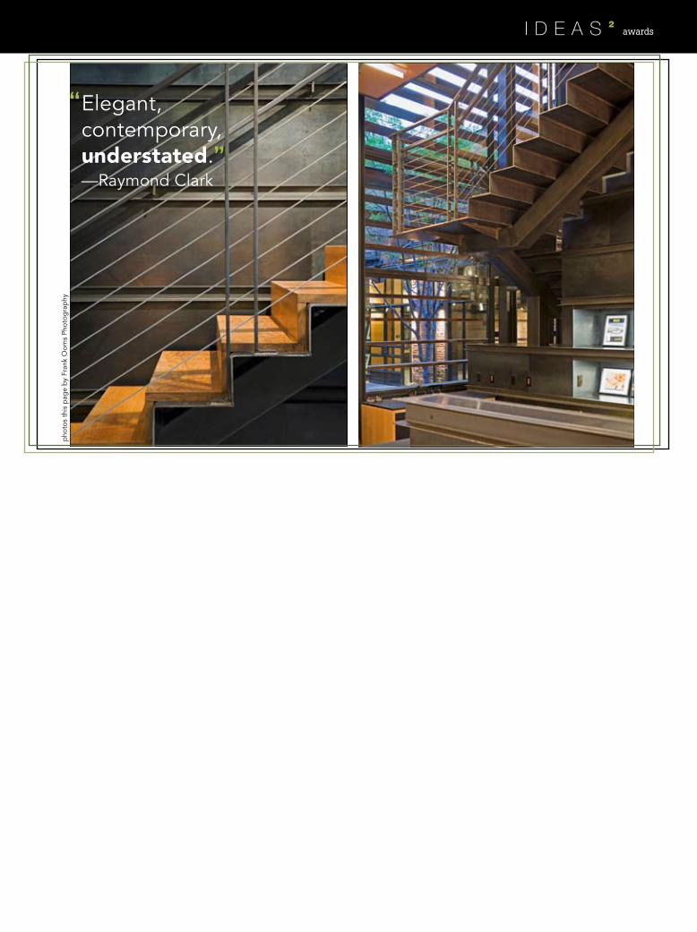
Primary vertical circulation is provided by two folded steel plate stairs—using ¼-in. plate—that cantilever off of a central tube structure. a new catwalk made of steel angles and bar grating is suspended on steel rods from the existing roof fram-ing and links the upper lounge and second-floor offices through the double-height space of the “war room.”
The mixture of old and new exposed materials impressed juror Raymond S. Clark, who praised the building for its “excel-lent combination of ornamental steelwork, structural elements, and refurbishment and reuse of historical steel members.”
The building was upgraded for earthquake and wind loads by integrating new brace frames and creating moment-resisting rigid frames from the new steel columns and trusses that form the saw-tooth roof. Where new openings were made in the existing brick walls, the lintel was created by sandwiching the head of the opening with a steel channel on each side, secured in place with through-bolts. The expressed lintel not only contributes to the his-toric aesthetic of the space, but also allowed for a safe and eco-nomic construction sequence; by installing the lintel first, the brick could be removed and the need for temporary shoring avoided.
The building maintains its existing shell and structure, elimi-nating tons of waste from local landfills while preserving a ven-erable landmark in downtown Denver.
photos this p
age b
y Frank Oom
s Photograp
hy
awards
Elegant,
—Raymond Clark”
“contemporary,understated.
pho
tos
this
pag
e b
y Fr
ank
Oom
s Ph
otog
rap
hy
MODERN STEEL CONSTRUCTION may 2009
awards
Merit award—Under $15M hOLOCaUST aND hUMaN RIghTS CENTER Of MaINE—aUgUSTa, MaINE
—George Tuhowski”
“Striking aestheticallyand an excellent example
of the design flexibilitythat steel can provide.
OwnerUniversity of maine at augusta
architectShepley Bulfinch Richardson and abbott, Boston
Structural EngineerSimpson Gumpertz and Heger, Inc., Waltham, mass.
general ContractorWright–Ryan Construction, Inc., Portland, maine
The michael Klahr Center (mKC), the new home of the Holocaust and Human Rights Center of maine (HHRC), is a 6,300-sq.-ft, one-story building on
the campus of the University of maine at augusta. The massing for the mKC creates a bold visual ex-
position of the HHRC’s mission to educate future gen-erations about the Holocaust and other human rights abuses. Four flower-like petals spring forth from the ground around that central focal point, reminding visi-tors of the rebirth of freedom after the long, hard winter of World War II.
Because the HHRC was charged with building the mKC on a total budget of only $1.8 million, structural steel proved essential to realizing the architect’s vision for the building. although the sculptural forms of the petals could have been well-suited to cast-in-place concrete, the expense of the curved formwork and the construction schedule demanded a different structural system. In response to the sculptural demands of the petal architecture, Simpson Gumpertz and Heger, the structural engineer for the project, developed a struc-tural system consisting of a grid of HSS sections using curved HSS8×8s as the ribs along “meridians” of the spherical petal sections and straight HSS4×4s along “parallels” of the petals.
These grids, moment connected in-plane and stra-tegically braced in certain bays, enable the petal struc-tures to act as shells. Selecting steel for the petals al-lowed for portions of the petals to be shop-fabricated, speeding up construction considerably.
The petal structure made quite an impression on the jury. George Tuhowski called the project “striking aesthetically and an excellent example of the design flexibility that steel can provide,” while juror Raymond Clark commented on the “excellent detailing and use of flowing curved elements to achieve what one would expect to be executed in concrete.”
For more on this project, see “Blooming Knowl-edge” in the January 2009 issue of mSC, available in the archives section at www.modernsteel.com.
photos this page by Esto Photography
may 2009 MODERN STEEL CONSTRUCTION
awards
Merit award—Under $15M RayMOND aND SUSaN bROChSTEIN pavILION—hOUSTON
This design is—mark Carterabsolutely delightful.”
“
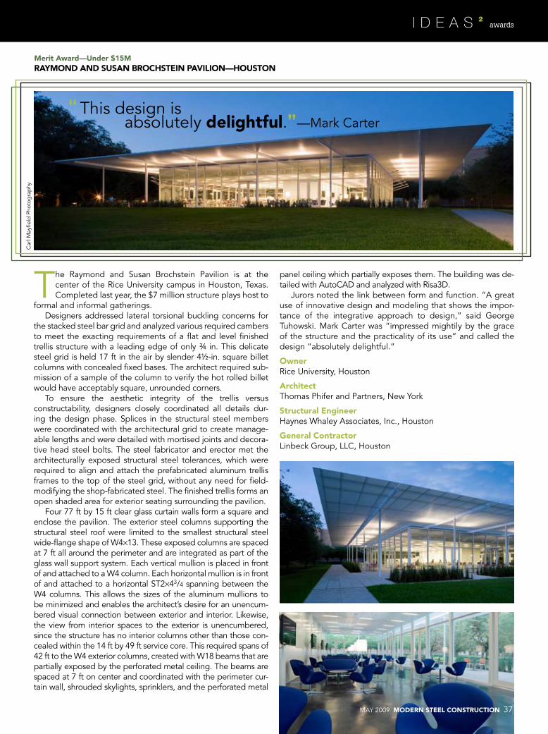
The Raymond and Susan Brochstein Pavilion is at the center of the Rice University campus in Houston, Texas. Completed last year, the $7 million structure plays host to
formal and informal gatherings.Designers addressed lateral torsional buckling concerns for
the stacked steel bar grid and analyzed various required cambers to meet the exacting requirements of a flat and level finished trellis structure with a leading edge of only ¾ in. This delicate steel grid is held 17 ft in the air by slender 4½-in. square billet columns with concealed fixed bases. The architect required sub-mission of a sample of the column to verify the hot rolled billet would have acceptably square, unrounded corners.
To ensure the aesthetic integrity of the trellis versus constructability, designers closely coordinated all details dur-ing the design phase. Splices in the structural steel members were coordinated with the architectural grid to create manage-able lengths and were detailed with mortised joints and decora-tive head steel bolts. The steel fabricator and erector met the architecturally exposed structural steel tolerances, which were required to align and attach the prefabricated aluminum trellis frames to the top of the steel grid, without any need for field-modifying the shop-fabricated steel. The finished trellis forms an open shaded area for exterior seating surrounding the pavilion.
Four 77 ft by 15 ft clear glass curtain walls form a square and enclose the pavilion. The exterior steel columns supporting the structural steel roof were limited to the smallest structural steel wide-flange shape of W4×13. These exposed columns are spaced at 7 ft all around the perimeter and are integrated as part of the glass wall support system. Each vertical mullion is placed in front of and attached to a W4 column. Each horizontal mullion is in front of and attached to a horizontal ST2×43/4 spanning between the W4 columns. This allows the sizes of the aluminum mullions to be minimized and enables the architect’s desire for an unencum-bered visual connection between exterior and interior. Likewise, the view from interior spaces to the exterior is unencumbered, since the structure has no interior columns other than those con-cealed within the 14 ft by 49 ft service core. This required spans of 42 ft to the W4 exterior columns, created with W18 beams that are partially exposed by the perforated metal ceiling. The beams are spaced at 7 ft on center and coordinated with the perimeter cur-tain wall, shrouded skylights, sprinklers, and the perforated metal
panel ceiling which partially exposes them. The building was de-tailed with autoCaD and analyzed with Risa3D.
Jurors noted the link between form and function. “a great use of innovative design and modeling that shows the impor-tance of the integrative approach to design,” said George Tuhowski. mark Carter was “impressed mightily by the grace of the structure and the practicality of its use” and called the design “absolutely delightful.”
The museum of Flight in Seattle is one of the largest air and space museums in the world, attracting
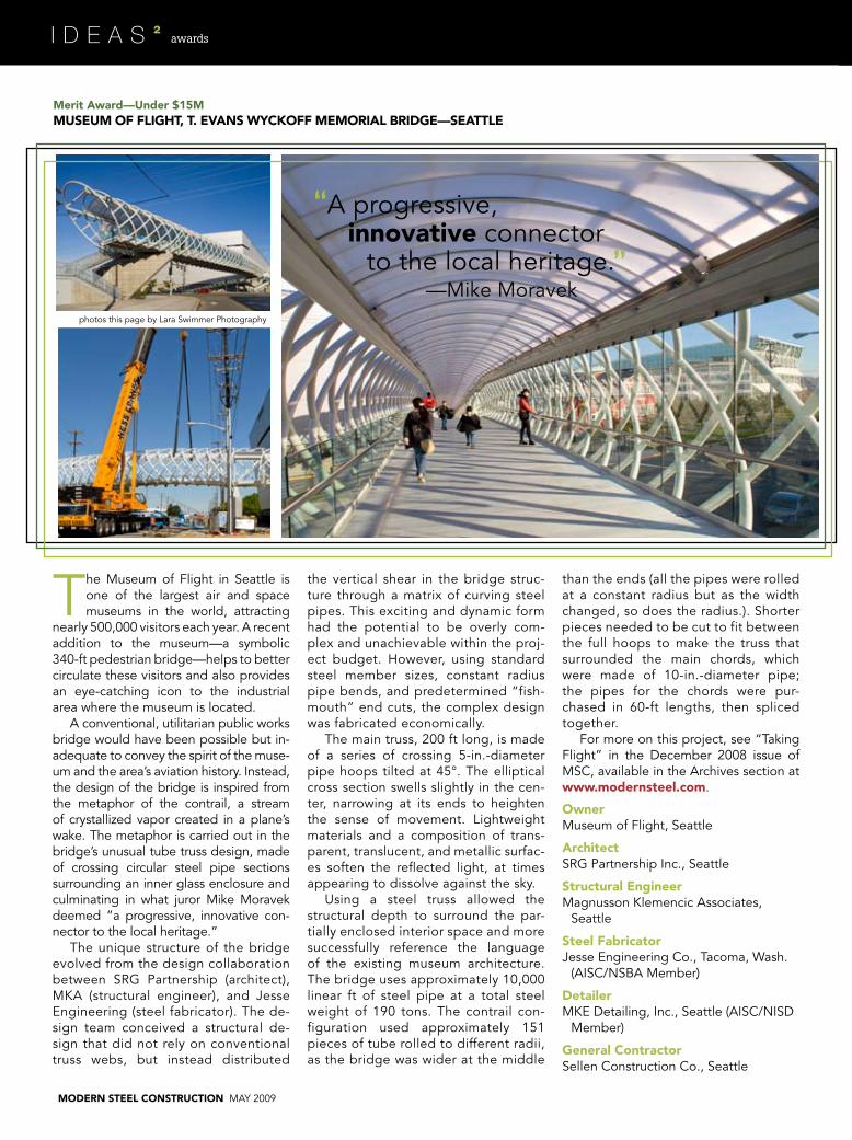
nearly 500,000 visitors each year. a recent addition to the museum—a symbolic 340-ft pedestrian bridge—helps to better circulate these visitors and also provides an eye-catching icon to the industrial area where the museum is located.
a conventional, utilitarian public works bridge would have been possible but in-adequate to convey the spirit of the muse-um and the area’s aviation history. Instead, the design of the bridge is inspired from the metaphor of the contrail, a stream of crystallized vapor created in a plane’s wake. The metaphor is carried out in the bridge’s unusual tube truss design, made of crossing circular steel pipe sections surrounding an inner glass enclosure and culminating in what juror mike moravek deemed “a progressive, innovative con-nector to the local heritage.”
The unique structure of the bridge evolved from the design collaboration between SRG Partnership (architect), mKa (structural engineer), and Jesse Engineering (steel fabricator). The de-sign team conceived a structural de-sign that did not rely on conventional truss webs, but instead distributed
the vertical shear in the bridge struc-ture through a matrix of curving steel pipes. This exciting and dynamic form had the potential to be overly com-plex and unachievable within the proj-ect budget. However, using standard steel member sizes, constant radius pipe bends, and predetermined “fish-mouth” end cuts, the complex design was fabricated economically.
The main truss, 200 ft long, is made of a series of crossing 5-in.-diameter pipe hoops tilted at 45°. The elliptical cross section swells slightly in the cen-ter, narrowing at its ends to heighten the sense of movement. Lightweight materials and a composition of trans-parent, translucent, and metallic surfac-es soften the reflected light, at times appearing to dissolve against the sky.
Using a steel truss allowed the structural depth to surround the par-tially enclosed interior space and more successfully reference the language of the existing museum architecture. The bridge uses approximately 10,000 linear ft of steel pipe at a total steel weight of 190 tons. The contrail con-figuration used approximately 151 pieces of tube rolled to different radii, as the bridge was wider at the middle
than the ends (all the pipes were rolled at a constant radius but as the width changed, so does the radius.). Shorter pieces needed to be cut to fit between the full hoops to make the truss that surrounded the main chords, which were made of 10-in.-diameter pipe; the pipes for the chords were pur-chased in 60-ft lengths, then spliced together.
For more on this project, see “Taking Flight” in the December 2008 issue of mSC, available in the archives section at www.modernsteel.com.
Merit award—Under $15M MUSEUM Of fLIghT, T. EvaNS wyCkOff MEMORIaL bRIDgE—SEaTTLE
general ContractorSellen Construction Co., Seattle
innovative connectora progressive,
to the local heritage.—mike moravek
”
“
photos this page by Lara Swimmer Photography
MODERN STEEL CONSTRUCTION may 2009
awards
[This page left blank intentionally to preserve page flow.]
MODERN STEEL CONSTRUCTION may 2009
awards
National award—$15M to $75M pOOL/ICE RINk aT fLUShINg MEaDOwS CORONa paRk—fLUShINg, NEw yORk
—mario Elcid
The flexibility...isvery creative.”
“
While New york never realized its dreams of becoming the host city for the 2012 Olym-
pic Games, it did get a nice pool as a result of being a candidate city. al-though planned as a recreation and community competition facility, the design of the new pool at Corona Park in Flushing, N.y. was commissioned at the time when New york was in the hunt for the 2012 Games.
at the time, New york had limited indoor swimming facilities, and the new natatorium was programmed as the venue for water polo and synchro-nized swimming competitions. as such, the building design solution had to be economical both with respect to initial building cost as well as operational costs after the Olympic events. as part of this goal the building volume was to be kept to a minimum to bring down heating and cooling costs. To achieve this goal and accommodate the possi-bility of the Olympic seating, a cable-stayed suspended roof structure was chosen for the building, which also contains an ice rink.
Bracing members in the wall stabi-lize the hinge between the masts above the roof and their support columns, as well as provide part of the lateral sup-port for the building. For the façade cladding, insulated precast panels were specified. Their mass is used to
resist any uplift loads that could result from unbalanced roof loads transmit-ted through the cables to the wall at the ice rink. Lateral bracings com-posed of HSS sections are provided in the end and center transverse walls of the building, as well as the exterior sidewalls of the ice rink.
The roof supporting masts each anchor twelve 3-in. structural strand cables, of which six support part of the pool roof and six part of the ice rink roof. The roof in elevation is waved with the high elevation over the pool to ac-commodate the sight lines for the pro-posed outside seating at an Olympic event. The low elevation over the ice rink was designed to keep the building volume to a minimum for energy use considerations. The roof cables are anchored to W36×300, spaced 30 ft apart and span the length of the roof, equilibrating the compression compo-nent resulting from the cable forces. These members are the deepest of the roof structure.
The roof deck is comprised of 2-in.-thick lightweight concrete chan-nel planks. These are exposed to the interior and were employed in lieu of metal deck in light of the corrosive pool environment. They also provide sufficient dead weight to resist wind uplift on the roof. The connections of the roof plank were designed to ac-
commodate the movements of the cable-stayed roof, and no concrete topping was specified for the planks. as a result, the roof planks do not provide a shear diaphragm to distrib-ute lateral loads to the wall bracing. Instead, HSS members address shear in the roof surface, and these tie into the bracing in the walls. The structure above the pool deck consists of steel columns and girts, which support the precast insulated wall panels as well as the glass façades that face south.
Because the roof structure equili-brates the horizontal force compo-nents of the roof cables, no expansion joint is used in the 450-ft-long struc-ture. Thus the lateral bracing is con-centrated and configured in such a way that it does not constrain the building against thermal movements but still provides resistance to seismic and wind lateral loads. It could not be in the pool section where the wall fram-ing is to be removed for clear viewing of the swimming events, thus it had to be placed in the ice rink section. The interaction between the precast wall cladding and the thermal movements of the steel required careful design of the precast concrete connections so that the precast would not restrain the steel movements.
mario Elcid praised the “great in-novative roof structure, “noting that
general ContractorBovis Lend Lease LmB, Inc., New york
its “flexibility to accommodate addi-tional seating for an Olympic event is very creative in saving on unnecessary structural steel.”
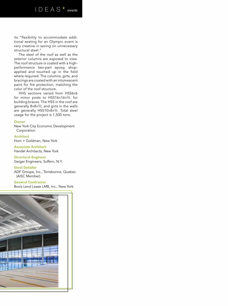
The steel of the roof as well as the exterior columns are exposed to view. The roof structure is coated with a high-performance two-part epoxy, shop-applied and touched up in the field where required. The columns, girts, and bracings are coated with an intumescent paint for fire protection, matching the color of the roof structure.
HHS sections varied from HSS6×6 for minor posts to HSS16×16×3∕8. for building braces. The HSS in the roof are generally 8×8×3∕8, and girts in the walls are generally HSS10×8×3∕8. Total steel usage for the project is 1,500 tons.
awards
MODERN STEEL CONSTRUCTION may 2009
awards
Merit award—$15M to $75M aRIzONa STaTE UNIvERSITy pOLyTEChNIC CLaSSROOM bUILDINgS—MESa, aRIzONa
Innovative,environmental, efficient.
—Raymond Clark”
“
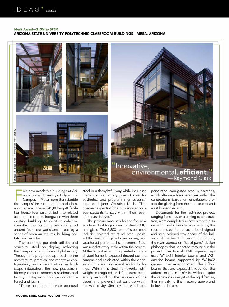
Five new academic buildings at ari-zona State University’s Polytechnic Campus in mesa more than double
the campus’ instructional lab and class-room space. These 245,000-sq.-ft facili-ties house four distinct but interrelated academic colleges. Integrated with three existing buildings to create a cohesive complex, the buildings are configured around four courtyards and linked by a series of open-air atriums, building por-tals, and arcades.
The buildings put their utilities and structural steel on display, reflecting the campus’ straightforward philosophy. Through this pragmatic approach to the architecture, practical and repetitive con-figuration, and concentration on land-scape integration, the new pedestrian-friendly campus promotes students and faculty to stay on school grounds to in-teract and learn.
“These buildings integrate structural
steel in a thoughtful way while including many complementary uses of steel for aesthetics and programming reasons,” expressed juror Christina Koch. “The open-air aspects of the buildings encour-age students to stay within them even after class is over.”
The primary materials for the five new academic buildings consist of steel, CmU, and glass. The 2,200 tons of steel used include: painted structural steel, paint-ed flat and corrugated steel siding, and weathered perforated sun screens. Steel was used at every scale within the project. at the largest extent, the painted structur-al steel frame is exposed throughout the campus and celebrated within the open-air atriums and on several anchor build-ings. Within this steel framework, light-weight corrugated and flat-seam metal siding respond to the aridness of the desert and prevent heat build-up within the wall cavity. Similarly, the weathered
perforated corrugated steel sunscreens, which alternate transparencies within the corrugations based on orientation, pro-tect the glazing from the intense east and west low-angled sun.
Documents for the fast-track project, ranging from master planning to construc-tion, were completed in seven months. In order to meet schedule requirements, the structural steel frame had to be designed and steel ordered way ahead of the bal-ance of the building design. To do this, the team agreed on “kit-of-parts” design philosophy that repeated throughout the project. The typical 30-ft. square bays used W16×31 interior beams and W21 exterior beams supported by W24×62 girders. The exterior 21-in. deep floor beams that are exposed throughout the atriums maintain a 6½-in. width despite the variation in weight at the rigid frames, thus simplifying the masonry above and below the beams.
pho
tos
this
pag
e b
y B
ill T
imm
erm
an P
hoto
gra
phy
awards
Ownerarizona State University, Tempe, ariz.
associate architectLake|Flato architects, San antonio
Steel fabricator, Erector, and DetailerSchuff Steel Company, Phoenix (aISC
member)
general ContractorDPR Construction, Phoenix
after the structural frame was estab-lished and steel ordered, the building design continued with the goal of work-ing around the steel frame already es-tablished. Steel joists were used at the roof of the three-story structures except at mechanical equipment where steel beams were substituted. The two-story structures featured vaulted roofs framed with exposed steel beams. To manage the cost of architecturally exposed struc-tural steel used in the project, all aESS members and connections were identi-fied on the structural plans. all exposed edges, bolts, welds and copes were dis-cussed with the steel fabricator, Schuff Steel, who was selected early in design to work in a design-assist capacity.
although typical BIm software was not used on the project, all of the design meetings used a combination of Sketch-Up, Ram Structural System, and Tekla Structures to work through design issues. When DPR, the contractor, and Schuff determined that the desired suspended walkway system would push erection costs outside the budget, structural engineer Paragon and Schuff traded Ram analysis models back and forth to quickly design and price options. a cantilevered walk-way system was selected and brought the project back in line with the budget.
all exposed steel was power-cleaned in the shop. One coat of primer was applied (Tnemec Series 88HS alkyd) followed by two coats of high-quality, corrosion-re-sistant paint (Frazee Duratec II 203). The project has a goal of LEED Silver certifica-tion, though it is trending toward Gold as the certification process concludes over the next few months. The exposed steel and straightforward finishes were key to the sustainable design approach that lim-ited the waste of materials.
awards
may 2009 MODERN STEEL CONSTRUCTION 43
MODERN STEEL CONSTRUCTION may 2009
awards
president’s award for Excellence in Engineering—$15M to $75MThE aDDITION aT 185 bERRy STREET (ChINa baSIN LaNDINg)—SaN fRaNCISCO
—Keith Grubb
Steel accomplishedwhat concrete
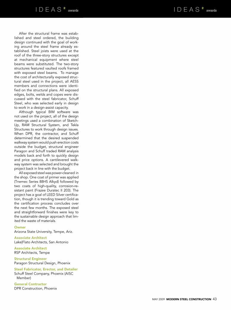
could not.”“The building at 185 Berry Street in San Fran-
cisco might look like any other building upon initial inspection. However, the struc-
ture houses a technically innovative application of seismic isolation to create mass damping in vertical building expansion.
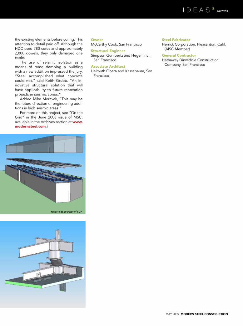
The goal was to expand an existing three-story, 216,000-sq.-ft building by 150,000 sq. ft in two new stories, with minimal disruption to the tenants. The existing building was 825 ft long (north to south) and 110 ft wide. To accommodate the long length of the building, two expansion joints were located approximately at the third points, dividing it into three separate structures. The addition is a continuous, approximately 800-ft-long structure, bridging these three independent structures below.
Engineer Simpson Gumpertz and Heger (SGH) constructed a 3D, non-linear model of the three wings in Ram Perform (now CSI Perform). The frame non-linearities were modeled using discrete plastic hinges with properties based on relevant tabulated values in FEma 356, modified using moment curvature analyses. The frame beam flexural capacities in the model were ob-tained using the composite action provided by the floor slab along with the existing prestress.
The non-linear time history analysis confirmed that the base isolated addition was not detrimen-tal to the existing structure. However, the peer review team wanted SGH to demonstrate that the building and the addition possessed the nec-essary toughness of a code compliant structure. To do so, SGH performed a reliability analysis us-ing data from incremental dynamic analyses. The results showed that the structure with the base isolated addition had a higher reliability than the base structure without the addition, clearly illus-trating the beneficial effect that isolation/mass damping would have on the overall performance of the building.
The project employs 87 seismic isolation bearings, all supplied by Dynamic Isolation Sys-tems (DIS). The design of the isolation system presented a significant challenge: isolating a relatively light superstructure while keeping the isolators stable at a displacement of +/– 45.5 in. (1.5 times the code required maximum displace-ment of +/– 30 in.). This required an isolation system consisting of 45-in.-diameter lead-rubber bearings and a new combined system of sliders in series with elastomeric bearings where the sliders provided +/– 30 in. of displacement and the additional +/– 15 in. of displacement was ac-
commodated in the 24-in.-diameter elastomeric bearing. Prototype test-ing demonstrated the bearings’ sta-bility.
SGH provided a grid of large structural steel members above and below the isolators to resist the mo-ments from the displaced isolators. To protect the relatively thin pre-stressed concrete roof slab, an inter-locking shear transfer system consist-ing of concrete pads connected to
the roof and steel shear lugs con-nected to the lower steel grid were used. The connection of the concrete pads to the existing roof employed 6-in.-diameter pipes cored into the slab as well as threaded rods epoxy grouted into the slab. Contractor Hathaway Dinwiddie Construction used ground-penetrating radar to lo-cate the post-tensioning cables and reinforcing steel, both in plan and elevation, and carefully laid out all of
Glenn Neville
may 2009 MODERN STEEL CONSTRUCTION
OwnermcCarthy Cook, San Francisco
Structural EngineerSimpson Gumpertz and Heger, Inc.,
San Francisco
associate architectHelmuth Obata and Kassabaum, San
the existing elements before coring. This attention to detail paid off. although the HDC used 780 cores and approximately 2,800 dowels, they only damaged one cable.
The use of seismic isolation as a means of mass damping a building with a new addition impressed the jury. “Steel accomplished what concrete could not,” said Keith Grubb. “an in-novative structural solution that will have applicability to future renovation projects in seismic zones.”
added mike moravek, “This may be the future direction of engineering addi-tions in high seismic areas.”
For more on this project, see “On the Grid” in the June 2008 issue of mSC, available in the archives section at www.modernsteel.com.)
MODERN STEEL CONSTRUCTION may 2009
awards
National award—$75M and greater CaLIfORNIa aCaDEMy Of SCIENCES—SaN fRaNCISCO
OwnerD.R. young associates, San Rafael, Calif.
architectRenzo Piano Building Workshop, Genova, Italy
associate architectStantec, San Francisco
Structural Engineerarup, San Francisco
Steel fabricator, Erector, and DetailerSmE Steel Contractors, West Jordan, Utah (aISC/NISD
member)
general ContractorWebcor Builders, San Francisco
innovative shapes—Christina Koch”
“
steel can create.
It’s a testament to the
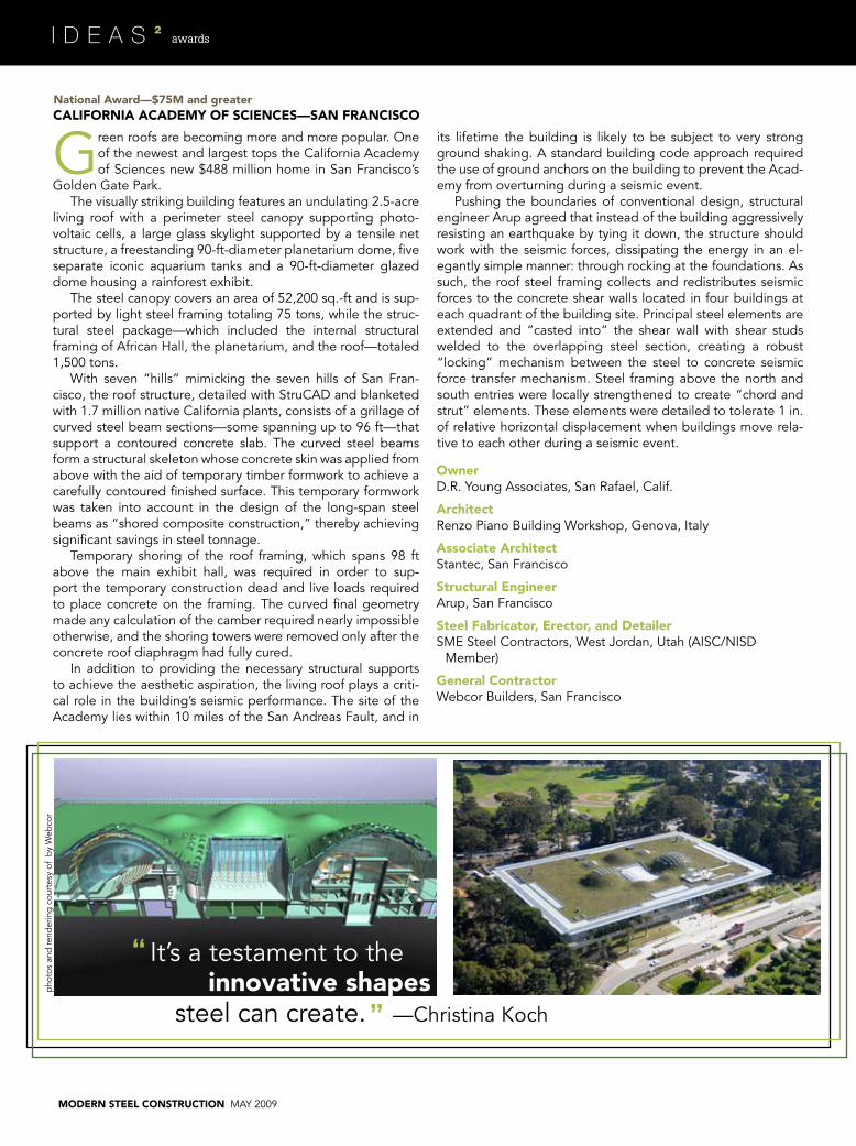
Green roofs are becoming more and more popular. One of the newest and largest tops the California academy of Sciences new $488 million home in San Francisco’s
Golden Gate Park.The visually striking building features an undulating 2.5-acre
living roof with a perimeter steel canopy supporting photo-voltaic cells, a large glass skylight supported by a tensile net structure, a freestanding 90-ft-diameter planetarium dome, five separate iconic aquarium tanks and a 90-ft-diameter glazed dome housing a rainforest exhibit.
The steel canopy covers an area of 52,200 sq.-ft and is sup-ported by light steel framing totaling 75 tons, while the struc-tural steel package—which included the internal structural framing of african Hall, the planetarium, and the roof—totaled 1,500 tons.
With seven “hills” mimicking the seven hills of San Fran-cisco, the roof structure, detailed with StruCaD and blanketed with 1.7 million native California plants, consists of a grillage of curved steel beam sections—some spanning up to 96 ft—that support a contoured concrete slab. The curved steel beams form a structural skeleton whose concrete skin was applied from above with the aid of temporary timber formwork to achieve a carefully contoured finished surface. This temporary formwork was taken into account in the design of the long-span steel beams as “shored composite construction,” thereby achieving significant savings in steel tonnage.
Temporary shoring of the roof framing, which spans 98 ft above the main exhibit hall, was required in order to sup-port the temporary construction dead and live loads required to place concrete on the framing. The curved final geometry made any calculation of the camber required nearly impossible otherwise, and the shoring towers were removed only after the concrete roof diaphragm had fully cured.
In addition to providing the necessary structural supports to achieve the aesthetic aspiration, the living roof plays a criti-cal role in the building’s seismic performance. The site of the academy lies within 10 miles of the San andreas Fault, and in
its lifetime the building is likely to be subject to very strong ground shaking. a standard building code approach required the use of ground anchors on the building to prevent the acad-emy from overturning during a seismic event.
Pushing the boundaries of conventional design, structural engineer arup agreed that instead of the building aggressively resisting an earthquake by tying it down, the structure should work with the seismic forces, dissipating the energy in an el-egantly simple manner: through rocking at the foundations. as such, the roof steel framing collects and redistributes seismic forces to the concrete shear walls located in four buildings at each quadrant of the building site. Principal steel elements are extended and “casted into” the shear wall with shear studs welded to the overlapping steel section, creating a robust “locking” mechanism between the steel to concrete seismic force transfer mechanism. Steel framing above the north and south entries were locally strengthened to create “chord and strut” elements. These elements were detailed to tolerate 1 in. of relative horizontal displacement when buildings move rela-tive to each other during a seismic event.
pho
tos
and
rend
erin
g c
ourt
esy
of b
y W
ebco
r
may 2009 MODERN STEEL CONSTRUCTION
awards
MODERN STEEL CONSTRUCTION may 2009
awards
National award—$75M and greater baNk Of OkLahOMa CENTER (bOk CENTER)—TULSa
Practically in the center of the country, the city of Tulsa, Okla. seems as good as any as a focal
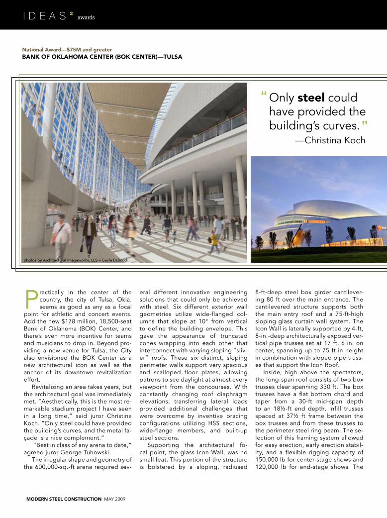
point for athletic and concert events. add the new $178 million, 18,500-seat Bank of Oklahoma (BOK) Center, and there’s even more incentive for teams and musicians to drop in. Beyond pro-viding a new venue for Tulsa, the City also envisioned the BOK Center as a new architectural icon as well as the anchor of its downtown revitalization effort.
Revitalizing an area takes years, but the architectural goal was immediately met. “aesthetically, this is the most re-markable stadium project I have seen in a long time,” said juror Christina Koch. “Only steel could have provided the building’s curves, and the metal fa-çade is a nice complement.”
“Best in class of any arena to date,” agreed juror George Tuhowski.
The irregular shape and geometry of the 600,000-sq.-ft arena required sev-
eral different innovative engineering solutions that could only be achieved with steel. Six different exterior wall geometries utilize wide-flanged col-umns that slope at 10° from vertical to define the building envelope. This gave the appearance of truncated cones wrapping into each other that interconnect with varying sloping “sliv-er” roofs. These six distinct, sloping perimeter walls support very spacious and scalloped floor plates, allowing patrons to see daylight at almost every viewpoint from the concourses. With constantly changing roof diaphragm elevations, transferring lateral loads provided additional challenges that were overcome by inventive bracing configurations utilizing HSS sections, wide-flange members, and built-up steel sections.
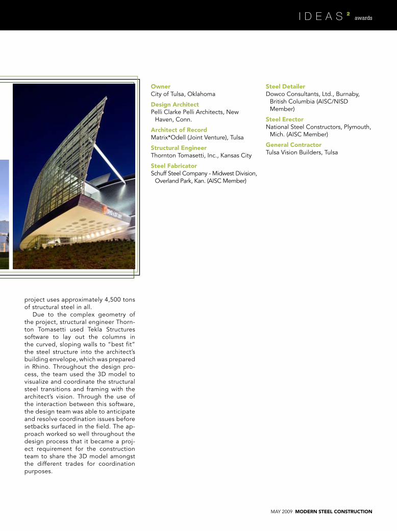
Supporting the architectural fo-cal point, the glass Icon Wall, was no small feat. This portion of the structure is bolstered by a sloping, radiused
8-ft-deep steel box girder cantilever-ing 80 ft over the main entrance. The cantilevered structure supports both the main entry roof and a 75-ft-high sloping glass curtain wall system. The Icon Wall is laterally supported by 4-ft, 8-in.-deep architecturally exposed ver-tical pipe trusses set at 17 ft, 6 in. on center, spanning up to 75 ft in height in combination with sloped pipe truss-es that support the Icon Roof.
Inside, high above the spectators, the long-span roof consists of two box trusses clear spanning 330 ft. The box trusses have a flat bottom chord and taper from a 30-ft mid-span depth to an 18½-ft end depth. Infill trusses spaced at 37½ ft frame between the box trusses and from these trusses to the perimeter steel ring beam. The se-lection of this framing system allowed for easy erection, early erection stabil-ity, and a flexible rigging capacity of 150,000 lb for center-stage shows and 120,000 lb for end-stage shows. The
photos by Architectural Imageworks, LLS – Gayle Babcock
may 2009 MODERN STEEL CONSTRUCTION
awards
project uses approximately 4,500 tons of structural steel in all.
Due to the complex geometry of the project, structural engineer Thorn-ton Tomasetti used Tekla Structures software to lay out the columns in the curved, sloping walls to “best fit” the steel structure into the architect’s building envelope, which was prepared in Rhino. Throughout the design pro-cess, the team used the 3D model to visualize and coordinate the structural steel transitions and framing with the architect’s vision. Through the use of the interaction between this software, the design team was able to anticipate and resolve coordination issues before setbacks surfaced in the field. The ap-proach worked so well throughout the design process that it became a proj-ect requirement for the construction team to share the 3D model amongst the different trades for coordination purposes.
OwnerCity of Tulsa, Oklahoma
Design architectPelli Clarke Pelli architects, New
Haven, Conn.
architect of Record matrix*Odell (Joint Venture), Tulsa
Structural EngineerThornton Tomasetti, Inc., Kansas City
Steel fabricatorSchuff Steel Company - midwest Division,
Structural EngineerLund and Everton, LLC, Vashon, Wash.
Steel fabricatorFought and Company, Inc., Tigard, Ore. (aISC member)
DetailerSteel Systems Engineering, Inc., Sherman Oaks, Calif.
(aISC/NISD member)
general ContractorSellen Construction Company, Seattle
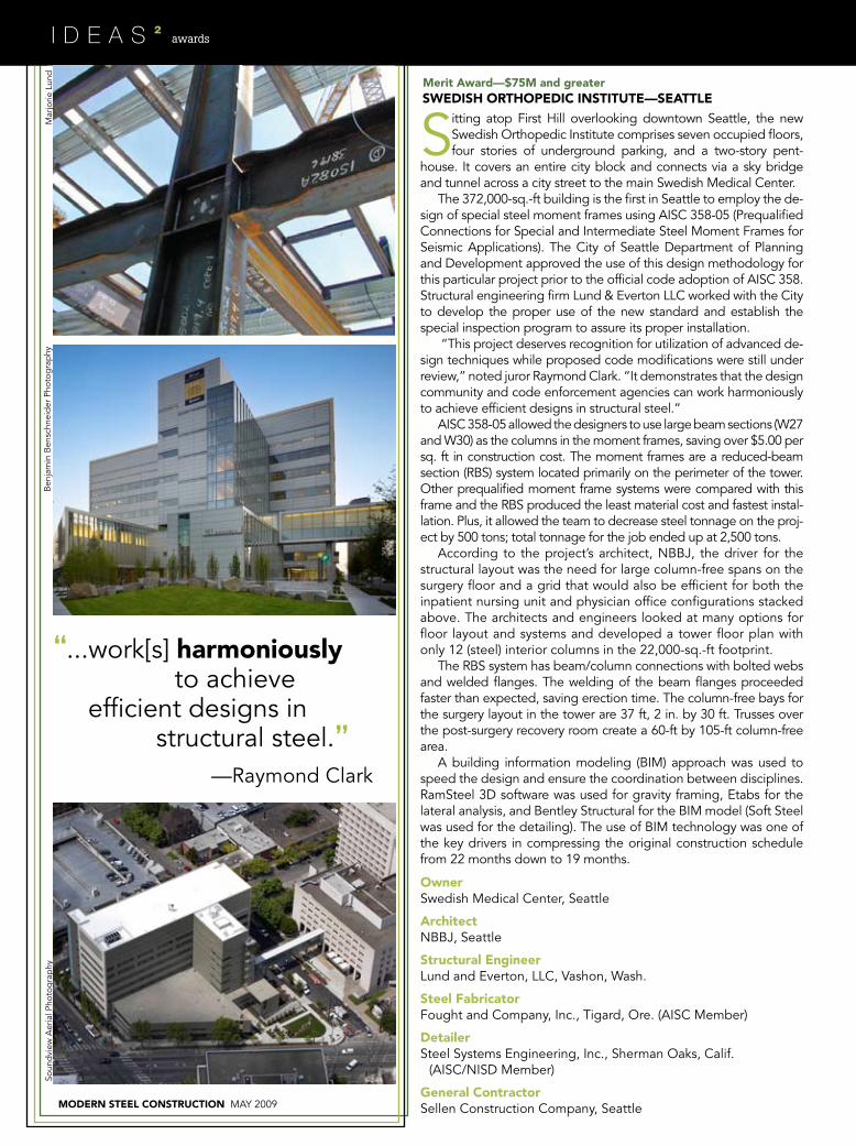
Merit award—$75M and greater SwEDISh ORThOpEDIC INSTITUTE—SEaTTLE
—Raymond Clark
”
“...work[s] harmoniously
efficient designs instructural steel.
to achieve
Sitting atop First Hill overlooking downtown Seattle, the new Swedish Orthopedic Institute comprises seven occupied floors, four stories of underground parking, and a two-story pent-
house. It covers an entire city block and connects via a sky bridge and tunnel across a city street to the main Swedish medical Center.
The 372,000-sq.-ft building is the first in Seattle to employ the de-sign of special steel moment frames using aISC 358-05 (Prequalified Connections for Special and Intermediate Steel moment Frames for Seismic applications). The City of Seattle Department of Planning and Development approved the use of this design methodology for this particular project prior to the official code adoption of aISC 358. Structural engineering firm Lund & Everton LLC worked with the City to develop the proper use of the new standard and establish the special inspection program to assure its proper installation.
“This project deserves recognition for utilization of advanced de-sign techniques while proposed code modifications were still under review,” noted juror Raymond Clark. “It demonstrates that the design community and code enforcement agencies can work harmoniously to achieve efficient designs in structural steel.”
aISC 358-05 allowed the designers to use large beam sections (W27 and W30) as the columns in the moment frames, saving over $5.00 per sq. ft in construction cost. The moment frames are a reduced-beam section (RBS) system located primarily on the perimeter of the tower. Other prequalified moment frame systems were compared with this frame and the RBS produced the least material cost and fastest instal-lation. Plus, it allowed the team to decrease steel tonnage on the proj-ect by 500 tons; total tonnage for the job ended up at 2,500 tons.
according to the project’s architect, NBBJ, the driver for the structural layout was the need for large column-free spans on the surgery floor and a grid that would also be efficient for both the inpatient nursing unit and physician office configurations stacked above. The architects and engineers looked at many options for floor layout and systems and developed a tower floor plan with only 12 (steel) interior columns in the 22,000-sq.-ft footprint.
The RBS system has beam/column connections with bolted webs and welded flanges. The welding of the beam flanges proceeded faster than expected, saving erection time. The column-free bays for the surgery layout in the tower are 37 ft, 2 in. by 30 ft. Trusses over the post-surgery recovery room create a 60-ft by 105-ft column-free area.
a building information modeling (BIm) approach was used to speed the design and ensure the coordination between disciplines. RamSteel 3D software was used for gravity framing, Etabs for the lateral analysis, and Bentley Structural for the BIm model (Soft Steel was used for the detailing). The use of BIm technology was one of the key drivers in compressing the original construction schedule from 22 months down to 19 months.
Soun
dvi
ew a
eria
l Pho
tog
rap
hym
arjo
rie L
und
Ben
jam
in B
ensc
hnei
der
Pho
tog
rap
hy
may 2009 MODERN STEEL CONSTRUCTION
awards
Merit award—$75M and greater UNIvERSITy Of ILLINOIS MEMORIaL STaDIUM—ChaMpaIgN, IL
OwnerUniversity of Illinois, Champaign
architect and Structural EngineerHNTB architecture, Kansas City
associate architectIsaksen Glerum Wachter, LLC, Urbana, Ill.
Steel fabricator and DetailerBlattner Steel, Cape Girardeau, mo.
(aISC member)
general ContractorHunt Construction, Indianapolis
Steel design, sustainability,
—mark Carter
”
“
with a beautiful result.and constructability win again;
Built in 1923 in a classical revival architectural style, the University of Illinois memorial Stadium plays home to the Fighting Illini football team. after more than 80 years of
use, though, the stadium was in need of upgrades. an expan-sion plan, completed in time for the 2008 season, brought the historic landmark into the 21st century, involving the addition of 49 luxury suites, premium clubs, a north end-zone seating bowl, and a training facility, enlarging concourses, and replac-ing restrooms and concessions.
In many stadium expansions, the suites and additional levels are added adjacent to and outside an existing seating bowl. However, this addition was constructed inside and above the existing facility.
The primary challenges were related to construction phas-ing, sequencing, logistics, and tight working quarters. The project plan called for the main existing transfer trusses in the interior of the west stadium to be partially demolished to re-ceive the new structure. To prevent damage to the historic fa-çade and colonnades, the existing structure had to be shored, jacked, reinforced, selectively demolished, re-jacked, and sup-ported prior to the completion of the new structure, all while minimizing any movement. The historical masonry façade and other brittle elements were continuously monitored during the process to verify they were not damaged.
Slabs on composite metal deck, supported by composite steel beams, and steel transfer trusses were designed to sup-port the new facility. Using steel allowed the new system to integrate with the old, transfer between two different structural grids, and meet the fast schedule demands, as well as provided the flexibility to adjust connections and configurations in the
field when reacting to uncovered surprises and tolerances in the existing structure.
The material properties of the structure’s 1920s-era steel are far different from that of today’s steel. as such, material testing was conducted on the existing steel to establish the new weld-ing and bolting provisions necessary. Testing revealed welding was possible, but drilling and bolting to the existing riveted structure was used for all connections with high loads.
“In an era when so many stadiums are torn down to build new, it’s nice to see a stadium utilizing steel for a renovation that respects its historical significance,” said juror Christina Koch.
Column loads from the radial structural grid between the upper story suites were transferred to the smaller, orthogo-nal existing grid supporting the lower bleachers and historic façade. as a result, no single column continued directly from the roof to the foundation. Transfer girders and trusses, both new and existing, were designed to provide a load path for the columns.
The new design required the existing trusses to be cut in half while they were still supporting the upper half of the build-ing. Where existing trusses were cut, an 8-ft-deep perpendicu-lar transfer truss constructed of 12-in. wide-flange sections was erected to support the existing trusses. In addition, a second transition from the 45-ft column spacing of the existing stadium to a 30-ft radial column spacing of the upper levels occurred two levels further above using transfer girders. Total steel used was approximately 3,300 tons.
For more on this project, see “Big Draw” the Febru-ary 2009 issue of mSC, available in the archives section at www.modernsteel.com.