Page 1
Innovative Proposal for Multifunctional
SUV Rear Seat A Major Qualifying Project Report
submitted to the Faculty of
WORCESTER POLYTECHNIC INSTITUTE
in partial fulfillment of the requirements for the
Degree of Bachelor of Science
By
_______________ ________________ Edgar J Buenrostro Alberto A Mateo
In partnership with Shanghai University
and Partners
Xianliang Chi and Benjian Huang
Date: April 25, 2013
Approved By:
________________________________ Professor Yiming (Kevin) Rong, Advisor, WPI, ME
Page 2
ii
ABSTRACT
The principal objective of this paper is to exhibit the most feasible method to
design a multifunctional SUV rear seat successfully. The intent of this project
is to provide a detailed explanation of the steps taken to design the rear seat.
Thus, it provides the essentials of the SUV seat market as well as samples of
the designs from the group, in which it is possible to appreciate the common
risks and mistakes a designer is susceptible to while implementing an idea. In
addition, it includes an explanation of the methodology utilized by the group.
Page 3
iii
Acknowledgement
We would like to thank Kevin Rong, Professor, Mechanical Engineering
Department, Richard Sisson, Professor, Worcester Polytechnic Institute,
Zhang Xi, Professor, Guoshuai, Professor, Xianliang Chi, Student, Benjian
Huang, Student, Shanghai University, Zhengxian Tang, Industrial Mentor,
Marius De Coquereaumont, Intern, Johnson Controls for their guidance and
contributions throughout the course of this project and to this project.
Page 4
iv
Table of Contents Abstract……….…………………………………………………………………………………..ii
Acknowledgement…………………………………………….…………………............…........iii
Table of Figures ......................................................................................................................... …iv
Chapter 1. Introduction .......................................................................................................................... 1
1.1 Project Description .............................................................................................................................. 2
Chapter 2. Background ........................................................................................................................... 4
2.1 Company Background ......................................................................................................................... 4
2.2 SUV Background .................................................................................................................................. 6
2.2.1 Types of SUVs ............................................................................................................................... 7
2.2.2 Rear Seat Folding Ways ................................................................................................................ 8
Chapter 3. Objective ............................................................................................................................. 14
Chapter 4. Methodology ....................................................................................................................... 15
4.1 Pre Qualifying Project ....................................................................................................................... 17
4.1.1 Benchmark Study ....................................................................................................................... 18
Chapter 5. Results ................................................................................................................................. 23
5.1 Mechanism Ideas .............................................................................................................................. 23
5.2 Final Design ....................................................................................................................................... 25
5.2.1 Iterations .................................................................................................................................... 27
5.3.2 FEA ............................................................................................................................................. 29
5.3.3 Cost Analysis .............................................................................................................................. 31
Chapter 6. Conclusion and Recommendations ..................................................................................... 33
Chapter 7. References .......................................................................................................................... 34
Chapter 8. Appendix A .......................................................................................................................... 35
Page 5
v
8.1 Chart Score Explanation ................................................................................................................ 35
Chapter 9. Appendix B .......................................................................................................................... 36
9.1Mechanism Concepts ..................................................................................................................... 36
9.2 Design Iterations ........................................................................................................................... 37
Chapter 10. Appendix C .......................................................................................................................... 39
10.1 Seat Basic Specs .............................................................................................................................. 39
Chapter 11. Appendix D .......................................................................................................................... 40
11.1 Project Gant Chart .......................................................................................................................... 40
Page 6
vi
Table of Figures
Figure 2.1 Full Size SUV Interior/Exterior ...................................................................................................... 8
Figure 2.2 Fold-Flat Folding ........................................................................................................................... 9
Figure 2.3 Vertical Folding Mechanism ....................................................................................................... 10
Figure 2.4 Fold and Hang to the Side .......................................................................................................... 10
Figure 2.5 Moving (Sliding) Method ........................................................................................................... 11
Figure 2.6 Moving Option for the Disabled…………………………………………………………………………………………….12
Figure 2.7 Luxury Moving Option ................................................................................................................ 12
Figure 2.8 Disassembling Option ................................................................................................................ 13
Figure 2.9 Rotating Option .......................................................................................................................... 13
Figure 4.1. PQP Flowchart .......................................................................................................................... 16
Figure 4.2. MQP Flowchart ........................................................................................................................ 17
Figure 4.3 Head Retrain Adjustment Figure 4.4 Backrest Adjustment ................................................... 19
Figure 4.5 SUV Evolution ............................................................................................................................. 20
Figure 4.6 SUV Models Provided ................................................................................................................. 21
Figure 5.1 Design Concept Finalists ............................................................................................................ 24
Figure 5.2 Sample Brainstorm Mechanism Concept ................................................................................... 25
Figure 5.3 Box Concept Design ................................................................................................................... 25
Figure 5.4 Final Design Concept .................................................................................................................. 26
Figure 5.5 Final Design Iteration 1 .............................................................................................................. 27
Figure 5.6 Final Design Iteration 2 (Chosen Design) ................................................................................... 28
Figure 5.7 Pugh Analysis ............................................................................................................................. 29
Figure 5.8 Our ANSYS Tests ......................................................................................................................... 30
Figure 5.9 ANSYS Results From Online Study.............................................................................................. 30
Figure 5.10 Belt Selection Charts ................................................................................................................ 31
Figure 5.11 Cost Analysis Chart ................................................................................................................... 32
Figure 9.1 Mechanism Concepts ................................................................................................................. 36
Figure 9.2 Box Iteration 1 ............................................................................................................................ 37
Figure 9.3 Box Iteration 2 ............................................................................................................................ 37
Figure 9.4 Box Concept Comparison ........................................................................................................... 38
Figure 10.1 Seat General Specscepts .......................................................................................................... 39
Figure 11.1 Project Gant Chart ................................................................................................................... 40
Page 7
1
Chapter 1. Introduction At the present time it is crucial for all types of businesses to exist in a competitive
environment. Competiveness functions as a constant motivation given the fact that everyone
requires to deliver the best product in order to obtain a good profit. However, delivering the best
product involves countless aspects depending on the specific business type. Johnson Controls as
an instance, being the main car seat manufacturer globally, is obligated to be innovative and
reliable.
In order to become competitive in the coming years Johnson Controls necessitated having
an innovative solution for the SUV seating. Therefore, the company had assigned the team to
support this task as a senior design project. Johnson Controls’ main idea was to develop an
ingenious functionality without compromising cost and visuals. With this accomplishment the
company planned to be able to widen its knowledge and services to ensure the customer the best
quality output.
The role of the team during this project was to work closely with Johnson Controls to
successfully achieve the goals set. Design an innovative mechanism for the movable and foldable
functionality of the rear seat of an SUV. For this task the team was assigned to an advisor from
Johnson Controls in order to be able follow all company standards.
Students from WPI and SHU were required to work together for seven weeks in order to
complete the proposal in a timely manner. Overall this project was substantial because it was not
just a grade for a class; Johnson Controls was inverting its time and trusting its outstanding position
in the vehicle industry on the team. Therefore as a group the students put all their efforts to deliver
Page 8
2
a good product just like Johnson Controls has always dependably been doing in order to be one of
the most competitive car seating manufacturers globally.
1.1 Project Description
With the purpose to provide a clear understanding of the project, Johnson Controls sent the
group a concise presentation with the project description. As it was entitled, “Innovative Proposal
for the Multifunctional Rear Seat for SUV”, this brief presentation clarified the main objective; to
develop a new advanced and appealing functionality for the rear seat of an SUV.
Johnson Controls interest on the SUV market was aroused by the Global Market Research
Company JD-Power forecast. The SUV market is expected to increase in China in the following
five years. Additionally, OEM (Original Equipment Manufacturer), incorporate components into
new products with its own brand name, had demonstrated its attention on the developments of
SUV during last years. Especially concerning the combo luggage space, which would require
versatile movable and foldable rear seats.
Johnson Controls in China had never worked with SUVs therefore a feasible and innovative
solution for the rear seat of an SUV was required in order to become competitive in this detail
market in the following years. The initial goals presented for the group were the followings:
- Make a benchmark for the SUV rear seat trend
- Create concepts for the rear seats new functions
- Finish 3D data and movement evaluation
- Produce a Prototype
Page 9
3
These goals would provide a good product to show the customers and help the first phase
to quote the new SUV rear seat functions. However, based on the duration of the project and the
numerous functionalities that could be implemented to the SUV rear seat, the goals were slightly
changed. As it will be explained in Chapter 4, Johnson Controls in accordance with the group
decided to focus in a single functionality based on the customers’ needs.
Page 10
4
Chapter 2. Background This section of the report contains the background information of the sponsor company and
the SUV. A brief investigation about the history of Johnson Controls was made in order to learn
more about the company the group was going to work with. Additionally, the evolution of the SUV
was researched to target the main improvements over the years. Different types of SUVs were
also traced to be aware of the necessary space the group needed to take under consideration.
2.1 Company Background
The founder of Johnson Controls was Professor Warren S. Johnson. It was not until he
received a patent for the first electric room thermostat, that he had the opportunity to begin building
the control industry. The name Johnson Controls was established in 1974, after a group of investors
integrated the Johnson Electronic Service Company in 1885. The purpose of this adopted company
was to manufacture, install and service automatic regulation system for buildings. From 1885 until
his death in 1911, the professor tried to expand the company by developing new areas such as
steam and gas powered automobiles and electric storage batteries. However, at the time of his
death Johnson Controls decided to only focus on the business of temperature control for
nonresidential buildings.
During the 1950’s, Johnson Controls was developing new technologies to better serve their
clients managing the buildings. For instance, Johnson Controls invented the Pneumatic Control
Center, which monitored all temperature devices installed in the building from a single point. This
invention resulted to be extremely helpful since building would have a large amount of devices
that control the temperature installed all around such as dampers, valves and thermostats.
Page 11
5
The JC80, another technology created by Johnson Controls was introduced in 1972. This
minicomputer was also developed to control the buildings. As years passed, the technology at
Johnson Controls continued to grow, introducing a digital version of the JC80, the JC85 in the
1980’s. This new version allowed a more accurate and faster control of building systems.
Throughout the 1990’s, the company led the way to allow different devices from other
manufacturers to share data. Metasys Facilities Management System is its most recent control
system.
Another business adopted by Johnson Controls in the 1980’s in was the systems to manage
commercial buildings. In order to accomplish this, the company increased its services to
incorporate electrical and mechanical tools. The Integrated Facilities Management (IFM) was then
introduced to provide to the clients a single center of maintenance and operations for all building
functions and systems. In addition the IFM was developed to guarantee a continued dependability
and effectiveness to the structure and configuration of the buildings.
As previously mentioned, before his death, Professor Warren S. Johnson had an interest on
expanding the company by adding new areas of study such as automobile batteries. In response
for his concern, currently Johnson Controls is the main manufacturer of private-label lead-acid
automotive batteries in North America. Some of the brands that the company manufactures
automotive batteries for are Heliar, LTH, Optima and Varta, in addition to lots of private brands.
Furthermore, Johnson Controls also manufactures batteries for telecommunication applications
and emergency power back up. The company continues to develop new technologies in automotive
batteries and is expanding its leadership to all America and Asia.
Page 12
6
In 1985, Johnson Controls acquired Michigan-based Hover Universal, Inc., which started
business in the 1960’s manufacturing car seats components such as frames, cushions and tracks.
After this acquisition Johnson Controls began its business in the automotive seating along with
plastics machinery. Now, thanks to its outstanding accomplishments in the car seating industry,
the company has become the main manufacturer in five continents. During the last decade, the
company has been trying to improve the car seating industry by the development of research,
engineering, design and testing capabilities in order to provide both costumers and cars
manufacturers systems with enhanced technology, comfort and safety.
2.2 SUV Background
A sport utility vehicle (SUV) is a vehicle that provides the passenger space of a minivan,
the towing capacity of a pick-up truck and usually four-wheel drive. The term SUV varies in
different countries and is mostly applied in North America. In some other parts of the world
different terms are utilized such as off road vehicle, four-wheel drive (4WD) or four-by-four (4x4).
The history of the SUV began with the “depot hack”, which was a vehicle that transported people
and their luggage from train stations. The Suburban (longest SUV) and the station wagon were
created based on the depot hack. However, the terms “suburban” and “carryall” were mainly used
in reference to early SUV models in the 1920’s. “Carryall” was used since its main purpose was
to be practical and carry all, whether it was cargo or people.
One of the main purposes of a SUV is its off-road capabilities. This feature is often required
in places with limited paved roads such as northern United States, South America, Alaska, Canada
and Middle East. These places need a vehicle with all-terrain handling, large storage space and
range. In addition, some SUVs provide a minimum of hydraulic and electric systems such as the
Page 13
7
Toyota Land Cruiser and the Land Rover, which is helpful in the unfortunate situation of scarcity
of spare parts. Additionally, in order to attract the greatest possible audience, modern SUV models
provide a lower ground clearance and suspension especially intended for paved roads.
Throughout the years SUVs have become popular due to their large storage space, higher
ride space, larger passenger capacity, improved safety and off-road capabilities. Full size SUVs
usually offer three row seating, which is very convenient to transport up to seven people replacing
the minivan and station wagons. Furthermore, some modern SUVs have an improved towing
capability which can haul boats and trailers. In terms of security, SUVs are also designed to drive
in hazardous conditions such as on gravel roads and snow. Their outstanding performance in places
where drivers often come across detours, high water, mud and rough roads has placed the SUV in
a competitive spot when it comes to efficient driving. Overall it isn’t hard to predict the SUV’s
increasing popularity over conventional cars in the following years.
2.2.1 Types of SUVs
SUV’s designs have changed throughout the years as the consumer demands have required
different functionalities. SUVs are historically known for its high ground clearance and mid-size
passenger space. However, unlike today where SUV’s are more of a family oriented vehicle, early
SUV’s were designed with two doors and some with removable tops. Current SUV’s provide much
more functionalities that bring out the concepts of comfort and safety to a whole new level. All of
which can be very attractive to a family that needs all the versatility.
SUV’s designs vary on sizes and are classified in Compact SUV, Midsize SUV and Full
Size SUV. The compact SUV refers to the smallest SUV on the market since they are generally
built with less passenger and cargo space. Midsize SUV on the other hand are not commonly
Page 14
8
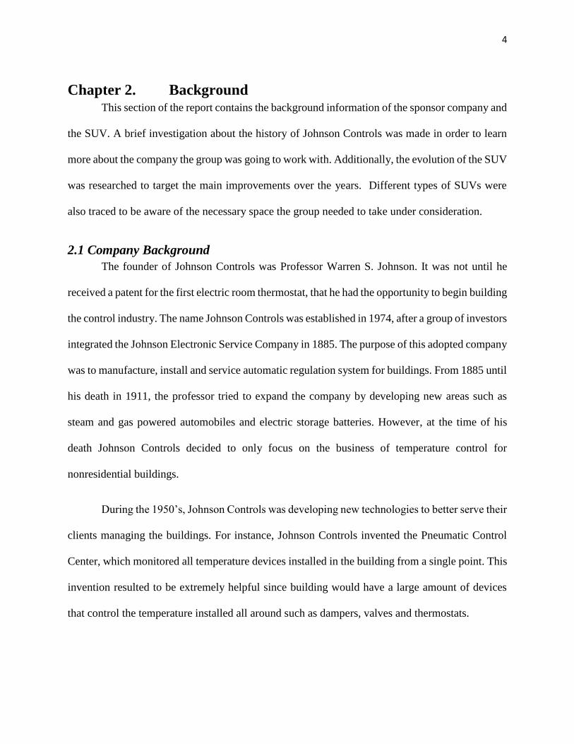
known outside North America where it is usually compared and confused with a full size SUV.
However, full size SUV’s provides the most cargo and passenger space with usually a third row
seating space. As shown in Figure 2.1 below, the mid-size and full-size SUV provide the most
space in terms of storage and seat capacity.
Figure 2.1 Full Size SUV Interior/Exterior
However, full-size are not very common outside the United States, as United States version
of the mid-size is usually considered full-size. Also, due to the nature of the Chinese market the
small or compact sized SUV are the most attractive of all the different sizes. It is for this reason
that our three benchmark SUV’s, the Tiguan (SVW), CRV (HONDA), and Haval (Great Wall), all
fall under the compact-size category for SUV’s.
2.2.2 Rear Seat Folding Ways
One of the main functions of an SUV is the capacity to rearrange the rear seats to provide
more cargo space. Due to the demand in the market for compact SUV’s one important feature is
the ability to provide better storage when the cargo space is needed over seat capacity. This is
important, since compact SUV’s do not have the same ability as the full-size SUV’s, which provide
large cargo space, and great seat capacity. Due to the limitations of space and variations of the
different models, manufacturers must implement innovative ideas to meet the needs of the market.
They must not only adapt to the shape of the model, but they must provide the best possible storage
space rearrangement, while not compromising aesthetics.
Page 15
9
There exists several ways to fold and reorganize these seats and it varies based on the
manufacturers and models. Some of the main types are the folding, moving, adjusting,
disassembling, and rotating. The most popular out of these to fold the rear seats of an SUV are the
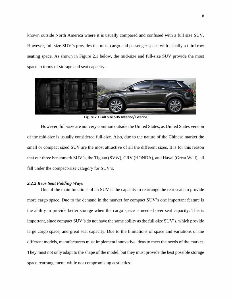
“folding-flat” and the “vertical-folding”. The folding-flat option provides an intuitive mechanism
and a clean look as shown in Figure 2.2. This method usually provides the best look and largest
horizontal cargo space. However, one downside to this mechanism is that it does not provide the
greatest vertical space. The mechanisms usually tend to be either manually operated, or automated
by a press of a button. Generally the manufacturers aim to achieve the folding operation in the
least amount of steps, or the lowest number of operations. This is due to the fact that the lower
amount operations are a more user-friendly alternative, and could at times also mean a cheaper
alternative. However, the automated option is usually for the more expensive or luxurious models,
as this is a more expensive option.
Figure 2.2 Fold-Flat Folding
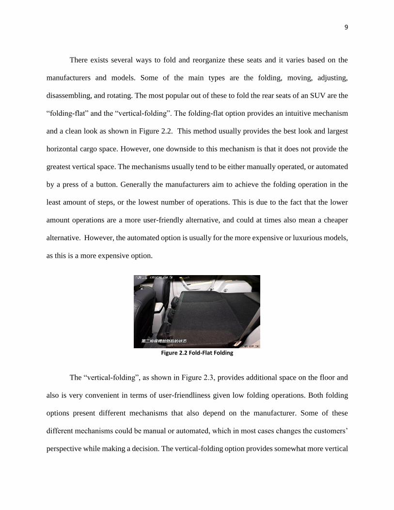
The “vertical-folding”, as shown in Figure 2.3, provides additional space on the floor and
also is very convenient in terms of user-friendliness given low folding operations. Both folding
options present different mechanisms that also depend on the manufacturer. Some of these
different mechanisms could be manual or automated, which in most cases changes the customers’
perspective while making a decision. The vertical-folding option provides somewhat more vertical
Page 16
10
storage space as it frees the space needed to hide the seat. However, the downside is that this option
is not as neat folding as the fold-flat option. Also, this option provides less horizontal storage
space.
Figure 2.3 Vertical Folding Mechanism
A variation of the vertical-folding mechanism exists as the fold and hang as shown in
Figure 2.4.
Figure 2.4 Fold and Hang to the Side
This option usually involves folding down of the backrest onto the cushion and then taking
the entire folded seat to the side and hangs. This mechanism is usually used as an automated option.
While this option provides great space on the center of the storage space, it does not provide as
clean of a look as the fold-flat option or the regular vertical folding. Also, this method would
usually be used on large-size SUV’s as this option would block the side doors.
Page 17
11
Figure 2.5 Moving (Sliding) Method
A variation in some vehicles is the moving option as shown in figure 2.5. When this option
is used the cushion of the seat does not move of the floor, but rather it slides forward and to the
sides. While the seat is able to slide forward to the front seat, this method does not provide a clean
look to the vehicle, as is has the most bulk out of the methods we have talked about so far.
However, a great benefit to this method is the low cost involved in this option, which is perhaps
the main reason it is used in some vehicles models. A slight advantage in this mechanism is the
ability to adjust for leg space as needed by the passenger, an option that is not normally available
in these models. At the same time this mechanism also provides slight increase in storage space
while not having to reduce the seating capacity. A feature that can come in very handy in certain
situations.
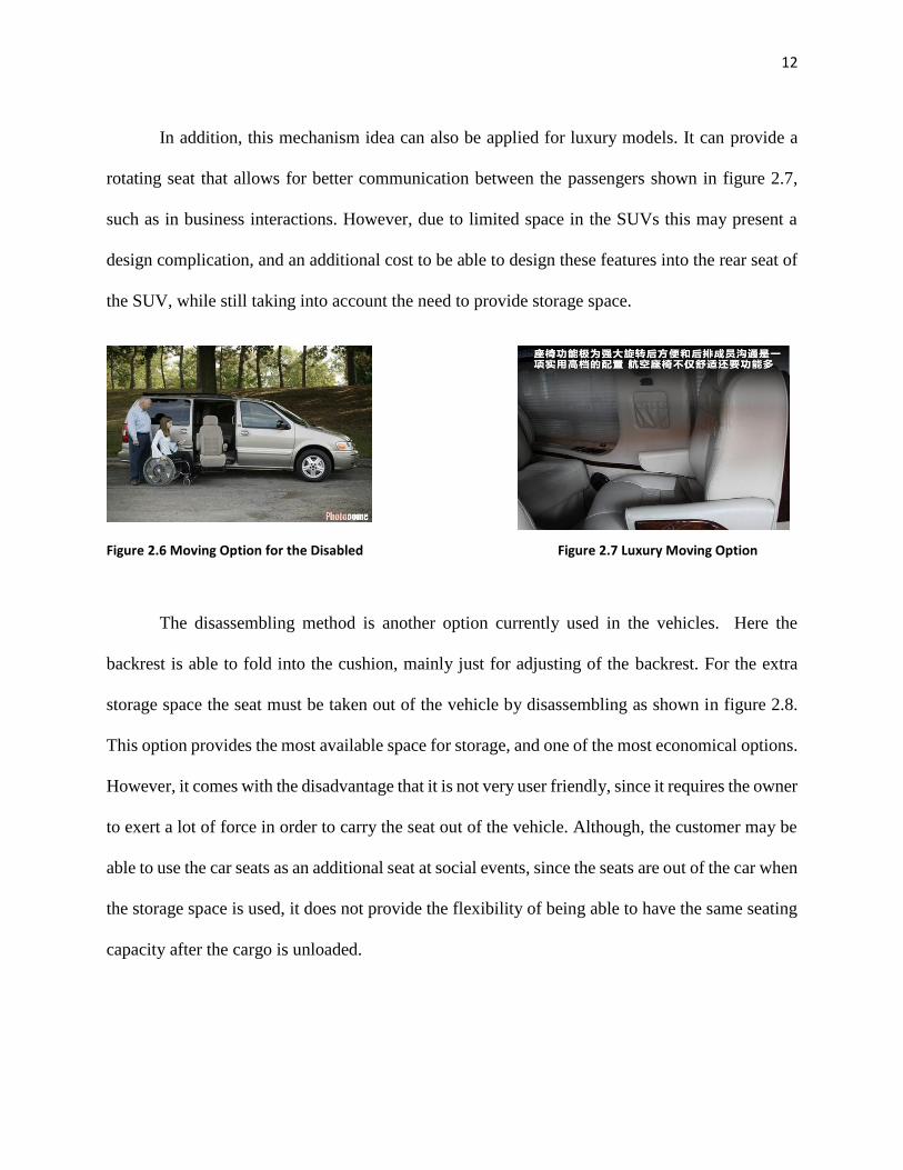
Also, another application of the idea of the mechanism is the integration of a movable rear
seat that could add convenience for disabled passengers by placing the seat out of the door. This
feature as shown in figure 2.6, can make it easier for these passengers to go into the car.
Page 18
12
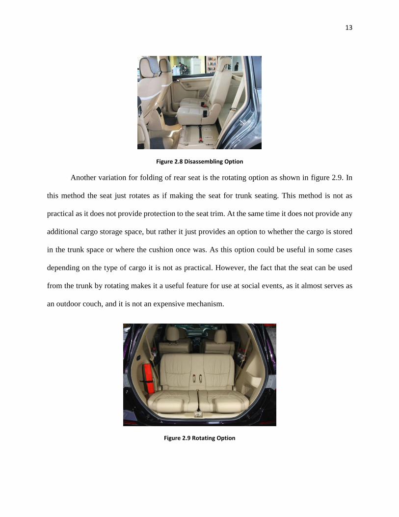
In addition, this mechanism idea can also be applied for luxury models. It can provide a
rotating seat that allows for better communication between the passengers shown in figure 2.7,
such as in business interactions. However, due to limited space in the SUVs this may present a
design complication, and an additional cost to be able to design these features into the rear seat of
the SUV, while still taking into account the need to provide storage space.
Figure 2.6 Moving Option for the Disabled Figure 2.7 Luxury Moving Option
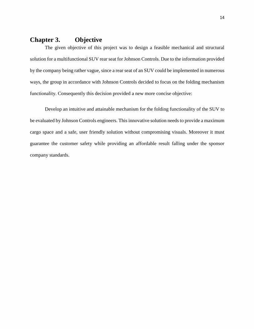
The disassembling method is another option currently used in the vehicles. Here the
backrest is able to fold into the cushion, mainly just for adjusting of the backrest. For the extra
storage space the seat must be taken out of the vehicle by disassembling as shown in figure 2.8.
This option provides the most available space for storage, and one of the most economical options.
However, it comes with the disadvantage that it is not very user friendly, since it requires the owner
to exert a lot of force in order to carry the seat out of the vehicle. Although, the customer may be
able to use the car seats as an additional seat at social events, since the seats are out of the car when
the storage space is used, it does not provide the flexibility of being able to have the same seating
capacity after the cargo is unloaded.
Page 19
13
Figure 2.8 Disassembling Option
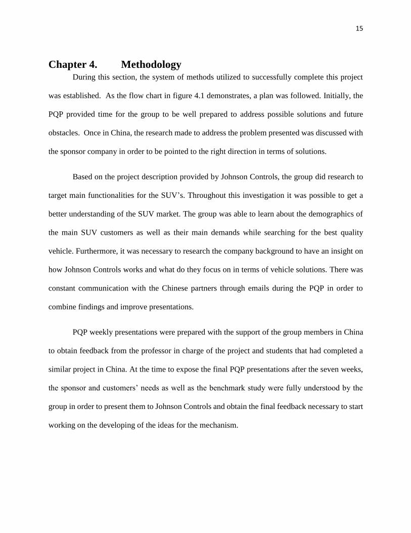
Another variation for folding of rear seat is the rotating option as shown in figure 2.9. In
this method the seat just rotates as if making the seat for trunk seating. This method is not as
practical as it does not provide protection to the seat trim. At the same time it does not provide any
additional cargo storage space, but rather it just provides an option to whether the cargo is stored
in the trunk space or where the cushion once was. As this option could be useful in some cases
depending on the type of cargo it is not as practical. However, the fact that the seat can be used
from the trunk by rotating makes it a useful feature for use at social events, as it almost serves as
an outdoor couch, and it is not an expensive mechanism.
Figure 2.9 Rotating Option
Page 20
14
Chapter 3. Objective The given objective of this project was to design a feasible mechanical and structural
solution for a multifunctional SUV rear seat for Johnson Controls. Due to the information provided
by the company being rather vague, since a rear seat of an SUV could be implemented in numerous
ways, the group in accordance with Johnson Controls decided to focus on the folding mechanism
functionality. Consequently this decision provided a new more concise objective:
Develop an intuitive and attainable mechanism for the folding functionality of the SUV to
be evaluated by Johnson Controls engineers. This innovative solution needs to provide a maximum
cargo space and a safe, user friendly solution without compromising visuals. Moreover it must
guarantee the customer safety while providing an affordable result falling under the sponsor
company standards.
Page 21
15
Chapter 4. Methodology During this section, the system of methods utilized to successfully complete this project
was established. As the flow chart in figure 4.1 demonstrates, a plan was followed. Initially, the
PQP provided time for the group to be well prepared to address possible solutions and future
obstacles. Once in China, the research made to address the problem presented was discussed with
the sponsor company in order to be pointed to the right direction in terms of solutions.
Based on the project description provided by Johnson Controls, the group did research to
target main functionalities for the SUV’s. Throughout this investigation it was possible to get a
better understanding of the SUV market. The group was able to learn about the demographics of
the main SUV customers as well as their main demands while searching for the best quality
vehicle. Furthermore, it was necessary to research the company background to have an insight on
how Johnson Controls works and what do they focus on in terms of vehicle solutions. There was
constant communication with the Chinese partners through emails during the PQP in order to
combine findings and improve presentations.
PQP weekly presentations were prepared with the support of the group members in China
to obtain feedback from the professor in charge of the project and students that had completed a
similar project in China. At the time to expose the final PQP presentations after the seven weeks,
the sponsor and customers’ needs as well as the benchmark study were fully understood by the
group in order to present them to Johnson Controls and obtain the final feedback necessary to start
working on the developing of the ideas for the mechanism.
Page 22
16
Figure 4.1. PQP Flowchart
Once in Shanghai China, multiple visits were made to Johnson Controls to meet the people
running the project in order to work closely with them and to get a better understanding on what
is expected from the group. Moreover it was possible to get a closer look at the company’s
manufacturing processes by the provided tours which were very helpful while coming up with
innovative ideas for the mechanism.
An intern working for Johnson Controls was in charge of the project and to work closely
with the group. After discussing all different rear seat functionalities researched during the PQP
and based on the customers’ needs it was decided to work with the folding functionality of the
SUV. This functionality was chosen because it targeted the main SUV characteristics demanded
such as the storage space and aesthetics.
Once the specific SUV functionality for the rear seat was selected, the group and the intern
from the sponsor company decided to brainstorm possible folding mechanisms in order to begin
PQPProject Description
by Sponsor Company Analysis
Online Discussion with partners from
China
Benchmark Study and Company Background
Research exchange with foreign
partners
Final PQP Presentation
Page 23
17
the technical work and choose the feasible solutions from all the ideas generated, some which can
be found in appendix A. Designs were then created for all the mechanisms that proved to be
innovative after several meetings and discussions with Johnson Controls engineers.
Lastly, comparisons were made to all final designs to assess advantages and disadvantages.
However, in order to better appreciate the capability of all this designs, CAD models were created
to present simulations and be able to apply a structural test.
Figure 4.2 illustrates all the process described in this section for a better understanding.
Figure 4.2. MQP Flowchart
4.1 Pre Qualifying Project
During the seven weeks of the PQP, both the students from WPI and SHU prepared a
presentation to introduce the project and the main topics such as project objectives and benchmark
MQP
Chinese Partners Introduction
Initial Presentation Rehersal for
Sponsor Company
Sponsor Company Visit
Goals and Objectives Update based on feedback
acquired
Mechanisms Brainstorm with
Sponsor Company Advisor
Comparison of designs chosed by Sponsor Company
Mechanical and Strucutural analysis
to Final Designs
Final Presentation
Page 24
18
studies. The PQP’s principal objective was to visualize what was expected to be completed while
in China in order to accomplish all objectives successfully on time.
4.1.1 Benchmark Study
The benchmark study was carried out to compare current functions implemented on the
SUV rear seat and analyze the current SUV market situation such as its growth reason, main
customers, main uses and main characteristics. Additionally in this section the research about the
SUV models Johnson Controls was targeting to make the implementation on was followed, some
additional research can be found in appendix B.
The group investigated functionalities for the rear seat SUV in order to come out with new
ideas and present them to the sponsor company. Some of the functions included the sliding
function, which as shown in Figure 2.5 allows the user to slide the entire set either up, down,
backwards or forward. The rear seat can move through the rails on the chassis of the car to allow
leg space flexibility and also extra storage space.
The luxury moving function allows the opportunity to provide a better communication
between passengers for luxury and larger SUV’s as shown in Figure 2.7. Additionally, also
demonstrated in Figure 2.6, is a rotating movable rear seat that adds convenience for disabled
passengers by placing the seat out the door. Although this function was not considered for the
project, it was very helpful for the group while brainstorming ideas.
The following functions provide comfort for the user. Figure 4.3 shows how the head
restrain could be independent and adjustable to suit the users’ needs. Moreover, also demonstrated
in figure 4.4 the backrest provided a multilevel adjustment to fit the users posture required. Both
these adjustments were taking under consideration while designing the final mechanism.
Page 25
19
Figure 4.3 Head Retrain Adjustment Figure 4.4 Backrest Adjustment
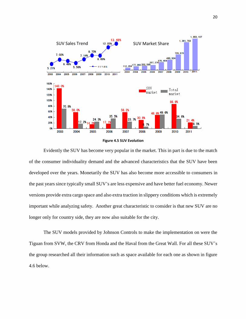
The SUV situation in the market was also researched to show the sponsor company the
current situation vs. last years. Figure 4.5 demonstrates how there has been an exponentially
growth in the SUV sales trend from 2009 to 2011. Showing the same behavior the SUV market
share has been increasing also shown in Figure 4.5. Based on the investigation the SUV market
has done very well in the past years, however it is necessary to check how the rest of the market
has been doing to make a comparison. Figure 4.5 below shows the contrast between the total car
market growth rate and the SUV market growth rate. These results confirm the speculations about
the SUV market having a success in the following years which reinforce the purpose of the project.
Page 26
20
Figure 4.5 SUV Evolution
Evidently the SUV has become very popular in the market. This in part is due to the match
of the consumer individuality demand and the advanced characteristics that the SUV have been
developed over the years. Monetarily the SUV has also become more accessible to consumers in
the past years since typically small SUV’s are less expensive and have better fuel economy. Newer
versions provide extra cargo space and also extra traction in slippery conditions which is extremely
important while analyzing safety. Another great characteristic to consider is that new SUV are no
longer only for country side, they are now also suitable for the city.
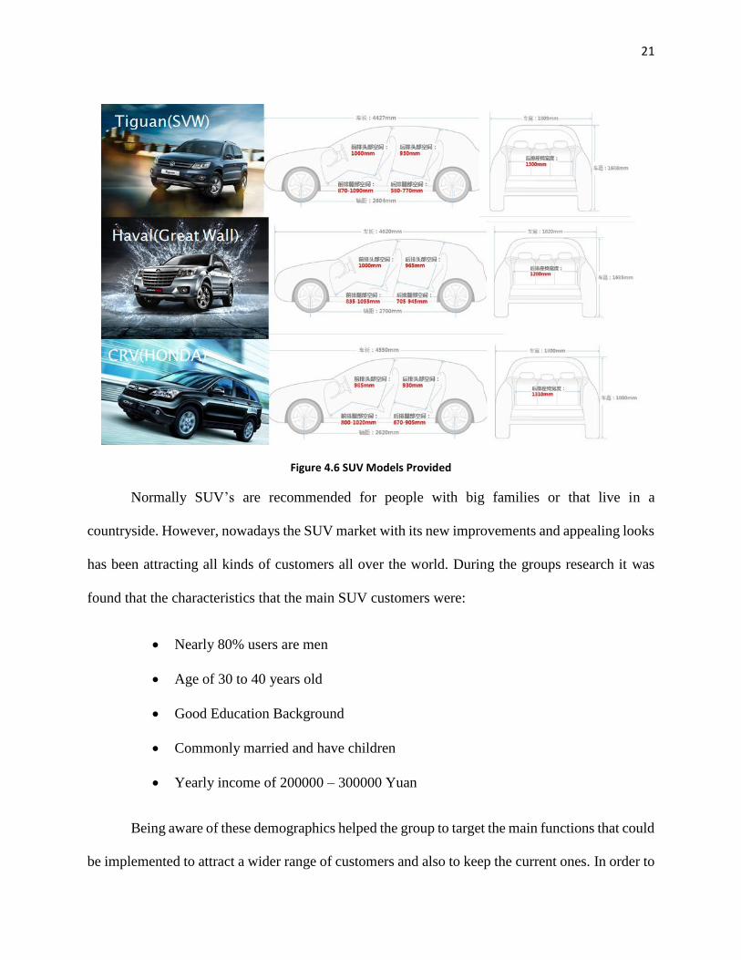
The SUV models provided by Johnson Controls to make the implementation on were the
Tiguan from SVW, the CRV from Honda and the Haval from the Great Wall. For all these SUV’s
the group researched all their information such as space available for each one as shown in figure
4.6 below.
SUV Sales Trend SUV Market Share
Page 27
21
Figure 4.6 SUV Models Provided
Normally SUV’s are recommended for people with big families or that live in a
countryside. However, nowadays the SUV market with its new improvements and appealing looks
has been attracting all kinds of customers all over the world. During the groups research it was
found that the characteristics that the main SUV customers were:
Nearly 80% users are men
Age of 30 to 40 years old
Good Education Background
Commonly married and have children
Yearly income of 200000 – 300000 Yuan
Being aware of these demographics helped the group to target the main functions that could
be implemented to attract a wider range of customers and also to keep the current ones. In order to
Page 28
22
do that, it was also necessary to relate the main features these customers based their decisions on,
while buying a SUV over any other car. These main features were found to be the following:
Off Road Capabilities
Simple Operation
Visuals
Extra passenger and cargo space
Multifunction
SUV drivers are known to take advantage of the cargo space. They usually use it to
transport heave and large equipment. Additionally, the driving capabilities during extreme climate
situations are very appealing features. Therefore the group focused in these main characteristics
for the final mechanism idea.
Page 29
23
Chapter 5. Results Throughout this project, we were able to learn a great deal of things. We not only got to
experience what the business culture was like, but we were also able to learn new technical skills.
Through the communication and mentoring from students, faculty and engineers we were able to
refine our skills in order to provide the results. We toned our CAD skills and expanded the CAD
software programs when taking our ideas to computer and using a different software than what we
had learned. One of the abilities that we were able to improve the most was the ability to work
with others and presenting our ideas. This was done through various meetings, networking and
presentations to professors and company employees.
5.1 Mechanism Ideas
Throughout the progress of the project we had to brainstorm constantly in the search for an
innovative idea. At first little instruction was provided with the purpose to help us think outside
the box, or rather different than someone in the field of car seat manufacturing. We were to show
our different ideas at our meetings with the company. There our ideas were reviewed and criticized
so that we could move to the next phase. Our next phase was to combine our ideas and concepts
with the ones that the company had worked on. Then, we would have another brainstorm for new
ideas based on the new set of concepts.
The focus was to come up to develop what desired path of the cushion and backrest would
be. At first we were just given the cushion and backrest model and from it we were to think of
possible paths for the cushion and backrest in order to achieve the folding operation. Shortly after
we were provided with all the requirements as to what our constraints were sample shown in
Appendix B. The reason to let us develop ideas without all the constraints was so that they could
see ideas that were outside the box and provide inspiration for something innovative.
Page 30
24
After presenting various ideas that were not limited by the common knowledge of the
engineers that had been on the field for several years and have a better understanding of what
works and what does not, they provided us with feedback. With this feedback we did iterations
and narrowed down our concepts and presented to the engineers. The engineers picked the
concepts path to be focused on which are shown in figure 5.1. The concepts were compared and
given scores based on company criteria for mechanism designs. Explanation of terms used in the
comparison can be found in Appendix C.
Figure 5.1 Design Concept Finalists
After the brainstorming and narrowing down options we then had to detail our options. We
started to develop concept ideas for the mechanisms of these concepts as seen in figure 5.2. After
the brainstorm we would again meet with the company and have the engineers give us their input
Page 31
25
on it. Then we would go back to the drawing board and iterate the ideas. Then again some were
discarded and the ideas narrowed.
Figure 5.2 Sample Brainstorm Mechanism Concept
Now with narrowed down concepts and mechanisms we could start to design in more detail
by starting to do model in CAD. By performing the models we would be able to do analysis of the
designs. After, having the three concepts we did models for each one. In each one we still were
still keeping options open for new ideas that may surge while working on the model.
5.2 Final Design
Figure 5.3 Box Concept Design
Page 32
26
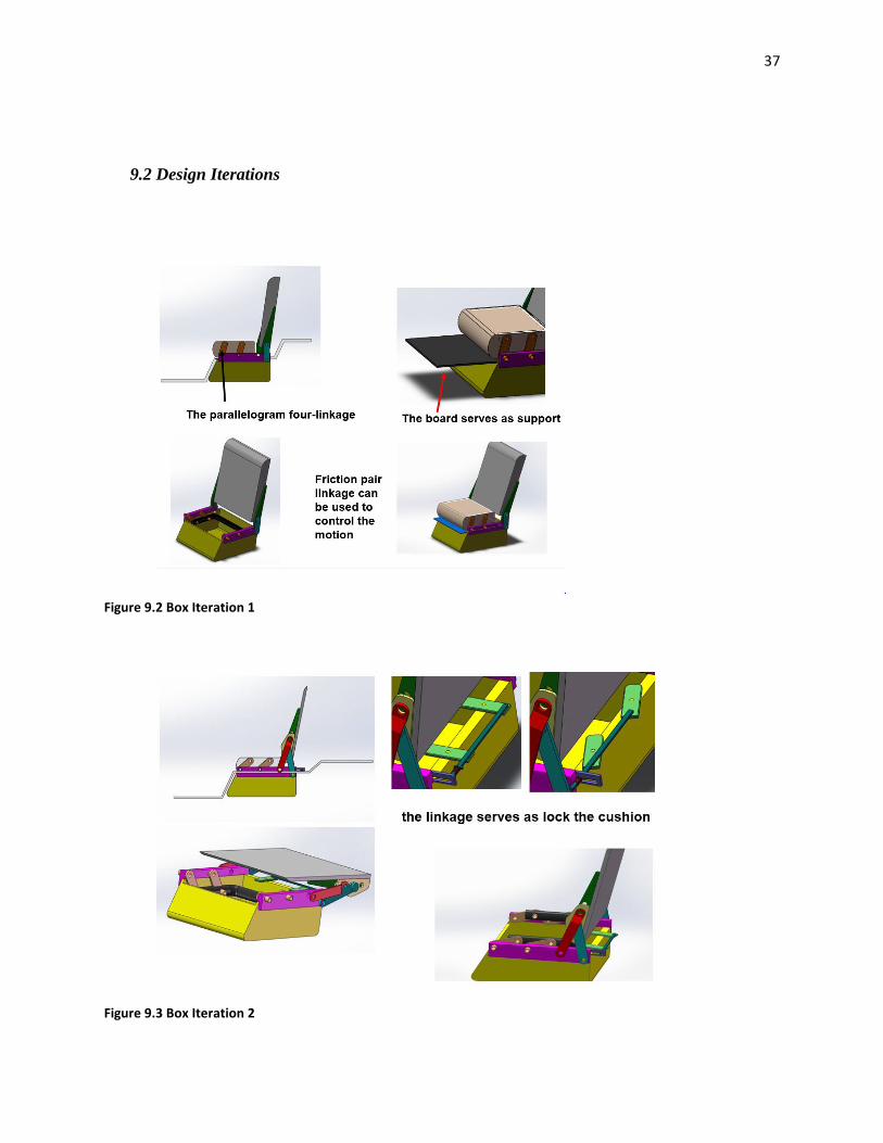
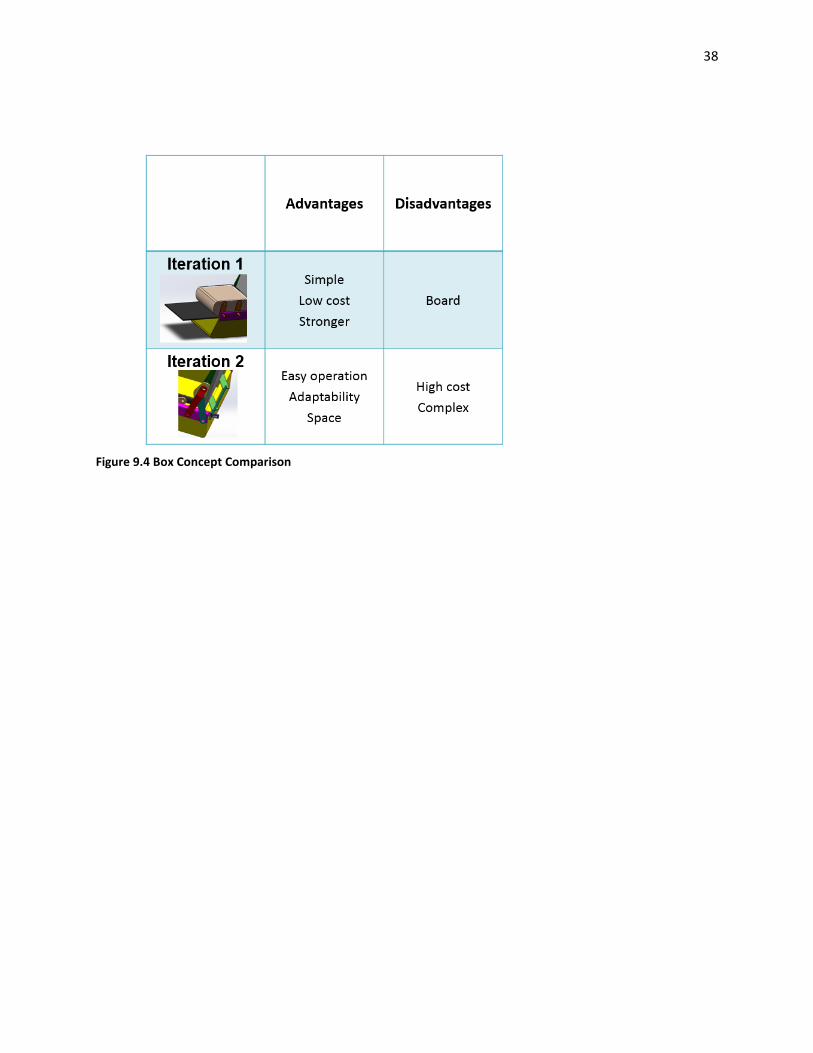
For the box concept shown in figure 5.3, we developed a few iterations as initially the idea
was not as feasible to the engineers as other options. The way this concept works is that the cushion
is supported by boards on a parallelogram four-linkage that locks it in place, and moves out of the
way for folding when operated. This concept has the advantage that the mechanism for it is not
very complex nor is it expensive in comparison. However, one disadvantage is the environment
adaptability, as this concept would require a bottom box for the cushion to be stored, and that may
not be of preference to the customer.
However, they we still continue to develop the box idea and models.
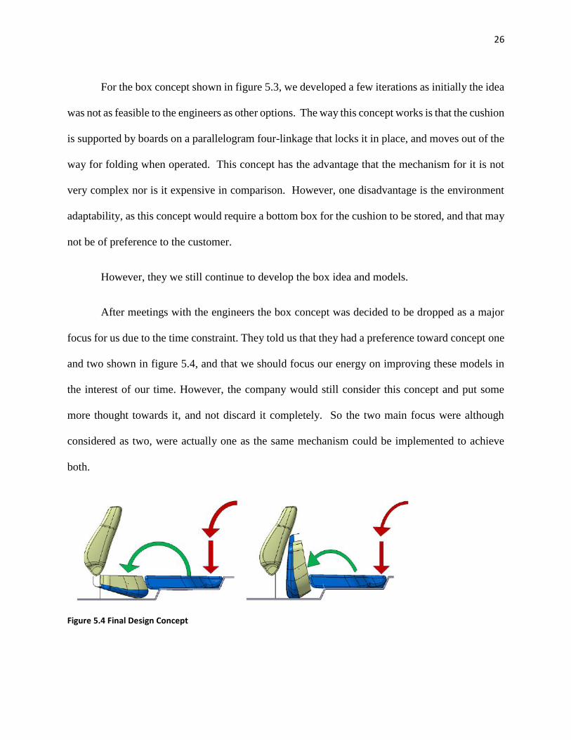
After meetings with the engineers the box concept was decided to be dropped as a major
focus for us due to the time constraint. They told us that they had a preference toward concept one
and two shown in figure 5.4, and that we should focus our energy on improving these models in
the interest of our time. However, the company would still consider this concept and put some
more thought towards it, and not discard it completely. So the two main focus were although
considered as two, were actually one as the same mechanism could be implemented to achieve
both.
Figure 5.4 Final Design Concept
Page 33
27
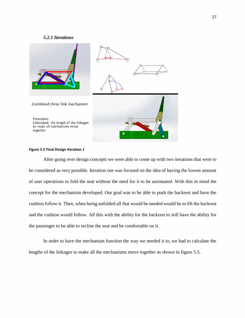
5.2.1 Iterations
Figure 5.5 Final Design Iteration 1
After going over design concepts we were able to come up with two iterations that were to
be considered as very possible. Iteration one was focused on the idea of having the lowest amount
of user operations to fold the seat without the need for it to be automated. With this in mind the
concept for the mechanism developed. Our goal was to be able to push the backrest and have the
cushion follow it. Then, when being unfolded all that would be needed would be to lift the backrest
and the cushion would follow. All this with the ability for the backrest to still have the ability for
the passenger to be able to recline the seat and be comfortable on it.
In order to have the mechanism function the way we needed it to, we had to calculate the
lengths of the linkages to make all the mechanisms move together as shown in figure 5.5.
Page 34
28
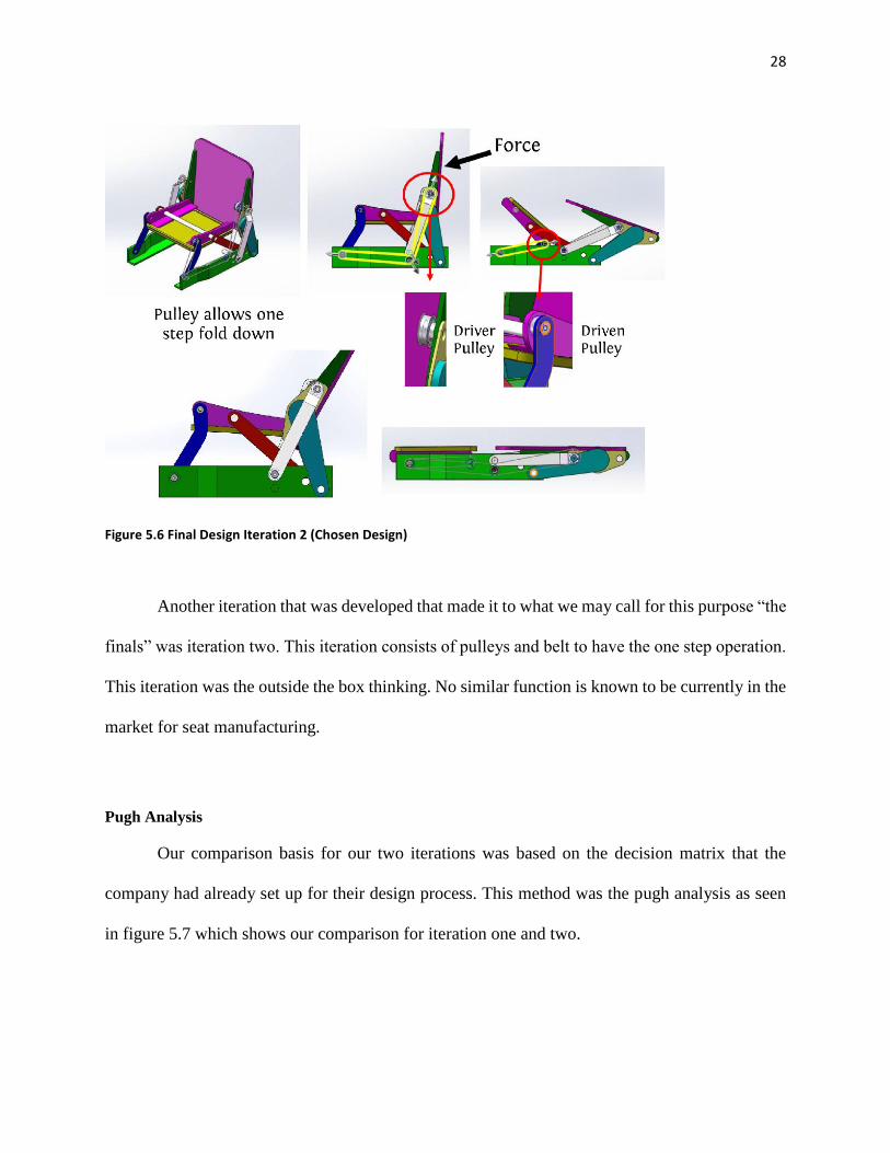
Figure 5.6 Final Design Iteration 2 (Chosen Design)
Another iteration that was developed that made it to what we may call for this purpose “the
finals” was iteration two. This iteration consists of pulleys and belt to have the one step operation.
This iteration was the outside the box thinking. No similar function is known to be currently in the
market for seat manufacturing.
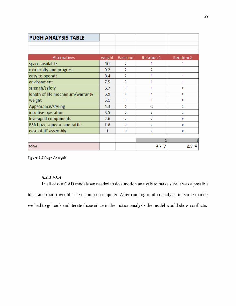
Pugh Analysis
Our comparison basis for our two iterations was based on the decision matrix that the
company had already set up for their design process. This method was the pugh analysis as seen
in figure 5.7 which shows our comparison for iteration one and two.
Page 35
29
Figure 5.7 Pugh Analysis
5.3.2 FEA
In all of our CAD models we needed to do a motion analysis to make sure it was a possible
idea, and that it would at least run on computer. After running motion analysis on some models
we had to go back and iterate those since in the motion analysis the model would show conflicts.
Page 36
30
Figure 5.8 Our ANSYS Tests
In order to better represent our design we had to do structures testing to provide the
company with a good pitch for this idea. The main concert with iteration two was that pulleys and
belt were not currently being used in the market, which would lead to the question of life and
reliability of the product.
For this we did research on similar designs and then compared our ANSYS results shown
in figure 5.8, for validation of our tests. We can see the sample test from the online study in figure
5.9.
Figure 5.9 ANSYS Results From Online Study
Page 37
31
The study from hpcgears was mainly an application for large production lines were they
were testing the pulleys and belts with different materials to see if they would be able to run with
a cheaper material.
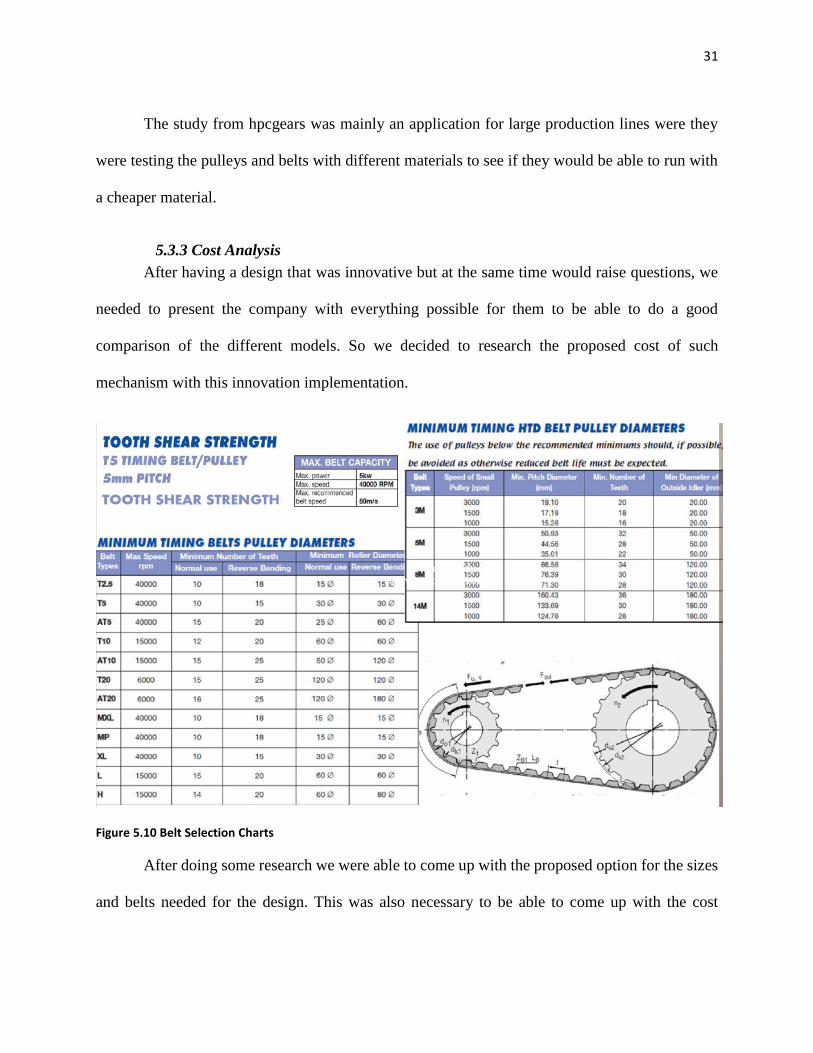
5.3.3 Cost Analysis
After having a design that was innovative but at the same time would raise questions, we
needed to present the company with everything possible for them to be able to do a good
comparison of the different models. So we decided to research the proposed cost of such
mechanism with this innovation implementation.
Figure 5.10 Belt Selection Charts
After doing some research we were able to come up with the proposed option for the sizes
and belts needed for the design. This was also necessary to be able to come up with the cost
Page 38
32
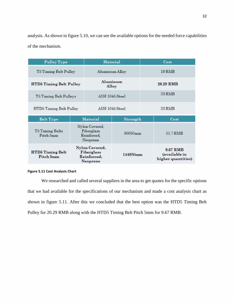
analysis. As shown in figure 5.10, we can see the available options for the needed force capabilities
of the mechanism.
Figure 5.11 Cost Analysis Chart
We researched and called several suppliers in the area to get quotes for the specific options
that we had available for the specifications of our mechanism and made a cost analysis chart as
shown in figure 5.11. After this we concluded that the best option was the HTD5 Timing Belt
Pulley for 20.29 RMB along with the HTD5 Timing Belt Pitch 5mm for 9.67 RMB.
Page 39
33
Chapter 6. Conclusion and Recommendations The main constrain while doing the project was the limited time provided. By the time the
group finally had a feasible idea it was necessary to learn the CAD software CATIA. All members
were not familiarized with the software and were not able to use any other because that was the
one utilized by the sponsor company. Johnson Controls was extremely supportive in the issue but
still was a struggle with the time frame provided.
Additionally, the language barrier resulted to be a great challenge. The group was
able to overcome this obstacle, however slowed down the productiveness during meetings and
presentations. Luckily the advisor provided by Johnson Controls spoke perfect English and the
communication was not an issue there.
The communication between the company and Johnson Controls turned out to be
very efficient. The team visited the company every week and sometimes twice a week and the
meetings lasted sometimes more than four hours. The advisors and engineers from the company
were extremely helpful and worked very closely with the team of students.
The group is very pleased with the project results and hopes Johnson Controls is as
satisfied. The group also hopes the company sponsors more WPI and SHU student projects in the
future. Johnson Controls is a great place to work for and we feel honored to have had the
opportunity to contribute in their everyday success.
Page 40
34
Chapter 7. References
"CATIA Tutorial." CATIA Tutorial. N.p., n.d. Web. 10 Nov. 2012.
"CRV China." N.p., n.d. Web. 09 Sept. 2012.
"Evolution of The SUV." AskMen. N.p., n.d. Web. 22 Sep. 2012.
"EXPLORE JOHNSON CONTROLS." Johnson Controls. N.p., n.d. Web. 10 Oct. 2012.
"Great Wall Motors." Great Wall Motors Haval. N.p., n.d. Web. 9 Oct. 2012.
"History of the SUV (Sport Utility Vehicle)." History of the SUV. N.p., n.d. Web. 13 Oct. 2012.
"Looks Little. Acts All Grown Up." Volkswagen Tiguan. N.p., n.d. Web. 9 Oct. 2012.
"Rear Seat Folding Mechanisms." Porter Group LLC. N.p., n.d. Web. 09 Oct. 2012.
Singathia, Deepak. HPC Gears. Working paper. YMCA University of Science and Technology,
5 Sept. 2012. Web. 10 Nov. 2012.
Zhong, Lu. Safety Rear Seat on China Rear Seat. IEEE. IEEE, 21 July 2012. Web. 09 Oct. 2012.
Page 41
35
Chapter 8. Appendix A
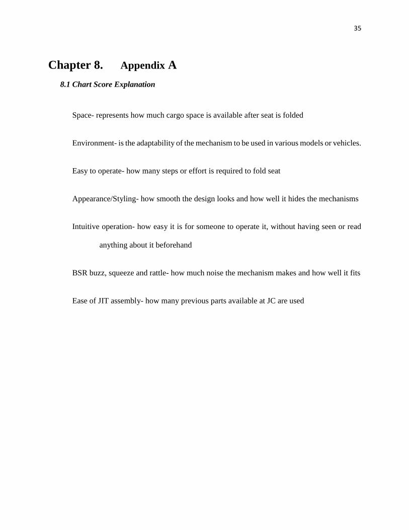
8.1 Chart Score Explanation
Space- represents how much cargo space is available after seat is folded
Environment- is the adaptability of the mechanism to be used in various models or vehicles.
Easy to operate- how many steps or effort is required to fold seat
Appearance/Styling- how smooth the design looks and how well it hides the mechanisms
Intuitive operation- how easy it is for someone to operate it, without having seen or read
anything about it beforehand
BSR buzz, squeeze and rattle- how much noise the mechanism makes and how well it fits
Ease of JIT assembly- how many previous parts available at JC are used
Page 42
36
Chapter 9. Appendix B
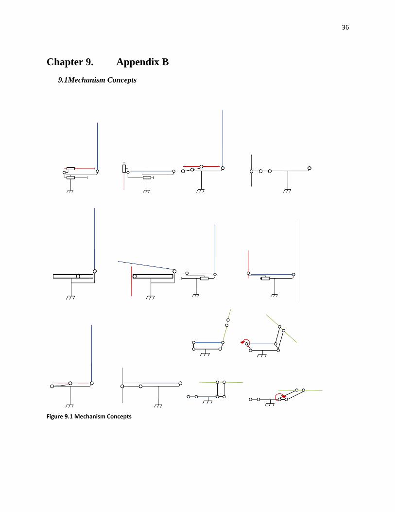
9.1Mechanism Concepts
Figure 9.1 Mechanism Concepts
Page 43
37
9.2 Design Iterations
Figure 9.2 Box Iteration 1
Figure 9.3 Box Iteration 2
Page 44
38
Figure 9.4 Box Concept Comparison
Page 45
39
Chapter 10. Appendix C
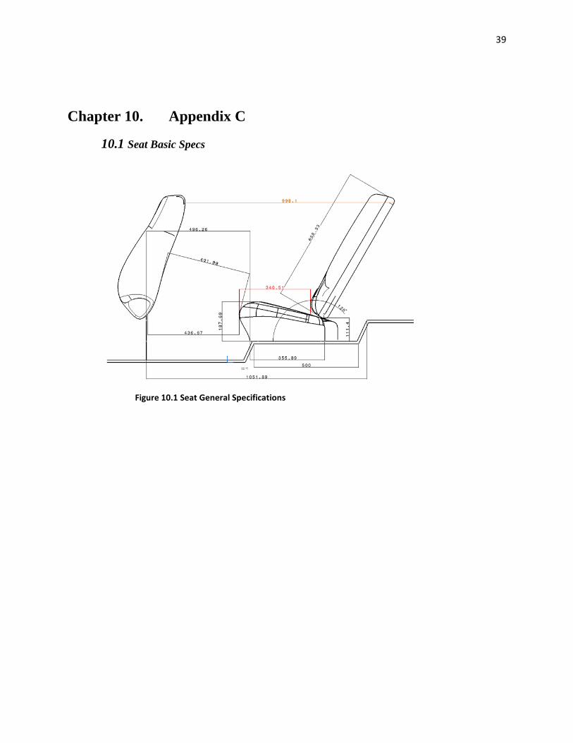
10.1 Seat Basic Specs
Figure 10.1 Seat General Specifications
Page 46
40
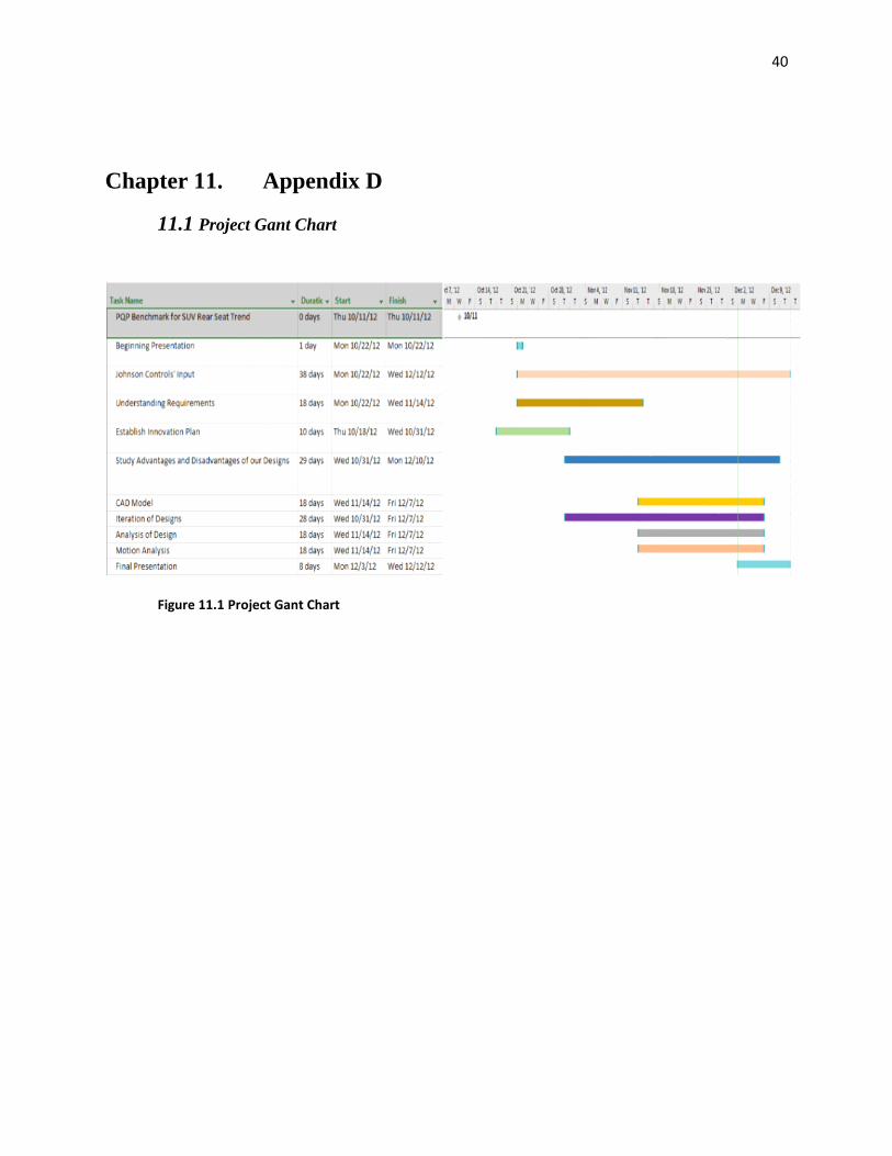
Chapter 11. Appendix D
11.1 Project Gant Chart
Figure 11.1 Project Gant Chart